1
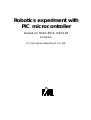
Robotics experiment with PIC microcontroller l 1
Robotics experiment with
PIC microcontroller
based-on Robo-PICA robot kit
3rd Edition
(C) Innovative Experiment Co.,Ltd.
INNOVATIVE EXPERIMENT
2 l Robotics experiment with PIC microcontroller
Contents
Chapter 1 Part list of Robo-PICA and Introduce software tools...............5
1.1 Robo-PICA part list
1.2 Hand tools for making robot kit
1.3 Software development tools for Robot programming
Chapter 2 RBX-877V2.0 Robot Controller board...................................25
2.1 Technical features
2.2 Circuit description
Activity 1 : Write programs for testing RBX-877 V2.0 Controller board
Chapter 3 Building Robo-PICA kit..............................................................35
Activity 2 : Make the Robo-PICA
Chapter 4 Simple robot ’s programming control...................................45
Activity 3 : Simple movement control
Activity 4 : Speed control of Robo-PICA
Chapter 5 Contactless object detection...............................................57
5.1 PIC16F8875s A/D converter
5.2 ADC register
5.3 ADC configuration
5.4 A/D Conversion procedure
5.5 GP2D120 : 4 to 30cm. Infrared distance sensor
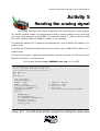
Activity 5 : Reading the Analog signal
Activity 6 : Testing GP2D120
Activity 7 : Contactless object detection robot
Robotics experiment with PIC microcontroller l 3
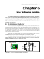
Chapter 6 Line following mission..............................................................71
6.1 Infrared reflector sensor
Activity 8 : Reading the Line tracking sensor
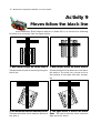
Activity 9 : Moves follow the black line
Chapter 7 Remote control experiment...................................................79
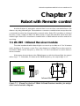
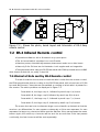
7.1 38kHz Infrared receiver module
7.2 Infrared remote control 4 channels
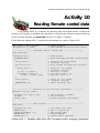
Activity 10 : Reading Remote control data
Activity 11 : IR control Robo-PICA’s movement
Appendix A : Activating the License Key
of mikroC compiler................................................................87
E
mikroC is registered trademark of mikroElektronika (www.mikroe.com).
PIC and PICkit2 TM are registered trademarks of Microchip Technology
(www.microchip.com).
4 l Robotics experiment with PIC microcontroller
Robotics experiment with PIC microcontroller l 5
Chapter 1
Part list of Robo-PICA and
Introduce software tool
1.1 Robo-PICA part list
There are 2 groups :
1.1.1 Mechanical parts
1.1.2 Electronic parts
1.1.1 Mechanical parts
Motor Gearbox – Uses
a 4.5V (9V max.) and
180 mA DC motor with
a ratio of 48:1; torque
4kg/cm; comes with
the mounting.
Track wheel set - includes 3lengths of Track wheel, many
support
wheels
and
sprockets, axels and shaft
bases
The Plate set and 4-types
of the color-mixed Plastic
Joiner (10 of Straight
Joiner, 10 of Right-angle
Joiner, 10 of Obtuse
Joiner and 3/5/12 Holes
straight joiners)
Many sizes of Screw and
Nut
(Screw : 3x6mm.,3x10mm.,
3x15mm.,3x25mm. and
3x35mm., 3mm. nuts), Flat
head screws and Thumb
screws.
Set of Plastic Spacers
(length : 3mm., 15mm.
and 25 mm.)
Hex Standoffs : 3x30mm.
6 l Robotics experiment with PIC microcontroller
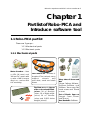
1.1.2 Electronic parts
ZX-01
Switch input
(x2)
GP2D120
4 to 30cm. Infrared
Distance sensor
RBX-877V2.0 PIC16F887 Robot Experiment Board
ZX-IRM
38kHz Infrared Receiver
ER-4
Infrared
Remote Control
ZX-03
Infrared Reflector
(x2)
ZX-POTH
Potentiometer (x1)
USB cable
USB Programmer board
with ICD2 cable
4 of AA batteries
(Rechargable battery is
recommended
- not include this kit)
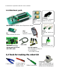
1.2 Tools for making the robot kit
Cutter plier
A sharp-tipped
hobby knife or
Handy Cutter
Philips Screwdriver
Computer
Install Windows98SE or
higher and has both RS-232
serial port and Parallel port
Robotics experiment with PIC microcontrollerl 7
1.3 Software development tools for Robot programming
The RoboPICA kit uses the PIC Micrcontroller PIC16F887. Builders can write the
controlled program in assembly, BASIC and C language. Only BASIC and C program
language requires the use of a compiler software.
However in this kit all examples are in C language with mikroC compiler from
mikroElektronika (mikroE : www.mikroe.com). The Robo-PICA robot kit can use this compiler as well.
The demo version of Mikro C compiler is used for this robot kit. Builders who need
to develop the advance program will need to purchase the full version from MikroE at
their webiste. The demo version of mikroC can be downloaded from http://
www.mikroe.com. However in the Robo-PICA robot kit, this software is in the bundled
CD-ROM. You must download the mikroC manual latest version from mikroElektronika
website. This building manual does not describe all the instructions.
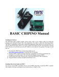
Another one tools is PIC microcontroller programmer software. The Robo-PICA
provides a USB programmer. Its function is compatible Microchip’s PICkit2TM programmer. The software can use PICkit2TM programming software. Free downlaod the latest
version at www.microchip.com.
1.3.1 mikroC Compiler (Demo version)
1.3.1.1 Overview
mikroC is a powerful, feature rich development tool for PICmicros. It is designed
to provide the customer with the easiest possible solution for developing applications
for embedded systems, without compromising performance or control.
mikroC provides a successful match featuring highly advanced IDE, ANSI compliant compiler, broad set of hardware libraries, comprehensive documentation, and
plenty of ready-to-run examples.
mikroC allows you to quickly develop and deploy complex applications:
l Write your C source code using the highly advanced Code Editor
l Use the included mikroC libraries to dramatically speed up the development:
data acquisition, memory, displays, conversions, communications…
Special thanks : All information about mikroC Compiler and PICkit2 Programming software are
referenced from owner website and documentation (www.mikroe.com and www.microchip.com).
Thanks for all free and open-source developement tools. User who need the full features of mikroC
compiler can purchase on-line at www.mikroe.com.
8 l Robotics experiment with PIC microcontroller
l Monitor your program structure, variables, and functions in the Code
Explorer. Generate commented, human-readable assembly, and standard HEX compatible with all programmers.
l Inspect program flow and debug executable logic with the integrated
Debugger. Get detailed reports and graphs on code statistics, assembly listing, calling
tree…
l mikroE have provided plenty of examples for you to expand, develop,
and use as building bricks in your projects.
l In Demo version, hex output is limited to 2k of program words.
1.3.1.2 Installation the mikroC compiler Demo version
Download the latest version from mikroElektronika website; www.mikroe.com.
Run the installation file. Addition, you must download the 5 of necessary documentation
files about compiler manual, Creating First Project in mikroC for PIC, Quick Reference
Guide for C language, Compilers IDE document and Obtaining and Activating the License Key.
You can see all C syntax and all function details from the mikroC manual. In this
manual would be describe about the robot activities only.
1.3.2 PICkit2TM Programming Software
The PICkit™ 2 Microcontroller Programming software is capable of programming
most of Microchip’s Flash microcontrollers. For specific products supported, see the
README file or check with Microchip’s website.
The full featured Windows programming interface supports baseline (PIC10F,
PIC12F5xx, PIC16F5xx), midrange (PIC12F6xx, PIC16F), PIC18F, PIC24, dsPIC30, and dsPIC33
families of 8-bit and 16-bit microcontrollers, and many Microchip Serial EEPROM products.
The PICkit™ 2 Microcontroller Programming software works with a PICkit2TM OEM
USB programmer. The USB programmer is the in-system programming via ICD2 jack.
1.3.2.1 PICkit2TM Programming Software installation
1.3.2.1.1 Install from PX-200 CD-ROM
The working software of the USB programmer is PICkit2TM Programming Software.
The newer version is developed from Microsoft.NET. Thus, user must install the
Microsoft.NET Framework first.
Robotics experiment with PIC microcontrollerl 9
(A) Install of the Microsoft .NET Framework
First thing to do is to install the Microsoft.NET Framework. Select from the
folder PICkit 2 Setup v2.01 dotNET à dotnetfx in the bundled CD-ROM. Double-click at
dotnetfx.exe file. After complete, install the PICkit2TM Programming Software by doubleclick at PICkit2Setup.msi file. The software installation will start.
(B) Microsoft .NET Framework is installed ready
User can install the PICkit2TM Programming Software by enter to folder PICkit
2 Setup v2.01x in the bundled CD-ROM of Robo-PICA kit. Double-click at PICkit2Setup.msi
file. The software installation will start.
1.3.2.1.2 Install from the internet.
Visit the Microchip website at www.microchip.com. Select Development tools
webpage and enter to PICkit 2 Programmer/Debugger webpage.
(A) Install of the Microsoft .NET Framework
For user who have not install Microsoft .NET Framework, they will need to
install it first via downloading the file from topic PICkit2V2.01 Install with .NET Framework. You will get the PICkit 2 Setup v2.01 dotNET.zip file (version number may vary).
Extract this file and store it in the folder PICkit 2 Setup v2.01 dotNET. Enter to this folder
and into the dotnetfx folder. Double-click at dotnetfx.exe file to start Microsoft .NET
Framework installation. After this is completed, install the Pickit2TM Programming Software by double-clicking on the PICkit2Setup.msi file. THe software installation will start.
(B) Microsoft .NET Framework is installed ready
Users who have Microsoft .NET Framework already installed can download the setup file from PICkit2V2.01 Install header. You will get file PICkit 2 Setup v2.01.zip
(version number may be vary) Extract this file and store in the folder PICkit 2 Setup v2.01.
Enter to this folder and double-click on the PICkit2Setup.msi file to start the software
installation.
After run the installation setup file ; PICkit2Setup.msi. Click on the accept button
on each step and follow the installation progress until it is finished.
10 l Robotics experiment with PIC microcontroller
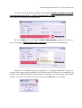
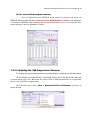
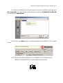
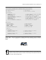
1.3.2.2 Using PICkit2TM Programming Software
1.3.2.2.1 Testing hardware connection
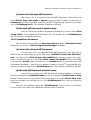
(1) Connect the USB cable between the programmer and Computer’s USB port.
Open the software Pickit2TM Programming Software by entering the Start à All programs
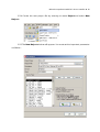
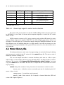
à Microchip à Pickit 2 V201. The main window will appear as shown in figure 1-1.
(2) On successful connnection, the message PICkit 2 found and connected will
appear in the Status box.
Command menu
Status box
Progress bar
Short cut
button
Figure 1-1 : The screen of Pickiit2TM Programming Software
Inform the
destination
of HEX file
Robotics experiment with PIC microcontrollerl 11
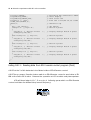
(3) If the connection is incompleted. The message PICkit 2 not found. Check USB
connections and use Tools à Check Communication to retry will appear in the Status
box. Check the cables and connections.
(4) Go to Tools menu and select Check Communication command. If all’s correct, the message PICkit 2 found and connected will be show in the Status box.
However if everytime during re-connection or checking hardware, it does not
connect the target microcontroller at ICD2 jack and ICSP point or any mismatch in
number, the warning dialog box will appear. It will warn you about any error supply
voltage. You need not worry about this, click on the OK button to continue.
12 l Robotics experiment with PIC microcontroller
1.3.2.2.2 Command menu description
FILE
• Import File – Import a hex file for programming
• Export File – Export a hex file read from a device
• Exit – Exit the program (duplicated with the Quit button)
DEVICE FAMILY
• Baseline (12-bit Core) – Configures the programming software for baseline Flash
devices
• Mid-range - Configures the programming software for 14-bit core flash devices. The devices in this range include PIC12F6xx and 16F6xx, 7x, 7xx, 8x, 8xx. When
selected, software will check the connection target at ICD2 and ICSP terminal. If found
the correct device, device number will appear at Device line in Midrange Configuration box. Click the OK button to continue. For RBX-877V2.00 board would be use this
group chip because the controller board provides PIC16F887; it is mid-range PIC
microcontroller.
• PIC18F - Configures the programming software for PIC18F core flash devices.
• PIC18F_J_ - Configures the programming software for PIC18FxxJxx low voltage
devices.
• PIC24 - Configures the programming software for 16-bit core devices; PIC24FJxx.
• dsPIC30 - Configures the programming software for 16-bit core devices; dsPIC30Fxx.
• dsPIC33 - Configures the programming software for 16-bit core devices;
dsPIC33Fxx.
Robotics experiment with PIC microcontrollerl 13
PROGRAMMER
• Read Device – Reads the program memory, data EEPROM memory, ID locations, and Configuration bits.
• Write Device – Writes the program memory, data EEPROM memory, ID locations, and Configuration bits.
• Verify – Verifies the program memory, data EEPROM memory, ID locations and Configuration bits read from the target MCU against the code stored in the programming software.
• Erase – Performs a bulk erase of the target MCU. OSCCAL and band gap values are preserved (PIC12F629/675 and PIC16F630/676 only).
• Blank Check – Performs a blank check of program memory, data EEPROM
memory, ID locations and Configuration bits.
• Verify on Write - Verifies program memory, data EEPROM memory, ID locations
and Configuration bits read from the target MCU against the code stored in the programming software with word per word.
• Full Erase (OSCCAL and BG erased) – Performs a bulk erase including the OSCCAL
and Band Gap (BG) values (PIC12F629/675 and PIC16F630/676 only).
• Regenerate OSCCAL – Regenerates the OSCCAL value (only for PIC12F629/
675 and PIC16F630/676). The AUX line must be connected to the RA4/T1G pin.
• Set Band Gap Calibration Value – Sets the band gap value.
• Write on PICkit Button - Set for supporting of programming the target microcontroller witth PROGRAM switch on the USB programmer board.
TOOLS
• Enable Code Protect – Enables code protection for Flash program memory.
• Enable Data Protect – Enables code protection for EEPROM data memory.
• Set OSCCAL - Sets the OSCCAL value for alignment internal clock frequency.
• Target VDD Source – Power target from the USB Programmer.
Auto-Detect : Select to USB programmer turn on or off the supply voltage
to target microcontroller automatically (not suggess to use this option).
Forced PICkit2 : Set the programmer to supply the suitable voltage to target microcontroller. After select, LED at Targer position will light and at VDD PICkit2 box
on screen will check atr On position. User can adjust the supply voltage from selection
box in the right-hand (not suggess to use this option).
Forced Target : Select to inform the software knows about the target has
voltage applied. Suggess to use this option for safty operation. Also in this option, user
must apply the supply voltage to the target PIC microcontroller.
14 l Robotics experiment with PIC microcontroller
• Fast Programming - Select the PX-200 to programs the Flash device with high speed.
• Check Communication – Verifies communication with the USB Programmer
and reads the device ID of the target MCU.
• Download PICkit 2 Firmware – Performs a download of the USB Programmer
firmware operating system. (this USB programmer is compatible PICkit2TM Programmer).
Sometime call this function to OS update.
Help
Displays all user manual, technical document and a dialog box indicating the
version and date.
1.3.2.2.3 Important things to know in using the PICkit2TM Programming Software
Editing memory value
The PICkit2TM Programming Software supports the editing memory value in each
address, both Flash program and data EEPROM memory. User can click at any address
that need to change the value and input the new value directly.
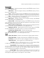
Moreover user can select to access both memory types and only one.
(a) Access only EEPROM data memory
Click at Enabled box in Program Memory border to remove the mark. At
EEPROM data border, it will show Write and Read EEPROM data only in red message. It
means user can read and write only EEPROM data memory. See the illlustration below.
-
Robotics experiment with PIC microcontrollerl 15
(b) Access only Flash program memory
Click at Enabled box in EEPROM data border to remove the mark. At
EEPROM data border will show Preserve device EEPROM data on write in red message.
It means the EEPROM data memory will be protected. User can access only Flash program memory. See the illlustration below.
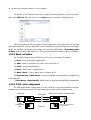
1.3.2.3 Updating the USB Programmer Firmware
To update the programmer firmware Operating System, complete the following steps.
(1) Download the latest PICkit 2 Operating System from the Microchip web site
at www.microchip.com. Because the Robo-PICA’s USB programmer is compatible
Microchip’s PICkit2TM programmer.
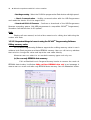
(2) From the menu, select Tools à Download PICKit 2 OS Firmware, as shown in
figure below
16 l Robotics experiment with PIC microcontroller
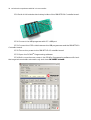
(3) Browse to the directory where the latest Operating System code was saved,
Select the PK2*.hex file and click on the Open button as shown in figure below.
(4) The progress of the OS update will be displayed in the status bar of the programming software and the Busy LED on the USB Microcontroller Programmer will flash.
When the update completes successfully, the status bar will display “Operating System
Verified” and the Busy LED will go out. The operating system update is then complete.
1.3.2.4 Short cut button
The PICkit2TM Programming Software has 7 short cut buttons as follows :
(1) Read : Read data from target MCU.
(2) Write : Write or program the code into target MCU.
(3) Verify : Verify programming.
(4) Erase : Erase data in target MCU.
(5) Blank Check : Check blank data in target MCU.
(6) Import Hex File + Write Device : Open the HEX file and program into target MCU
automatically
(7) Read Device + Export Hex File : Read device and save as the HEX file automatically.
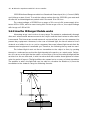
1.3.2.5 ICD2 cable assignment
The USB Programmer comes with an ICD2 cable for connecting between the programmer and the target board. The wire assignment of this cable is shown below.
ICD2 jack
~
~
PGC
PGM
PGD
$
GND
Vpp
USB
Programmer
side
RBX-877 V2.0 Robot Controller board
Vdd
~
~
PGM
PGD
Vdd
ICD2 cable
PGM
PGC
PGD
GND
Vdd
Vpp
Top view
PGM
PGC
PGD
GND
Vdd
Vpp
PGC
GND
Vpp
ICD2 jack pin assignment
on target board
Robotics experiment with PIC microcontrollerl 17
1.4 Programming devleopment for Robo-PICA
The summary of steps of program the Robo-PICA robot kit are as follows :
1. Create the C project file with mikroC IDE software.
2. Compile the project file.
3. If any error occurs, edit the C program to fix the error and compile the
project file until all are correct.
4. The HEX file would be created after the compilation is completed.
5. Open the PICkit2TM Programming software. Connect the USB programmer
with USB port and connect the ICD2 cable between the USB Programmer and the RBX877 V2.0 Controller board at ICD2 jack.
6. Download the HEX file to the RBX-877 V2.0 Controller board of RobotPICA.
7. Run the program and check the hardware operation. If it is not correct,
go back to edit the C program, compile and download again. Do these steps unitl the
operation are completed.
1.5 Getting Start
From here, we will describe about the getting start of programming development
for the Robo-PICA. This robot kit is controlled by the RBX-877 V2.0 Robot Controller board.
The heart of this controller board is PIC16F887 chip. The programming development includes 2 main steps as C programming development and Download the HEX file to
microcontroller.
The C programming development will be using mikroC IDE included C compiler
and the other provides support tools and libraries. However this kit will work with the demo
version. You can purchase the full version for more programming at www.mikroe.com.
You can develop the C project file and test the operation of the Robo-PICA’s hardware from these procedures below.
1.5.1 Install the mikroC software tools following the instruction manual. See this document in Robo-PICA’s CD-ROM or download the update document from www.mikroe.com.
1.5.2 Install the PICkit2 Programming software for USB programmer.
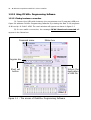
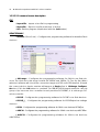
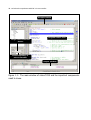
1.5.3 Open the mikroC IDE by clicking at Start à Programs à Mikroelktronika à
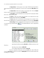
mikroC à mikroC. The main window will appear. The Figure 1-1 shows the main window of
mikroC IDE and the important components.
18 l Robotics experiment with PIC microcontroller
Complie button
Program editor area
Target microcontroller
device
Clock frequency of
microcontroller
Output window
Figure 1-1 : The main window of mikroC IDE and the important components
need to know.
Robotics experiment with PIC microcontrollerl 19
1.5.4 Create the new project file by entering to menu Project and select New
Project...
1.5.5 The New Project window will appear. You must set the important parameter
as follows :
20 l Robotics experiment with PIC microcontroller
(a) Project Name : Put the project name. mikroC IDE will create the folder to
support your project file which includes the C sourcecode. For example is Blink_LED project
file.
(b) Project Path : Select the location of your project file. Click the Browse
button to select the location. For example is D:\ROBO-PICA
(c) Description : Put the information of your porject file. For example is “Robo
PICA Code Blinking LED on RB3”
(d) Device : Select the target microcontroller. For the Robo-PICA kit and
RBX-877V2.0 Controller board must select to PIC16F887
(e) Clock : Select the clock frequency for the target microcontroller. For the
Robo-PICA kit and RBX-877V2.0 Controller board use 20MHz clock. Put the value 020.000000.
(f) Device Flags : Set the configuration for the target microcontroller. Developer
can set very easy by Default button
. The Default will set the 3 main configurations
as follows :
High Speed Oscillator enabled (HS_OSC) for 10MHz and above clock
frequency.
Watchdog timer disabled (WDT_OFF)
Low Voltage Programming disabled (LVP_OFF)
After the configuration is being set, click on the OK button. mikroC IDE would
close the New Project window and create the Blink_LED.C file with the blank editor area
for writing the C program.
Robotics experiment with PIC microcontrollerl 21
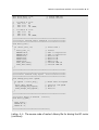
1.5.6 Type the C program following the Listing 1-1.
void main()
{
TRISB.F3=0;
while(1)
{
PORTB.F3=0;
Delay_ms(500);
PORTB.F3=1;
Delay_ms(500);
}
}
// Set RB3 as Output
// Infinite Loop
// LED_ON
// LED_OFF
Listing 1-1 : Blinking LED test code
1.5.7 Click on the Build Project button or Ctrl+F9 for compiling the project file.
1.5.8 Observe the error message at the Output window. If all is correct, it would
show the size of usage program memory of this file and Success message.
After that, you will get the HEX file; Blink_LED.HEX for downloading to the
Robo-PICA’s controller board; RBX-877V2.0.
22 l Robotics experiment with PIC microcontroller
1.5.9 Put 4 of AA batteries into battery holder of the RBX-877V2.0 Controller board.
1.5.10 Connect the USB programer with PC’s USB port
1.5.11 Connect the ICD2 cable between the USB programmer and the RBX-877V2.0
Controller board.
1.5.12 Turn-on the power to the RBX-877 V2.0 Controlller board.
1.5.13 Open the PICkit2TM Programming software.
1.5.14 If all connections are correct, the PICkit2TM Programming software will check
the target microontroller automaticcaly and show PIC16F887 is found.
Robotics experiment with PIC microcontrollerl 23
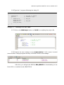
1.5.15 Select the HEX fle which require program to microcontroller by entering menu
File à Import Hex. The open HEX file window will appear. Select to D:\ROBO-PICA\Blink_LED
for selecting the Blink_LED.hex
1.5.16 Click on the Write button to download HEX file to the RBX-877 V2.0 Controlller
board.
1.5.17 Observe the result at RB3 LED on the RBX-877 V2.0 Controlller board.
RB3 LED of the RBX-877V2.0 Controller board blinks always.
INNOVATIVE EXPERIMENT
24 l Robotics experiment with PIC microcontroller
Robotics experiment with PIC microcontrollerl 25
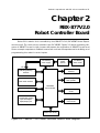
Chapter 2
RBX-877V2.0
Robot Controller Board
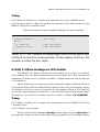
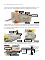
Robo-PICA robotic kit is controlled by the RBX-877 V2.0 (PIC16F887 Robot Experiment board). The main microcontroller is the PIC16F887. Figure 2-1 shows operating diagram of RBX-877 board. In this chapter will present the operation of RBX-877 board and
some example experiment. Builders must read and test all experiments for building and
programming the robot in next chapter.
+5V Switching
power supply
+5V
Low Battery
status circuit
+5V
LCD module
interface
ICD2 Programming
interface
Driving
Piezo speaker
UART Serial interface
I C bus interface
Battery
supply
(AA x4)
PIC16F887
microcontroller
Programmable Analog
input and Digital
Input/Output port
Driving DC motor
circuit
Driving RC servo
motor circuit
20MHz clock circuit
Figure 2-1 : RBX-877 V2.0 Robot controller boards block diagram
26 l Robotics experiment with PIC microcontroller
Piezo speaker
UART connector
(RC6 and RC7)
(RC0 )
LCD connector
I2C connector
(RD2, RD3, RD4-RD7)
(RC3 and RC4)
ICD2 in-system programming jack
Battery terminal
POWER
LOW BAT.
switch
indicator
PIC16F887 microcontroller
Servo motor output
(RC5, RB4 and RB5)
Interrupt port
Interrupt switch
(RB0/INT)
Programmable I/O port
(RA0-RA3, RA5, RE0-RE2)
LED monitor
(RB3)
DC motor output
(connect RC2, RD0, RD1
RA4 switch
and RC1, RD2, RD3)
Figure 2-2 : RBX-877 V2.0 Robot controller board layout
2.1 Technical features
l Controlled by PIC16F887 Microcontroller with 8Kword memory. Run with 20MHz clock
l Download the program via ICD2 jack.
l LCD16x2 display with LED back light and jumper to on/off control
l Piezo speaker
l a LED monitor
l Drive 2-DC motors 4.5V to 6V and 3-RC Servo motors (in range 4.8 to 6V)
l 9-Programmable ports support all analog inout and digtial input/output
l I2C bus port
l UART port for interfacing the serial device such as RS-232 transceiver, XBee
module and Bluetooth.
l Supply voltage from 4 of AA batteries (Rechargable battery is recommended)
l 2.375 x 6.25 Inches size
Robotics experiment with PIC microcontrollerl 27
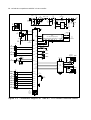
2.2 RBX-877 V2.0 board circuit description
2.2.1 Microcontroller circuit
The heart of this board is the PIC16F887 microcontroller. The 20MHz ceramic resonator, CR1 is used to make the 20MHz clock for PIC16F887.
2.2.2 Power supply
The RBX-877 V2.0 board contains a step-up switching power supply to supply +5V
regulated for PIC16F887. Although the level of battery will decrease when driving the
motor. This switching power supply circuit will maintain the +5V for microcontroller until
battery voltage level down to 1.5V
S1 is on-off switch to supply the voltage from batteries to RBX-877 V2.0 board. R3,
D1 and ZD1 ard used to limit the input voltage to IC2 not over 5.1V
IC1 is a switching power supply IC, NCP1450-5.0. It can support input voltage 1.5
to 4.2V range for regulating +5V supply voltage. ZD2 is used to limit output voltage of
NCP1450-5.0 not over +5V.
2.2.3 In-System Programming circuit
The RBx-877 V2.0 board require In-system programming via ICD2 or ISP connector. The USB programmer which is bundled in the Robo-PICA kit will connect to ICD2
jack of the RBX-877 V2.0 controller board. It use the supply voltage from USB port of
computer.
The programming signal will send to RB6 and RB7 pin of PIC16F887. The high voltage programming is sent to MCLR pin. All programming status would be show on the
PICkit2 Programming software on computer’s monitor. After programming complete,
this controller can work suddenly.
2.2.4 Display circuit
Character display :
The RBX-877 V2.0 board provides LCD module connector. It
supports 16 characters 2 lines LCD. PIC16F877’s RD4 to RD7 pin are assigned to D4 to D7
data pins, RD3 to E pin and RD2 to RS pin for selection data mode. VR1 is used to contrast
adjustment of LCD screen. In case using Back-light LCD, it provides a jumper to control
the LED back-light of LCD.
LED monitor : RBX-877 V2.0 board has a general purpose LED. They are connected to RB3 of PIC16F887 microcontroller via a current limited resistor.
Sound output : RBX-877 V2.0 board has a sound driver circuit. Connect RC0 pin to
a piezo speaker via a capacitor 10µF. This circuit can drive audio frequency signal.
However the piezo speaker has the resonance frequency of range 1kHz to 3kHz.
28 l Robotics experiment with PIC microcontroller
S1
POWER
+Vm
-
1
+V
C2
0.1/50V
K1
DC input
GND
2
L1
10µH
D2
MBRA340T3
+5V
C3
100µF
10V
IC1
KIA7042
ZD1
5.1V
Q1
FDS6680A
5
4
+5V
+5V
Vpp
11
PGD
40
39
PGC
J1
ICD2
32
CE
RD3
1
MCLR
IC3
PIC16F887
RD5
23
K3
SDA/RC4
18
K4
SCL/RC3
RD7
RD6
+5V
RD4
RB3
K6
RxD/RC7
26
RC6/TxD
RB5
R7
4k7
+5V
R9
150
K7
INT/RB0
+5V
6
33
4
22
6
E
Vo
D7 D6 D5 D4 D3 D2 D1 D0 R/W
14 13 12 11 10
9
8
7
5
30
RB2
RC1/CCP2
+5V
K15
AN5/RE0
8
K14
AN4/RA5
7
K9
AN3/RA3
5
K13
AN2/RA2
4
K12
AN1/RA1
3
K11
AN0/RA0
2
CR1
Ceramic
Resonator
20MHz
1
VR1
10k
3
BRIGHTNESS
28
27
36
LED3
RB3
R10
510
37
+Vm
K8
SERVO1
+Vm
K9
SERVO2
+Vm
K10
SERVO3
38
24
K18A-K18B
MOTOR-A
C8
0.1µF 50V
+5V +Vm
8
16
RB1
9
BACK LIGHT
ON
BLK GND
15
2
RB0/INT
RD1
K16
AN6/RE1
R5
47
29
19
2
20
7 2A
RC2/CCP1 17
10
+V
16
1
1A
12EN
34
15 4A
35
10
16
9
RE2/AN7
Vcc1
2Y
RC0
15
RE0/AN5
3Y
+
R11
2k2
DIRECT
LED4
DIR. #A
6
14
IC4
4Y
L293D
LED5
DIR. #B
11
R12
2k2
3A
34EN
13 12 5
RE1/AN6
1Y 3
4
C9
0.1µF 50V
K19A-K19B
MOTOR-B
C7
10µF 50V
INVERT
+
RA4
RD0
K17
AN7/RE2
BLA
DSP1
LCD 16x2 (back light option)
RS
RC7/RxD
RC5
R8
4k7
C5
0.01µF
50V
RC3/SCL
RB4
25
21
RC4/SDA
+5V
K5
TxD/RC6
LED2
ON
ZD2
5.6V
+5V
RB6
RD2
R6
1k
SW2
RESET
2
C4
1000µF
6.3V
JP1
GND
Vpp
R5
4k7
OUT
GND
1
C6
0.1µF
50V
RB7
+5V
R4
1k
IC2
NCP1450
5.0
PGD
PGC
+5V
R3
0.47
R2
47k
R1
1k
RESET 3
C1
100µF
+4.8~6Vdc 10V
K2
ISP
D1
1N5819
LED1
LOW-BAT.
+
INVERT
+
+
DIRECT
SP1
PIEZO
RA5/AN4
RA3/AN3
12
RA2/AN2
31
RA1/AN1
RA0/AN0
13
14
Figure 2-3 : Schematic diagram of RBX-877 V2.0 Robot Controller board
Robotics experiment with PIC microcontrollerl 29
2.2.5 Programmable port
The RBX-877 V2.0 board provides 9-programmable multipurpose ports. It includes
RA0-RA3, RA5, RE0-RE2 and RB0 pin. All port pin can program to 3 functions as
(1) Analog input - to get analog signal to A/D converter circuit inside
microcontroller. Input voltage range is 0 to 5V. Converter resolution is 10-bit.
(2) Digital input - to get digital signal from digital device and switch.
(3) Digital output - to drive digital signal logic “0” and “1” to external device.
In default all port will be set to analog input port.
On RBX-877 V2.0 board provides all ports in 3-pin JST connector. Each connector
includes +5V and GND.
2.2.6 UART port for serial data wired/wireless communication
Builders can make the serial data communication from RBX-877 V2.0 board to
computer’s RS-232 serial port and many wireless serial device such as XBEE module and
Bluetooth. PIC16F887 microcontroller provides RC6 and RC7 pin UART module port pin
for this purpose. Serial signal from PIC16F887’s are connected to 2 free JST connectors
for support all serial device.
2.2.7 DC motor driver circuit
The RBX-877 V2.0 board use IC4, L293D H-bridge motor driver IC are used for
driving 2 channel DC motors. The suitable motor is 4.5-6V 100 to 200mA or up to 400mA.
Motor A speed is controlled by RD0 with RD1 pin and enable by RC2 port. Motor
B speed is controlled by RB1 with RB2 pin and enable by RC1. LED4 and LED5 are bi-color
LED. They are used for showing the motor output status.
Voltage is supplied to L293D includes +5V supply voltage and Motor supply voltage (+Vm). The +Vm is concentrated direct from batteries for powerful driving.
2.2.8 RC servo motor driver circuit
The RBX-877 V2.0 Controller board provides 3 port pins for RC servo motors. It
includes RB4, RB5 and RC5 . RC servo motor supply comes from system battery. This driver
cannot support high-current and high power RC servo motor. The suitable RC servo
motor is 4.8 to 6V motor and need current consumption about 100-200mA.
2.2.9 I2C connector
A way to expansion of RBX-877 V2.0 board is using a I2C bus connector. Many
external device need I2C bus protocol such as Real-time clock, memory, A/D and D/A
converter, Port expansion device and etc. RC3/SCL and RC4/SDA of PIC16F887 are
connected to I2C bus connector includes +5V supply and GND. No any pull-up resistor
are connected to theses port. User must provides them at the external devices.
30 l Robotics experiment with PIC microcontroller
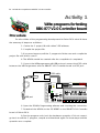
Activity 1
Write programs for testing
RBX-877 V2.0 Controller board
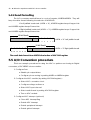
Procedure
For all activities of the programming development for Robo-PICA robot kit have
the summary of steps are as follows :
1. Create the C project file with mikroC IDE software.
2. Compile the project file.
3. If any error happens, edit the C program to fix the error and compile the
project file until all are correct.
4. The HEX file would be created after the compilation is completed.
5. Connect the USB programmer with USB port and connect the ICD2 cable
between the USB Programmer and the RBX-877 V2.0 Controller board at ICD2 jack.
USB Programmer
ICD2 cable
4.8-6V
LCD
BATT
RC7
RxD
DOWNLOAD
POWER
RC4
SDA
RC3
SCL
ICD2
ON
ON
M-1 M-2
SERVO
#1
#2
#3
S+
USB port
RC6
TxD
RA4
RESET
RB0
Robo - PICARRobotR
PICRMicroRobotic
RB0/INT
RA0
RA1
RA2
RA3
RA5
RE0
RE
6. Open the PICkit2TM Programming software and checking the connection.
7. Download the HEX file to the PIC16F887 on the RBX-877 V2.0 Controller
board of Robot-PICA.
8. Run the program and check the hardware operation. If it is not correct,
go back to edit the C program, compile and download again. Do these steps unitl the
operation are complete.
Robotics experiment with PIC microcontrollerl 31
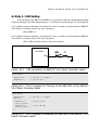
Activity 1-1 LED testing
See the Figure A1-1, RB3 of PIC16F887 is connected to LED via current limited resistor
510Ω. For turning-on this LED must send logic “1” to this port. and send logic “0” for turning-off.
A1.1.1 Write program following the Listing A1-1 then compile and download to RBX-877
V2.0 Robot Controller board. See the operation.
LED at RB3 on.
A1.1.2 Write program following the Listing A1-2 then compile and download to RBX-877
V2.0 Robot Controller board. See the operation.
LED at RB3 will blink with 0.5 second duration.
LED3
21+$.&&%
4*!
!$
4*!
R9
510
Figure A1-1 : LED connection on RBX-877 V2.0 Robot Controller board
void main()
{
TRISB.F3=0;
PORTB.F3=1;
}
// Set RB3 ==> Output
// Turn on RB3
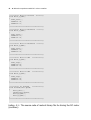
Listing A1-1 : The C program for Turning on the RB3-LED of the RBX-877
V2.0 Robot Controller board
void main()
{
TRISB.F3=0;
// Set RB3 ==> Output
while(1)
{
PORTB.F3=1;
// Turn on RB3
Delay_ms(500);
PORTB.F3=0;
// Turn off RB3
Delay_ms(500);
}
}
Listing A1-2 : The C program for Blinking the RB3-LED of the RBX-877 V2.0
Robot Controller board
32 l Robotics experiment with PIC microcontroller
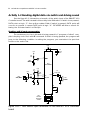
Activity 1-2 Reading digital data via switch and driving sound
See the figue A1-2, it shows the schematic of the switch input of the RBX-877 V2.0
Controller board. The switch tested in this activity is the RA4-switch. If switch is not pressed,
DATA point as logic “1” from pull-up resistor 10kΩ. If switch is pressed, DATA point will
connect to ground. It causes DATA point is logic “0”. PIC16F887 will drive a sound following the activated swtich at RA4 pin.
Reading switch input programming
The easiest way to check this switch being pressed in C program of mikroC compiler is looping and check with IF command. If switch is being pressed, the program will
jump to the following condition. In writing the program, you must select the port that
interface the switch first.
+5V
11
32
C6
0.1µF
50V
+5V
R5
4k7
1
R6
1k
SW2
RESET
MCLR
1+!
21+$.&&%
R7
4k7
+5V
K7
INT/RB0
R9
150
+5V
R8
4k7
6
33
RA4
RC0
15
RB0/INT
C7
10µF 50V
SP1
PIEZO
12
31
CR1
Ceramic
Resonator
20MHz
13
14
Figure A1-2 : RA4 Switch input schematic of the RBX-877 V2.0 Controller
board
Robotics experiment with PIC microcontrollerl 33
Testing
A1.2.1 Write the Listing A1-3. Compile and download the code to RBX-877 board.
A1.2.2 Press the switch at RA4 and observe the operation of the Piezo speaker on the
RBX-877 V2.0 Robot Controller board.
Listen sound from the piezo speaker following the switch pressing.
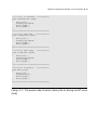
void main()
{
Sound_Init(&PORTC, 0);
while(1)
{
if (!PORTA.F4)
sound_play(250,50);
}
}
// Init Sound
// Test RA4 keypress
// 2kHz sound ON RC0
Listing A1-3 : The C program of reading digital value from the Switch input
at RA4 pin to control the sound generation of Piezo speaker at RC0 pin. The
operation is similar the door chime.
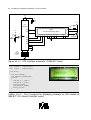
Activity 1-3 Show message on LCD module
The RBX-877 V2.0 Robot Controller board provides the connector to interface
LCD moudule. The schematic diagram is shown in the Figure A1-3. User must use this
information to define in the C program for mikroC compiler knows the port pin that use
in this interface.
When interfacing, you wil require 6 port pins which includes the RD2 for RS pin of
LCD module, RD3 for E pin and RD4 to RD7 for data pin D4 to D7 in 4-bit interface mode.
The R/W pin of LCD is connected to ground for only writing all data to LCD. With this
connection, help developers to make the C code for interfacing the LCD module easier.
Because you can use the LCD built-in function of mikroC compiler; Lcd_Init(&PORTD).
Testing
A1.3.1 Write the Listing A1-4. Compile and download the code to RBX-877 V2.0 Robot
Controller board.
A1.3.2 Observe the operation.
At LCD module show message Innovative on the upper line and Experiment on
the lower line. If need to use the back-light LED, put jumper at LCD backlight position.
34 l Robotics experiment with PIC microcontroller
+5V
11
32
C6
0.1µF
50V
+5V
1+!
21+$.&&%
RD2
+5V
RD3
R5
4k7
SW2
4-5-6
1
R6
1k
MCLR
RD7
RD6
RD5
RD4
JP1
21
4
22
6
30
RS
E
BLA
DSP1
LCD 16x2 (back light option)
+V
Vo
D7 D6 D5 D4 D3 D2 D1 D0 R/W
14 13 12 11 10
9
8
7
5
BLK GND
15
2
R13
16 47
BACK LIGHT
ON
1
3
VR1
10k
BRIGHTNESS
29
28
27
12
31
CR1
Ceramic
Resonator
20MHz
13
14
Figure A1-3 : LCD interface schematic of RBX-877 board
char *text1 = "Innovative";
char *text2 = "Experiment";
void main()
{
Lcd_Init(&PORTD);
Lcd_Cmd(LCD_CURSOR_OFF);
while(1)
{
Lcd_Out(1,1,text1);
Lcd_Out(2,1,text2);
Delay_ms(5000);
Lcd_Cmd(LCD_CLEAR);
Delay_ms(500);
}
}
Listing A1-4 : The C program for displaying message on LCD module of
RBX-877 V2.0 Robot Controller board
INNOVATIVE EXPERIMENT
Robotics experiment with PIC microcontroller l 35
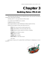
Chapter 3
Building Robo-PICA kit
This chapter describes about how to building the Robo-PICA robot kit. The features
of Robo-PICA robot kit are as follows :
l Driving with DC motor gearboxes and Track wheel
l Controlled by PIC16F887 microcontroller
l 8KWords program memory
l Re-programmable at least 10,000 times for flash program memory
l Support many types of sensor and detector such as
ZX-01 Switch input board for attacking detection,
ZX-03 Infrared Reflector for line tracking and area,
ZX-IRM Infrared receiver module for remote controlling,
GP2D120 Infrared distance sensor,
SRF05 Ultrasonic sensor,
CMPS03 Digital compass,
Memsic2125 Accelerometer sensor
and more...
l Provides Character LCD moduel 16x2 and LED status for displaying the robot
operation.
36 l Robotics experiment with PIC microcontroller
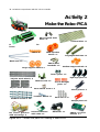
Activity 2
Make the Robo-PICA
Short angled shaft
base x 2
Universal Plate x 1
RBX-877 PIC16F887 controller
board
Hub x 6
Main sprocket
wheel x 2
Long angled shaft base x 2
Metal axel x 3
30mm. Hex
standoffs x 3
Large support wheel x 2
Medium support wheel x 2
3mm. spacer x 2
Right angle joiners x 3
30-joint track wheel x 2
Thumb screw x 3
10-joint track wheel x 4
3x10mm. Screw x 15
3-hold Straight
joiner x 2
2mm. Wood screw x 2
3x15mm. Screw x 1
Obtuse joiners x 3
3mm. Nut x 11
Straight joiners x 3
DC motor gearbox
with mounting x 2
Infrared reflector
with cable x 2
GP2D120 x 1
Figure A2-1 : Shows the parts for making a Robo-PICA.
38kHz receiver
module x 1
Robotics experiment with PIC microcontroller l 37
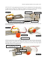
A2.1 Fix 2 of DC motor gearboxes at the base. Turn the extrude side of the right gearbox
out side shown in Figure A2-2. Tighten the 3x10mm. screws from bottom side to fix this
gearbox. Leave the inside hole of the left gearbox. Do not tighten the screw.
Leave the
gearboxs hole
Figure A2-2
3x10mm. screw
Top side
Bottom side
Turn the extrude side to outside
and tight a screw from bottom side
Figure A2-3
3x10mm. screw
A2.2 Insert the main sprocket to the gearbox’s shaft and fix with 2mm. Wood screw. Do
both DC gearboxes.
Figure A2-4
Top side
Main sprocket
Figure A2-5
2mm. Wood screw
A2.3 Put up side down. Attach the Long angled shaft base with the base at the specific
position as shown in the figure A2-6. Tighten the 3x10mm. screw to a leave hole from step
A2.1.Next, tight a 3x10mm. screw and 3mm. nut to fix the second hole of the Long angled
shaft base as shown in the figure A2-6.
Hole for tightening a 3x10mm.
screw and 3 mm. nut
3x10mm. screw
Bottom side
Long angled
shaft base
Figure A2-6
38 l Robotics experiment with PIC microcontroller
A2.4 Attache the rest of Long angled shaft base with a base by inserted the 3x10mm. screws
from top side through the hole and tighten with 3mm. nuts following the Figure A2-7.
3mm. nut
3mm. nut
Long angled
shaft base
Bottom side
3mm. nut
Figure A2-7
A2.5 Turn the base over. Attach 2 of the Short angled shaft bases at the front of the robot’s
base as shown in the Figure A2-8 by inserted the 3x10mm. screws from bottom side through
the shaft bases’ holes and tighten with 3mm. nuts. Tighten the screw on the inside hole.
Leave the outside holes.
3mm. nut
Top side
Leave holes
Top side
3mm. nut
Short angled
shaft base
Figure A2-8
A2.6 Fix a Hexagonal standofff at bottom side of base by put upside down and tight a
3x10mm. screw through a left corner hole and the Right angle joiner.
Figure A2-9
3x10mm. screw
Bottom side
Turn the bottom side up
3x10mm. screw
Right angle joiner
30mm. Hexagonal
standoff
Right
gearbox
A left corner
back side hole
of the base
Top side of
the base
Hexagonal standoff
Right angle
joiner
Robotics experiment with PIC microcontroller l 39
A2.7 At front side, attach 2 of the Hexagonal standoffs. Insert the 3x10mm. screw through
the 3-hole straight joiner and the leave hole of the short angled shaft base from step A2.5
to fix with the 30mm. Hexagonal standoffs.
3-Hole Straight joiner
Bottom side
3x10mm. screw
Short angled
shaft base
30mm. Hexagonal Standoff
Figure A2-10
A2.8 With the board still upside down, Insert the metal axel into the holes of the long
angled shaft in the hole positions of 2 and 6 as shown in the Figure A2-11. Place the Medium track support wheels over the metal axel. Insert the hubs over the wheels so that
the wheels and the axels are connected tightly. Turn up the base. Insert the 3rd metal
axel into the holes of the short angled shaft. Place the Large support wheel over the axel.
Insert the hubs over the wheels so that the wheels and the axels are connected tightly.
Metal axel
Hub
Hub
Hub
Medium supprot wheels
Large supprot wheels
6th hole
2nd hole
Hub
Metal axel
Figure A2-11
40 l Robotics experiment with PIC microcontroller
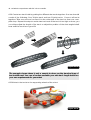
A2.9 Create two track belts by putting the different size tracks together. One track would
consist of the following: One 30-joint track and two 10-joint tracks. Connect all tracks
together. Take one end and connect it to the other end of the track to form one complete loop. Repeat the steps to make two track sets. If the track is too tight or loose, you
can either adjust the length of the track or adjust the position of the short angled shaft
base until the track has a good fit.
Figure A2-12
The example shown above is only a sample to show you the standard type of
track width used. You can of course assemble your own track length based on
your own requirements for your robot.
A2.10 Attach the tracks to the supporting wheels of the robot.
Figure A2-13
Robotics experiment with PIC microcontroller l 41
A2.11 Attach the RBX-877 V2.0 controller board on top of robot’s chasis. Please fix the
board with the Power swtch at the side where the DC motor gearboxes are. Secure with
3 Thumb screws at the ends.
Thumbscrews
Thumbscrew
Figure A2-14
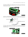
A2.12 Attach a ZX-IRM 38kHz Receiver module sensor board with the Obtuse joiner using
3x15mm. screw and 3mm. nut. Insert a Straight joiner at another end of the Obtuse joiner.
3x15mm. screw
Obtuse joiner
JST3AA-8 sensor cable
Straight joiner
Figure A2-15
A2.13 Attach a Right angle joiner at the center hole of the back side (Power switch side)
of the RBX-877 V2.0 controller board by a 3x10mm. screw and 3mm. nut for attaching the
ZX-IRM sensor board.
Right angle joiner
3x10mm. screw
Figure A2-16
42 l Robotics experiment with PIC microcontroller
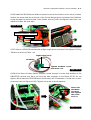
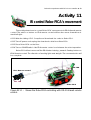
A2.14 Connect the ZX-IRM structure from step A2.12 to the Right angle joiner on the RBX-877
V2.0 controller board from step A2.13. Plug in the Zx-IRM sensor cable to RB0/INT connector.
ZX-IRM
RB0
Figure A2-17
A2.15 Plug the DC motor gearboxes cable to Motor connectors. The right motor is connected to the white M-2 output and left motor is connected to the black M-1 output.
However the motor’s pole (white or black connector) can be changed depending on
the programming and mission. Normally, refer from the motor output’s indicator, if both
light green, it means the forward movement and both light red mean the backward
movement. You can change later if the operation incorrect.
M-1 motor
M-2 motor
Figure A2-18
Robotics experiment with PIC microcontroller l 43
A2.16 Install the ZX-03 Infrared reflector sensor board at the bottom of the robot’s chasis.
Attach the sensor with the end hole of the 3-hole Straight joiner by inserted the 3x10mm.
screw through the sensor board, 3mm. plastic spacer, joiner and tighten with 3mm. nut.
Install both side; left and right.
Figure A2-19
Infrared reflector sensors
3mm. nut
3mm. spacer
Figure A2-20
A2.17 Attach a GP2D120 module with a Right angle joiner as shown in the Figure A2-21 by
3x10mm. screw and 3mm. nut.
Right angle joiner
GP2D120
Tighten 3x10mm. screw
with 3mm. nut
Figure A2-21
A2.18 At the front of robot, insert a 3x10mm. screw through a center hole position of the
RBX-877V2.0 board and 3mm. nut from top side as shown in the Figure A2-22. Do not
tighten. Next, Insert the GP2D120 structure from step A2.17 between a screw and controller board ( see the Figure A2-23). Tighten the screw to fix all together.
Insert the
GP2D120
structure
and tighten
the screw
to fix it.
Figure A2-22
Figure A2-23
44 l Robotics experiment with PIC microcontroller
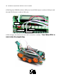
A2.19 Plug the GP2D120 cable to RA2 port, the left ZX-03 sensor’s cable to RA0 port and
the right ZX-03 sensor’s cable to RA1 port.
ZX-IRM
Right ZX-03
GP2D120
Left ZX-03
A2.20 Arrange all cables and check all connection carefully.
now ready for programing.
INNOVATIVE EXPERIMENT
Your Robo-PICA is
Robotics experiment with PIC microcontrollerl 45
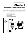
Chapter 4
Simple robot ’s programming control
The first thing is to control robot Movement. The heart of this movement is DC
motor circuit. In Robo-PICA has DC motor gearbox in driving. The Figure 4-1 shows the
DC motor circuit. PIC16F887 assigns 6 port pins to connect the DC motor driver circuit
for driving 2 motors.
The motor driving mechanism are divided into 4 types as follows :
(1) Clockwise motor driving
(2) Anti-clockwies motor driving
(3) Motor’s shaft is free
(4) Motor’s shaft is locked or Braked
+5V
+5V
11
R5
4k7
SW2
RESET
1
R6
1k
32
C6
0.1µF
50V
K18A-K18B
MOTOR-A
MCLR
16
RD0
RD1
19
2
20
7 2A
RC2/CCP1 17
RB1
RB2
RC1/CCP2
1
1A
Vcc1
12EN
34
15 4A
35
10
16
9
8
1Y 3
2Y
3Y
31
+
+
R11
2k2
DIRECT
LED4
DIR. #A
6
IC4
14
4Y
L293D
LED5
DIR. #B
11
R12
2k2
3A
INVERT
34EN
12
13
C8
0.1µF 50V
+5V +Vm
IC3
PIC16F887
INVERT
13 12 5
4
+
C9
0.1µF 50V
K19A-K19B
MOTOR-B
+
DIRECT
14
CR1
Ceramic
Resonator
20MHz
Figure 4-1 : The DC motor driver schematic of RBX-877 V2.0 board
46 l Robotics experiment with PIC microcontroller
12EN/34EN pin
1A/3A pin
2A/4A pin
Motor operation
0
X
X
Shaft free
1
0
0
Shaft locked or Brake
1
0
1
Clockwise turning
1
1
0
anti-clockwise turning
1
1
1
Shaft locked or Brake
X means logic "0" or "1"
Table 4-1 : Shows logic signal to control motor direction
The heart of DC motor driver circuit is the L293D H-Bridge driver (may be replaced
by SN754410). In the Table 4-1 shows all the required signals to control the DC motor
driver circuit.
L293D outputs connects to DC motor gearbox and provides LED status for motor
supply voltage. If power is supplied DIRECTLY, the LED will light up in Green. When it is
opposite, if red LED lights up, it means the supply voltage is INVERTED. Builders can use
the different color for defining direction. In other words, if red LED are turned on, the
robot will be moving backwards. If the green LED are turned on, the robot will be moving forwards.
4.1 Motor library file
For better performance and ease of programming, we make the library for driving
and movement controls for the DC motors. It is the motor.h library file. The souce code of
this library is shown in Listing 4-1.
You can use simple text editor t ocreate this library and save as .h file or open
mikroC IDE to create this file. After that copy this library file to the library folder of mikroC
software. The location is C:\Program Files\Mikroelektronika\mikroC\include. You must
copy the motor.h file to this folder. Because the complier will link to this folder for including any library.
motor.h library file consists of many functions of movement control. Include :
Motor_Init : Initial the micrococontroller port pin for interfacing the DC
motor driver circuit.
Change_Duty : Control the motor’s speed.
Motor_A_FWD : Drive motor A (M-1 output) to forward direction (LED indicates of M-1 lights in green).
Robotics experiment with PIC microcontrollerl 47
char motor_duty_= 127;
char motor_init_=0;
//
//
//
//
*** Motor A
PD0 ====>
PD1 ====>
PC2 ====>
*****
1A
1B
1E (PWM1)
//
//
//
//
*** Motor B
PB1 ====>
PB2 ====>
PC1 ====>
*****
2A
2B
2E (PWM2)
// Defalt PWM 50%
// Status initial
//****************************************************
//********** Initial Motor Function ******************
//****************************************************
void Motor_Init()
{
if (motor_init_==0)
// First time ?
{
motor_init_=1;
// Status
ANSELH.F0=0;
// RB1 ==> Digital IO
ANSELH.F2=0;
// RB2 ==> Digital IO
TRISB.F1=0;
// Motor B 2A
TRISB.F2=0;
// Motor B 2B
TRISD.F0=0;
// Motor A 1A
TRISD.F1=0;
// MOtor A 1B
Pwm1_Init(5000);
// Initail PWM 1E
Pwm2_Init(5000);
// Initail PWM 2E
}
}
//****************************************************
//****************************************************
//********** Control Duty Cycle *********************
//****************************************************
void Change_Duty(char speed)
{
if (speed != motor_duty_)
// Check Same old speed
{
motor_duty_=speed;
// Save for old speed
Pwm1_Change_Duty(speed);
// Motor A
Pwm2_Change_Duty(speed);
// Motor B
}
}
//****************************************************
/********** Motor A Forward ********/
void Motor_A_FWD()
{
Pwm1_Start();
PORTD.F0 =0;
PORTD.F1 =1;
}
/************************************/
Listing 4-1 : The source code of motor.h library file for driving the DC motor
(continue)
48 l Robotics experiment with PIC microcontroller
/********** Motor B Forward ********/
void Motor_B_FWD()
{
Pwm2_Start();
PORTB.F1 =0;
PORTB.F2 =1;
}
/************************************/
/********** Motor A Backward *******/
void Motor_A_BWD()
{
Pwm1_Start();
PORTD.F0 =1;
PORTD.F1 =0;
}
/************************************/
/********** Motor B Backward *******/
void Motor_B_BWD()
{
Pwm2_Start();
PORTB.F1 =1;
PORTB.F2 =0;
}
/************************************/
/********** Motor A Off ************/
void Motor_A_Off()
{
Pwm1_Stop();
PORTD.F0 =0;
PORTD.F1 =0;
}
/************************************/
/********** Motor B Off ************/
void Motor_B_Off()
{
Pwm2_Stop();
PORTB.F1 =0;
PORTB.F2 =0;
}
/************************************/
/********** Go Forward
************/
void Forward(char speed)
{
Motor_Init();
Change_Duty(speed);
Motor_A_FWD();
Motor_B_FWD();
}
/************************************/
Listing 4-1 : The source code of motor.h library file for driving the DC motor
(continue)
Robotics experiment with PIC microcontrollerl 49
/********** Go Backward ************/
void Backward(char speed)
{
Motor_Init();
Change_Duty(speed);
Motor_A_BWD();
Motor_B_BWD();
}
/************************************/
/********** Spin Left
*************/
void S_Right(char speed)
{
Motor_Init();
Change_Duty(speed);
Motor_A_FWD();
Motor_B_BWD();
}
/************************************/
/********** Spin Right
************/
void S_Left(char speed)
{
Motor_Init();
Change_Duty(speed);
Motor_A_BWD();
Motor_B_FWD();
}
/************************************/
/********** Stop Motor
************/
void Motor_Stop()
{
Motor_Init();
Change_Duty(0);
Motor_A_Off();
Motor_B_Off();
}
/************************************/
Listing 4-1 : The source code of motor.h library file for driving the DC motor
(final)
50 l Robotics experiment with PIC microcontroller
Motor_B_FWD : Drive motor B (M-2 output) to forward direction (LED indicates of M-2 lights in green).
Motor_A_BWD : Drive motor A (M-1 output) to backward direction (LED
indicates of M-1 lights in red).
Motor_B_BWD : Drive motor B (M-2 output) to backward direction (LED
indicates of M-2 lights in red).
Motor_A_off : Turn off or Stop motor A (M-1 output).
Motor_B_off : Turn off or Stop motor B (M-2 output).
foward : Drives both DC motror to move the Robo-PICA forward.
backward : Drives both DC motror to move the Robo-PICA backward.
S_right : Drives both DC motror to spin the Robo-PICA in right direction.
S_left : Drives both DC motror to spin the Robo-PICA in left direction.
Motor_stop : Stop both DC motror.
Robotics experiment with PIC microcontrollerl 51
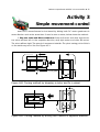
Activity 3
Simple movement control
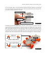
Robo-PICA moves forward or backward by driving both DC motor gearboxes in
same direction and at the same time. If need to turn or rotate, below shows the method :
1. Stop one motor and Drive another one If stop left motor and drive right motor,
the robot will turn left. In the opposite direction, stop right motor and drive left motor.
The robot will turn right. The speed of movement is similar. The pivot turning point of this is
at the stationary track. See the Figure A3-1.
Turning point
Turning point
Figure A3-1 Turning method by stopping a motor and fix a wheel.
Turning point
Turning point
Figure A3-2 Turning method by driving both motors in opposite direction.
52 l Robotics experiment with PIC microcontroller
2. Drive both motors in opposite direction If the left motor drives forward and
right motor drives backward, the robot will rotate right direction. If its in the opposite
direction, the left motor drives backward and right motor drives forward. The robot will
rotate left direction instead. In this method the speed of rotation will be increase 2 times
and less friction. The turning point is center of robot body. See Figure A3-2.
A3.1 Write program following the Listing A3-1 then compile and download to RBX-877
V2.0 Robot Controller board. Turn-off power switch.
#include <motor.h>
void main()
{
Sound_Init(&PORTC, 0);
while(1)
{
Forward(255);
Delay_ms(2000);
sound_play(100,50);
// Init Sound
// Call Forward
// 1 kHz sound ON RC0
S_Left(255);
Delay_ms(800);
sound_play(100,50);
// Call Spin Left
Forward(255);
Delay_ms(2000);
sound_play(100,50);
// Call Forward
S_Right(255);
Delay_ms(800);
sound_play(100,50);
// Call Spin Right
Forward(255);
Delay_ms(2000);
sound_play(100,50);
// Call Forward
Backward(255);
Delay_ms(1000);
sound_play(100,50);
Motor_Stop;
// Call Backward
// 1 kHz sound ON RC0
// 1 kHz sound ON RC0
// 1 kHz sound ON RC0
// 1 kHz sound ON RC0
// 1 kHz sound ON RC0
// Stop all
}
}
Listing A3-1 The movement program demonstration of Robo-PICA
Robotics experiment with PIC microcontrollerl 53
A3.2 Remove the downlaod cable from Robo-PICA. Place the robot on the floor. Turnon power to run the program. See the operation.
The robot will move forward 2 seconds and spin left 0.8 second and foward 2
seconds again. Next, it will spin right 0.8 second to change the direction and forward
2 seconds, moves backward 1 second and stop movement finally. In each changing
movement, thr robot will beep a sound to report the operation.
However it is possible the robot moves in an incorrect direction. If this happens,
pleae check the motor cable connection. You can change the motor connection
from black to white connector and white to black connector in each motor output.
You can see the LED indicator of DC motor output. During forward movement,
both LEDs must light Green color. In backward movement, both LEDs light Red color.
Must change until the movement direction is corrected and remember or fix the correct connection for all activities onwards.
This is the limitation of malfunctioning, We do not know about the correct pole
of DC motor. But we can control and fix with hardware and software via DC motor
control circuit. This problem can be easily fixed and it is important to know and
understading this.
E
Because the robot use battery to power source. In during the battery level is
full power and not full, the speed of movement is not equal. It cause the distance from movement may be not equal. It is limitation of all robot that use
open loop movement control.
54 l Robotics experiment with PIC microcontroller
Activity 4
Speed control of Robo-PICA
Robo-PICA can control the speed movement by send the signal to the enable
pin (EN) of motor driver IC, L293D. Refer the figure 4-1 (in this chapter), EN pin of L293D is
connected to RC2/CCP1 and RC1/CCP2 port pins of PIC16F887. Both port pins are PWM
output port. Builders can write the program to control the PWM output signal for adjustment motor speed.
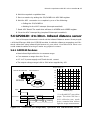
PWM operation
Normal driving motor technique is apply the voltage to motor directly. The motor
works in full speed. Sometime this speed faster. Then the simple method to control motor
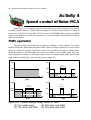
speed is control the voltage applied to motor. The populate technique is PWM (pulsewidth modulation). This technique will control the width of the positive pulse. The voltage is applied to motor as average value. Ratio of positive pulse width and totally
pulse width is called Duty cycle. Its unit is percentage (%)
Volt
Volt
50%
duty cycle
4.8V
4.8V
2.4V
Average voltage = 2.4V
Time
Time
(A)
(B)
Volt
Volt
25%
duty cycle
75%
duty cycle
4.8V
4.8V
3.6V
1.2V
Average voltage = 3.6V
(C)
Time
Average voltage = 1.2V
(D)
Figure A4-1 : Shows average voltage output of PWM
(A) Full volatge apply.
(B) 50% duty cycle PWM
(C) 75% duty cycle PWM
(D) 25% duty cycle PWM
Time
Robotics experiment with PIC microcontrollerl 55
#include <motor.h>
char i;
void main()
{
Forward(255);
while(1)
{
Delay_ms(2000);
Pwm1_Change_Duty(220);
Pwm2_Change_Duty(255);
Delay_ms(5000);
Pwm1_Change_Duty(255);
}
}
// Motor Forward
// Motor A
// Motor B
85% Duty
100% Duty
// Motor A 100% Duty
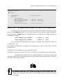
Listing A4-1 : The speed control program for Robo-PICA by using PWM.
For Robo-PICA, we prepare the speed control with PWM technique via software by the motor.h library file. You can see detail in motor.h sourcecode in Listing 4-1
(in this chapter). motor.h library has PWM function for supporting 2 PWM modules of
PIC16F887 as follows :
Pwm1_Change_Duty(speed);
// Motor A
Duty
Pwm2_Change_Duty(speed);
// Motor B
Duty
You can put the required duty cycle value in (speed). The range is 0 to 255 for 0
to 100% duty cycle.
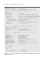
A4.1 Write the Listing A4-1. Compile and download the code to Robo-PICA. Turn-off
power switch.
A4.2 Remove the downlaod cable from Robo-PICA.
A4.3 Place the robot on the floor. Turn-on power to run the program. See the operation.
The Robo-PICA robot will move forward fastest in 2 seconds and spin left
5 second. After that the robot will move foraward with fastest speed again. The robot
will move this routine all times.
INNOVATIVE EXPERIMENT
E
The suitable PWM duty cycle value for driving the robot is more than 70%.
If select the less value, the robot has not torque more enough for turning
or rotation.
56 l Robotics experiment with PIC microcontroller
Robotics experiment with PIC microcontrollerl 57
Chapter 5
Contactless object detection
The one of most important function of mobile robot is interfacing the sensors. RoboPICA can interface with many type of sensors. Because it has both digital and analog
inputs. PIC16F887 the main microcontroller of Robo-PICA has many ports. We assign 9
programmable port pins for supporting the analog and digital sensors. In addtion 2 types
of serial coomunication ports; UART and I2C bus.
In this chapter, we will concentrate to interfacing with angalog sensors. The RoboPICA kit provides 2 kinds of analog sensors ; GP2D120 the infrared distance sensor and
ZX-03 Infrared Reflector sensors for line tracking activities.
5.1 PIC16F887’s A/D converter
PIC16F887 microconttroller contains 14-channel 10-bit analog to digital converter
module (ADC). All analog input ports can be configured to digital input and output. They
include RA0 to RA3, RA5, RB0 to RB5 and RE0 to RE2.
The Analog-to-Digital Converter (ADC) allows conversion of an analog input signal
to a 10-bit binary representation of that signal. This device uses analog inputs, which are
multiplexed into a single sample and hold circuit. The output of the sample and hold is
connected to the input of the converter. The converter generates a 10-bit binary result
via successive approximation and stores the conversion result into the ADC result registers
(ADRESL and ADRESH).
The ADC voltage reference is software selectable to either VDD or a voltage applied to the external reference pins.
5.2 ADC register
The important register of this module are ADCON0 and ADCON1 register. The
ADCON0 is used to select the analog pin fucntion and ADCON1 is used to select the
result data format and voltage reference.
58 l Robotics experiment with PIC microcontroller
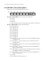
5.2.1 ADCON0 : A/D Control register 0
Detail of each bit in ADCON0 register is shown below.
>EJ
%
$
"
!
ADCS1 ADCS0 CHS3
CHS2
CHS1
R/W-0
R/W-0
R/W-0
R/W-0
#
R/W-0
CHS0
GO/
DONE
ADON
R/W-0
R/W-0
R/W-0
bit 7 and 6 - ADCS1, ADCS0 : A/D Conversion Clock Select bits
00 = FOSC/2
01 = FOSC/8
10 = FOSC/32
11 = FRC (clock derived from a dedicated internal oscillator = 500 kHz max)
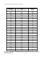
bit 5 to 2 - CHS3 to CHS0 : Analog Channel Select bits
0000 = AN0 (RA0 pin)
0001 = AN1 (RA1 pin)
0010 = AN2 (RA2 pin)
0011 = AN3 (RA3 pin)
0100 = AN4 (RA5 pin)
0101 = AN5 (RE0 pin)
0110 = AN6 (RE1 pin)
0111 = AN7 (RE2 pin)
1000 = AN8 (RB2 pin - reserve for DC motor circuit of the RBX-877V2.0 Robot
Controller board)
1001 = AN9 (RB3 pin - reserve for LED monitor of the RBX-877V2.0 Robot
Controller board)
1010 = AN10 (RB1 pin - reserve for DC motor circuit of the RBX-877V2.0 Robot
Controller board)
1011 = AN11 (RB4 pin - reserve for servo motor output of the RBX-877V2.0
Robot Controller board)
1100 = AN12 (RB0 pin - alternative function wih External Interrput and Swtich
of the RBX-877V2.0 Robot Controller board)
1101 = AN13 (RB5 pin - reserve for servo motor output of the RBX-877V2.0
Robot Controller board)
1110 = CVREF
1111 = Fixed Ref (0.6 volt fixed reference)
Robotics experiment with PIC microcontrollerl 59
bit 1- GO/DONE: A/D Conversion Status bit
1 = A/D conversion cycle in progress. Setting this bit starts an A/D conversion
cycle. This bit is automatically cleared by hardware when the A/D
conversion has completed.
“0” = A/D conversion completed/not in progress
bit 0 - ADON: ADC Enable bit
1 = ADC is enabled
0 = ADC is disabled and consumes no operating current
5.2.2 ADCON1 : A/D Control register 1
Detail of each bit in ADCON1 register is shown below.
>EJ
%
$
ADFM
-
R/W-0
U-0
#
"
VCFG1 VCFG0
R/W-0
R/W-0
!
0 = Left justified
bit 6 - Unimplemented: Read as “0”
bit 5 - VCFG1: Voltage Reference bit
1 = VREF- pin
0 = Vss
bit 4 - VCFG0: Voltage Reference bit
1 = VREF+ pin
0 = VDD
bit 3 to 0 - Unimplemented: Read as ‘0’
-
-
-
-
U-0
U-0
U-0
U-0
bit 7 - ADFM: A/D Conversion Result Format Select bit
1 = Right justified
60 l Robotics experiment with PIC microcontroller
5.2.3 ANSEL : Analog Select register
The ANSEL register is used to configure the Input mode of an I/O pin to analog.
Setting the appropriate ANSEL bit high will cause all digital reads on the pin to be read as
‘0’ and allow analog functions on the pin to operate correctly.
Detail of each bit in ANSEL register is shown below.
bit
%
$
#
"
!
ANS7
ANS6
ANS5
ANS4
ANS3
R/W-1
R/W-1
R/W-1
R/W-1
R/W-1
ANS2
ANS1
ANS0
R/W-1
R/W-1
R/W-1
bit 7 to 0 - ANS7 to ANS0 : Analog Select bits
Analog select between analog or digital function on pins AN<7:0> or RE2,
RE1, RE0, RA5, RA3, RA2, RA1 and RA0 respectively.
1 = Analog input. Pin is assigned as analog input (default).
0 = Digital I/O. Pin is assigned to port or special function.
5.2.4 ANSELH : Analog Select High register
The ANSELH register is used to configure the Input mode of an I/O pin to analog.
Setting the appropriate ANSELH bit high will cause all digital reads on the pin to be read
as ‘0’ and allow analog functions on the pin to operate correctly. The port pins which are
controlled by this register consists of AN8 to AN13 (RB2, RB3, RB1, RB4, RB0 and RB5).
Detail of each bit in ANSELH register is shown below.
bit
%
$
-
-
U-0
U-0
#
"
!
ANS13 ANS12 ANS11 ANS10 ANS9
ANS8
R/W-1
R/W-1
R/W-1
R/W-1
R/W-1
R/W-1
bit 7 and 6 - Unimplemented: Read as ‘0’
bit 5 to 0 - ANS13 to ANS8 : Analog Select bits
Analog select between analog or digital function on pins AN<13:8> or RB5,
RB0, RB4, RB1, RB3 and RB2 respectively.
1 = Analog input. Pin is assigned as analog input.
0 = Digital I/O. Pin is assigned to port or special function.
Robotics experiment with PIC microcontrollerl 61
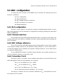
5.3 ADC configuration
For using the ADC module of PIC16F887 microcontroller the following functions
must be considered:
l Port configuration
l Channel selection
l ADC voltage reference selection
l ADC conversion clock source
l Results formatting
5.4.1 Port configuration
The ADC can be used to convert both analog and digital signals. When converting analog signals, the I/O pin should be configured for analog by setting the associated
TRIS and ANSEL bits.
5.4.2 Channel selection
The CHS bits of the ADCON0 register determine which channel is connected to the
sample and hold circuit. When changing channels, a delay is required before starting the
next conversion.
5.4.3 ADC Voltage reference
The VCFG bits of the ADCON0 register provide independent control of the positive
and negative voltage references. The positive voltage reference can be either Vdd or
an external voltage source. Likewise, the negative voltage reference can be either Vss or
an external voltage source.
For the RBX-877V2.0 Robot Controller board will select the positive reference to
+5V and negative reference at ground or Vss.
5.4.4 Conversion Clock
The source of the conversion clock is software selectable via the ADCS bits of the
ADCON0 register. There are four possible clock options:
l FOSC/2 : for 20MHz clock, TAD = 100ns
l FOSC/8 : for 20MHz clock, TAD = 400ns
l FOSC/32 : for 20MHz clock, TAD = 1.6µs
l FRC (dedicated internal oscillator) : TAD = 2 to 6µs
The time to complete one bit conversion is defined as TAD. One full 10-bit conversion requires 11 TAD periods.
62 l Robotics experiment with PIC microcontroller
5.4.5 Result formatting
The A/D converter result will store in a pair of regeter; ADRESH:ADRESL. They will
keep the data format following the selection of ADFM bit.
If Left justified is selected (ADFM = ‘0’), ADRESH register keeps 8 upper bits
and ADRESL register keeps 2 lower bits.
If Right justified is selected (ADFM = ‘1’), ADRESH register keeps 2 upper bits
and ADRESL register keeps 8 lower bits.
10-bit Result
b b b b b b b b b b 0 0 0 0 0 0
# " ! '
&
%
$
#
"
!
ADFM = “0” Left justified result
10-bit Result
0 0 0 0 0 0 b b b b b b b b b b
# " ! '
&
%
$
#
"
!
ADFM = “1” Right justified result
The result data format from ADFM bit selection of ADCON1 register
5.5 A/D Conversion procedure
This is an example procedure for using the ADC to perform an Analog-to-Digital
conversion pf PIC16F887 microcontroller:
1. Configure Port:
l
Disable pin output driver
l
Configure pin as analog by setting ANSEL or ANSELH register
2. Configure the ADC module (by setting ADCON0 register) :
l
Select ADC conversion clock
l
Configure voltage reference
l
Select ADC input channel
l
Select result format by setting ADCON1 register
l
Turn on ADC module
3. Configure ADC interrupt (optional):
l
Clear ADC interrupt flag
l
Enable ADC interrupt
l
Enable peripheral interrupt
l
Enable global interrupt.
Robotics experiment with PIC microcontrollerl 63
4. Wait the required acquisition time.
5. Start conversion by setting the GO/DONE bit in ADCON0 register.
6. Wait for ADC conversion to complete by one of the following:
l
Polling the GO/DONE bit
l
Waiting for the ADC interrupt (interrupts enabled)
7. Read ADC Result. The result data will store in ADRESH and ADRESL register.
8. Clear the ADC interrupt flag (required if interrupt is enabled).
5.6 GP2D120 : 4 to 30cm. Infrared distance sensor
One of the special sensors in robotics is the Infrared Distance sensor. Some people
call it the IR Ranger. With the GP2D120 module, it adds the distance measuring and Obstacle detection using infrared light feature to your robot. Your Robo-PICA robot can
avoid obstacles without having to make any physical contact.
5.6.1 GP2D120 features
l
Uses Infrared light reflection to measure range
l
Can measure a range from 4 to 30 cm.
l
4. 5 to 5 V power supply and 33mA electric current
l
The output voltage range is 0.4 to 2.4V when supplied by +5V
Output voltage (V)
Infrared LED transmitter
2.8
Infrared Receiver
2.4
2.0
1.6
/2 , 1.2
0.8
Vout GND
Vcc
0.4
0
Supply
Vout
4
8
12
16
20
24
28
32
Distance (cm)
38.3±9.6 ms
Measurement
0
1st measure
Not stable
2nd measure
1st output
5 ms
n measure
2nd output
n output
* Use Kodak R-27 gray-white
paper. The white side has a
90% reflection rate, made
from a material that reflects
light for range measurement.
Figure 5-1 : GP2D120 pin assignment, operation and characteristic curve
64 l Robotics experiment with PIC microcontroller
GP2D120 Infrared Ranger module has 3 terminals: Power input (Vcc), Ground (GND)
and Voltage output (Vout). To read the voltage values from the GP2D120, you must wait
till after the acknowledgement period which is around 32 to 52.9 ms.
The output voltage of GP2D120 at a range of 30 cm and +5V power supply is between 0.25 to 0.55V, with the mean being 0.4V. At the range of 4 cm., the output voltage
will change at 2.25V± 0.3V.
5.6.2 How the IR Ranger Module works
Measuring range can be done in many ways. The easiest to understand is through
ultra sonic where sound waves are sent to the object and the time it takes to reflect back
is measured. This is because sounds waves do not travel fast, and can be measured by
present day equipment. However, in the case of infrared light, the time it takes to hit an
obstacle and reflect back can not be measured because infrared light travels fast. No
measurement equipment is available yet. Therefore, the following theory must be used.
The infrared light is sent out from a transmitter to the object in front, by passing
through a condense lens so that the light intensity is focused on a certain point. Refraction occurs once the light hits the surface of the object. Part of the refracted light will be
sent back to the receiver end, in which another lens will combine these lights and. determine the point of impact. The light will then be passed on to an array of photo-transistors.
The position in which the light falls can be used to calculate the distance (L) from the
transmitter to the obstacle using the following formula:
Object
L
A
F
Transmit LED
GP2D120
Photo array
X
Robotics experiment with PIC microcontrollerl 65
L F
=
A X
Therefore, L equals
L=
F×A
X
Thus, the distance value from the phototransistors will be sent to the Signal Evaluation Module before it is changed to voltage, resulting in a change of voltage according
to the measured distance.
5.6.3 Reading GP2D120 with A/D converter
The GP2D120’s output voltage will change acoording to the detection distance.
For example, Vout 0.5V is equal 26cm. distance and Vout 2V is equal 6cm. distance. The
table 5-1 shows the summary of GP2D120’s Vout and Distance relation.
For interfacing with A/D converter module within microcontroller, the result is raw
data from the A/D conversion. The user will need to use the software to convert the raw
data to the exact distance. You can calculate the approximate distance from the formular
below.
4=
'"
−
8+#
Thus, R as Distance in Centimetre unit
V as Digital data from A/D conversion
For example, see the Table 5-1. The raw data from conversion is 307. It is equal
8cm. distance.
Warning for the signal cable of the GP2D120
The GP2D120 module has a different pin arrangement then that of the MicroCamp board,
even though it looks similar. Therefore, a special signal cable has already been connected
to the GP2D120 module. The user just needs to connect the other end of the cable to the
connection points of the MicroCamp board. DO NOT remove the cable from the module,
and do not replace it with signal cables from other sensor modules.
66 l Robotics experiment with PIC microcontroller
GP2D120
output voltage (V)
10-bit
A/D converter result
Distance
(cm.)
0.4
0.5
0.6
0.7
82
102
123
143
32
26
22
19
0.8
0.9
1.0
1.1
1.2
164
184
205
225
246
16
14
13
12
11
1.3
1.4
1.5
1.6
1.7
266
287
307
328
348
10
9
8
8
7
1.8
1.9
2.0
2.1
369
389
410
430
7
6
6
6
2.2
2.3
2.4
2.5
2.6
451
471
492
512
532
5
5
5
5
4
Table 5-1 : The relation of GP2D120 output voltage, A/D converter result and
Measured distance.
Robotics experiment with PIC microcontrollerl 67
Activity 5
Reading the analog signal
This activity introduces the simple experiment about reading the analog signal.
The simple Variable resistor or Potentiometer is used to analog voltage source and plug
into the analog input port of PIC16F887. You make the simple C code to read the result
from ADC module inside PIC16F887 to display on LCD module.
A5.1 Write the Listing A5-1. Compile and download the code to RBX-877 V2.0 Robot Controller board.
A5.2 Plug the ZX-POTH; potentiometer sensor to RA3 port pin of RBX-877 V2.0 Robot Controller board.
A5.3 Run the program. Adjust the potentiometer and see the result at LCD screen on the
RBX-877 V2.0 Robot Controller board.
LCD module shows message SENSOR1 = xxx (xxx as 0 to 1023).
/***********************************/
/***** Show ADC from RA1 to LCD ***/
/***********************************/
char data_[6];
int x;
void main()
{
Delay_ms(1000);
Lcd_Init(&PORTD);
ANSEL = 0xFF;
//
TRISA = 0xFF;
//
Lcd_Cmd(LCD_CURSOR_OFF);
//
Lcd_Out(1,1,"SENSOR1 = ");
//
ADCON0=0b11001101;
//
while(1)
{
ADCON0.GO=1;
while(ADCON0.GO);
x= (ADRESH*4)+(ADRESL/64);
WordToStr(x,data_);
Lcd_Out(1,10,data_);
Delay_ms(100);
}
}
PORTA ==> Analog
PORTA ==> input
LCD cursor off
Show Text
Select Analog1 RC_Mode and ADON
Listing A5-1 : The ADC demonstration program for reading the sensor value
68 l Robotics experiment with PIC microcontroller
Activity 6
Testing GP2D120
A6.1 Write the Listing A6-1. Compile and download the code to Robo-PICA.
A6.2 Plug the GP2D120 sensor to RA2 port pin of Robo-PICA. (ready from building activty 3).
A6.3 Run the program. Place some object at the front of GP2D120 module. Observe the
LCD operation.
A6.4 Adjust the distance of the object from GP2D120 sensor and observe the result.
From testing, you will found the GP2D120 can detect the object in range 4 to 30cm.
int Adc;
char txt[6];
void Read_Adc()
{
ADCON0=0b11001001;
ADCON0.GO=1;
while(ADCON0.GO);
Adc=(ADRESH*4)+(ADRESL/64);
}
void main()
{
Delay_ms(1000);
Lcd_Init(&PORTD);
Lcd_Cmd(LCD_CURSOR_OFF);
Lcd_Out(1,1,"Raw Data= ");
while(1)
{
Read_Adc();
WordToStr(Adc,txt);
Lcd_Out(1,10,txt);
if (Adc<90)
{
Lcd_Out(2,1,"Out of Range");
}
else
{
Adc = (2914/(Adc+5))-1;
WordToStr(Adc,txt);
Lcd_Out(2,1,"In CM=
");
Lcd_Out(2,6,txt);
}
Delay_ms(1000);
}
}
//
//
//
//
Select Analog2 RC_Mode and ADON
Start Convert
Wait Until Convert Complete
10 bit Data ==> Adc
// Initial LCD
// LCD Cursor OFF
// Show Fisrt Line Text
// Convert To Show on LCD
// If Data < 90 It Out of Range
// Convert Data to Centimeter
// Convert Data to String
// Show on LCD
Listing A6-1 : The GP2D120 demonstration program of RoboPICA
Robotics experiment with PIC microcontrollerl 69
Activity 7
Contactless object detection robot
A7.1 Write the Listing A7-1. Compile and download the code to Robo-PICA.
A7.2 Turn-off power and unplug the download cable from Robo-PICA.
/**********************************************************/
/***** Robot with Object Detector *************************/
/**********************************************************/
#include <motor.h>
int Adc;
// Save analog Data
char Txt[6];
// Save String
void Read_Adc()
{
ADCON0=0b11011101;
ADCON0.GO=1;
while(ADCON0.GO);
Adc=(ADRESH*4)+(ADRESL/64);
}
//
//
//
//
Select Analog2 RC_Mode and ADON
Start Convert
Wait Until Convert Complete
10 bit Data ==> Adc
void main()
{
Delay_ms(1000);
// Start up Delay
ANSELH.F4=0;
// RBO ==> Digital IO
ANSEL=0xFF;
TRISA=0xFF;
Lcd_Init(&PORTD);
// Initial LCD
Lcd_Cmd(LCD_CURSOR_OFF);
// LCD Cursor OFF
while(PORTB.F0);
// Wait Key Press
while(1)
{
Read_Adc();
// Read Analog 2
WordToStr(Adc,Txt);
// Convert Data to string
Lcd_Out(1,1,Txt);
// Show on LCD
if (Adc>300)
// if Detect object in range
{
Backward(255);Delay_ms(500);
// Backword and turn left
S_left(255);Delay_ms(400);
}
else
{
Forward(255);
// Object out of range FORWARD
}
}
}
/**********************************************************/
Listing A7-1 : The C program of the contactless object detection robot
70 l Robotics experiment with PIC microcontroller
A7.3 Place the robot on the floor. Turn-on the power and observe its operation.
A7.4 Try to place any object at the front of the robot and see its operation.
The robot will check the distance of the object in 8cm. range. If not any obstacle,
robot will move forward continue. If found the object, it will move backward, turn left and
move forward again.
INNOVATIVE EXPERIMENT
Robotics experiment with PIC microcontrollerl 71
Chapter 6
Line following mission
Line tracking or following is a popular activity in any Robotics activity. The purpose
of this activity is to learn about how to interface analog sensor. In Robo-PICA robot kit, it
comes with a pair of Infrared reflector sensor for this activity. Add senses to the Robo-PICA
so that it can detect and move following the line, by using the IR Reflector Sensor. Two IR
Reflector Sensors will be installed at the bottom of the Robo-PICA so that it can detect
both white and black lines.
6.1 ZX-03 Infrared Reflector
The heart of this sensor is TCRT5000 reflective object sensor. It is designed for close
proximity infrared (IR) detection. There’s an infrared diode behind its transparent blue
window and an infrared transistor behind its black window. When the infrared emitted by
the diode reflects off a surface and returns to the black window, it strikes the infrared
transistor’s base, causing it to conduct current. The more infrared incident on the transistor’s
base, the more current it conducts.
When used as an analog sensor, the ZX-03 can detect shades of gray on paper
and distances over a short range if the light in the room remains constant.
The suitable distance from sensor to line or floor is during 3 to 8 mm. The output
voltage is during 0.1 to 4.8V and digital value from10-bit A/D converter is 20 to 1,000.
Thus, ZX-03 will suitable to apply to line tracking sensor.
Signal connector
+V
TCRT5000
OUT
GND
Infrared Reflector
Figure 6-1 : ZX-03 Infrared Reflector information
10k
510
72 l Robotics experiment with PIC microcontroller
Activity 8
Reading the Line tracking sensor
In building Robo-PICA from activity 2, both of ZX-03 Infrared reflectors are installed
at the bottom of the robot body and connected to the sensor’s cable to RA0 and RA1
port pin. This activity is to write the program to read sensor’s value to display at the LCD
module of Robo-PICA.
A8.1 Write the Listing A8-1. Compile and download the code to Robo-PICA.
A8.2 Turn-off power and unplug the download cable from Robo-PICA.
A8.3 Place Robo-PICA on the white surface of the paper demonstration field which is
bundled with Robo-PICA kit. The position of both ZX-03 sensors must above the white
surface. Turn-on POWER switch. See the result at LCD screen and record it.
A8.4 Place Robo-PICA on the black line of the paper demonstration field . The position of
both ZX-03 sensors must above the black line. Turn-on POWER switch. See the result at LCD
screen and record it.
From testing can conclude the result as :
The white surface reading is during 400 to 900
The black surface reading is during 0 to 150
Thus, the reference value for making decision is during 150 to 400. You can select
the suitable value and make decision as :
If the sensor reading value more than the reference value, sensor detect
“WHITE surface”
If the sensor reading value less than the reference value, sensor detect
“BLACK surface or line”
Robotics experiment with PIC microcontrollerl 73
/********************************************************/
/************ Reading line tracking sensor **************/
/********************************************************/
int Sensor0,Sensor1;
// Save Analog
char Txt[6];
// Save convert to string
void Read_Adc()
{
ADCON0=0b11000001;
ADCON0.GO=1;
while(ADCON0.GO);
Sensor0=(ADRESH*4)+(ADRESL/64);
ADCON0=0b11000101;
ADCON0.GO=1;
while(ADCON0.GO);
Sensor1=(ADRESH*4)+(ADRESL/64);
}
void main()
{
Delay_ms(1000);
Lcd_Init(&PORTD);
ANSEL = 0xFF;
TRISA = 0xFF;
Lcd_Cmd(LCD_CURSOR_OFF);
//
//
//
//
//
//
//
//
//
//
//
//
//
Select Analog0 RC_Mode and ADON
Start Convert
Wait Until Convert Complete
10 bit Data ==> sensor0
Select Analog1 RC_Mode and ADON
Start Convert
Wait Until Convert Complete
10 bit Data ==> sensor1
Start up Delay
Initial LCD
PORTA ==> Analog
PORTA ==> input
LCD cursor off
while(1)
{
Read_Adc();
WordToStr(Sensor0,Txt);
Lcd_Out(1,1,Txt);
// Convert Sensor0 to string
// and show on LCD
WordToStr(Sensor1,Txt);
Lcd_Out(2,1,Txt);
// Convert Sensor1 to string
// and show on LCD
}
}
Listing A8-1 : The C program for reading ZX-03 line tracking sensor of RoboPICA
E
If different value between white and black surface reflection is less. Builder must
adjust the distance from sensor to surface decreasing. If the sensor far from surface more, value will near zero.
74 l Robotics experiment with PIC microcontroller
Activity 9
Moves follow the black line
From installation ZX-03 Infrared reflector in Robo-PICA can set the line following
behavior to 4 scenarios. See the figure below.
1. Both sensor above the white surface
2. Both sensor above the black surface
This shows that the robot is moving along the
black line.
This shows that the 2 sensors are on the black
line surface. The robot can choose to do a
few options, to turn right, left, stop, reverse,
etc...
3. The left sensor is above the black floor.
This means that the robot must turn left back
into place.
4. The right sensor is above the black
floor. This means that the robot must turn
right back into place.
Robotics experiment with PIC microcontrollerl 75
From the black line following behavior, you can apply to make the program to
control the Robo-PICA. See the Listing A9-1. The sequence of program operations are
1. Set the default value to interface A/D Converter module in PIC16F887
microcontroller.
2. Enable both DC motor driver circuits.
3. Get data from both sensors that connected at RA0 and RA1 port pins.
Load data to SENSOR0 (store data from RA0) and SENSOR1 (store data from RA1) variable
4. Compare the data read with the reference data. If SENSOR0 and SENSOR1 data are more than the reference, control the robot to move forward.
5. If SENSOR0 and SENSOR1 data are less than the reference, control the
robot to move forward. This condition is the robot meets an intersection and decide to
move forward continue.
6. If SENSOR0 data is less than the reference only, the robot turns left.
7. If SENSOR1 data is less than the reference only, the robot turns right.
A9.1 Write the Listing A9-1. Compile and download the code to Robo-PICA.
A9.2 Turn-off power and unplug the download cable from Robo-PICA.
A9.3 Place Robo-PICA cross the black line in the demonstration paper filed (bundled in
Robo-PICA robot kit).
A9.4 Turn-on POWER switch. Observe the robot operation.
The Robo-PICA will move following the black line and not detect the across line or
intersection line.
How to find the reference value ?
If the sensor reading value less than the reference value, can interpret the deteced
surface as “Black”
If the sensor reading value more than the reference value, can interpret the
detected surface as “White”
The reference value can calulate from :
(The sensor’s minimum reading value from white surface + The sensor’s maximum
reading value from black surface) / 2
Example
If The sensor’s minimum reading value from white surface is equal 300 and T h e
sensor’s maximum reading value from black surface is equal 100
The reference value will be equal (300+100) / 2 = 200
76 l Robotics experiment with PIC microcontroller
/********************************************************/
/***** Track Black line Forward if cross line ***********/
/********************************************************/
#include <motor.h>
int Sensor0,Sensor1;
// Save Analog
char Txt[6];
// Save convert to string
void Read_Adc()
{
ADCON0=0b11000001;
ADCON0.GO=1;
while(ADCON0.GO);
Sensor0=(ADRESH*4)+(ADRESL/64);
ADCON0=0b11000101;
ADCON0.GO=1;
while(ADCON0.GO);
Sensor1=(ADRESH*4)+(ADRESL/64);
}
void main()
{
Delay_ms(1000);
Lcd_Init(&PORTD);
ANSEL = 0xFF;
TRISA = 0xFF;
Lcd_Cmd(LCD_CURSOR_OFF);
//
//
//
//
//
//
//
//
//
//
//
//
//
Select Analog0 RC_Mode and ADON
Start Convert
Wait Until Convert Complete
10 bit Data ==> sensor0
Select Analog1 RC_Mode and ADON
Start Convert
Wait Until Convert Complete
10 bit Data ==> sensor1
Start up Delay
Initial LCD
PORTA ==> Analog
PORTA ==> input
LCD cursor off
while(1)
{
Read_Adc();
WordToStr(Sensor0,Txt);
Lcd_Out(1,1,Txt);
// Convert Sensor0 to string
// and show on LCD
WordToStr(Sensor1,Txt);
Lcd_Out(2,1,Txt);
// Convert Sensor1 to string
// and show on LCD
if ((Sensor0>500)&(Sensor1>500))
Forward(255);
if ((Sensor0<500)&(Sensor1<500))
{
Forward(255);
Delay_ms(300);
}
if (Sensor0<500)
{
S_Left(255);
}
if (Sensor1<500)
{
S_Right(255);
}
// Check All Sensor are white
// Forward
// All Sensor are black (on cross)
// Forward 0.3 Second
// Sensor0 Only
detect line
// spin Left
// Sensor1 Only detect line
// Spin Right
}
}
Listing A9-1 :The C program of Line tracking robot
Robotics experiment with PIC microcontrollerl 77
Summary
The heart of line following robot operation are 3 factors. First, the sensor’s performance. Second, sensor’s installation and Third, the control software. Sometimes the robot
need more sensors to detect the complex line such as 3 cross line, intersection line, etc.
See the Figure A9-1.
About the installation Infrared reflector to detect the line, the distance between
both sensors is important. The suitable space improves the detection. If the sensor is near
the line more, the robot will detect the line many times. It causes the robot movement to
swing from left to right similar to a snake movement. See the Figure A9-2. It means the
speed of movement reduce.
Figure A9-1 :Add more line tracking sensors to detect the complex line.
(A)
(B)
Figue A9-2 : The result of installation line detector.
(A) Install the sensor near over. It cause the robot moves swing.
(B) Installation both sensors far from them and line. If good enough,
they help the robot to move following the line better.
INNOVATIVE EXPERIMENT
78 l Robotics experiment with PIC microcontroller
Robotics experiment with PIC microcontrollerl 79
Chapter 7
Robot with Remote control
Another feature of automatic robots is that it can receive commands from a far
distance by using infrared light. This is similar to a remote-controlled robot except that the
commands received are through serial communication. Robo-PICA provides an Infrared
Remote control, called the ER-4. The ER-4 remote control will modulate serial data with
infrared light. Robo-PICA must first be installed with a 38kHz Infrared receiver module for
receiving.
7.1 ZX-IRM : Infrared Receiver module
The data transferedcwith Infrared Light can reach up to distnce of 5 to 10 meters
which is similar to TV remote control. The carrier frequency is 38kHz.The receiver must demodulate 38kHz carrier frequency. After this, it is then transferred as serial data to
microcontroller.
If the sensor does not detect the 38kHz frequency with the infrared light, the output
will be logic “1”. Otherwise, if it detects the 38kHz frequency, the output logic is “0”.
0.1uF
50V
3
1
1 Out
1
2
Out
GND
2 GND
3 Vcc
Vcc
2
3
Infrared Module
Figure 7-1 :Shows the photo of 38kHz Infrared Receiver module, pin assignment and schematic diagram
80 l Robotics experiment with PIC microcontroller
+3-5V
Easy remote4
K A
IR-LED
7
SW1
"B"
2-5V
+
*
)
(B)
"C"
5
"D"
3
SW3
SW3
LED1
IR-LED
1
V,,
GP0
GP5
6
SW2
,
(A)
"A"
GP1
IC1
ER4-FW
2
R1
1k
Q1
BC338
GP2
GP4
(C)
GND
8
Figure 7-2 : Shows the photo, board layout and Schematic of ER-4 Easy
remote control
7.2 ER-4 Infrared Remote control
l
Operational distance is 4 to 8 meters in any open space.
l
The 4-channel switch operates in an on/off mode
l
Uses low power; Automatically resumes power-save mode once data is sent
l
Uses only 2.4 to 3V from two AA batteries - both regular and rechargeable.
Transmits serial data using the RS-232 standard with 1200 bps baud rate and 8N1
data format (8 data bit, no parity, 1 stop bit)
l
7.2.1Format of data sent by ER-4 Remote control
To make it easier for the receiver to read the switch value from the remote control,
the ER-4 transmit serial data according to the RS-232 standard, with a baud rate of 1,200
bps and 8N1 format. Characters are transmitted according to what switch is pressed on
the remote. The switch positions are displayed in Figure 7-2
Press switch A, the large cap A , followed by small cap A (a) is sent.
Press switch B, the large cap B, followed by small cap B (b) is sent.
Press switch C, the large cap C, followed by small cap C (c) is sent
Press switch D, the large cap D, followed by small cap D (d) is sent.
The reason that we have to alternate large cap and small cap letters is so that the
receiver can differentiate if a user presses continuously or if the user represses. If a user
represses, the large cap character will be sent the first time. If the user represses the same
button again, the small cap character will be sent the second time If the user presses
continually, the last character will be sent repeatedly.
Robotics experiment with PIC microcontrollerl 81
Activity 10
Reading Remote control data
In the Listing A10-1 is C program for reading data from ER-4 remote control and
shows on LCD screen. In addition use this data to compare the reference data for driving
sound to piezo speaker by Sound_Play function of mikroC compiler.
A10.1 Write the Listing A10-1. Compile and download the code to Robo-PICA.
char *text = "ER-4 Remote";
unsigned char ir_cmd=0;
// Define message
// Keep Command button from ER-4 Remote
//------------------ Interrupt service routine INT -----------------//
void interrupt()
{
unsigned char i;
// Keep counter
if(INTCON.INTF)
// Check interrupt flag RB0 (Falling edge)
{
Delay_us(416);
// Delay 1/2 of 1 bit timing
// (baudrate 1200 bps)
for(i=0;i<8;i++)
// Loop 8 times for keep data from ER-4
{
Delay_us(833);
// Delay of 1 bit timing
// (baudrate 1200 bps)
ir_cmd = ir_cmd>>1;
// Shitt bit 1 time
if((PORTB & 0x01)==1)
// Get logic @ RB0 = '1'?
ir_cmd = ir_cmd | 0x80;
// Inset bit data is '1'
}
Delay_us(833);
// Delay of 1 bit timing
// (baudrate 1200 bps)
INTCON.INTF =0;
// Clear interrupt flag
}
}
//------------------ Function for get character from Remote ---------//
unsigned char get_remote()
{
unsigned char _key=ir_cmd;
// Get character to buffer
ir_cmd=0;
// Clear old data
return(_key);
// Return character from Remote
}
//------------------ Main Program ----------------------------------//
void main()
{
unsigned char key;
// Save Remote Key Press
ANSELH.F4=0;
// RB0 ==> Digital IO
OPTION_REG.INTEDG = 0;
// INT falling edge
INTCON.INTE =1;
// Enable INT/PB0
INTCON.GIE =1;
// Enable Global interrupt
Listing A10-1 : Reading data from ER-4 remote control program (continue)
82 l Robotics experiment with PIC microcontroller
Lcd_Init(&PORTD);
Lcd_Cmd(Lcd_CLEAR);
Lcd_Cmd(Lcd_CURSOR_OFF);
Lcd_Out(1, 1, text);
Sound_Init(&PORTC,0);
while(1)
{
key = get_remote();
if(key=='a' || key=='A')
{
Lcd_Out(2, 1, "Button A Press
Sound_Play(100,500);
}
else if(key=='b' || key=='B')
{
Lcd_Out(2, 1, "Button B Press
Sound_Play(110,500);
}
else if(key=='c' || key=='C')
{
Lcd_Out(2, 1, "Button C Press
Sound_Play(120,500);
}
else if(key=='d' || key=='D')
{
Lcd_Out(2, 1, "Button D Press
Sound_Play(130,500);
}
}
//
//
//
//
Initialize LCD connected to PORTD
Clear display
Turn cursor off
Print text to LCD,2nd row,1st column
// Infinite loop
// Get Remote
// Button A press?
");
// Display message Button A press
// Button B press?
");
// Display message Button B press
// Button C press?
");
// Display message Button C press
// Button D press?
");
// Display message Button D press
}
Listing A10-1 : Reading data from ER-4 remote control program (final)
A10.2 Put the 2 of AA batteries in the Batter holder of ER-4 Remote control.
A10.3 Turn-on power. Press the button switch on ER-4 Remote control to send data to ZXIRM at the Robo-PICA robot. Observe the operation at LCD module and piezo spekaer.
LCD will show letter A, B, C, D or a,b,c,d following press switch on ER-4 Remote
control and listen the diffrent beep sound frequency.
Robotics experiment with PIC microcontrollerl 83
Activity 11
IR control Robo-PICA’s movement
This activity shows how to control Robo-PICA’s movement via ER-4 Infrared remote
control. The switch or button on ER-4 remote control will function move forward-backward-left-right.
A11.1 Write the Listing A11-1. Compile and download the code to Robo-PICA.
A11.2 Turn-off power and unplug the download cable from Robo-PICA.
A11.3 Place Robo-PICA on the floor.
A11.4 Turn-on POWER switch. Use ER-4 remote control and observe the robot operation.
Robo-PICA will not move until the ER-4 button is being pressed. Pressing button on
ER-4 Remote control. The direction of sending light must straigth. The communication will
be complete.
ER-4 Remote
○ ○
○ ○ ○
○
○
○ ○ ○
○ ○ ○
○
○
○
○ ○ ○
○ ○ ○
○
○
control
○ ○ ○
○ ○ ○
○
○
○ ○ ○
○ ○ ○
○ ○ ○
ZX-IRM
Robo-PICA
Figure A11-1 : Shows the Robo-PICA controlling with ER-4 Infrared remote
control.
84 l Robotics experiment with PIC microcontroller
#include <motor.h>
char *text = "ER-4 Remote";
unsigned char ir_cmd=0;
// Define message
// Keep Command button from ER-4 Remote
//------------------ Interrupt service routine INT -----------------//
void interrupt()
{
unsigned char i;
// Keep counter
if(INTCON.INTF)
// Check interrupt flag RB0 (Falling edge)
{
Delay_us(416);
// Delay 1/2 of 1 bit timing(baudrate 1200 bps)
for(i=0;i<8;i++)
// Loop for 8 time for keep data from ER-4 Remote
{
Delay_us(833);
// Delay of 1 bit timing(baudrate 1200 bps)
ir_cmd = ir_cmd>>1;
// Shitt bit 1 time
if((PORTB & 0x01)==1)
// Get logic @ RB0 = '1'?
ir_cmd = ir_cmd | 0x80; // Inset bit data is '1'
}
Delay_us(833);
// Delay of 1 bit timing(baudrate 1200 bps)
INTCON.INTF =0;
// Clear interrupt flag
}
}
//------------------ Function for get character from Remote ---------//
unsigned char get_remote()
{
unsigned char _key=ir_cmd; // Get character to buffer
ir_cmd=0;
// Clear old data
return(_key);
// Return character from Remote
}
//------------------ Main Program ----------------------------------//
void main()
{
unsigned char key;
// Save Remote Key Press
ANSELH.F4=0;
// RB0 ==> Digital IO
OPTION_REG.INTEDG = 0;
// INT falling edge
INTCON.INTE =1;
// Enable INT/PB0
INTCON.GIE =1;
// Enable Global interrupt
Lcd_Init(&PORTD);
//
Lcd_Cmd(Lcd_CLEAR);
//
Lcd_Cmd(Lcd_CURSOR_OFF);
//
Lcd_Out(1, 1, text);
//
Sound_Init(&PORTC,0);
while(1)
//
{
if (ir_cmd==0)
{
Motor_Stop();
}
else
{
key = get_remote();
if(key=='a' || key=='A')
Initialize LCD connected to PORTD
Clear display
Turn cursor off
Print text to LCD, 2nd row, 1st column
Infinite loop
// Get Remote
// Button A press?
Listing A11-1 : The C program for Robo-PICA to controlled with ER-4 remote
control (continue)
Robotics experiment with PIC microcontrollerl 85
{
Lcd_Out(2, 1, "Button A Press
Backward(255);Delay_ms(50);
}
else if(key=='b' || key=='B')
{
Lcd_Out(2, 1, "Button B Press
S_Right(255);Delay_ms(50);
}
else if(key=='c' || key=='C')
{
Lcd_Out(2, 1, "Button C Press
S_Left(255);Delay_ms(50);
}
else if(key=='d' || key=='D')
{
Lcd_Out(2, 1, "Button D Press
Forward(255);Delay_ms(50);
}
");
// Display message Button A press
// Button B press?
");
// Display message Button B press
// Button C press?
");
// Display message Button C press
// Button D press?
");
// Display message Button D press
}
}
}
Listing A11-1 : The C program for Robo-PICA to controlled with ER-4 remote
control (final)
INNOVATIVE EXPERIMENT
86 l Robotics experiment with PIC microcontroller
Robotics experiment with PIC microcontrollerl 87
Apppendix A
Activating the License Key
of mikroC compiler
About Free Version
The latest version of compiler is always available for download from our website. It
is a fully functional software with all the libraries, examples, and comprehensive help included. You can also download a separate manual in PDF format, provided for printing.
The only limitation of the free downloaded version is that you cannot generate hex
output over 2k of program words. Although it may sound restrictive, this margin allows you
to develop practical, working applications without ever thinking of the demo limit. If you
intend to develop really complex projects in compilers, then you should consider purchasing the license key.
Note: This license key is valid until you reformat your hard disk. In case you have to
format your hard disk, you should request new activation key. Still, you can reinstall your
Windows operating system without formatting the hard drive - the license key will still be
valid.
Support
If you have any questions about the activation of the compiler, visit our support
forums at www.mikroe.com/forum/ If you are experiencing problems with any of our products or you just need additional information, please let us know.
Contact mikroE:
mikroElektronika
Voice: + 381 (11) 30 66 377, + 381 (11) 30 66 378
Fax: + 381 (11) 30 66 379
Web: www.mikroe.com
E-mail: [email protected]
88 l Robotics experiment with PIC microcontroller
COPYRIGHTS
This documentation is copyright 2007 by Innovative Experiment Co., Ltd. (INEX) By
downloading or obtaining a printed copy of this documentation or software you agree
that it is to be used exclusively with INEX products. Any other uses are not permitted
and may represent a violation of INEX copyrights, legally punishable according to
Federal copyright or intellectual property laws. Any duplication of this documentation
for commercial uses is expressly prohibited by INEX. Duplication for educational use is
permitted, subject to the following Conditions of Duplication:
INEX grants the user a conditional right to download, duplicate, and distribute this
text without INEXs permission. This right is based on the following conditions: the
text, or any portion thereof, may not be duplicated for commercial use; it may be
duplicated only for educational purposes when used solely in conjunction with INEX
products, and the user may recover from the student only the cost of duplication.
All text and figure is subject to publishers approval. We are not responsible for mistakes, misprints, or typographical errors. Innovative Experiment Co., Ltd. (INEX) assumes no responsibility for the availability.
Special thanks for Mikroelektronika (www.mikroe.com) about the demo version of
mikroC software and Microchip Technology; the PIC16F887 micrcontroller manufacture about supporting the PICkit2TM Programming software.