1
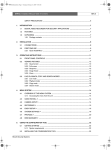
ATM/POS bridge
EN
Installation Manual
ATM/POS bridge | Installation Manual
Bosch Security Systems
ii
ATM/POS bridge | Installation Manual
ATM/POS Bridge
Installation manual
Bosch Security Systems
iii
ATM/POS bridge | Installation Manual
iv
IMPORTANT SAFETY INSTRUCTIONS
1. Read these instructions.
2. Keep these instructions.
3. Heed all warnings.
4. Follow all instructions.
5. Do not use this apparatus near water.
6. Clean only with a dry cloth.
7. Do not block any ventilation openings. Install in accordance with the
manufacturer's instructions.
8. Do not install near any heat sources such as radiators, heat registers,
stoves, or other apparatus (including amplifiers) that produce heat.
9. Do not defeat the safety purpose of the polarized or grounding-type plug.
A polarized plug has two blades with one wider that the other. A groundingtype plug has two blades and a third grounding prong. The wide blade or
third prong are provided for your safety. If the provided plug does not fit into
the outlet, consult an electrician for replacement of the obsolete outlet.
10. Protect the power cord from being walked on or pinched particularly at
plugs, convenience receptacles, and the point where they exit from the
apparatus.
11. Only use attachments/accessories specified by the manufacturer.
12. Use only with the cart, stand, tripod, bracket, or table
specified by the manufacturer, or sold with the apparatus.
When a cart is used, use caution when moving the cart/
apparatus combination to avoid injury from tip-over.
Bosch Security Systems
ATM/POS bridge | Installation Manual
v
13. Unplug this unit during lightning storms or when unused for long periods
of time.
14. Refer all servicing to qualified service personnel. Servicing is required
when the apparatus has been damaged in any way, such as power-supply
cord or plug is damaged, liquid has been spilled or objects have fallen into
the apparatus, the apparatus has been exposed to rain or moistue, does not
operate normally, or has been dropped.
CAUTION
This unit has a battery inside the enclosure. Risk of explosion if battery is
replaced by incorrect type. Dispose of used battery in an environmentally
friendly way. Do not dispose of the battery with other solid waste.
Remark
Bosch has a strong commitment towards the environment. This unit has been
designed to respect the environment as much as possible.
FCC & ICES INFORMATION
(U.S.A. and Canadian Models Only)
This is a Class B product. This device complies with Part 15 of the FCC
rules. Operation is subject to the following two conditions: (1) this device
may not cause harmful interference, and (2) this device must accept any
interference received, including interference that may cause undesired
operation.
CAUTION
Use of controls or adjustments or performance of procedures other than
those specified herein may result in hazardous radiation exposure.
Bosch Security Systems
ATM/POS bridge | Installation Manual
Bosch Security Systems
vi
EN | 1
ATM/POS bridge
Table of Contents
1.
2.
3.
4.
5.
ATM/POS bridge ................................................................................................... 3
1.1 Package contents ...................................................................................... 3
1.2 Supported protocols................................................................................. 3
1.3 Mounting ...................................................................................................... 3
1.4 Applications ................................................................................................ 4
1.5 Connections................................................................................................ 5
Configuration........................................................................................................... 7
2.1 How to set up a HyperTerminal session .............................................. 7
2.2 Configuration menus................................................................................. 8
Connectors........................................................................................................... 11
Troubleshooting................................................................................................... 12
Technical specifications .................................................................................... 13
Bosch Security Systems
English
ATM/POS bridge | Installation Manual
English
ATM/POS bridge | Installation Manual
SAFETY PRECAUTIONS
CAUTION
RISK OF ELECTRIC
SHOCK. DO NOT OPEN!
CAUTION: TO REDUCE THE RISK OF ELECTRICAL
SHOCK, DO NOT OPEN COVERS. NO USER
SERVICEABLE PARTS INSIDE. REFER SERVICING TO
QUALIFIED SERVICE PERSONNEL.
This label may appear on the bottom of the unit due to space limitations.
The lightning flash with an arrowhead symbol within an
equilateral triangle is intended to alert the user to the
presence of uninsulated "dangerous voltage" within the
product's enclosure that may be of sufficient magnitude
to constitute a risk of electric shock to persons.
The exclamation point within an equilateral triangle
is intended to alert the user to presence of important
operating and maintenance (servicing) instructions in
the literature accompanying the appliance.
WARNING
TO REDUCE THE RISK OF FIRE OR ELECTRIC SHOCK, DO
NOT EXPOSE THIS APPARATUS TO RAIN OR MOISTURE
AND OBJECTS WITH LIQUIDS, SUCH AS VASES, SHOULD
NOT BE PLACED ON THIS APPARATUS.
Attention: Installation should be performed by
qualified service personnel only in accordance with the
National Electrical Code or applicable local codes.
Power Disconnect. Units have power supplied
whenever the power cord is inserted into the power
source. The power cord is the main power disconnect
for all units.
The socket outlet shall be installed near the
equipment and shall be easily accessible.
Bosch Security Systems
EN | 2
1.
EN | 3
ATM/POS bridge
The ATM/POS bridge connects a Point-of-Sale (POS) or an Automatic Teller Machine
(ATM) to a Bosch digital video recorder so that transactional data from these units can
be stored and displayed with associated video recordings.
1.1 Package contents
Check the package for following items:
• ATM/POS bridge
• External DC power supply
• Mounting kit
• 2 connection cables and 1 console cable (with two 9-pole SubD connectors)
• Installation manual (this manual)
1.2 Supported protocols
The ATM/POS bridge is designed to operate with many different terminals. If you have
any questions regarding the suitability of the firmware for your terminal or any other
enquiries, contact your Bosch representative.
1.3 Mounting
Using the screws provided, attach the two mounting brackets to the sides of the bridge.
Secure the brackets to a solid fixture.
Bosch Security Systems
English
ATM/POS bridge | Installation Manual
English
ATM/POS bridge | Installation Manual
EN | 4
1.4 Applications
The following illustration shows an example of how a bridge is used in a network of digital
video recoders and POS terminals.
The following illustration shows an example of how a bridge is used in a network of digital
video recoders and ATM terminals.
Bosch Security Systems
EN | 5
1.5 Connections
Using the supplied cables, connect the bridge as follows:
1. Connect the supplied DC power adapter unit to the DC power input connector of
the bridge.
2. Connect the RJ45 connector of the bridge via a straight Ethernet CAT5 network
cable to a network switch or hub that supports 10BaseT. Alternatively, the bridge can
be connected directly to the digital video recorder via a cross-over cable.
3. To configure the bridge, use an RS232 cable to connect the COM3 (console) port to
the serial port of a PC. If you use the RS232 console cable supplied with the bridge,
ensure that the bridge is powered before connecting the cable.
COM 3 (console) RS232 connector
DC Power input connector
Ethernet RJ45 connector
Activity indicator
COM 4 RS485 connector
Bosch Security Systems
COM 2 RS232 connector
COM 1 RS232 connector
English
ATM/POS bridge | Installation Manual
English
ATM/POS bridge | Installation Manual
EN | 6
4. Connect your terminal to COM port 1, 2, 3 or 4 of the bridge using the supplied
cable. Choose the COM 4 port on the bridge if your connection protocol is RS485.
Normally, you would use the supplied splitter cable to make this connection. For
example, you remove the existing cable that connects your terminal to the
printer. Use the supplied splitter cable to connect the terminal to the printer.
The third connector of the splitter cable then connects to the supplied
connection cable which connects to the bridge.
POS terminal
Supplied splitter
cable
Printer
Supplied
connection cable
Digital
Video
Recorder
ATM/POS
bridge
Ethernet
cross-over
cable
To select the communication parameters for the ports and the network parameters, use a
PC to start a configuration session as described below. The activity LED lights when the
bridge is active.
Note
To download firmware to the bridge you must use the supplied RS232 cable connected
to the COM3 (console) port. In this situation the cable must be connected to the bridge
before it is powered.
Bosch Security Systems
2.
EN | 7
Configuration
The ATM/POS bridge is configured via a PC HyperTerminal session. The PC is
connected via a COM serial port to the COM 3 (console) port of the bridge. Start a
HyperTerminal session on the PC to get access to the configuration menu of the bridge.
2.1 How to set up a HyperTerminal session
1. Start the PC HyperTerminal program in Windows (normally available under
Start_Programs_Accessories_Communications).
2. Enter a name for the HyperTerminal session and click OK.
3. For the connection, select the COM port number of the PC.
4. Fill in the following values for the COM port properties and click OK:
Bosch Security Systems
English
ATM/POS bridge | Installation Manual
English
ATM/POS bridge | Installation Manual
EN | 8
5. If the bridge is switched on, a welcome message is shown on the screen. This
message prompts you to press the F1 key (a function key on your keyboard).
6. Press the F1 key; the screen displays the System Options Menu.
7. To configure the bridge, navigate through the menus using the numeric keys on your
keyboard to select menu items.
2.2 Configuration menus
2.2.1 System options menu
The system options menu has 6 items:
1.
2.
3.
4.
5.
6.
Network Setup
Communication Channels
Terminal Setup
Simulation mode
Recording Language
Service Menu
Network Setup
The Network Setup submenu enables you to configure network settings and enter a
bridge name:
1
Bridge Name
BRIDGE-01
2
IP-Address
192.168.10.2
3
Subnet Mask
255.255.255.0
4
Default Gateway
0.0.0.0
5
Recorder TCP Port
4200 (default)
6
Service TCP Port
4201 (default)
The MAC Address of the bridge is shown but cannot be changed.
Bosch Security Systems
EN | 9
Communication Channels
In the Communication Channels submenu you can select one of the four COM ports to
configure. The submenu that appears depends on the setting of the Comport Mode. Enter
the parameters that are required for your terminal.
1
Comport Mode
Asynchronous
3
Baudrate
9600
4
Databits
8 bits
5
Parity
None
6
Stop bits
1bit
7
Flow Control
Off
Terminal Setup
In the Terminal Setup submenu you can select one of the four connected terminals to
configure. Enter a terminal name and select the type of device connected to your
terminal. Contact your local sale representative if your device is not listed in the menu
for selection. Our firmware is continously extended with new options.
1
Name
TERMINAL-01
2
Device
Epson TM-T88III (example)
3
Comm Channel
Com 1 - RS232
4
Address
0
Simulation Mode
The Simulation Mode is used to test the connection between the bridge and the digital
recorder. If this mode is selected, sample data is sent from the bridge to the digital
recorder.
Bosch Security Systems
English
ATM/POS bridge | Installation Manual
English
ATM/POS bridge | Installation Manual
EN | 10
Recording Language
Select the same language that is set on the connected digital recorder. This ensures that
characters are displayed correctly. The configuration menu language continues to be
English.
Service Menu
The Service Menu is used to restore the bridge to factory defaults, to reset the bridge, or
to do diagnostics.
Bosch Security Systems
3.
EN | 11
Connectors
The four COM connectors are all 9-pin SubD-type male connectors.
1
5
6
9
The following table lists the signals and pin numbers for the four ports.
COM 1
RS 232
Pin
COM 3
(console)
RS 232
COM 2
RS 232
COM 4
RS 485
1
2
Rx
Rx
Rx
D2+
3
Tx
Tx
Tx
D2-
GND
GND
GND
GND
7
RxC
RxC
8
TxC
TxC
4
5
6
9
Bosch Security Systems
INIT
English
ATM/POS bridge | Installation Manual
English
ATM/POS bridge | Installation Manual
4.
EN | 12
Troubleshooting
If you are unable to capture transaction data, perform the following steps:
1. Recheck your cables.
2. Check your TCP/IP network connection with the ATM/POS bridge. Check your
gateway and subnet mask settings, they must match the digital recorder settings.
3. If the recorder has established communication with your bridge and you still cannot
capture the transaction data, use the simulation mode of the bridge in the System
Options Menu. The bridge will send sample transactions to the recorder in this
mode.
4. Check the COM ports settings in your bridge. If the transaction data is being
recorded, but shows the wrong characters, check the COM port settings. The
language setting must be the same as the recorder language setting.
5. If your recorder requires an ATM/POS software license (for example, the Divar 2
digital versatile recorder), please check if this license is enabled in the System
Settings - Licenses submenu of the Divar.
Bosch Security Systems
5.
EN | 13
Technical specifications
Electrical
Power supply:
External DC power supply (supplied)
Input: 100-240 VAC; 150mA, 50/60Hz
Output: 12 VDC; 450mA
Connector:
DC jack, positive center pin; 10-30 VDC; 2W
Mechanical
Dimensions:
152 x 110 x 35 mm / 5.98 x 4.33 x 1.38 inch
Weight:
Approx. 0.6 kg / 1.3 lbs
Mounting kit:
Supplied
Interface
Ethernet:
RJ45 shielded, 10 BaseT
Com 1 port:
9-pin SUBD male connector; RS232 synchronous or
asynchronous signals according to EIA/TIA-232-F
Com 2 port:
9-pin SUBD male connector; RS232 synchronous or
asynchronous signals according to EIA/TIA-232-F
Com 3 (console) port:
9-pin SUBD male connector; RS232 asynchronous signals
according to EIA/TIA-232-F
Com 4 port:
9-pin SUBD male connector; RS485 asynchronous
Environmental
Temperature:
Operating: +0°C to +45°C (+32°F to +113°F)
Storage: -25°C to +70°C (-13°F to +158°F)
Relative humidity:
Operating: < 80% non-condensing
Storage: < 90% non-condensing
Bosch Security Systems
English
ATM/POS bridge | Installation Manual
English
ATM/POS bridge | Installation Manual
Electromagnetic Compatibility
EMC requirements:
USA: FCC Part 15, Class B
EU: EMC directive 89/336/EEC
Immunity: EN50130-4
Emission: EN55022 Class B
Harmonics: EN61000-3-2
Voltage fluctuations: EN61000-3-3
Safety:
USA: UL60950
EU: EN60950
Canada: CAN/CSA - C22.2 - 60950-00
Bosch Security Systems
EN | 14
ATM/POS bridge | Installation Manual
Bosch Security Systems
ATM/POS bridge | Installation Manual
Bosch Sicherheitssysteme GmbH
Bosch Security Systems B.V.
Ludwig-Bölkow-Allee
P.O. Box 80002
85521 Ottobrunn
5600 JB Eindhoven
Germany
The Netherlands
www.bosch-sicherheitssysteme.de
www.boschsecuritysystems.com
3122 165 2272.2
© 2004 Bosch Security Systems B.V.
Subject to change. Printed in The Netherlands.
Bosch Security Systems