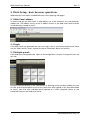
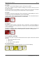
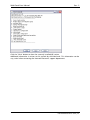
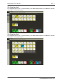
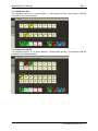
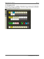
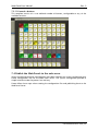
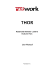
1
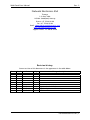
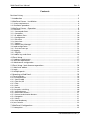
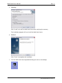
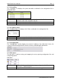
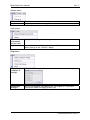
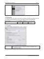
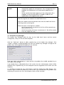
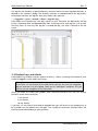
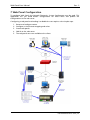
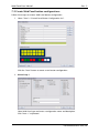
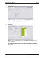
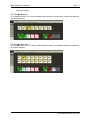
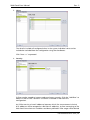
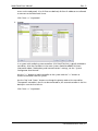
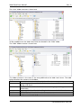
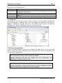
er
VikinX User Manual
Web Panel
network-electronics.com
Rev. 2
Web Panel User Manual
Rev. 2
Network Electronics ASA
Thorøya
P.O. Box 1020
N-3204 Sandefjord, Norway
Phone: +47 33 48 99 99
Fax: +47 33 48 99 98
Email: [email protected]
www.network-electronics.com
Support Phone: +47 90 60 99 99
Revision history
Current revision of this document is the uppermost in the table below.
Rev.
Repl.
Date
Sign
2
1
0
1
0
-
2007-10-11
2007-09-24
2007-09-19
CAA
JGS
JGS
Change description
Updated and clarified text
Updated pictures with new layout
Initial revision
network-electronics.com | 2
Web Panel User Manual
Rev. 2
Contents
Revision history..........................................................................................................2
1 Introduction ...........................................................................................................5
2 Web Panel Server - Installation................................................................................6
2.1 System requirements ..................................................................................................... 6
2.2 Installation procedure .................................................................................................... 6
3 Web Panel Server - Operation.................................................................................9
3.1 Overview ....................................................................................................................... 9
3.1.1 Connected clients ....................................................................................................... 9
3.1.2 Controllers................................................................................................................ 10
3.1.3 IP address filters ........................................................................................................ 10
3.1.4 Configuration ........................................................................................................... 10
3.1.5 File menu ................................................................................................................. 10
3.1.6 Status bar ................................................................................................................. 12
3.1.7 Options .................................................................................................................... 12
3.1.8 Product Key Manager ............................................................................................... 13
3.2 Load configuration ...................................................................................................... 14
3.2.1 First time start-up ..................................................................................................... 14
3.3 Logging....................................................................................................................... 15
3.3.1 Log files.................................................................................................................... 15
3.4 Product keys and clients .............................................................................................. 16
4 Client Setup..........................................................................................................17
4.1 Hardware requirements ............................................................................................... 17
4.2 Software requirements................................................................................................. 17
4.3 Web browser configuration.......................................................................................... 17
5 Client Setup - basic browser operations ................................................................18
5.1 Web Panel address....................................................................................................... 18
5.2 Login........................................................................................................................... 18
5.3 Multiple panels ............................................................................................................ 18
6 Operating a Web Panel.........................................................................................19
6.1 Panel selection............................................................................................................. 19
6.2 Function buttons ......................................................................................................... 19
6.2.1 Panel Enable ............................................................................................................. 19
6.2.2 Take On/Off ............................................................................................................. 19
6.2.3 Take ......................................................................................................................... 20
6.2.4 Lock ......................................................................................................................... 20
6.2.5 Protect ..................................................................................................................... 20
6.3 Crosspoint switching ................................................................................................... 20
6.3.1 Source buttons ......................................................................................................... 20
6.3.2 Destination buttons .................................................................................................. 21
6.3.3 Source-to-destination buttons................................................................................... 21
6.3.4 Categories ................................................................................................................ 21
6.3.5 Salvos ....................................................................................................................... 21
6.3.6 Level breakaway ....................................................................................................... 22
6.4 Java Console ................................................................................................................ 22
7 Web Panel Configuration......................................................................................24
7.1 Prerequisites ................................................................................................................ 25
network-electronics.com | 3
Web Panel User Manual
Rev. 2
7.1.1 Enabling Web Panel configuration ............................................................................ 25
7.1.2 Router System .......................................................................................................... 25
7.1.3 Virtual Router Mapping............................................................................................. 25
7.1.4 Salvos ....................................................................................................................... 25
7.2 Create Web Panel button configurations...................................................................... 26
7.3 Web panel templates ................................................................................................... 28
7.3.1 Single bus 8x1 .......................................................................................................... 29
7.3.2 Single bus 16x1 ........................................................................................................ 29
7.3.3 Dual bus 16x2 .......................................................................................................... 30
7.3.4 Dual bus 32x2 .......................................................................................................... 30
7.3.5 Multi bus 8x8 ........................................................................................................... 31
7.3.6 Multi bus 16x16 ....................................................................................................... 31
7.3.7 Salvo 4 ..................................................................................................................... 32
7.3.8 Salvo 8 ..................................................................................................................... 32
7.3.9 Category 8x8............................................................................................................ 32
7.3.10 Category 16x16...................................................................................................... 33
7.3.11 General x buttons ................................................................................................... 34
7.4 Publish the Web Panels to the web server .................................................................... 34
7.5 Files and folders ........................................................................................................... 39
7.5.1 Local files.................................................................................................................. 39
7.5.2 Web files................................................................................................................... 41
7.6 User customization ...................................................................................................... 41
7.6.1 CSS .......................................................................................................................... 42
7.6.2 Custom Web Panel ................................................................................................... 43
network-electronics.com | 4
Web Panel User Manual
Rev. 2
1 Introduction
The Web Panel Server is an application that connects the clients with the routers
(SYSCON/ETHCON). This application runs on a standard Windows XP computer and uses
Internet Information Services (IIS) as its web hosting service.
A client connects to the Web Panel Server through HTTP and retrieves an HTML page
containing a web panel from Network Electronics. A TCP/IP connection is established
between the client and the Web Panel Server using JAVA for handling user actions and
feedback.
The Web Panel Server also connects to the router system for handling router commands and
status.
The Web Panel Server loads a configuration created by the administrator using the Network
Electronics System Configurator. All the configuration files can be automatically uploaded to
the Web Panel Server by the System Configurator. The configuration files contain web panel
button layouts, virtual router mapping, salvos, IP filter etc.
network-electronics.com | 5
Web Panel User Manual
Rev. 2
2 Web Panel Server - Installation
The Web Panel Server must be installed from a CD delivered by Network Electronics ASA.
2.1 System requirements
In order to run the Web Panel server, please verify these minimum hardware requirements:
−
Pentium IV 2GHz CPU or similar
−
1 GB RAM
−
200 MB free disk space
−
CD/DVD-ROM
−
100/1000 Mb/s NIC
2.2 Installation procedure
Please follow these steps to install the Web Panel Server.
1. Insert the CD-ROM received from Network Electronics ASA when ordering this
product. If the installation doesn’t start automatically, execute the installation file
located on the CD. Select “Install Web Panel Server” to start the installation.
2. Welcome
Click “Next >” to proceed.
network-electronics.com | 6
Web Panel User Manual
Rev. 2
3. License agreement
Select the “I accept the terms in the license agreement” and click “Next >” to
proceed.
4. Destination folder
Verify that the destination folder is correct. Click the “Change…” button if you want
to change the destination folder.
Click “Next >” to proceed.
network-electronics.com | 7
Web Panel User Manual
Rev. 2
5. Summary
Click “Install” to install the Web Panel Server after verifying the summary.
The installation program will now install the Web Panel Server.
6. Finished
Click “Finish” to complete the installation
7. Start the Web Panel Server by double-clicking the icon on the desktop.
network-electronics.com | 8
Web Panel User Manual
Rev. 2
3 Web Panel Server - Operation
The Web Panel Server is a Windows application designed to run without any user interaction.
Once the application is set up and started there is no need for any further user operations.
3.1 Overview
The Web Panel Server displays status tables, configuration info, a file menu and a status bar.
3.1.1 Connected clients
All clients logged in are displayed in the “Connected clients” list. The number of currently
connected clients and the number of maximum allowed clients are both shown on the status
bar.
The columns in the “Connected clients” list can be described as follows:
User
IP address:Port
Active panel
Connected
Displays user- and lock id of the current web panel.
Displays the client’s IP address and port used to connect to the server.
Displays the name of the web panel currently used by the client.
Displays the time and date the client connected.
network-electronics.com | 9
Web Panel User Manual
Rev. 2
3.1.2 Controllers
The “Controllers” list displays the system controllers as defined in the configuration files in
prioritized order.
Priority
Hostname
IP address
Displays the priority of the controller. If a controller fails, the server
connects to the next controller in the list.
Displays the hostname of the controller.
Displays the IP address of the controller.
3.1.3 IP address filters
The “IP address filters” list displays the IP filters as defined in the configuration files.
From
To
The filter accepts client IP addresses from this address, inclusive.
The filter accepts client IP addresses to this address, inclusive.
3.1.4 Configuration
The “Configuration” section displays the current IP address of the Web Panel Server, the
currently selected configuration file and the currently selected log file destination.
3.1.5 File menu
The file menu is used for starting and stopping the server, opening configuration files and
configuring options.
File menu
Open…
Exit
Opens a file browse dialog for locating a configuration file. The default
file name is: “WebConfig.xml”.
Stops the Web Panel Server and shuts down the application.
network-electronics.com | 10
Web Panel User Manual
Rev. 2
Actions menu
Start server
Stop server
Starts the server if it isn’t running.
Stops the server if it is running.
Tools menu
Internet
Information
Services (IIS)
Options…
Opens the IIS configuration dialog.
Opens the “Options” dialog. See chapter 3.1.7 for more information
about settings in the “Options” dialog.
Help menu
Display
computer IP
Settings
Shows a small dialog with the current Web Panel Server IP settings.
Release Log
Product Key
Manager
Opens the release log for the Web Panel Server.
Use this to configure the product keys. See chapter 3.1.8 for more
information about managing product keys.
network-electronics.com | 11
Web Panel User Manual
About
Rev. 2
Displays a dialog with information about version and copyrights.
3.1.6 Status bar
The status bar shows the current server status, the current controller connection status and
the number of connected clients as well as the number of maximum allowed clients.
Current server status.
Controller
connection.
Client
connections.
Reserved for
future use.
3.1.7 Options
The options dialog can be opened from “Tools”->”Options…”.
Network
Select which Network Interface Card (NIC) to be used for communication
with controllers and clients. Displays the currently selected NIC and
corresponding IP address.
network-electronics.com | 12
Web Panel User Manual
Configuration
updates
Select one of the following options:
− Automatically apply new configuration. If the configuration file is
modified, the modifications are automatically applied to the
server.
−
Logging
Rev. 2
Ask for confirmation before applying. If the configuration file is
modified, a manual confirmation is needed in order for the
modifications to be applied to the server.
Use the “Browse” button to select the log file path. Displays the directory
where the log files are stored on the Web Panel Server.
Select the number of minutes between each time the Web Panel Server
writes log entries to the log file.
Select how often a new log file is created:
− New file every hour. A maximum of 24 files will be created every
day (smaller file sizes).
−
New file every day (24 hours). A maximum of 1 file will be created
every day (larger file sizes).
3.1.8 Product Key Manager
The Product Key Manager holds the keys for the Web Panel Server and the System
Configurator, if they run on the same computer.
Click the “Add new” button to add a product key to the Product Key Manager. Click
“Delete” to delete a selected product key from the Product Key Manager. Changes to the
product keys will be applied immediately in the software.
Enter your name, your company’s name and the new product key to add a product key to
the Product Key Manager.
If you already have a valid product key in the system, the user- and company names will be
disabled since all product keys on one computer must be registered to the same user and
company.
It is possible to change the user- and company names by clicking the “Edit” buttons. This,
however, might render other product keys useless and is not recommended! Only product keys
matching the currently set user- and company names will be activated.
network-electronics.com | 13
Web Panel User Manual
Rev. 2
3.2 Load configuration
The configuration files are created by the Network Electronics System Configurator and
published to a local folder on the computer running the Web Panel Server.
All the configuration files are located in the content directory mapped to the virtual directory
as configured in the IIS.
The Web Panel Server must locate the “WebConfig.xml” file created by System Configurator
and open it. This file contains all the Web Panel button layouts, virtual router mapping,
salvos, controller settings, IP filters etc.
Select “File”->”Open…” in the Web Panel Server file menu to browse for the configuration
file. The selection is saved to registry and used next time the Web Panel Server is started.
3.2.1 First time start-up
When the Web Panel Server is started for the first time, the following message appears:
Click “OK” and browse for the configuration file.
This message will only appear as long as there is no valid configuration file to be found when
you start the Web Panel Server.
network-electronics.com | 14
Web Panel User Manual
Rev. 2
3.3 Logging
The Web Panel Server can be configured to log all activities to file. Log options can be
modified in the “Options” dialog, located at “Tools”->”Options”.
Logging can be enabled and disabled using the “Logging” checkbox.
The destination of the log files can be modified by clicking the “Browse” button. All local
and network drives can be used as the log destination, which indicates the directory where
the log files will be stored.
The Web Panel Server collects log entries in an internal buffer and writes the collected entries
to a log file at user defined intervals. Set the log interval as the number of whole minutes
between each time the log file is accessed.
At times with a lot of activity, the update interval should be relatively short to limit the size of
the internal log buffer. On the other hand, when there is little activity, the update interval
may be increased accordingly.
When a log entry is written to file, its timestamp is verified and a new log file is created if
necessary. The maximum number of log files created every day is user defined:
−
Every hour; yields a maximum number of 24 log files per day.
− Every day; yields a maximum number of 1 log file per day.
Depending on how the log files shall be used, these configurations can be changed to fit the
needs for statistics and analysis tools.
In a normal broadcast application one log file every day and log file updates each 10 minute
is suitable.
3.3.1 Log files
The log file is a standard ASCII text file with comma separated values. It can easily be
imported into other applications for statistics and analysis, e.g. Microsoft Excel.
network-electronics.com | 15
Web Panel User Manual
Rev. 2
The log files are stored in a specific directory structure within the main log path directory as
defined in the “Options” dialog. The directory structure is created based on the log entries’
timestamps and sorts the log files after year, month, day and hour:
“..\<log path>\<year>\<month>\<date>\<log file>.log”
New folders are created every new day, month or year. Filenames are defined by the log
entries’ timestamp date and appended the hour if the interval for new log files is set to new
file every hour. In case only one log file is created per day, the time is omitted in the file
name.
3.4 Product keys and clients
Each product key enables a certain amount of clients, “clients” meaning the number of users
currently logged in to the Web Panel Server.
Example:
If you have a 1 user licence for the Web Panels you can use your own computer,
log out and then use your laptop, home pc or a colleague’s computer. But you
cannot use two computers at the same time.
When you order the Web Panel product from Network Electronics ASA you can choose
between several client limitations:
−
1 user licence
−
5 user licence
− 10 user licence
If you buy a 5 user licence and need to upgrade later you will receive a new product key to
be inserted into the product key manager. The number of maximum allowed clients will
then be increased according to your purchase.
network-electronics.com | 16
Web Panel User Manual
Rev. 2
4 Client Setup
Before you start using a web panel on your client computer please read through this section
of prerequisites.
4.1 Hardware requirements
Please verify these minimum hardware requirements:
Operating system
CPU
Memory
Disk space
NIC
Removable device
Windows, Linux and MAC
Pentium IV 2 GHz or similar
1 GB RAM
200 MB
100/1000 Mb/s
CD/DVD-ROM
4.2 Software requirements
Please make sure that these software requirements are met:
Java Runtime
Environment (JRE)
Recommended web
browser
Optional browsers
JRE 6.1 (www.java.com)
Mozilla Firefox (www.firefox.com)
- Opera (www.opera.com)
- Safari (www.apple.com)
- Netscape
- Internet Explorer (limited functionality)
4.3 Web browser configuration
Java must be enabled in your web browser before Web Panels can be used. These settings
may vary from browser to browser.
In the Mozilla Firefox web browser Java settings are located under “Tools”->”Options” and
the "Content" tab.
network-electronics.com | 17
Web Panel User Manual
Rev. 2
5 Client Setup - basic browser operations
Web browsers have certain standard behaviors when opening web pages.
5.1 Web Panel address
To locate and get the Web Panel a valid address has to be entered in the web browser’s
address bar. The address consists of the IP address shown in the Web Panel Server and the
virtual directory created in the IIS.
5.2 Login
If the Web Panels are protected the user must log in with a username and password. Please
see the "Web Panel IIS Setup" manual for further information about user security.
5.3 Multiple panels
Each Web Panel configured to be a part of the configuration is shown in the panel list on the
left side.
Using the tab functionality in the web browser or opening several windows enables the user
to have several control panels active at the same time. With regards to the licensed number
of clients, note that each individual panel opened on a client computer counts as one
connected client on the Web Panel Server.
network-electronics.com | 18
Web Panel User Manual
Rev. 2
6 Operating a Web Panel
6.1 Panel selection
The user can easily switch between the panels by clicking the panel name on the left side of
the web page.
6.2 Function buttons
This section describes the functionality of the standard function buttons.
Every function button described here is optional and can be left out of any button
configuration.
6.2.1 Panel Enable
This button is used to enable or disable a Web Panel (all buttons).
One click on the button changes its state between:
Enabled
Disabled
6.2.2 Take On/Off
This button is used to enable or disable the “Take” button. When the “Take” button is
enabled, all cross point switching must be acknowledged by clicking the “Take” button, for
example when switching a source to a destination or when switching a salvo.
One click on the button changes its state between:
Enabled
Disabled
network-electronics.com | 19
Web Panel User Manual
Rev. 2
6.2.3 Take
This button is used to acknowledge cross point switching when enabled.
When Take is enabled, this button will blink according to level selection when the user tries
to switch the router.
One click on the button acknowledges the currently selected switch command. This button
also has a built in timer turning it off if not clicked within a certain time period.
6.2.4 Lock
This button is used to lock a destination. When a destination is locked nobody can switch it.
The destination must be unlocked before it can be switched again.
To lock or unlock, select a destination and click the lock button. If the selected destination is
already locked, it will be unlocked. Otherwise, it will be locked.
Locked
Unlocked
6.2.5 Protect
This button is used to protect a destination. When a destination is protected nobody can
switch it, except for the user that protected it. The destination must be unprotected before it
can be switched again.
To protect or unprotect, select a destination and click the protect button. If the selected
destination is already protected, it will be unprotected. Otherwise, it will be protected.
Protected
Unprotected
6.3 Crosspoint switching
Switching a cross point using source and destination buttons requires a destination oriented
operation.
1. Select which destination to switch
2. Select source
3. Press take to confirm (optional)
6.3.1 Source buttons
A source button represents a source as defined in the virtual router mapping.
Sources are used in dual- and multi-bus panels.
network-electronics.com | 20
Web Panel User Manual
Rev. 2
6.3.2 Destination buttons
A destination button represents a destination as defined in the virtual router mapping. The
button also displays the current status of the corresponding destination.
The "Breakaway" status indicates that there is a level breakaway on that destination, meaning
that the destination does not match one specific source on all levels.
Destinations are used in dual- and multi-bus panels.
6.3.3 Source-to-destination buttons
A source-to-destination button switches one source to a pre-selected destination.
Source-to-destination buttons are typically used in single bus panels.
6.3.4 Categories
Category buttons are used when there are more sources than source buttons or more
destinations than destination buttons. A category button scrolls through multiple pages of
predefined sources or destinations and changes the contents of the corresponding buttons.
The “VTR” category contains all VTRs.
The “SAT” category contains all satellite feeds (SAT).
Clicking the category select button (indicated by a red ring in the figure above), all the
category display buttons change their content accordingly. Please see the "System
Configurator User Manual" for more information about categories.
6.3.5 Salvos
Salvo buttons (macro, preset) are used when several cross points are switched to perform a
specified and identical task each time. Typical uses can be: setting up monitor walls,
play&record VTRs, transmission setup etc. One click on a salvo button can for example send
512 crosspoints in one command.
network-electronics.com | 21
Web Panel User Manual
Rev. 2
6.3.6 Level breakaway
“Breakaway” is the term used when audio is split from video. Level breakaway can be
controlled using level buttons. Each level button represents one level (video, audio or data).
When a level button is turned on, the corresponding level is included in cross point
commands. Is the level button turned off, the corresponding level is not included in cross
point commands, possibly inducing a level breakaway status.
Please see the "System Configurator User Manual" for more details about virtual router
mapping and levels.
6.4 Java Console
The Java Runtime Environment (JRE) running on the client computer can be used to solve
problems or help the support department discover errors.
In the system tray (next to the clock) is a Java icon. Right-click the icon and select "Open
Console" to open the Java console.
network-electronics.com | 22
Web Panel User Manual
Rev. 2
Click the "Clear" button to show the currently installed JRE version.
Additional information is written to this console by the Web Panel. This information can be
very useful when contacting the Network Electronics support department.
network-electronics.com | 23
Web Panel User Manual
Rev. 2
7 Web Panel Configuration
To configure Web Panels the Network Electronics System Configurator must be used. This
application lets you build button configurations for Web Panels and publish the
configurations to the web server.
Configuring a web panel and making it available for users requires a few simple steps.
1.
2.
3.
4.
5.
Detect and configure routers
Configure a virtual router mapping and salvos
Create web panels
Publish to the web server
The web panels are now available to the clients
network-electronics.com | 24
Web Panel User Manual
Rev. 2
7.1 Prerequisites
Before you start configuring button configurations for web panels in the System
Configurator, there are some tasks that should be done.
For further information about using the System Configurator, please see the “System
Configurator User Manual”.
7.1.1 Enabling Web Panel configuration
If you are currently using the System Configurator you will need to download the latest
version from the Network Electronics ASA web page or install the version received on a CD
when ordering the product. This only applies for System Configurator version 3.2.7 or older
(Web Panels are supported by System Configurator 3.3.0 and later versions).
In the System Configurator, open “Help”->”Product Key Manager” to verify that you have a
valid System Configurator with the Web Panel feature enabled.
If not, add a new product key with the Web Panel feature by clicking the “Add new” button.
You will have received such a product key when receiving the Web Panel Server product.
7.1.2 Router System
Use the System Configurator to detect your system controllers (SYSCON or ETHCON) and
configure them with correct levels and mnemonics. Redundancy and interconnection should
also be configured.
7.1.3 Virtual Router Mapping
The Web Panels are using the virtual router mapping when controlling routers. Create a
virtual router mapping matching your system. Configure names, icons and categories in the
virtual router mapping.
Note!
Web Panels require a virtual router. It is not possible to configure a web panel
without sources or destinations from a virtual router, except for salvos.
7.1.4 Salvos
If you plan to use salvos on the Web Panels the salvos must be created prior to creating the
Web Panel button configurations.
network-electronics.com | 25
Web Panel User Manual
Rev. 2
7.2 Create Web Panel button configurations
Follow these steps to create a Web Panel button configuration:
1. Select “View”->”Control Panel Button Configuration List”.
Click the “New” button to create a new button configuration.
2. Wizard step 1
Select Web Panel type and enter a configuration name and description.
Click “Next >” to proceed.
network-electronics.com | 26
Web Panel User Manual
Rev. 2
3. Wizard step 2
Enable or disable the standard function buttons.
Click “Next >” to proceed.
4. Wizard step 3
Select the sources and destinations to use in the web panel configuration. Click
“Done” to proceed.
Depending of your web panel type this configuration step will vary. Please refer to
the “System Configurator User Manual” for more information about the different
configurations.
network-electronics.com | 27
Web Panel User Manual
Rev. 2
5. Button configuration editor
The Control Panel Button Configuration is opened when the wizard is completed. For
further information about configuring control panels in the System Configurator click
the “Help” button or see the “System Configurator User Manual”.
Click “OK” to complete the configuration.
7.3 Web panel templates
The following Web Panel templates are available and configurable with the Control Button
Configuration Wizard:
−
Single bus 8x1
−
Single bus 16x1
−
Dual bus 16x2
−
Dual bus 32x2
−
Multi bus 8x8
−
Multi bus 16x16
−
Salvo 4
−
Salvo 8
−
Category 8x8
−
Category 16x16
network-electronics.com | 28
Web Panel User Manual
−
Rev. 2
General x buttons
7.3.1 Single bus 8x1
This template consists of 8 source-to-destination buttons, level buttons and the standard set
of function buttons.
7.3.2 Single bus 16x1
This template consists of 16 source-to-destination buttons, level buttons and the standard set
of function buttons.
network-electronics.com | 29
Web Panel User Manual
Rev. 2
7.3.3 Dual bus 16x2
This template consists of 16 source buttons, two destination buttons, level buttons and the
standard set of function buttons.
7.3.4 Dual bus 32x2
This template consists of 32 source buttons, two destination buttons, level buttons and the
standard set of function buttons.
network-electronics.com | 30
Web Panel User Manual
Rev. 2
7.3.5 Multi bus 8x8
This template consists of 8 source buttons, 8 destination buttons, level buttons and the
standard set of function buttons.
7.3.6 Multi bus 16x16
This template consists of 16 source buttons, 16 destination buttons, level buttons and the
standard set of function buttons.
network-electronics.com | 31
Web Panel User Manual
Rev. 2
7.3.7 Salvo 4
This template consists of 4 salvo buttons and the standard set of function buttons.
7.3.8 Salvo 8
This template consists of 8 salvo buttons and the standard set of function buttons.
7.3.9 Category 8x8
This template consists of a category control panel with 8 source and 8 destination buttons, a
source category select button, a destination category select button, level buttons and the
standard set of function buttons.
network-electronics.com | 32
Web Panel User Manual
Rev. 2
7.3.10 Category 16x16
This template consists of a category control panel with 16 source and 16 destination
buttons, a source category select button, a destination category select button, level buttons
and the standard set of function buttons.
network-electronics.com | 33
Web Panel User Manual
Rev. 2
7.3.11 General x buttons
This template consists of a user defined number of buttons, configurable to any of the
available functions.
7.4 Publish the Web Panels to the web server
When the Web Panel button configurations have been created, the System Configurator may
create configuration files for the Web Panel Server. The System Configurator provides a
simple wizard to make the process fast and easy.
Please follow these steps when creating the configuration files and publishing them to the
Web Panel Server:
network-electronics.com | 34
Web Panel User Manual
Rev. 2
1. Select “Tools”->”Create WebPanels Configuration”
Click “Next >>” to proceed.
2. Virtual Router Mapping
Select the virtual router mapping to use from the drop down box. The list of web
panels is updated based on the virtual router mapping selection. Individual Web
Panels can be included or excluded from the configuration using the checkboxes.
Also, the order of which the web panels will appear on the web page can be
modified with the “Up” and “Down” buttons.
Click “Next >>” to proceed.
network-electronics.com | 35
Web Panel User Manual
Rev. 2
3. Salvos
The salvo list includes all configured salvos in the system. Individual salvos can be
included or excluded from the configuration using the checkboxes.
Click “Next >>” to proceed.
4. Security
IP filters can be created to increase web panel access security. Click the “Add filter” to
add an IP filter or click “Remove” to remove a selected IP filter from the
configuration.
An IP filter consists of two IP addresses between which (the two extremes inclusive)
all IP addresses will be accepted as valid client IP addresses. A client connecting to the
Web Panel Server from an IP address outside any defined IP filter range will be denied
network-electronics.com | 36
Web Panel User Manual
Rev. 2
access to the web panels. If no IP filters are defined, all client IP addresses are allowed
to connect to the Web Panel Server.
Click “Next >>” to proceed.
5. System
In a system with multiple system controllers (SYSCON/ETHCON), typically redundant
controllers, all of the controllers in the same system should be added. For more
information about “Redundancy and Interconnection” settings, see the “System
Configurator User Manual”.
Use the “>>” button to add a controller to the system and the “<<” button to
remove a controller from the system.
Use the “Up” and “Down” buttons to change the priority order of the controllers.
The topmost controller is the first to be connected to; the second controller is the first
backup in case the first fails etc.
Click “Next >>” to proceed.
network-electronics.com | 37
Web Panel User Manual
Rev. 2
6. Summary
The summary step shows the contents of the configuration.
Click “Next >>” to continue and create the configuration files.
network-electronics.com | 38
Web Panel User Manual
Rev. 2
7. Finished
The Web Panel configuration files are now created and stored locally on your
computer at the given location. Due to security reasons publishing the created files to
the Web Panel Server must be done manually.
If you want to do customization before publishing, see chapter 7.6.
Click “Browse” if you want to change the directory to which the configuration files
are published. Click the “Publish” button to publish the configuration files to the Web
Panel Server.
If the Web Panel Server is running and is set up to automatically apply configuration
changes, all communication to any controllers and clients is now stopped, the
configuration files are applied and the Web Panel Server is automatically restarted.
Click “Close” to close the wizard.
7.5 Files and folders
When creating a web panel configuration the files are stored locally on the computer
running the System Configurator. These files must be published to the web server in order to
make them available to the clients.
7.5.1 Local files
Local files mean all files created and updated by the System Configurator in its configuration
folders. The configuration files are per default stored in:
“C:\Program Files\Network Electronics ASA\System Configurator\Conf
network-electronics.com | 39
Web Panel User Manual
Rev. 2
The "Conf" folder structure is shown here:
All files needed to run the Web Panel Server are located in the “Web” folder.
The "Web" folder structure is shown here:
This folder structure is the same as the one published to the Web Panel Server. The table
below describes the contents of the folders.
Folder name
Css
Doc
Java
Panels
Pics
Description of contents
Cascading Style Sheet (CSS) file used in the web panel HTML code for setting
design and layout.
Documents included in the Web Panels containing help and support
information.
Java compiled class files for handling the buttons on the Web Panels.
HTML files for all the Web Panels.
Graphic files (*.png, *.jpg) used on the Web Panels.
network-electronics.com | 40
Web Panel User Manual
Rev. 2
Important files are described here:
File name
Description
WebConfig.xml Contains all mnemonics, icons, virtual router mapping, salvos, controller
configuration and IP filters.
HTML page used as an error page in the IIS.
error.htm
HTML page loaded per default when loading the web panels in a web
index.htm
browser.
Icon shown in the web browsers when opening a web panel page.
favicon.ico
7.5.2 Web files
Files located on the web server are the same as the files in the web folder created by the
System Configurator. In addition there is the “Log” folder which contains all the log files, if
logging is enabled by the Web Panel Server. The default log file location can easily be
changed in the “Options” dialog from within the Web Panel Server.
7.6 User customization
There are several possibilities for the user to customize the Web Panels. The CSS file can be
used to change the layout and design and the web panel HTML files can be edited to meet
any special user requirements.
Note!
User customization requires extensive HTML knowledge.
Network Electronics ASA does not support any user customization. All
modifications are done at your own risk.
Note!
All user customization will be overwritten by the System Configurator and the
publish wizard unless the copy process is done manually!
network-electronics.com | 41
Web Panel User Manual
Rev. 2
7.6.1 CSS
Changing the “Network.css” file located in the “CSS” folder is one way to change the design
of the Web Panels.
Example 1 – Changing the background color
Network.css:
body
{
..
background-color: #2E2D27;
..
}
..
yields a panel like this:
Change the "background-color" property to "#005577" and the web panel looks like this:
All the other properties can be configured in the same way to change the layout and design.
network-electronics.com | 42
Web Panel User Manual
Rev. 2
7.6.2 Custom Web Panel
The HTML file for each web panel can also be changed to meet special user requirements.
Example 2 – Adjust button size
Code from SB 16x1 panel, located in the ".\Panels\*.*" folder:
<div class="buttons" style="top: 70px; min-width: 696px;">
<p>Source selection</p>
<applet width="80" height="80" codebase=".........
<param name="id" value="1" />
<param name="fontname" value="Arial" />
<param name="fontstyle" value="Bold" />
<param name="fontsize" value="12" />
</applet>
<applet width="80" height="80" codebase=".........
<param name="id" value="2" />
<param name="fontname" value="Arial" />
<param name="fontstyle" value="Bold" />
<param name="fontsize" value="12" />
</applet>
−
Changing the applet "width" and "height" properties changes the size of the button.
−
Removing an <applet ..> </applet> section removes a button from the web panel.
−
Copying the <applet ..> </applet> section to another part of the web page relocates
the button on the web panel.
Some minor changes in the code may result in this panel:
When changing the HTML code, please be aware of the following:
−
All buttons need a property with name "id" and a value. The value corresponds to the
button number of the button configuration created in the System Configurator.
−
All web panels need the following communication section:
<div style="top: 489px; width: 938px;">
<applet style="width: 100%; height: 20px .........
<param name="panelname" value="SB 16x1"/>
</applet>
</div>
network-electronics.com | 43