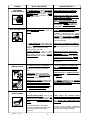
1
GENERAL MANUAL FOR
OIL LUBRICATED
SINGLE STAGE
GASOLINE ENGINE
AIR COMPRESSOR
oduct is not equipped with a spark arr
esting muf
fler
arresting
muffler
fler..
• This prproduct
If the product will be used around flammable
materials, or on land covered with materials such as agricultural crops, forest, brush, grass, or other similar
items, then an approved spark arrester must be installed and is legally required in the state of California. It is a
violation of California statutes section 130050 and/or sections 4442 and 4443 of the California Public Resources
Code, unless the engine is equipped with a spark arrestor, as defined in section 4442, and maintained in effective
working order. Spark arresters are also required on some U. S. Forest service land and may also be legally
required under other statutes and ordinances.
•
Engine exhaust from this product contains chemicals known, in certain quantities, to cause cancer, birth defects or
other reproductive harm.
213 Industrial Dr. • Jackson, TN 38301
MG4-OLENG-2B 5/1/99
TABLE OF CONTENTS
Page
SAFETY GUIDELINES ...................................... 2
Page
OPERATING PROCEDURES ....................... 11
Daily Start-Up Checklist ........................... 11
WARRANTY STATEMENT .............................. 3
WARNING CHART ........................................ 4-5
GLOSSARY ....................................................... 6
DUTY CYCLE .................................................... 6
GENERAL INFORMATION .............................. 6
DESCRIPTION OF OPERATION ..................... 7
ON-RECEIPT INSPECTION ............................ 7
ASSEMBLY INSTRUCTIONS .......................... 8
Items Needed for Assembly ....................... 8
Installing Handle, Foot Extension
Bracket, Wheels, Outlet Valve ..................... 8
INSTALLATION AND BREAK-IN
PROCEDURES ............................................ 9-11
Location of the Air Compressor .................. 9
Permanent Installation ................................. 9
Lubrication, Oil and Gasoline ................. 9-10
Break-in Procedures .............................10-11
MAINTENANCE ....................................... 12-15
Routine Maintenance Schedule ................ 12
Air Compressor ........................................ 13
Compressor Pump Air Intake
Filter - Inspection and Replacement ........ 13
Compressor Oil - Checking and
Changing ................................................... 13
Check Valve - Inspection and
Replacement ............................................. 13
Safety Valve - Inspection and
Replacement ............................................. 13
Engine - Oil Change and Air Cleaner ........ 14
Engine - Adjustments ............................... 14
Belt - Replacement ................................... 15
Pulley and Flywheel - Alignment .............. 15
Storage ..................................................... 15
TROUBLESHOOTING GUIDE .......... 16-17
SERVICE NOTES ............................... 18-19
HOW TO ORDER REPAIR
PARTS ...................................... Back Cover
SAFETY GUIDELINES - DEFINITIONS
This manual contains information that is important for
you to know and understand. This information relates to
protecting YOUR SAFETY and PREVENTING EQUIPMENT PROBLEMS. To help you recognize this information, we use the symbols to the right. Please read the
manual and pay attention to these sections.
DANGER indicates an imminently hazardous situation which, if
not avoided, will result in death or serious injury.
WARNING indicates a potentially hazardous situation which, if
not avoided, could result in death of serious injury.
Call our Toll Free Number 1-800-888-2468, Ext 2,
then 1, to obtain the location of the nearest Authorized
Service Center for ordering repair parts and for warranty
repairs.
CAUTION indicates a potentially hazardous situation which, if
not avoided, may result in minor or moderate injury.
When ordering repair parts from your local Authorized
Service Center, always give the following information:
CAUTION used without the safety alert symbol indicates a
potentially hazardous situation which, if not avoided, may result
in property damage.
• Model number of your compressor
• Part number and description of the
item you wish to purchase
10/2/97
2
LIMITED WARRANTY
ONE YEAR FROM DATE OF PURCHASE
All merchandise manufactured by DeVilbiss Air Power Company/ExCell Manufacturing is warranted to be free of
defects in workmanship and material which occur during the first year from the date of purchase by the original
purchaser (initial user). Products covered under this warranty include: air compressors, *air tools, accessories, service
parts, pressure washers, and generators used in consumer applications (i.e., personal residential household usage
only).
Air compressors, *air tools, accessories, service parts, pressure washers, and generators used in commercial
applications (income producing) are covered by a 90 day warranty.
DeVilbiss Air Power/ExCell Manufacturing will repair or replace, at DeVilbiss/ExCell’s option, products or components
which have failed within the warranty period. Repair or replacement, and service calls on 60 and 80 gallon air
compressors, will be handled by Authorized Warranty Service Centers and will be scheduled and serviced according
to the normal work flow and business hours at the service center location, and depending on the availability of
replacement parts.
All decisions of DeVilbiss Air Power Company/ExCell Manufacturing with regard to this policy shall be final.
This warranty gives you specific legal rights, and you may also have other rights which vary from state to state.
RESPONSIBILITY OF ORIGINAL PURCHASER (Initial User):
o
o
o
o
o
Retain original cash register sales receipt as proof of purchase for warranty work.
Use reasonable care in the operation and maintenance of the product as described in the Owners Manual(s).
Deliver or ship the product to the nearest DeVilbiss Air Power/ExCell Manufacturing Authorized Warranty
Service Center. Freight costs, if any, must be paid by the purchaser.
Air compressors with 60 and 80 gallon tanks only will be inspected at the site of installation. Contact the
nearest Authorized Warranty Service Center, that provides on-site service calls, for service call arrangement.
If the purchaser does not receive satisfactory results from the Authorized Warranty Service Center, the purchaser
should contact DeVilbiss Air Power Company/ExCell Manufacturing.
THIS WARRANTY DOES NOT COVER:
o
o
o
o
o
o
o
o
o
Merchandise sold as reconditioned, floor models and/or display models. Any damaged or incomplete equipment
sold "as is".
Merchandise used as "rental" equipment.
Merchandise that has become inoperative because of ordinary wear, misuse, freeze damage, use of improper
chemicals, negligence, accident, improper and/or unauthorized repair or alterations including failure to operate
the product in accordance with the instructions provided in the Owners Manual (s) supplied with the product.
*Air Tools: O-Rings and driver blades are considered ordinary wear parts, therefore, they are warranted for a
period of 45 days from the date of purchase.
An air compressor that pumps air more than 50% during a one hour period is considered misuse because
the air compressor is undersized for the required air demand. Maximum compressor pumping time per hour is
30 minutes.
Merchandise sold by DeVilbiss Air Power/ExCell Manufacturing which has been manufactured by and identified
as the product of another company. The product manufacturer's warranty will apply.
Repair and transportation costs of merchandise determined not to be defective.
Cost associated with assembly, required oil, adjustments or other installation and start-up cost.
ANY INCIDENTAL, INDIRECT OR CONSEQUENTIAL LOSS, DAMAGE, OR EXPENSE THAT MAY RESULT
FROM ANY DEFECT, FAILURE OR MALFUNCTION OF THE PRODUCT. Some states do not allow the
exclusion or limitation of incidental or consequential damages, so the above limitation or exclusion may not apply
to you.
IMPLIED WARRANTIES, INCLUDING THOSE OF MERCHANTABILITY AND FITNESS FOR A PARTICULAR PURPOSE, ARE LIMITED TO ONE YEAR FROM THE DATE OF ORIGINAL PURCHASE. Some states
do not allow limitations on how long an implied warranty lasts, so the above limitations may not apply to you.
Form: SP-100-F - 10/28/97
213 Industrial Drive • Jackson, TN 38301-9615
Telephone: 1-800-888-2468 , Ext. 2
FAX: 1-800-888-9036
3
IMPORTANT SAFETY INSTRUCTIONS
• SAVE THESE INSTRUCTIONS •
IMPROPER OPERATION OR MAINTENANCE OF THIS PRODUCT COULD RESULT
IN SERIOUS INJURY AND PROPERTY DAMAGE. READ AND UNDERSTAND ALL
WARNINGS AND OPERATING INSTRUCTIONS BEFORE USING THIS EQUIPMENT.
HAZARD
RISK OF
EXPLOSION OR FIRE
WHAT CAN HAPPEN
HOW TO PREVENT IT
GASOLINE AND GASOLINE VAPORS CAN
BECOME IGNITED BY COMING INTO CONTACT WITH HOT COMPONENTS SUCH AS THE
MUFFLER, FROM ENGINE EXHAUST GASES,
OR FROM AN ELECTRICAL SPARK.
TURN ENGINE OFF AND ALLOW IT TO
COOL BEFORE ADDING FUEL TO THE
TANK. EQUIP AREA OF OPERATION WITH A
FIRE EXTINGUISHER CERTIFIED TO HANDLE
GASOLINE OR FUEL FIRES.
COMBUSTIBLE MATERIALS WHICH COME
INTO CONTACT WITH HOT ENGINE PARTS
CAN BECOME IGNITED.
ADD FUEL OUTDOORS OR IN A WELL
VENTILATED AREA. MAKE SURE THERE ARE
NO SOURCES OF IGNITION, SUCH AS
CIGARETTES NEAR REFUELING LOCATION.
OPERATE COMPRESSOR IN AN OPEN AREA
AWAY FROM DRY BRUSH, WEEDS OR
OTHER COMBUSTIBLE MATERIALS.
STORE FUEL IN A SECURE LOCATION AWAY
FROM COMPRESSOR.
UNATTENDED OPERATION OF THIS PRODUCT COULD RESULT IN PERSONAL INJURY
OR PROPERTY DAMAGE.
RISK OF BURSTING
ALWAYS REMAIN IN ATTENDANCE WITH
THE PRODUCT WHEN IT IS OPERATING.
AIR TANK
THE FOLLOWING CONDITIONS COULD
LEAD TO A WEAKENING OF THE TANK, AND
RESULT IN A VIOLENT TANK EXPLOSION:
1. FAILURE TO PROPERLY DRAIN
CONDENSED WATER FROM THE TANK,
CAUSING RUST AND THINNING OF THE
STEEL TANK.
DRAIN TANK DAILY OR AFTER EACH USE.
IF TANK DEVELOPS A LEAK, REPLACE IT
IMMEDIATELY WITH A NEW TANK OR NEW
COMPRESSOR OUTFIT.
2. MODIFICATIONS OR ATTEMPTED
REPAIRS TO THE TANK.
NEVER DRILL INTO, WELD, OR MAKE ANY
MODIFICATIONS TO THE TANK OR ITS
ATTACHMENTS.
3. UNAUTHORIZED MODIFICATIONS TO
THE UNLOADER VALVE, SAFETY
VALVE, OR ANY OTHER COMPONENTS
WHICH CONTROL TANK PRESSURE.
THE TANK IS DESIGNED TO WITHSTAND
SPECIFIC OPERATING PRESSURES. NEVER
MAKE ADJUSTMENTS OR PARTS SUBSTITUTIONS TO ALTER THE FACTORY SET
OPERATING PRESSURES.
4. EXCESSIVE VIBRATION CAN WEAKEN
THE AIR TANK AND CAUSE RUPTURE OR
EXPLOSION. EXCESSIVE VIBRATION
WILL OCCUR IF THE COMPRESSOR IS
NOT PROPERLY MOUNTED OR IF THE
ENGINE OPERATES ABOVE RECOMMENDED RPM.
DO NOT REMOVE THE STIFFENER BAR
CONNECTING THE COMPRESSOR PUMP TO
THE ENGINE, EXCEPT TO ADJUST BELT
TENSION, THEN SECURELY TIGHTEN THE
STIFFNER BAR NUTS. THIS BAR CONTROLS OUTFIT VIBRATION.
ATTACHMENTS & ACCESSORIES
EXCEEDING THE PRESSURE RATING OF AIR
TOOLS, SPRAY GUNS, AIR OPERATED
ACCESSORIES,
TIRES
AND
OTHER
INFLATABLES CAN CAUSE THEM TO EXPLODE OR FLY APART, AND COULD RESULT
IN SERIOUS INJURY.
4
FOR ESSENTIAL CONTROL OF AIR PRESSURE, YOU MUST INSTALL A PRESSURE
REGULATOR AND PRESSURE GAUGE TO
THE
AIR
OUTLET
OF
YOUR
COMPRESSOR.FOLLOW THE EQUIPMENT
MANUFACTURERS RECOMMENDATION AND
NEVER EXCEED THE MAXIMUM ALLOWABLE
PRESSURE RATING OF ATTACHMENTS.
NEVER USE COMPRESSOR TO INFLATE
SMALL LOW-PRESSURE OBJECTS SUCH
AS CHILDREN’S TOYS, FOOTBALLS,
BASKETBALLS. ETC.
HAZARD
WHAT CAN HAPPEN
RISK FROM
FLYING OBJECTS
THE COMPRESSED AIR STREAM CAN CAUSE
SOFT TISSUE DAMAGE TO EXPOSED SKIN
AND CAN PROPEL DIRT, CHIPS, LOOSE
PARTICLES AND SMALL OBJECTS AT HIGH
SPEED, RESULTING IN PROPERTY DAMAGE
OR PERSONAL INJURY.
HOW TO PREVENT IT
ALWAYS WEAR ANSI Z87.1 APPROVED
SAFETY GLASSES WITH SIDE SHIELDS
WHEN USING THE COMPRESSOR.
NEVER POINT ANY NOZZLE OR SPRAYER
TOWARD ANY PART OF THE BODY OR AT
OTHER PEOPLE OR ANIMALS.
ALWAYS TURN THE COMPRESSOR OFF
AND BLEED PRESSURE FROM THE AIR
HOSE AND TANK BEFORE ATTEMPTING
MAINTENANCE, ATTACHING TOOLS OR
ACCESSORIES.
RISK TO BREATHING BREATHING EXHAUST FUMES FROM
ENGINE WILL CAUSE SERIOUS INJURY OR
DEATH.
RISK FROM
MOVING PARTS
ALWAYS OPERATE AIR COMPRESSOR IN A
CLEAN, WELL VENTILATED AREA. AVOID
ENCLOSED AREAS SUCH AS GARAGES,
BASEMENTS, STORAGE SHEDS, ETC., WHICH
LACK A STEADY EXCHANGE OF AIR. NEVER
OPERATE UNIT IN ENCLOSED LOCATIONS
OCCUPIED BY HUMANS OR ANIMALS. KEEP
CHILDREN, PETS AND OTHERS AWAY FROM
AREA OF OPERATION.
THE COMPRESSED AIR FROM YOUR COMPRESSOR IS NOT SAFE FOR BREATHING!
THE AIR STREAM MAY CONTAIN CARBON
MONOXIDE, TOXIC VAPORS OR SOLID
PARTICLES FROM THE TANK.
NEVER INHALE AIR FROM THE COMPRESSOR EITHER DIRECTLY OR FROM A BREATHING DEVICE CONNECTED TO THE COMPRESSOR.
SPRAYED MATERIALS SUCH AS PAINT,
PAINT SOLVENTS, PAINT REMOVER, INSECTICIDES, WEED KILLERS, ETC.. CONTAIN
HARMFUL VAPORS AND POISONS.
WORK IN AN AREA WITH GOOD CROSSVENTILATION. READ AND FOLLOW THE
SAFETY INSTRUCTIONS PROVIDE ON THE
LABEL OR SAFETY DATA SHEETS FOR THE
MATERIAL YOU ARE SPRAYING. USE A
NIOSH/MSHA APPROVED RESPIRATOR
DESIGNED FOR USE WITH YOUR SPECIFIC
APPLICATION.
THE ENGINE CAN START ACCIDENTALLY IF
THE FLYWHEEL IS TURNED BY HAND OR
MOVED BY PULLING ON THE STARTER
ROPE.
ALWAYS DISCONNECT THE SPARK PLUG
AND BLEED PRESSURE FROM THE TANK
BEFORE PERFORMING MAINTENANCE.
MOVING PARTS SUCH AS THE PULLEY,
FLYWHEEL AND BELT CAN CAUSE SERIOUS INJURY IF THEY COME INTO CONTACT
WITH YOU OR YOUR CLOTHING.
NEVER OPERATE THE COMPRESSOR WITH
GUARDS OR COVERS WHICH ARE DAMAGED
OR REMOVED.
ATTEMPTING TO OPERATE COMPRESSOR
WITH DAMAGED OR MISSING PARTS OR
ATTEMPTING TO REPAIR COMPRESSOR
WITH PROTECTIVE SHROUDS REMOVED
CAN EXPOSE YOU TO MOVING PARTS AND
CAN RESULT IN SERIOUS INJURY.
ANY REPAIRS REQUIRED ON THIS PRODUCT
SHOULD BE PERFORMED BY AUTHORIZED
SERVICE CENTER PERSONNEL.
TOUCHING EXPOSED METAL SUCH AS THE
COMPRESSOR HEAD OR OUTLET TUBES OR
CONTACT WITH HOT ENGINE PARTS SUCH
AS THE MUFFLER CAN RESULT IN SERIOUS
BURNS.
NEVER TOUCH ANY EXPOSED METAL
PARTS ON ENGINE OR COMPRESSOR
DURING OR IMMEDIATELY AFTER OPERATION. ENGINE AND COMPRESSOR WILL
REMAIN HOT FOR SEVERAL MINUTES AFTER
OPERATION.
THE GASOLINE ENGINE , THE ENGINE
MUFFLER, THE COMPRESSOR HEAD AND
TUBING BECOME VERY HOT DURING
OPERATION.
DO NOT REACH AROUND PROTECTIVE
SHROUDS OR ATTEMPT MAINTENANCE UNTIL
UNIT HAS BEEN ALLOWED TO COOL.
RISK OF BURNS
GCOLTM — 7/23/97
5
GLOSSARY
SCFM: Standard cubic feet per minute; a unit of
measure of air delivery.
PSIG: Pounds per square inch gauge; a unit of measure
of pressure.
ASME: American Society of Mechanical Engineers;
made, tested, inspected and registered to meet the
standards of the ASME.
CFM: Cubic feet per minute.
California Code: Unit may comply with California Code
462 (L) (2)/(M) (2). Specification/model label is on the
side of the tank on units that comply with California
Code.
Unloader Blow-Off Pressure: All models are continuously running outfits controlled by tank pressure. When
the maximum tank pressure is obtained, the unloader
valve will blow-off. This will cause the compressor to
exhaust the air to the atmosphere and not the tank. This
decreases the load on the engine and allows it to run at
a near no-load condition.
Unloader Reset Pressure: When the tank pressure
drops to a pre-determined point, the unloader valve
closes. The tank pressure will now increase until it
reaches the unloader blow-off pressure.
DUTY CYCLE
All DeVilbiss Air Power manufactured air compressors should be operated on not more than a 50% duty cycle. This
means an air compressor that pumps more than 50% of one hour, is considered misuse, because the air compressor
is undersized for the required air demand. Maximum compressor pumping time per hour is 30 minutes.
GENERAL INFORMATION
You have purchased an air compressor unit consisting
of a 2 cylinder, single-stage air compressor pump, an
air tank, wheels, handle, associated controls and instruments. You may also find an air chuck.
Your air compressor can be used for operating paint
spray guns, air tools, caulking guns, grease guns, air
brushes, sandblasters, inflating tires and plastic toys,
6
spraying weed killers, insecticides, etc. An air pressure
regulator is recommended for most of these applications.
Separate air transformers which combine the functions
of air regulation and/or moisture and dirt removal should
be used where applicable.
DESCRIPTION OF OPERATION
Air Compressor Pump: To compress air, the piston
moves up and down in the cylinder. On the downstroke, air is drawn in through the air intake valves. The
exhaust valve remains closed. On the upstroke of the
piston, air is compressed. The intake valves close and
compressed air is forced out through the exhaust
valve, through the outlet tube, through the check valve
and into the air tank. Working air is not available until
the compressor has raised the air tank pressure above
that required at the air outlet.
the reserve air pressure in the tank. On outfits with no
pressure regulator, this is also the pressure available
at the air outlet.
Throttle Control: A throttle control has been incorporated as an extra feature. When maximum tank pressure is reached and the unloader valve unloads air, it
also activates a throttle control on the engine. This gas
saving feature holds the engine at a factory-set idling
speed until air pressure in the air tank drops to reset
pressure; it then reactivates the throttle control and
accelerates the engine to full throttle.
Check Valve: When the air compressor is operating,
the check valve is "open", allowing compressed air to
enter the air tank. When the air compressor reaches
"cut-out" pressure, the check valve "closes", allowing
air pressure to remain inside the air tank.
Air Intake Filter: This filter is designed to clean air
coming into the pump. This filter must always be clean
and ventilation openings free from obstructions. See
"Maintenance".
Tank Pressure Gauge: The pressure gauge indicates
Unloader Valve: All models are continuously running
outfits controlled by tank pressure. When the maximum tank pressure is obtained, the unloader valve will
exhaust the compressed air to the atmosphere (blowoff). When the tank pressure drops to a pre-determined
point, the unloader valve closes and causes the tank
pressure to increase.
Safety Valve: If the unloader valve does not release
pressure when tank reaches "blow-off" pressure, the
safety valve will protect against high pressure by
"popping off" at its factory set pressure (slightly higher
than the pressure switch cut-out setting).
Shut-off Valve: Turn the knob counterclockwise to
open the valve and clockwise to close.
ON-RECEIPT INSPECTION
Each air compressor outfit is carefully tested and
checked before shipment. With improper handling,
damage may result in transit and cause problems in
compressor operation.
Immediately upon arrival, check equipment for both
concealed and visible damages to avoid expenses
being incurred to correct such problems. This should be
done regardless of any visible signs of damage to the
shipping container. If this product was shipped directly
to you, report any damages to carrier and arrange for
inspection of goods immediately.
For the location or a listing of the nearest DeVilbiss Air
Power Authorized Warranty Service Center, call our toll
free number at 1-800-888-2468, Ext. 2, and talk with
one of our Service Representatives.
7
ASSEMBLY INSTRUCTIONS
Items Needed for Assembly
•
20 oz. of oil for the engine (see Briggs & Stratton
instructions). Use 10W30 high quality motor oil.
•
16 oz. of compressor oil, SAE 20-20W, non-detergent, low foaming.
•
a 9/16" socket or open-end wrench for attaching the
wheels.
•
a 7/16" open-end wrench for attaching the foot
extension bracket and rubber feet.
•
a 1/4" open-end wrench to tighten handle set
screw.
•
an adjustable wrench for attaching the shut-off
valve and air outlet adapter.
Installing Handle, Foot Extension
Bracket, Wheels, Outlet Valve
THE WHEELS AND HANDLE DO NOT PROVIDE ADEQUATE CLEARANCE, STABILITY
OR SUPPORT FOR PULLING THE UNIT UP
AND DOWN STAIRS OR STEPS. THE UNIT
MUST BE LIFTED OR PUSHED UP A RAMP.
EXCESSIVE TANK VIBRATION CAN WEAKEN THE AIR TANK AND CAUSE RUPTURE
OR EXPLOSION. RUBBER FEET MUST BE
INSTALLED.
2. Attach the rubber feet to the bottom of the foot
extension bracket. Attach foot extension bracket to
the air tank bracket. Use one cap screw, one lock
washer, and one hex nut at each end. Tighten.
3. The leg bracket on the underside of the air compressor tank has 2 holes on each side for mounting
the wheels. Place one shoulder bolt through the
hole in a wheel. Next, push the bolt through the
LOWER hole of the leg bracket and screw on one
hex locking nut. The special locking nut does not
turn freely. Tighten the nut firmly until it contacts the
tank leg. See separate Parts Manual. The outfit will
sit level if the wheels are properly installed.
4. Apply teflon tape to the tapered pipe threads on the
adapter and tighten into the manifold. Install the
swivel connection end of the shut-off valve to the
straight threaded end of the adapter (teflon tape is
not required) and tighten this connection. See photo
below.
Do not use the engine gas tank as a support
for lifting the air compressor.
1. Insert the handle into pockets under the tank
saddle. Put one set screw through hole in one side
of tank saddle and tighten down on handle.
ADAPTER
MANIFOLD
SWIVEL
SHUT-OFF CONNECTION
VALVE
It may be necessary to brace or support one
end of the outfit when attaching the wheels
and the foot extension bracket because the
air compressor will have a tendency to tip
before both wheels are assembled.
5. Attach the spark plug wire to the spark plug.
8
INSTALLATION AND BREAK-IN PROCEDURES
Location of the Air Compressor
ENGINE EXHAUST CONTAINS CARBON
MONOXIDE WHICH IS ODORLESS AND
TOXIC. OPERATE ENGINE IN WELL VENTILATED AREAS ONLY.
Operate the air compressor in a clean, dry and well
ventilated area. The air intake filter must be kept clear
of obstructions that could interfere with the flow of air
through the fan bladed flywheel. The air compressor
crankcase and head are designed with fins to provide
proper cooling.
If humidity is high, an air filter can be installed on the air
outlet adapter to remove excessive moisture. Closely
follow the instructions packaged with the filter for proper
installation.
Figure 1
Lubrication, Oil and Gasoline
Multi-Viscosity motor oil, like 10 W30, should
not be used in an air compressor. They leave
carbon deposits on critical components,
thus reducing performance and compressor
life. Use air compressor oil only.
Permanent Installation
BOLTING LEGS TO A STIFF SURFACE CAN
CAUSE TANK RUPTURE RESULTING IN
SERIOUS INJURY OR DAMAGE. DO NOT
PERMANENTLY MOUNT COMPRESSOR TO
ANY SURFACE WITHOUT USING THE VIBRATION MOUNT KIT.
Compressors are shipped without oil. A
small amount of oil may be present in the
pump upon receipt of the air compressor .
This is due to plant testing and does not
mean that the pump contains oil. Do not
attempt to operate this air compressor without first adding oil to the crankcase. Serious
damage can result from even limited operation unless filled with oil and broken in
correctly. Make sure to closely follow initial
start-up procedures.
This compressor may be permanently mounted in one
location such as a truck bed, if desired. A vibration
mount kit is included for this purpose. It is not included
on wheel barrow type units.
1. In order to maintain adequate ventilation for compressor cooling and to avoid contact with pick-up
truck bed, always mount the outfit at least 8" from
any vertical wall. Using the holes in the air tank legs
as a guide, mark and drill four 5/16" diameter holes
in the mounting surface.
2. Insert the vibration mounts in the mounting holes.
Place a flat washer under the mounting surface and
secure each mount with a lock washer and nut. See
Figure 1.
Place unit on a level surface. Remove oil fill plug and
slowly add a compressor oil or Castrol Heavy Duty 30
weight until it is even with the top of the oil fill hole. (It
must not be allowed to be lower than 3/8" -- 6 threads
down -- from the top at any time.) When filling the
crankcase, the oil flows very slowly. If the oil is added
too quickly, it will overflow and appear to be full.
Crankcase oil capacity is 16 fluid ounces.
3. Set the outfit on the exposed threaded ends of the
mounts and secure each mount to the air tank legs
with a lock washer and nut.
NOTE
Drain and refill the compressor pump crankcase after the first 100 hours of operation.
9
INSTALLATION AND BREAK-IN PROCEDURES
For your convenience, purchase a 1/4" NPT nipple,
2 1/2" long, and a 1/4" NPT x 1/4" NPT coupling (pipe
collar) to allow ease in draining oil. Remove oil drain plug
on the gas tank side of the engine and install the nipple.
Thread the coupling on the end of the nipple and screw
the drain plug in the coupling. See Figure 2.
OPEN
POSITION
TOGGLE
LEVER
CLOSED
POSITION
UNLOADER
VALVE
COUPLING
DRAIN
PLUG
NIPPLE
Figure 2
Figure 3
With the unit in a level position, fill the gas tank (approx.
3/4 gal.) with fresh, clean unleaded gasoline. Regular
gas is an acceptable substitute. Do not use premium
gasoline.
GASOLINE VAPOR IS HIGHLY FLAMMABLE. REFUEL OUTDOORS PREFERABLY, OR ONLY IN WELL VENTILATED AREAS. DO NOT REFUEL OR CHECK GASOLINE LEVEL WHILE THE ENGINE IS RUNNING. DO NOT STORE, SPILL OR USE
GASOLINE NEAR AN OPEN FLAME.
Figure 4
NOTE
A warm engine requires less choking than a
cold engine.
DO NOT MIX OIL WITH GASOLINE.
Break-in Procedures
1. Open outlet valve to prevent pressure from building up in the tank. Set toggle lever of unloader valve
in the vertical position to relieve compressor head
pressure. See Figure 3. Move the choke lever to
"choke" position and move on-off lever to the "on"
position. See Figure 4. Pull choke all the way out.
Move stop switch away from spark plug.
10
Unit is top heavy. Make sure the compressor is stable and will not tip before pulling
the starting cord.
INSTALLATION AND BREAK-IN PROCEDURES
2. Place your left hand on the air compressor handle,
and your right hand on the starter handle, and pull
cord out quickly to overcome engine compression
and prevent "kickback". If engine does not start,
push the choke about three-quarters of the way in
or choke lever three quarters to the left and pull
starter handle again. When engine starts, push
choke in or choke lever to the left gradually.
3. Pump Break-in: Open the outlet valve to prevent
tank pressure build-up. Run the air compressor for
30 minutes to seat the rings and lubricate all internal
surfaces. This operation must be completed only
once when first putting the unit in service.
4. After completing the above, and when ready to
begin using the compressor, move the unloader
valve toggle lever to a horizontal position. Close the
outlet valve to build tank pressure.
5. Engine Break-in: After the 1st 5 hours of normal
running, change the engine oil. Then after every 25
hours the engine oil should be changed.
Serious damage may result if the following
break-in instructions are not followed.
OPERATING PROCEDURES
Daily Start-Up Checklist
Perform the following checks before starting the compressor outfit.
1. Make sure that nothing is blocking the belt guard air
openings or air filter opening.
2. Pull the ring on all safety valves to make sure the
valves move freely and smoothly.
3. Check the oil level in the pump as well as the
engine. Add oil if necessary.
4. Clean or blow off fins or any part of compressor that
collects dust and dirt. Compressor will run cooler
and provide longer service.
Start the compressor outfit and check the following:
1. Before attaching an air hose or accessory, make
sure the engine is off. Close the outlet valve or
pressure regulator. (If an optional air pressure
regulator is not used, do not use accessories
rated at less than 110 psig.)
Compressed air from the outfit may contain
water condensation and oil mist. Do not
spray unfiltered air at an item that could be
damaged by moisture. Some air operated
tools or devices may require filtered air.
Read the instructions for the air tool or
device.
When you are finished:
5. Turn off engine.
6. Shut off outlet valve or air pressure regulator.
7. Remove air tool or accessory.
8. Open outlet valve or regulator and allow air to
slowly bleed from the tank. Close the outlet valve
or regulator when the tank pressure is approximately 20 psig.
DRAIN TANK DAILY. WATER WILL CONDENSE IN TANK. IF NOT DRAINED, WATER
WILL CORRODE AND WEAKEN THE AIR
TANK CAUSING A RISK OF TANK RUPTURE. SEE STEP 9.
2. Attach hose and accessory.
TOO MUCH AIR PRESSURE CAUSES A
HAZARDOUS RISK OF BURSTING. CAREFULLY FOLLOW STEPS 3 THROUGH 10
EACH TIME THE COMPRESSOR IS USED.
9. With tank pressure at approximately 20 PSI, open
the drain cock and allow moisture to drain. Turn the
drain T-handle counterclockwise to open.
3. Check the manufacturer's maximum pressure rating for air tools and accessories. The compressor
outlet pressure must never exceed the maximum pressure rating.
If drain cock is clogged, release all air pressure.
The drain cock can then be removed, cleaned,
and then reinstalled.
4. Start the engine and allow tank pressure to build.
Your outfit is ready for use.
10. After the water has been drained, close the drain
cock. The compressor outfit can now be stored.
NOTE
11
MAINTENANCE
DURING MAINTENANCE, YOU COULD BE EXPOSED TO COMPRESSED AIR OR MOVING PARTS.
PERSONAL INJURIES CAN OCCUR. BEFORE DOING ANY MAINTENANCE OR REPAIR, DISCONNECT
THE SPARK PLUG WIRE TO PREVENT ACCIDENTAL STARTING, AND RELIEVE AIR TANK PRESSURE.
NEVER OPERATE THE COMPRESSOR WITH THE BELT GUARD REMOVED.
To ensure efficient operation and longer life of the air compressor outfit, a routine maintenance schedule should be
prepared and followed. The following routine maintenance schedule is geared to an outfit in a normal working
environment operating on a daily basis. If necessary, the schedule should be modified to suit the conditions under which
your compressor is used. The modifications will depend upon the hours of operation and the working environment.
Compressor outfits in an extremely dirty and/or hostile environment will require a greater frequency of all maintenance
checks. Lubricate compressor motor (if required) according to manufacturer's instructions, which are attached to your
Engine Owners Manual.
Routine Maintenance Schedule
Daily:
Every 100 Hours of Operation:
1. Check oil level. Add if necessary.
1. Drain and refill compressor crankcase with 16 fluid
ounces (473.2 ml) of clean compressor oil or Castrol
Heavy Duty 30 weight.
2. Drain water from the air tank, any moisture separators or transformers.
2. Increase frequency of oil changes if humidity or
operating conditions are extreme.
3. Check for any unusual noise and/or vibration.
4. Manually check all safety valves to make sure they
are operating properly.
5. Inspect for oil leaks and repair any leaks found.
Every 160 Hours of Operation:
6. Inspect air filter, replace if necessary.
1. Check drive belt tension; adjust if necessary.
(Refer to SERVICE INSTRUCTIONS in this manual.)
Every 40 Hours of Operation:
2. Inspect air lines and fittings for leaks; correct as
necessary.
1. Clean and inspect the air intake filter; replace if
necessary.
2. Inspect condition of drive belt; replace if necessary.
3. Check the alignment of the motor pulley to the
flywheel. If necessary, align to within 1/32 inch on
centerline.
Each Year of Operation or if a Problem is Suspected:
Check condition of air compressor pump intake and
exhaust valves. Replace if damaged or worn out.
12
MAINTENANCE
Air Compressor
A clean air compressor and engine run cooler and
provide longer service. Clean or blow off fins and any
other parts of the air compressor and engine that collect
dust or dirt. Do not place tags, containers or other
material on or against the ventilation openings in the belt
guard. Adequate ventilation is necessary to maintain
proper air compressor operating temperature.
Check Valve - Inspection and
Replacement
Remove the check valve for inspection or replacement
if air is leaking constantly back through the check valve.
Use the following procedure to inspect, clean or replace
the check valve.
1. Release air pressure from the air tank.
2. Loosen the top and bottom tube nuts and remove
the outlet tube.
Compressor Pump Air Intake
Filter -Inspection and
Replacement
NOTE
Keep the air filter clean at all times. Do not
operate the compressor with the air filter removed.
A dirty air filter will not allow the compressor to operate
at full capacity. Before you use the compressor, check
the air filter to be sure it is clean and in place.
If it is dirty, replace with a new filter. The filter may be
removed by using a pair of needle nose pliers or a
screwdriver. Pull or pry out the old filter and push in a
new one.
3. Unscrew the check valve (turn counterclockwise)
using a socket wrench.
4. Check that the valve disc moves freely inside the
check valve and that the spring holds the disc in
the upper, closed position. The check valve may
be cleaned with a solvent.
5. Apply teflon tape to the check valve threads.
Reinstall the check valve (turn clockwise). The disc
should still move freely - do not over tighten.
6. Replace the outlet tube and tighten top and bottom
nuts.
Safety Valve - Inspection and
Replacement
IF THE SAFETY VALVE DOES NOT WORK
PROPERLY OVER-PRESSURIZATION CAN
OCCUR AND CAUSE AIR TANK RUPTURE
OR EXPLOSION. DAILY PULL THE RING
ON THE SAFETY VALVE AND MAKE SURE IT
OPERATES FREELY. IF THE VALVE IS STUCK
OR DOES NOT OPERATE SMOOTHLY, IT
MUST BE REPLACED WITH THE SAME TYPE
OF VALVE HAVING AN IDENTICAL PRESSURE RATING.
Compressor Oil - Checking and
Changing
Overfilling with oil will cause premature compressor failure. Do not overfill.
Check oil level in the crankcase daily. Remove the oil fill
plug. The oil level should be even with the top of the fill
hole and must not be allowed to be lower than 3/8" from
the top (6 threads) at any time. It is recommended that
the oil be changed after every 100 hours of operation. To
drain the oil, remove the oil drain plug and collect the oil
in a suitable container. Be sure to replace the plug
securely before adding new oil. Use a compressor oil or
Castrol Heavy Duty 30 weight Crankcase oil capacity is
16 fluid ounces (473.2 ml).
13
MAINTENANCE
The air cleaner must be in place when any carburetor
adjustments are made.
Engine - Oil Change and Air
Cleaner
See Briggs & Stratton "Operating and Maintenance
Instructions" for information regarding engine oil changes
and air cleaner service as well as for warranty information.
Engine - Adjustments
Read the Briggs & Stratton "Operating and Maintenance
Instructions" that were provided with your compressor.
The gasoline engine was adjusted and set at the factory
to ensure correct operation. However, variations in
gasoline quality and octane, humidity, altitude or load
may adversely affect engine performance. As a result,
minor adjustments of fuel mixture or speed controls
may be necessary.
To adjust the fuel mixture, turn the needle valve clockwise until it closes. See Figure 5.
Turn the needle valve clockwise (in) until the engine
misses, noting the valve position (lean mixture). Turn the
needle valve counterclockwise (out) until engine runs
roughly, again noting valve position (rich mixture). Now,
turn the needle valve clockwise (in) to the point midway
between lean and rich where the engine runs smoothly.
If the compressor stalls frequently during acceleration
from idle speed to full speed, richen mixture slightly (by
turning the needle valve out slowly). If this adjustment
does not eliminate the stalls, adjust the idle speed to a
slightly higher level by loosening the two jam nuts on the
throttle control cylinder, readjusting its position and
retightening the nuts. See Figure 6. Proper idle speed is
between 2400 and 2600 RPM.
If the throttle mechanism fails to operate smoothly,
preventing the engine from returning to full throttle
speed when tank pressure falls below 90 psig, it may
be necessary to lubricate it with a light lubricating oil.
See Figure 6.
The needle valve point may be damaged if
turned in too far.
Turn the needle valve 1 1/2 revolutions counterclockwise to establish a point of reference. Start the engine
and allow it to warm up.
Figure 6
HIGH ENGINE SPEEDS GREATLY INCREASE VIBRATION LOADS ON AIR TANK.
THIS COULD WEAKEN THE TANK AND
CAUSE IT TO RUPTURE OR EXPLODE.
DAMAGE TO THE ENGINE CAN ALSO
OCCUR. ENGINE RPM MUST BE SET PER
SPECIFICATION.
Figure 5
14
MAINTENANCE
Belt - Replacement
SERIOUS INJURY OR DAMAGE MAY OCCUR IF PARTS OF THE BODY OR LOOSE
ITEMS GET CAUGHT IN MOVING PARTS.
NEVER OPERATE THE OUTFIT WITH THE
BELT GUARD REMOVED. THE BELT GUARD
SHOULD BE REMOVED ONLY AFTER THE
SPARK PLUG WIRE HAS BEEN DISCONNECTED.
Figure 9
6. Hold belt tension until two engine mounting screws
are tightened securely.
To replace belt:
1. Disconnect spark plug wire.
2. Remove belt guard.
3. Loosen four engine mounting screws, two saddle/
stiffener plate screws, handle set screw, and
stiffener bar nut on engine and slide engine toward
compressor.
7. Tighten remaining engine mounting screws, saddle/
stiffener plate screws, handle set screw and stiffener bar nut.
8. Reinstall belt guard and screws.
NOTE
Once the engine pulley has been moved from
its factory set location, the grooves of the
flywheel and pulley must be aligned within 1/
16" to prevent excessive belt wear.
4. Remove belt and replace with new.
NOTE
The belt must be centered over the grooves on
the flywheel and engine pulley.
5. Push the engine back into regular position. Achieve
belt tension by inserting a large screwdriver into the
hole in the saddle which is located on the belt guard
side of the saddle below the engine and prying the
stiffener plate back. See Figure 8. Proper tension is
approximately 1/4" belt deflection measured midway between the pulley and flywheel when a 3pound weight or equivalent finger pressure is applied at this point. See Figure 9.
Pulley and Flywheel - Alignment
The compressor flywheel and motor pulley must be
inline (in the same plane) within 1/16" to assure belt
retention within sheave grooves. To check alignment,
disconnect spark plug wire and remove the beltguard.
Place a straight edge against the outside of the flywheel and measure the distance from it to the nearest
groove. Alignment is achieved when the other end of
the straightedge is within 1/16" of the measured dimension at the pulley grooves. Squareness is achieved
when the pulley grooves are an equal distance from the
straightedge on both sides of the motor shaft.
Storage
Before You Store The Air Compressor:
1. Review the "Operating Procedures" and "Maintenance" sections on the preceding pages and perform maintenance as necessary. Drain the water
from the air tank.
2. Review the Briggs & Stratton "Operating and Maintenance Instructions".
3. Remove the air tool or accessory.
4. Protect the air hose from damage (such as being
stepped on or run over). Wind it loosely around the
outfit handle.
Figure 8
5. Store the compressor in a clean and dry location.
15
TROUBLESHOOTING GUIDE
PERFORMING TROUBLESHOOTING OR REPAIRS CAN EXPOSE MOVING PARTS OR COMPRESSED
AIR SOURCES. PERSONAL INJURY MAY OCCUR. PRIOR TO ATTEMPTING ANY TROUBLESHOOTING
OR REPAIRS, THE ENGINE SPARK PLUG WIRE SHOULD BE REMOVED. NEVER OPERATE THE OUTFIT
WITH THE BELT GUARD REMOVED. THE BELT GUARD SHOULD BE REMOVED ONLY WHEN THE
SPARK PLUG WIRE IS REMOVED.
PROBLEM
CAUSE
CORRECTION
Excessive tank pressure safety valve pops off.
Unloader valve does not release
pressure when tank reaches "blowoff" pressure.
Unloader valve must be replaced.
Air leaks at fittings or hose.
Tube or hose fittings are not tight
enough.
Tighten fittings where air can be heard escaping.
Check fittings under soapy water solution. DO
NOT OVER-TIGHTEN.
Air leaks inside check valve.
Defective or dirty check valve.
Remove and clean or replace check valve. DO
NOT OVER-TIGHTEN.
Continuous air leak at unloader valve.
Defective check valve.
Turn off engine, move unloader valve toggle lever
to vertical position. If air leaks out of tank through
unloader valve, clean or replace check valve.
Air leaks in air tank.
Defective air tank.
Air tank must be replaced. Do not attempt repair
of any leaks.
DO NOT DRILL INTO, WELD, OR OTHERWISE MODIFY AIR TANK OR IT WILL
WEAKEN.
Air leak from safety valve.
Possible defect in safety valve.
Operate safety valve manually by pulling on ring.
If valve still leaks, it should be replaced.
Knocking noise.
Defective check valve.
Remove and clean or replace.
Loose pulley.
Tighten pulley set screw.
Low oil level (compressor or engine)
Loose flywheel.
Maintain prescribed oil level. Add oil.
Loose compressor or engine mounting screws.
Tighten screw.
Loose belt.
Check screws. Tighten as required.
Tension belt per instructions under "Engine Adjustments" section of this manual.
Carbon build-up.
Remove the head and valve plate. Clean the
valve plate and the top of the piston. (Be sure
carbon does not fall into the cylinder.) Reassemble using new gaskets and torque screws 25
to 30 ft. lbs.
Stiffener bar loose.
Check both nuts and tighten if required.
16
TROUBLESHOOTING GUIDE
PROBLEM
CAUSE
CORRECTION
Compressor is not supplying
enough air to operate accessories.
Prolonged excessive use of air.
Decrease amount of air usage.
Compressor is not large enough for air
requirement.
Check the accessory air requirement. If it is higher than
the SCFM or pressure supplied by your air compressor, you need a larger compressor.
Restricted air intake filter.
Clean or replace air intake filter.
Loose belt.
Adjust belt tension.
Hole in hose.
Check and replace.
Check valve restricted.
Remove and clean or replace.
Air leaks.
Tighten fittings. (See Air Leaks section of Troubleshooting Guide.)
Loose belt.
Adjust tension per instructions under "Engine - Adjustments" section of this manual.
Pulley misalignment.
Align pulleys per "Pulley and Flywheel - Alignment"
section of this manual.
Loose pulley.
Check for worn keyway or pulley bore. Also check for
bent motor shaft. Replace parts if necessary.
Loose belt.
Adjust belt tension per instructions under "Engine Adjustments" section of this manual.
There is no oil in the compressor.
Add oil to top of fill hole in base (16 oz. capacity)
The stop switch is in the "stop" position.
Move the stop switch away from the spark plug.
The gasoline tank is empty.
Fill the tank with gas.
The choke is not set properly.
Re-set the choke. Remember, a warm engine requires
less choking than a cold engine.
Improper fuel mixture.
Adjust the fuel mixture.
*Please refer to the Briggs &
Stratton Owner's Manual for an
Authorized Service Dealer for
warranty repairs.
Air tank pressure is too high.
Open the ball valve and reduce tank pressure to less
than 40 psig.
The unloading valve toggle lever is in a
horizontal position.
Place unloading valve toggle lever in a vertical position.
Excessive vibration.
Stiffener bar or engine & compressor
mounting screws are loose.
Excessive belt wear.
Squealing sound.
Engine will not run.
EXCESSIVE VIBRATION COULD WEAKEN
THE AIR TANK AND CAUSE IT TO RUPTURE
OR EXPLODE. STIFFENER BAR NUTS AND
MOUNTING SCREWS MUST BE KEPT TIGHTENED. NEVER OPERATE THE OUTFIT UNLESS EQUIPPED WITH THE STIFFENER BAR
AND RUBBER FEET.
17
SERVICE NOTES
18
SERVICE NOTES
19
GENERAL MANUAL FOR
OIL LUBRICATED SINGLE STAGE
GASOLINE ENGINE
AIR COMPRESSOR
Call our Toll Free Number 1-800-888-2468, Ext 2, then Ext 1, to
obtain the location of the nearest Authorized Service Center for
ordering repair parts and for warranty repairs. 24 hours a day, 7 days
a week.
When ordering repair parts from your local Authorized Service Center,
always give the following information:
• Model number of your product
• Part number and description of the item you
wish to purchase
WARRANTY
This product is covered by the
DeVilbiss one year limited warranty.
The warranty can be found in the
General Manual or is available upon
request.
Attach Sales Receipt Here
Retain Original Sales Receipt as
Proof of Purchase for Warranty
Repair Work.
DeVilbiss Air Power Company • 213 Industrial Dr. • Jackson, TN 38301