1
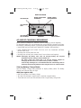
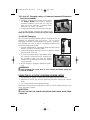
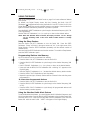
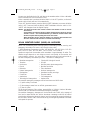
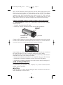
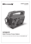
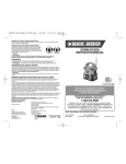
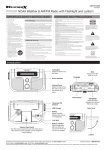
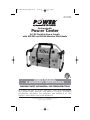
VEC1029FPOB_ManualEN_101606
10/16/06
5:17 PM
Page i
VEC1029POB
VEC1029FPOB
Rechargeable
Power Center
AC/DC Portable Power Supply
with AM/FM and NOAA Weather Alert Radio
USER’S MANUAL
& WARRANTY INFORMATION
IMPORTANT SAFETY INFORMATION, SAVE THESE INSTRUCTIONS
TO REDUCE THE RISK OF INJURY, USER MUST READ AND UNDERSTAND
THIS INSTRUCTIONAL MANUAL. THIS MANUAL CONTAINS IMPORTANT
INFORMATION REGARDING THE OPERATION AND WARRANTY OF THIS
PRODUCT. PLEASE RETAIN FOR FUTURE REFERENCE.
4140 S.W. 30th Ave., Ft. Lauderdale, FL 33312
Toll Free: (800) 544-6986
VEC1029FPOB_ManualEN_101606
10/16/06
5:17 PM
Page 1
IMPORTANT SAFETY INSTRUCTIONS
WARNINGS
TO REDUCE THE RISK OF FIRE, ELECTRIC SHOCK, EXPLOSION OR INJURY:
• This equipment employs components that tend to produce arcs or sparks. DO
NOT install in compartments containing batteries or flammable materials.
• Use this unit in properly ventilated areas ONLY. Do not block ventilation slots.
• DO NOT use the inverter near flammable materials or in locations that may
accumulate flammable fumes or gases.
• Do not open — there are no user-serviceable parts inside.
• Do not insert foreign objects into the outlets.
• Do not expose the unit to flammables, water, rain or snow.
• This inverter has not been tested for use with medical devices.
CAUTIONS
•
•
•
•
•
ALWAYS turn OFF the inverter by disconnecting it from the DC accessory outlet when not in use.
NEVER IMMERSE THE UNIT IN WATER.
DO NOT expose to extreme heat or flames.
DO NOT replace the 12 Volt DC Adapter fuse with one of a higher amperage rating.
Although this unit contains a non-spillable battery, it is recommended that the unit be kept upright
during storage, use and recharging. To avoid possible damage that may shorten the unit’s working
life, protect it from direct sunlight, direct heat and/or moisture.
• Check unit periodically for wear and tear. Take to a qualified technician for replacement of worn or
defective parts immediately.
EXTENSION CORD SAFETY
1. To reduce risk of damage to electric plug and cord, pull by plug rather than cord when
disconnecting from the 120 Volt AC Charger.
2. Use of an improper extension cord could result in a risk of fire and electric shock, and will void warranty.
When choosing an extension cord to use with this unit, make sure it is
properly wired and in good electrical condition.
3. Do not attempt to charge the unit if the 120 Volt AC Charger plug is damaged — return the unit to
manufacturer for repair.
THIS UNIT IS NOT A TOY AND SHOULD ONLY BE OPERATED BY ADULTS. KEEP AWAY FROM CHILDREN!
WEATHER RADIO SAFETY INSTRUCTIONS
WARNING: This product should not be the only source of information for all-hazard, watches and
warnings. If severe weather is imminent; do not wait to receive the weather alert warning, take
precautionary measures to protect yourself.
WARNING: The Weather Radio in this unit is designed to receive NOAA weather and other
emergency alerts as listed on page 10 of this manual and communicate these alerts to you. You may not
receive or clearly hear these alerts under any of, but not limited to, the following circumstances:
• Improper setup (Unit not in Alert Mode, or turned on); make sure that the unit is turned on and the Alert
LED indicator is lit, (see page 9 for Weather Radio instruction).
• Volume is too low; adjust the volume to an audible level using the Volume Control Knob.
• Loss of AC power and/or the internal batteries are dead. Recharge the unit using the DC charging method
on page 6 or using the AC charging method on page 6 following return of AC power. Be sure to
occasionally place the unit back on charge to maximize your runtime in the event of AC power failure.
• Lost or poor reception which can be attributed to any of the following:
a) Improper antenna setup. To ensure you get the best available reception extend the built-in antenna
and adjust its direction to provide maximum reception.
b) Improper tuner setup. To ensure you are always tuned in to receive the NOAA alerts check the
National Weather Service website @ http://www.nws.noaa.gov/nwr/nwrbro.htm for the signal
frequency in your area. If you are on the correct frequency and fail to get a signal, check that you
have power and/or try placing the radio close to a window.
1
VEC1029FPOB_ManualEN_101606
10/16/06
5:17 PM
Page 2
c) Your location is out of range from a weather radio transmitter; the broadcast range from the weather
radio transmitter is approximately 40 miles. The effective range depends on such things as terrain
and
quality
of
the
receiver
and
indoor/outdoor
antenna.
Log
onto
http://www.nws.noaa.gov/nwr/nwrbro.htm to see which frequency best serves your area.
d) Metal structure; to improve the radio’s ability to receive NOAA broadcast; do not place the unit near
any large obstructions or metal surfaces such as refrigerators, metal cabinets, etc. In metal
structures, such as mobile homes, reception is difficult because the metal structure impedes the
transmission of monitor waves, in this case, place the radio close to a window to improve reception.
e) Radio frequency interference; some electronics may cause radio frequency interference such as twoway radios, remote control cars, etc. Place the unit as far away as possible from these devices or
avoid the usage of devices that cause radio frequency interference while the unit is in alert mode.
• If there is excessive background noise while monitoring alerts; or when the alert comes on, adjust the
volume using the Volume Control Knob or relocate the unit to a better location where you can hear
the weather broadcast without risk of interference from background noise.
• If you are out of audible range of or far away from the unit; or if there is an obstruction between you
and the radio, be sure to check the unit for warnings periodically or remain close enough (within
hearing range) to clearly hear and understand the alerts.
WARNING: To ensure to continuously monitor alerts from NOAA while the unit is in alert mode,
the unit should be checked periodically to confirm its functionality and for loss of reception; also check
for loss of reception after moving the unit to a different location.
• Test Warnings from NOAA; all National Weather Services periodically transmit test signals. Some
stations broadcast a test signal every week on Wednesday between 11 AM and 1 PM, while others
test more often, the NWS may also broadcast System demonstrations. You can find out when your
local NWS broadcasts test signals by calling the NOAA National Weather Service Forecast Office
(listed under “Weather” in the Federal Government section of the telephone book.) During the weekly
test signal, the local NWS will give a list of counties covered by their transmitter.
• Check unit periodically for wear and tear. Take to a qualified technician for replacement of worn or
defective parts immediately.
• Read This Instruction Manual Before Using This Unit.
Read This User’s Manual Before Using This Unit.
SAVE THESE INSTRUCTIONS
This device complies with part 15 of the FCC rules. Operation is subject to the following two conditions: (1)
this device may not cause harmful interference, and (2) this device must accept any interference received,
including interference that may cause undesired operation.
This equipment has been tested and found to comply with the limits for a Class B digital device, pursuant to
part 15 of the FCC Rules. These limits are designed to provide reasonable protection against harmful
interference in a residential installation. This equipment generates, uses and can radiate radio frequency
energy and, if not installed and used in accordance with the instructions, may cause harmful interference to
radio communications. However, there is no guarantee that interference will not occur in a particular
installation. If equipment does cause harmful interference to radio or television reception, which can be
determined by turning the equipment off and on, the user is encouraged to try to correct the interference by
one or more of the following measures:
• Reorient or relocate the receiving antenna.
• Increase the separation between equipment and receiver.
• Connect the equipment into an outlet on a circuit different from that to which the receiver is connected.
• Consult the dealer or an experienced radio/TV technician for help.
2
VEC1029FPOB_ManualEN_101606
10/16/06
5:17 PM
Page 3
TABLE OF CONTENTS
Introduction . . . . . . . . . . . . . . . . . . . . . . . . . . . . . . . . . . . . . . . . . .
Features . . . . . . . . . . . . . . . . . . . . . . . . . . . . . . . . . . . . . . . . . . . .
AC and DC Charging/Recharging . . . . . . . . . . . . . . . . . . . . . . . . . .
Viewing Battery Charge Status . . . . . . . . . . . . . . . . . . . . . . . . . . .
120 Volt AC Charging using a Common Household Extension Cord
(not included) . . . . . . . . . . . . . . . . . . . . . . . . . . . . . . . . . . . . . .
12 Volt DC Charging . . . . . . . . . . . . . . . . . . . . . . . . . . . . . . . . .
Using the 12 Volt DC Portable Power Supply . . . . . . . . . . . . . . . . . . .
Using the 120 Volt AC Power Supply . . . . . . . . . . . . . . . . . . . . . . . .
AC Power Supply Controls, Indicators and Operation . . . . . . . . . .
Using the USB Charging Port . . . . . . . . . . . . . . . . . . . . . . . . . . . . . .
Using the Emergency Area Light . . . . . . . . . . . . . . . . . . . . . . . . . . . .
Using the Clock/Alarm Clock . . . . . . . . . . . . . . . . . . . . . . . . . . . . .
Programming the Clock and Alarm Clock . . . . . . . . . . . . . . . . . . .
Using the Radio . . . . . . . . . . . . . . . . . . . . . . . . . . . . . . . . . . . . . . .
Using the Sleep Feature . . . . . . . . . . . . . . . . . . . . . . . . . . . . . . .
Programming Stations Into Memory . . . . . . . . . . . . . . . . . . . . . . .
Using the Weather Radio Alert Feature . . . . . . . . . . . . . . . . . . . . .
Using the Detachable Hand-Crank LED Flashlight . . . . . . . . . . . . . . . .
Care and Maintenance . . . . . . . . . . . . . . . . . . . . . . . . . . . . . . . . . .
Specifications . . . . . . . . . . . . . . . . . . . . . . . . . . . . . . . . . . . . . . . . .
.
.
.
.
.
.
.
.
.
.
.
.
.
.
.
.
.
.
.
.
.
.
.
.
.
.
.
.
.
.
.
.
.
.
.
.
1
1
3
3
.
.
.
.
.
.
.
.
.
.
.
.
.
.
.
.
.
.
.
.
.
.
.
.
.
.
.
.
.
.
.
.
.
.
.
.
.
.
.
.
.
.
.
.
.
.
.
.
.
.
.
.
.
.
.
.
.
.
.
.
.
.
.
.
.
.
.
.
.
.
.
.
.
.
.
.
.
.
.
.
.
.
.
.
.
.
.
.
.
.
.
.
.
.
.
.
.
.
.
.
.
.
.
.
.
.
.
.
.
.
.
.
.
.
.
.
.
.
.
.
.
.
.
.
.
.
.
.
.
.
.
.
.
.
.
.
.
.
.
.
.
.
.
.
4
4
4
5
5
5
6
6
6
7
7
7
7
8
9
9
INTRODUCTION
Thank you for purchasing the VEC1029FPOB Rechargeable Power Center.
Please read this guide carefully before use to ensure optimum performance and
avoid damage to the unit.
FEATURES
• Built-in 400 watt inverter
• Two 120 Volt AC Outlets to power and recharge 110/120 volt AC appliances
• 12 Volt DC Charging Port to power and recharge cell phones and 12 volt DC
appliances
• USB Charging Port to power and recharge USB personal electronics
• Digital AM/FM and NOAA Weather Alert Radio
• Built-in monophonic speaker
• Earphone Jack for private listening
• Built-in powerful LED Area Light for nighttime use
• Detachable Hand-Crank LED Flashlight for nighttime roadside repairs and use in
remote locations without utility power
• Battery charge level indicators
• Requires no maintenance (other than recharging) for optimum operation
• Battery Status LED Indicator displays battery charge level while charging, or
whenever Battery Status Pushbutton is pressed
3
VEC1029FPOB_ManualEN_101606
10/16/06
5:17 PM
Page 4
• UL listed, built-in 120 volt AC charger that works with a standard household
extension cord (not included)
• 12 Volt DC Charging/Power Adapter with built-in storage compartment included
• Rechargeable, non-spillable, heavy-duty, sealed lead acid battery
• Molded high-impact case is tough and durable
Protective Features
• Automatic Overload — Built-in protection against overload — in the event the
AC outlet draws more than 400 watts, power to the unit’s outlet will automatically
shut off.
• Ground Fault Circuit Interrupter (GFCI) — The GFCI protects the unit and the
user by sensing imbalances in a circuit caused by current leakage to the ground
and shuts down the unit’s AC outlet to prevent electrical shock.
• Overheating — Unit automatically shuts down if it exceeds a safe temperature.
• Low Battery — If the battery power level is too low, the AC Power Supply shuts
down automatically.
Front View
RUBBER HANDLE
DC POWER SUPPLY
PORT
UNIT
FRONT PANEL
(SEE DETAILED VIEW
ON PAGE 5)
AM/FM/
WEATHER ALERT
RADIO PANEL
(SEE DETAILED VIEW ON
PAGE 8)
AC POWER
SUPPLY PANEL
(SEE DETAILED VIEW
ON PAGE 7)
Back View
BUILT-IN
TELESCOPING
ANTENNA
BUILT-IN
AC CHARGER
MONOPHONIC
RADIO SPEAKER
DC CHARGING/POWER ADAPTER
STORAGE COMPARTMENT
4
VEC1029FPOB_ManualEN_101606
10/16/06
5:17 PM
Page 5
Unit Front Panel
USB POWER LED
BATTERY CHARGE LEVEL
PUSHBUTTON
BATTERY CHARGE
LEVEL INDICATORS
USB CHARGING
PORT
USB CHARGING PORT
ON/OFF SWITCH
AREA LIGHT
AREA LIGHT
ON/OFF SWITCH
AC AND DC CHARGING/RECHARGING
Use a common household AC extension cord for charging (cord not supplied).
For maximum battery life, we recommend the unit be kept fully charged at all times.
If the battery is allowed to remain in a discharged state, battery life will be shortened.
• MAKE SURE ALL SWITCHES ARE TURNED OFF DURING RECHARGING.
• FULLY CHARGE THE UNIT USING THE 120 VOLT AC CHARGING METHOD
BEFORE FIRST USE.
• Recharge the unit fully after each use.
• Recharge the unit every two months when it has not been used regularly.
Notes: Recharging the battery after each use prolongs battery life; frequent
discharges between recharges reduces battery life.
The Power Center also comes with a 12 Volt DC charging adapter for
recharging the unit from a 12 volt DC accessory outlet in a vehicle.
If unit is fully discharged, it is recommended that the vehicle being used for
recharging be left running while the unit is charged via the 12 volt DC method.
Viewing Battery Charge Status
Press the Battery Charge Level pushbutton to display battery status. The Battery
Charge Level Indicator LEDs will light.
LEDs (from right to left):
• Red LED indicates a low battery charge.
• Two Red LEDs indicate a medium level or partially charged battery.
• Three Red and one Green LEDs indicates a full or high battery charge level.
5
VEC1029FPOB_ManualEN_101606
10/16/06
5:17 PM
Page 6
120 Volt AC Charging using a Common Household Extension
Cord (not included)
1. Lift the AC Charger cover located on the back of
the Power Center and connect a standard
household extension cord to the unit. Plug the
other end of the cord into a standard North
American 120 volt AC wall outlet.
2. Charge until three Red and one Green LEDs light.
3. Once fully charged, disconnect the extension cord.
Note: The unit cannot be overcharged using this method.
12 Volt DC Charging
The 12 Volt DC recharging method will NOT recharge the unit as
effectively as recharging from 120 volt AC. The 12 volt DC
recharging procedure is recommended only when it is necessary,
since frequent use of the 12 volt DC recharging procedure may
shorten the battery system’s life.
1. Insert the gold-tipped DC Charging Adapter end plug into the
vehicle’s 12 volt DC accessory outlet.
2. Insert the silver-tipped end plug into the 12 Volt DC Outlet on
the front panel of the unit.
3. To check the charge status of the battery during
DC charging, disconnect the DC adapter from
the accessory outlet and push the Battery
Charge Level pushbutton. Observe the battery
charge indicator.
4. When charging is complete, remove the power
cord.
WARNING
Do not recharge for more than 5 to 6 hours maximum using the
12 volt DC method.
USING THE 12 VOLT DC PORTABLE POWER SUPPLY
1. Flip open the 12 Volt DC Outlet cover on the upper right side of the unit.
2. Insert the 12 volt DC plug from the appliance (cell phone charger, etc.) into the
outlet.
3. Turn on the appliance and operate normally.
Make sure to disconnect all appliances from the 12 Volt DC Outlet when the unit is
being recharged or stored.
CAUTION
DO NOT USE UNIT TO POWER APPLIANCES THAT DRAW MORE THAN
5 AMPS DC.
6
VEC1029FPOB_ManualEN_101606
10/16/06
5:17 PM
Page 7
USING THE 120 VOLT AC POWER SUPPLY
The Power Center comes with:
1. AC On/Off Switch — Press switch to turn the AC Power
AC POWER
Supply on and off.
SUPPLY PANEL
2. Dual 120 Volt AC Power Outlets.
3. AC Power Supply “ON” Status Indicator (green LED) —
lights when AC outlet is turned on; green LED flashes on
and off when faulted.
4. AC Power Ground Fault Circuit Interrupt (GFCI) — two
three-prong outlets for 110/120 volt AC appliances which shut down inverter if
leakage or ground fault current is detected.
5. Internal protective circuits including:
• Overload and over-temperature shutdown (activated if AC output exceeds 400
watts or the unit overheats)
• AC short-circuit shutdown
• Low voltage shutdown
• A new cooling technology that more efficiently cools the power transistors,
dramatically increasing reliability and product life.
AC Power Supply Controls, Indicators and Operation
The illustration above details the AC Power Supply Panel. The ON/OFF switch turns
the AC power circuitry ON and OFF. It can also be used to reset AC power after
shutdown due to overvoltage, overload or over-temperature condition. The “ON”
status indicator lights when AC power supply is available.
1. Turn power switch to ON (the power indicator lights).
2. Plug in appliance and operate as usual.
Make sure the 120 Volt AC Power Supply switch is in the OFF position when the unit
is being recharged or stored.
Note: The AC power supply shuts down automatically when the battery voltage level
is too low. If the green LED flashes, a faulty condition such as an overload,
overheating or short circuiting has occurred. Turn the AC Power Supply OFF and
unplug the appliance. Wait a few minutes, then turn power back ON.
USING THE USB CHARGING PORT
Both the USB Charging Port and its ON/OFF Pushbutton are located on the unit’s
Front Panel (see page 5).
1. Press the USB Charging Port ON/OFF Pushbutton to turn the USB Port ON. The
red USB Power LED will light.
2. Lift the rubber cover to access the USB Charging Port (on the Front Panel).
3. Plug the USB-powered device into the USB Power Port and operate normally.
4. Press the ON/OFF Pushbutton again to turn the USB Charging Port OFF when
you are finished.
Notes: This unit’s USB Charging Port does NOT support data communication. It only
provides 5 volts/500mA DC maximum power to an external USB-powered
device.
To conserve battery power, ALWAYS turn the USB Charging Port OFF when not
in use.
7
VEC1029FPOB_ManualEN_101606
10/16/06
5:17 PM
Page 8
USING THE EMERGENCY AREA LIGHT
The Area Light is controlled by an ON/OFF pushbutton (both are located on the Unit’s
Front Panel). Make sure the Area Light is turned OFF when the unit is being recharged
or stored.
USING THE CLOCK/ALARM CLOCK
Programming the Clock and
Alarm Clock
By default, the Digital Display shows the time (hours:
minutes (AM/PM), with the seconds displayed in the
upper right corner). Note that the back light will
activate automatically whenever any button is
pressed.
This unit allows the user to program in two separate
alarm times. Each Alarm Clock setting can be
programmed to respond at the programmed time
with either the Alarm sound or automatically turn the
Radio ON (to the last station tuned in).
Before using the Alarm Clock feature, you must
program in the time. Refer to the above enlargement of the Radio Panel to locate
referenced buttons and controls. Make sure the Radio ON/OFF Pushbutton is in the
OFF position, as this puts the unit in Clock mode (where you can program the clock
and alarm time and settings).
Setting Up the Clock
1. Press the MEM/CLOCK Pushbutton once. The numbers on the Digital Display will
blink.
2. Press the HOUR Pushbutton until the correct hour displays (cycling through from
AM to PM).
3. Press the MIN Pushbutton until the correct minute displays.
4. Press the MEM/CLOCK Pushbutton to save. The unit automatically goes to alarm
set-up. Simply press the MEM/CLOCK Pushbutton twice to exit and save all
changes without setting up an alarm time.
Setting Up the Alarm Clock
5. To set the Alarm Clock, press the MEM/CLOCK Pushbutton until the numbers on
the Digital Display blink and “AL1” (Alarm setting 1) appears at the bottom of
the display.
6. Program in the time for the first alarm as outlined in steps 2 through 3 above.
7. Press the MEM/CLOCK Pushbutton to save the first alarm setting. The unit
automatically goes to second alarm set-up. The numbers on the Digital Display
will blink and “AL2” (Alarm setting 2) will appear at the bottom of the display.
8. Program in the time for the second alarm as outlined in steps 2 through 3 above.
9. When finished, press the MEM/CLOCK Pushbutton once more to save all settings.
Alarm Clock Settings
Pressing the “AL1 SET” cycles through the Alarm/Radio/OFF setting for the first alarm.
Pressing the “AL2 SET” cycles through the Alarm/Radio/OFF setting for the second alarm.
8
VEC1029FPOB_ManualEN_101606
10/16/06
5:17 PM
Page 9
USING THE RADIO
Refer to the enlargement of the Radio Panel on page 8 to locate referenced buttons
and controls.
By default, the Digital Display shows the time. Pressing the Radio ON/OFF
Pushbutton ( ) toggles between turning the Radio ON and OFF. When it is ON, the
Digital Display shows the currently selected frequency and station. Note that the back
light will activate automatically whenever any button is pressed.
Press the BAND/ALERT Pushbutton to cycle through to the desired frequency (AM, FM
or WX [Weather]).
Use the TUNING Pushbuttons (+ or –) to cycle up or down to the desired station.
Note: When WX (Weather Band) is selected, the display will show “CH 01” through
“CH 07” indicating which of the seven NOAA weather stations is currently
selected.
Using the Sleep Feature
Press the Radio ON/OFF Pushbutton to turn the Radio ON. Press the SLEEP
Pushbutton. “Sleep” will blink in the upper center and “90” in the right corner of the
Digital Display. Press the SLEEP Pushbutton repeatedly until the desired number of
minutes shows.
Press and hold the SLEEP Pushbutton to show the rest time. To cancel the Sleep feature,
press the SLEEP Pushbutton again.
Programming Stations Into Memory
Up to 10 stations can be programmed into memory.
• Press the Radio ON/OFF Pushbutton to turn the Radio ON.
• Press the BAND/ALERT Pushbutton to cycle through to the desired frequency (AM
or FM).
• Use the TUNING Pushbuttons (+ or –) to cycle up or down to the desired station.
• Press and hold the MEM/CLOCK Pushbutton until a blinking “M” appears on the
Digital Display.
• Press the TUNING Pushbuttons (+ or –) to select the desired memory station number.
• Press the MEM/CLOCK Pushbutton to save the setting.
• Repeat this process (up to 9 times). Stations will be accessed in the order they were
programmed in.
To Access User-Programmed Stations:
• Press the Radio ON/OFF Pushbutton to turn the Radio ON.
• Press the BAND/ALERT Pushbutton to cycle through to the desired frequency (AM
or FM).
• Press the MEM/CLOCK Pushbutton to cycle through all programmed stations until
desired memory number appears.
Using the Weather Radio Alert Feature
To use the Weather Alert feature, you must first select the WX (Weather) frequency and
NOAA weather station. Press the BAND/ALERT Pushbutton to turn the Alert feature ON
while the radio is OFF. Press and hold the BAND/ALERT pushbutton to turn the Alert
feature ON while the radio is ON. “ALERT” will appear on the Digital Display.
9
VEC1029FPOB_ManualEN_101606
10/16/06
5:17 PM
Page 10
You may turn the Radio back ON and listen to the weather station. When a Weather
Alert is received, the unit will sound an Alert.
When a weather alert is received while the Radio is in the OFF position, an Alert will
sound and the Radio will turn ON automatically.
To turn OFF the Alert feature, press the BAND/ALERT Pushbutton once more while the
radio is OFF. Press and hold the BAND/ALERT Pushbutton while the radio is ON.
“ALERT” will disappear from the Digital Display.
Notes: You MUST be tuned to the desired weather radio station in order to use the
Alert feature.
In Alert Mode, the default is the last weather station that was tuned in. The unit
default is “CH 01.” It is recommended that you select the weather station with
the best reception before putting the unit in Alert mode.
When the battery level is LOW, the battery icon and back light will blink and
the radio will be turned OFF after 10 minutes automatically.
NOAA WEATHER RADIO (NWR) ALL HAZARDS
NWR is an all-hazards public warning system, broadcasting forecast, warning and
emergency information 24 hours a day directly to the public.
7 NWR Broadcast Frequencies include: 162.400MHz, 162.425 MHz, 162.450
MHz, 162.475 MHz, 162.500 MHz, 162.525 MHz, 162.550MHz
Broadcast range from the weather radio transmitter is approximately 40 miles. The
effective range depends on such things as terrain and quality of the receiver and
indoor/outdoor antenna. Log onto http://www.nws.noaa.gov/nwr/nwrbro.htm to
see which frequency best serves your area. “All-Hazard” messages are:
• Weather emergencies
• Chemical & biological hazard
• Tornados
• Oil spill
• Hurricanes
• Nuclear power plant emergencies
• Floods
• Maritime accidents
• Blizzards
• Train derailment
• Natural emergencies
• National emergencies
• Earthquakes
• Homeland security warnings
• Forest fires
• Terrorists attacks
• Avalanches
• Civil emergencies
• Technological emergencies
• Amber alerts
Non-weather emergency messages will be broadcast over NWR when:
• (1) public safety is involved
• (2) the message comes from an official government source
• (3) time is critical
The National Response Plan assigns responsibility to NOAA’s National Weather
Service (NWS) to broadcast non-weather emergency messages.
Non-weather emergency messages will be broadcast over NWR at the request of
local and/or state officials who wish to broadcast a message on NWR, the official
provides text information about the hazard and the appropriate response directly to
the local NWS offices. NWS offices have set up pre-arranged agreements to facilitate
and speed the process.
10
VEC1029FPOB_ManualEN_101606
10/16/06
5:17 PM
Page 11
NWR and the Emergency Alert System (EAS) use the same digital protocols, and
NWR is the primary means for NWS alerts to activate the EAS. The Federal
Communications Commission (FCC) amended the EAS rules in 2002 and adopted
numerous codes. NWS introduced the new codes on June 30, 2004. Log onto
https://www.weather.gov/os/eas_codes.shtml for a complete listing of EAS Event
(NWR-SAME) Codes if your receiver is equipped with Digital SAME Technology.
USING THE DETACHABLE HAND-CRANK LED FLASHLIGHT
The VEC1029POB also comes with a detachable Hand-Crank LED Flashlight.
Features include:
• 3 long-life, ultra bright beam LED lights
• Powered by a flip-up, dynamo hand crank (no need to buy batteries)
LED SELECTION
PUSHBUTTON
3 LED LIGHTS
DYNAMO HAND CRANK
(UNDERSIDE OF UNIT)
Charge the LED Flashlight by opening (flipping up) the dynamo hand-crank’s handle
(located on the underside of the flashlight) and hand cranking in a clockwise direction
at a rate of one to two rotations per second (for optimal charging).
Approximately one minute of hand cranking will yield up to 30 minutes of runtime at
the single LED setting or up to 10 minutes of runtime at the 3-LED setting.
The Flashlight’s ON/OFF function and LED settings are controlled by the LED Selection
pushbutton on the top of the Flashlight as follows:
• Depress the LED Selection Pushbutton for the single LED setting (one LED will light).
• Depress the LED Selection Pushbutton a second time for the 3-LED setting.
• Depress the LED Selection Pushbutton a third time to switch the LED Flashlight OFF.
CARE AND MAINTENANCE
Replacement Parts
For replacement parts (batteries, fuses, adapters, etc.), contact Customer Service,
toll-free, at (800) 544-6986.
CAUTION
If the cord, wires, or cables become damaged, return the entire unit to Power On
Board immediately for service/repair.
11
VEC1029FPOB_ManualEN_101606
10/16/06
5:17 PM
Page 12
Fuse Replacement (12 Volt DC Charging/Power Adapter)
1. Remove plug from accessory outlet. Remove the gold cap by turning counterclockwise and lifting off.
2. Remove center pin and spring. Remove fuse.
3. Replace fuse with same type and size fuse (8 amp).
4. Replace center pin and spring inside plug.
5. Replace gold cap by turning clockwise.
Battery Replacement/Disposal
It is recommended that the unit be returned to Customer Service for
battery replacement.
This unit contains a maintenance-free, non-spillable, sealed lead-acid
battery. This battery is fully recyclable and should be accepted at any
location that accepts common automotive batteries. Examples of places
that accept these batteries are: county or municipal recycling drop-off centers, scrap
metal dealers and retailers who sell automotive replacement lead acid batteries.
WARNINGS
Do not dispose of the battery in fire, as this may result in an explosion.
Before disposing of the battery, protect exposed terminals with heavy-duty electrical tape to
prevent shorting (shorting can result in injury or fire).
Do not expose battery to fire or intense heat, as it may explode.
SPECIFICATIONS
12 Volt DC Specifications
Battery:
Internal Battery Type:
Internal Battery Capacity:
Area Light :
Accessory Outlet Protection:
DC Charging Adapter:
12 volt DC rechargeable, maintenance-free
Sealed, AGM lead-acid
12 volt, 19Ah/20 hour rate
Light Emitting Diode (LED)
Self-resetting overload protection
12 volt DC
AC Power Specifications
Output Power:
Output Voltage:
Output Frequency:
Output Waveform:
Overheat Protection:
Overload Protection:
Output Short Circuit
Protection:
400 watts
120 VAC RMS
60 Hz ±4 Hz
Modified sine wave
Yes
Yes
Yes
12
VEC1029FPOB_ManualEN_101606
10/16/06
5:17 PM
13
Page 13
VEC1029FPOB_ManualEN_101606
10/16/06
5:17 PM
14
Page 14
VEC1029FPOB_ManualEN_101606
10/16/06
5:17 PM
Page 15
TWO YEAR LIMITED WARRANTY PROGRAM
This limited warranty program is the only one that applies to this product, and it sets forth all the
responsibilities of Power On Board, regarding this product. There is no other warranty, other than those
described herein. Any implied warranty of merchantability or fitness for a particular purpose on this product
is limited in duration to the duration of this warranty.
This Power On Board product is warranted, to the original purchaser only, to be free of defects in materials
and workmanship for two years from the date of purchase without additional charge. The warranty does
not extend to subsequent purchasers or users. Manufacturer will not be responsible for any amount of
damage in excess of the retail purchase price of the product under any circumstances. Incidental and
consequential damages are specifically excluded from coverage under this warranty.
This product is not intended for commercial use. This warranty does not apply to damage to units from
misuse or incorrect installation/connection. Misuse includes wiring or connecting to improper polarity
power sources.
RETURN/REPAIR POLICY: Defective products may be returned to manufacturer. Any defective product that
is returned to manufacturer within 30 days of the date of purchase will be replaced free of charge. If such
a product is returned more than 30 days but less than two years from the purchase date, manufacturer will
repair the unit or, at its option, replace it, free of charge.
If the unit is repaired, new or reconditioned replacement parts may be used, at manufacturer’s option. A
unit may be replaced with a new or reconditioned unit of the same or comparable design. The repaired or
replaced unit will then be warranted under the terms of the remainder of the warranty period. The customer
is responsible for the shipping charges on all returned items. During the warranty period, manufacturer will
be responsible for the return shipping charges to the customer in the United States.
LIMITATIONS: This warranty does not cover accessories, such as charging adapters, bulbs, fuses and
batteries, damage or defects resulting from normal wear and tear (including chips, scratches, abrasions,
discoloration or fading due to usage or exposure to sunlight), accidents, damage during shipping to our
service facility, alterations, unauthorized use or repair, neglect, misuse, abuse, failure to follow instructions
for care and maintenance, fire, flood and Acts of God.
If your problem is not covered by this warranty, call our Technical Support Department toll free at (800)
544-6986 for general repair information and charges if applicable.
STATE LAW RIGHTS: This warranty gives you specific legal rights. Some states do not allow limitations on
how long an implied warranty lasts or the exclusion or limitation of incidental or consequential damages,
so the exclusions or limitations stated herein may not apply. This warranty gives the purchaser specific legal
rights; other rights, which vary from state to state, may apply.
TO REQUEST WARRANTY SERVICE FOR THIS PRODUCT: Contact Technical Support by telephone, fax or
mail (see below). We suggest that you keep the original packaging in case you need to ship the unit. When
returning a product, include your name, address, phone number, dated sales receipt (or copy) and a
description of the reason for return and product serial number. After repairing or replacing the unit, we will
make every effort to return it to you within four weeks.
WARRANTY ACTIVATION: Please complete Warranty Activation Card and mail to Power On Board. Enter
“VEC1029FPOB” as Model and “Rechargeable Power Center AC/DC Portable Power Supply” as Product
Type. All Power On Board products must be registered within 30 days of purchase to activate this warranty.
Mail the completed registration form, along with a copy of the original sales receipt, to:
BLACK & DECKER
4409 W. Wanda, McAllen, TX 78503
TOLL FREE: 800-544-6986 • Fax: 956-630-0492.
WARRANTY IS NON-TRANSFERABLE.
RD101606
© 2006 VECTOR PRODUCTS, INC.
MADE IN CHINA