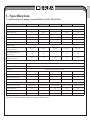
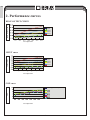
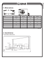
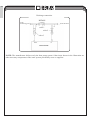
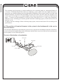
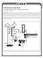
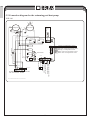
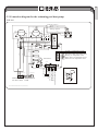
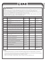
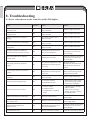
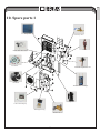
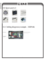
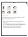
1
EN
POOL EQUIPMENT
KLIN GOTHIC ITC DEMI-13,3 b
zlatá
černá
PANTONE 871 U
Swimming
Pool Heat Pump XHP
PANTONE 426 U
INSTALLATION
AND USER GUIDE
i
Read the instructions
Illustrative photo
EN
Contents
POOL EQUIPMENT
KLIN GOTHIC ITC DEMI-13,3 b
1. Specification...............................................................................................................................................3
2. Performance curves.....................................................................................................................................4
3. Dimensions.................................................................................................................................................5
4. Installation.
..................................................................................................................................................5
zlatá
PANTONE 871 U
5. Electrical černá
connection.PANTONE
..................................................................................................................................9
426 U
6. Initial heat pump start-up and its winterization........................................................................................12
7. Setting operating data...............................................................................................................................14
8.Troubleshooting........................................................................................................................................20
9. Schematic representation and list of parts................................................................................................22
10. Spare parts 1.............................................................................................................................................23
10. Spare parts 2..............................................................................................................................................24
11. Cabling diagram (example – XHP 60)......................................................................................................24
12. Replacement of parts.................................................................................................................................25
Thank you for choosing our product and for your trust in our company. To ensure that you can fully enjoy
the product, please read these instructions carefully and strictly follow the user guide so as not to damage the
device and to avoid unnecessary injuries.
2
EN
1. Specification
1.1 Horizontal heat pump, coolant R410A, ONLY HEATING
POOL EQUIPMENT
KLIN GOTHIC ITC DEMI-13,3 b
Models
XHP 40
XHP 60
XHP 100
XHP 140
XHP 200
3.5
5.0
9.0
12.0
18.0
0.80
1.44
1.92
2.88
6.25
6.25
6.25
6.25
6.25
220−240 V
220−240 V
220−240 V
220−240 V
220−240 V
Nominal current (A)
2.8
4.1
6.7
9.3
13.9
Recommended fuse (A)
10
10
20
20
35
0−15
0−20
25−40
35−60
60−90
Recommended water
flow (m3/hr)
4.2
4.2
6
8.4
10.2
Specification of water inlet/
outlet hose (mm)
50
50
50
50
50
*Capacity at +25°C
Heat output (kW)
zlatá
Heat input (kW)
černá
COP
PANTONE 871 U
PANTONE0.56
426 U
Voltage (V)
*Water data
Recommended swimming
pool volume (m3)
*General data
Compressor
rotary
Air flow
horizontal
Capacitor
titanium heat exchanger in PVC
Noise level in 10 m (dB(A))
35
35
36
37
42
750x325x470
750x325x470
930x360x550
1,000x360x620
1,000x360x855
32
37
50
65
125
855x345x520
855x345x520
1,060x380x600
1,065x380x670
1,165x485x955
37
42
56
72
105
Noise level in 1 m (dB(A))
Water pressure (kPa)
Coolant (kg)
*Dimensions and weight
Net dimensions (mm)
Net weight (kg)
Packaged dimensions (mm)
Gross weight (kg)
The above mentioned data subject to change without notice.
3
EN
2. Performance curves
POOL EQUIPMENT
KLIN GOTHIC ITC DEMI-13,3 b
HEAT OUTPUT (kW)
HEAT OUTPUT curve
XHP 40
zlatá
černá
XHP 60
PANTONE 871 U
PANTONE 426 U
XHP 100
XHP 140
XHP 200
Air temperature
INPUT curve
XHP 40
INPUT (kW)
XHP 60
XHP 100
XHP 140
XHP 200
Air temperature
COP curve
COP
Swimming pool water temperature °C
Air temperature
4
EN
3. Dimensions
POOL EQUIPMENT
KLIN GOTHIC ITC DEMI-13,3 b
Models
zlatá
černá
PANTONE 871 U
PANTONEXHP
42640U
XHP 60
XHP 100
XHP 140
XHP 200
A
273
330
330
380
B
423
680
655
650
C
260
280
300
360
D
293
360
350
410
E
747
930
1,000
1,000
F
210
230
340
560
G
83
83
83
83
H
470
520
590
820
Unit: mm
4. Installation
4.1 Installation illustration
heat pump
water treatment
input for
power cable
side joining valve
output
input
discharge pipe for
condensed water
discharge swimming pool
spout
water feed
water pump
water input
5
filter
EN
Discharge connection
POOL EQUIPMENT
KLIN GOTHIC ITC DEMI-13,3 b
BYPASS
to the
swimming pool
from the filter
valve 1
zlatá
černá
PANTONE 871 U
PANTONE 426 U
valve 2
valve 3
from
to
heat pump
NOTE: The manufacturer delivers only the heat pump system. Other items shown in the illustration are
other necessary components of the water system provided by users or suppliers.
6
EN
ATTENTION:
Please follow the steps below to put the heat pump into operation for the first time:
1.Open the valves to let water into the system.
2. Make sure there is no water leaking in the connections.
3. Run the heat pump with the circulating pump in operation.
POOL EQUIPMENT
KLIN GOTHIC ITC DEMI-13,3 b
zlatá
PANTONE 871 U
4.2 Selection
of the installation
position
černá
PANTONE 426 U
• It is recommended to install the heat pump in a sunny, spacious and well ventilated place.
• Its position has to guarantee the smooth circulation of air (the location of the air inlet is shown in the
diagram below).
• When operated, the heat pump can produce a substantial amount of water condensate and therefore it is
necessary to take its occurrence into account.
• The installation base has to be firm enough to ensure smooth operation of the device.
• Make sure the device, when installed, is situated vertically, without any inclination.
• Do not install the device in places where there is contamination, corrosive gas or where dirt or fallen leaves
accumulate.
• The heat pump must not be installed in the vicinity of an environment with an inflammable or explosive
atmosphere with common fire hazards.
• Maintain the distances from obstacles as indicated with arrows in the next figure.
Ai
r in
Ai
ro
let
utl
et
7
EN
• The swimming pool heat pump is usually installed near the swimming pump at a maximum distance of
7.5 metres. If installed beyond this limit, the technology system (pipes) can cause higher heat losses.
POOL EQUIPMENT Most pipes are installed underground, and although the technology system (pipes) must be provided with
KLIN GOTHIC ITC DEMI-13,3 b
thermal insulation, all tunnels and surrounding soil will still receive the heat, unless the ground is wet
or the water level is high. A very rough estimate of heat losses for 30 metres (15 metres to and from the
pump = 30 metres in total) amounts to 0.6 kW per hour (2,000 BTU) per 5°C of the water temperature
difference in the swimming pool and the ground around the technology (pipes), which increases the run
time by 3 to 5%.
zlatá
PANTONE
871of
U the heat pump system, ensure normal water flow according to the
• To achieve the
best exchange
of heat
černá
PANTONE 426 U
specifications.
4.3 The position of chemical elements in the system is also fundamental to the service
life of the heater.
If an automatic chlorination or bromination system is used, a trap must be installed downstream of the heater.
A water seal must be installed between the chlorinator and the heater to prevent chlorine from returning into
the heat pump (see the following figures).
Pressure chlorination or bromination
Check valve
Chlorinator
Filter
Trap
Water pump
Check valve
8
EN
5. Electrical connection
5.1 Connection diagram for the swimming pool heat pump
POOL EQUIPMENT
KLIN GOTHIC ITC DEMI-13,3 b
XHP 40, XHP 60, XHP 100
red
orange
IMPORTANT: The installation and connection of this device to the power supply can only be provided by
a person that has the electrical qualifications in accordance with Decree No. 50/1978 Coll. Although the heat
zlatá insulated
PANTONE
871rest
U of the unit, this fact only prevents the passage of electrical current
pump is electrically
from the
to or from the černá
water in the
swimming
pool.
PANTONE
426
U It is still necessary to earth the unit, to prepend the circuit breaker
with the current value according to the type of heat pump and current protector with residual current 0.03 A.
Before connecting the heat pump, check whether the electrical mains voltage corresponds to the operating
voltage of the heat pump.
Fan motor
blue
blue
black
Electric expansion
valve
white
black
red
yellow/
green
Compressor
yellow/green
white
brown
OUTPUT1
OUTPUT2
Four-way valve
brown
red
red
blue
RUN/ POWER SUPPLY
OUTPUT3
GROUND
GROUND
black
GROUND
OUTPUT4
GROUND
GROUND
OUTPUT5
Transformer
GROUND
GROUND
GROUND
GROUND
GROUND
GROUND
blue
GROUND
yellow
blue
brown
POWER SUPPLY SINGLE WATER
220−240 V/50 Hz PUMP
Phase sequence protection
High voltage switch
Low voltage switch
Water flow switch
Remote switch
yellow/green
Remote control
blue
*Section marked with dotted lines is only in some models.
9
Cooling coil temperature sensor
Ambient temperature sensor
Returned coolant temperature sensor
Heating coil temperature sensor
Water outlet coil temperature sensor
Water inlet coil temperature sensor
EN
5.2 Connection diagram for the swimming pool heat pump
XHP 140
red
orange
POOL EQUIPMENT
KLIN GOTHIC ITC DEMI-13,3 b
zlatá
černá
Fan motor
te
whi
Electric expansion
valve
red
PANTONE 871 U
PANTONE 426 U
black
black
yellow/green
Compressor
yellow/green
white
blue
blue
brown
OUTPUT1
OUTPUT2
Four-way valve
RUN/ POWER SUPPLY
blue
OUTPUT3
GND
GND
red
GND
OUTPUT4
GND
GND
GND
Transformer
GND
GND
GND
GND
blue
GND
yellow
blue
GND
red
OUTPUT5
brown
A.C. contactor
brown
yellow/green
POWER SUPPLY SINGLE WATER
220−240 V/50 Hz PUMP
Phase sequence protection
High voltage switch
Low voltage switch
Water flow switch
Remote switch
blue
Remote control
red
brown
*Section marked with dotted lines is only in some models.
10
Cooling coil temperature sensor
Ambient temperature sensor
Returned coolant temperature sensor
Heating coil temperature sensor
Water outlet coil temperature sensor
Water inlet coil temperature sensor
EN
5.3 Connection diagram for the swimming pool heat pump
XHP 200
POOL EQUIPMENT
KLIN GOTHIC ITC DEMI-13,3 b
Four-way valveblue
orange
yellow
/green
Fan motor
Starting
capacitor
black
white
blue
A.C. contactor
blue
black
brown
OUTPUT1
OUTPUT2
red
brown
RUN/ POWER
SUPPLY
red
blue
OUTPUT3
GND
blue
GND
brown
Starting
relay
black
blue
red
PANTONE 871 U
PANTONE 426 U
valve
Compressor
zlatá
černá
Electric expansion
red
white
yellow
/green
blue
Starting capacitor
red
GND
GND
OUTPUT4
GND
GND
GND
GND
GND
blue
GND
yellow
blue
GND
OUTPUT5
GND
Transformer
Cooling coil temperature sensor
Ambient temperature sensor
Returned coolant temperature sensor
Heating coil temperature sensor
Water outlet coil temperature sensor
Water inlet coil temperature sensor
brown
*Section marked with dotted lines is only in some models.
11
A.C. contactor
POWER SUPPLY SINGLE WATER
220−240 V/50 Hz PUMP
Phase sequence protection
High voltage switch
Low voltage switch
Water flow switch
Remote switch
yellow/green
Remote control
yellow/green
Crankcase heating
EN
NOTE:
1. The above mentioned connection diagrams are for information only; please use the diagrams delivered
POOL EQUIPMENT
together with the device.
KLIN GOTHIC ITC DEMI-13,3 b
2. The swimming pool heat pump has to be well earthed, although the heat exchanger unit is electrically
insulated from the rest of the unit. In spite of that, it is still necessary to earth the unit to protect yourself
against short-circuits inside the unit.
Disconnection: A disconnector for the unit (circuit breaker or switch with or without a fuse) must be
zlatá
PANTONE 871 U
in sight and easily accessible. This is a standard requirement applicable to both commercial and residential
PANTONE
426device
U from being remotely activated and allows for disconnection of
heat pumps. Itčerná
prevents the
unattended
the unit from the power supply during its maintenance.
6. Initial heat pump start-up and its winterization
NOTE: Please make sure that the filtration pump is running and provides the corresponding level of water
flow.
The START-UP PROCEDURE is completed after installation, so follow the steps below:
1. Switch on the filtration pump, check whether any water is leaking out and check the flow of water
through the system.
2. Connect the power supply to the heat pump and then press the ON/OFF button. After several seconds,
the heat pump should start up.
3. After the heat pump has been running for a few minutes, check whether the air coming out of its side is
cooler (by 5 to 10°C).
4. When you switch off the filtration pump, the heat pump should also automatically switch off. If this is
not the case, adjust the switch setting.
5. Let the heat pump and the swimming pool pump operate for 24 hours a day until the required water
temperature is achieved. After the set temperature is achieved, the heat pump switches itself off. The unit
automatically restarts (if the heat pump is working) if the water temperature in the swimming pool drops
by more than 1°C.
Water flow switch:
The heat pump is equipped with a flow switch, which guarantees the functioning of flow. The flow switch
controls the sufficient amount of water passing through the heat pump. This switch puts the heat pump out
of operation if the water flow is too low in order to prevent the components of the heat pump from being
damaged.
12
EN
Time delay:
The heat pump is equipped with a built-in 3-minute protection against restart. Time delay control is an
integral part of the control circuit, which limits restart cycles and contactor clicking.
POOL EQUIPMENT
KLIN GOTHIC ITC DEMI-13,3 b
Time delay automatically restarts the heat pump approximately 3 minutes after each interruption of the
control circuit. Even a short power failure will activate the 3-minute restart delay and prevent the unit from
activating before the expiry of a period of 3 minutes.
zlatá
PANTONE 871 U
6.1 Heat pump
černáwinterization
PANTONE 426 U
IMPORTANT: If essential measures to prepare the heat pump for winter are not taken, the heat pump could
be damaged, which will void the warranty.
The heat pump, filtration pump, and all installed technology of the swimming pool must not be exposed to
temperatures below the freezing point. It is necessary to remove all water from this whole system (technology),
especially the heat and circulating pump, in an appropriate manner.
We recommend doing the following:
1. Disconnect the power supply to the heat pump.
2. Close the water inlet to the heat pump: completely close valves 2 and 3 in the bypass.
3. Disconnect the connection parts of the heat pump for intake and outlet of water and allow the water to
drain from the heat pump. In the winter season, it is recommended to fit the disconnected heat pump in
a place where temperatures will not fall below freezing point. Warning: always make sure that the water
is fully drained from the heat pump.
4. Loosely reconnect the connection parts for water intake and outlet to/from the heat pump in order to
avoid any pollutants being deposited in the pipes. This is only the case when you have no possibility to
store the heat pump according to item 3.
6.2 Starting up the heat pump again after winter
Before starting the heat pump after winter, first check the technological system (pipes) for passage through.
Also check whether or not the technological parts show any mechanical or other damage.
1. First check whether or not there are any pollutants in the pipes and whether or not there are any
structural problems.
2. Check whether or not the connection parts for water intake and outlet are properly secured to the heat
pump.
3. Start up the filtration pump in order to start the flow of water to the heat pump.
4. Reconnect the power supply to the heat pump and switch it on. Fully open valves 2 and 3 of the bypass.
Keep the circulating pump running until it is full of water. On initial startup, there is bound to be air
present in the technology.
13
EN
7. Setting operating data
POOL EQUIPMENT
KLIN GOTHIC ITC DEMI-13,3 b
7.1 Heating only operation
7.2 Control display functions
1. up and down arrows
zlatá
2. timer on button
černá
PANTONE 871 U
PANTONE 426 U
7
3. timer off button
4. clock button
5. on/off button
1
6
1
6. operating mode display
5
7. LED display
2
3
4
7.3 How to identify the operating parameters (in the event of switching off the heat
pump, the LED display shows real time)
(1) press the
button for 5 seconds and enter the operating parameters interface
(2) in this interface, use the up and down arrows to check the parameters
(3) the temperature of the incoming water (in “on” state) or time (in “off” state) appears on the LED display
after 8 seconds
(4) press the up or down arrows in the current mode to change the water temperature setting both in the on
and off states
(5) if the pump is running, the LED display shows the temperature of the incoming water and the current
mode
14
POOL EQUIPMENT
KLIN GOTHIC ITC DEMI-13,3 b
EN
Parameter 0
setting the temperature for the
incoming water in cooling mode 8 to
35°C, (default setting is 28°C)
zlatá
černá
Parameter 1
setting the temperature for the
incoming water in heating mode 15 to
40°C, (default setting is 28°C)
Parameter 2
total operating time for the compressor after defrosting 30 to 90 minutes,
(default setting is 40 minutes)
PANTONE 871 U
PANTONE 426 U
Parameter 3
conditions for activating the
defrosting function -30 to 0°C,
(default setting is -7°C)
Parameter 4
conditions for deactivating the
defrosting function 2 to 30°C,
(default setting is 20°C)
Parameter 6
mode 0: cooling, 1: heating and
cooling, 2: heating and cooling
and auxiliary heating, 3: heating,
(default setting 3 heating)
Parameter 7
selecting the electronic
expansion valve mode 0 and 1,
(default setting 1 – automatic)
15
Parameter 5
defrosting function deactivation
time 1 – 12 minutes,
(default setting is 8 minutes)
Parameter 8
heat target for super performance
in the range of -15 to 15°C,
(default setting 3°C)
EN
POOL EQUIPMENT
KLIN GOTHIC ITC DEMI-13,3 b
Parameter 9
heat target for super
performance -15 to 15°C,
(default setting 10°C)
zlatá
černá
Parameter A
manual setting of the interval for the
electronic expansion valve 18 to 94,
(default setting 70 (*5))
PANTONE 871 U
PANTONE 426 U
7.4 How to identify the current mode?
Parameter B:
temperature of incoming water
Parameter E:
temperature of returned gas
Parameter C:
temperature of outgoing water
Parameter F:
ambient temperature
16
Parameter D:
capacitor temperature
Parameter G:
capacitor temperature in cooling
EN
POOL EQUIPMENT
KLIN GOTHIC ITC DEMI-13,3 b
Parameter H:
current intervals of the electronic
expansion valve
zlatá
černá
PANTONE 871 U
PANTONE 426 U
NOTE:
1. press the up or down arrow to check the temperature of incoming water, temperature of outgoing
water, capacitor temperature, temperature of returned gas, ambient temperature, current intervals of the
electronic expansion valve
2. when the heat pump is off, the display shows current time
17
EN
7.5 Setting the water temperature
In the current mode, press the up or down arrows to set the water temperature, even if the heat pump is off.
POOL EQUIPMENT
KLIN GOTHIC ITC DEMI-13,3 b
7.6 Setting the locking function
Press the up and down arrow simultaneously to lock the setting. To unlock the setting, press the arrows again
zlatá
PANTONE 871 U
simultaneously.
černá
PANTONE 426 U
7.7 Setting the clock
Press the
button to set the clock and use the up and down arrows to select the values.
To save this setting, press the
button again
7.8 Setting the activation of the timer
Press the
button to set the time for switching on the heat pump and press the up or down arrow to set the
button again. If the LED of this
button is on, then press
interval timing. To save this setting, press the
button to cancel the setting of the timer.
the
7.9 Setting the deactivation of the timer
Press the
button to set the time for switching off the heat pump. Press the up and down arrows to set the
button to save this setting. If the LED of this
button is on, then
time for the switch-off and press the
button to cancel the setting of the timer.
press the
18
EN
ATTENTION:
•It is necessary to check the heat pump operation parameters after the installation and before the first use.
•When the heat pump is running, the LED display shows the temperature of incoming water.
•If you switch off the heat pump using the On/Off button on the control LED display, thus putting the heat
pump into the STANDBY mode, the LED display will show the clock.
•The water temperature may be adjusted when the heat pump is running. Other parameters may only be
changed when the heat pump is in the STANDBY mode.
POOL EQUIPMENT
KLIN GOTHIC ITC DEMI-13,3 b
zlatá
černá
Parameter
Meaning
0
PANTONE 871 U
PANTONE 426 U
Range
Factory setting
Notes
Setting the temperature of incoming water in
cooling mode
8−35°C
28°C
Adjustable
1
Setting the temperature of incoming water in
heating mode
15−35°C
28°C
Adjustable
2
Defrost cycle
30−90 min
40 min
3
Conditions for activating the defrosting function
–30 to 0°C
–7°C
4
Conditions for deactivating the defrosting function
2 to 30°C
20°C
5
Defrost termination time
1 to 12 min
8 min
6
Mode: 0 cooling, 1 heating and cooling, 2 heating
and cooling + auxiliary electric heating, 3 heating
0−3
3 (heating)
7
Electronic expansion valve mode selection
0−1
1 (automatic)
8
Rapid mode for target heating
–15 to 15°C
3°C
9
Rapid mode for target cooling
–15 to 15°C
10°C
A
Intervals for manual adjustments of the electronic
expansion valve
18−94
70
B
Temperature of incoming water
–9 to 99°C
Accurate value
setting
C
Temperature of outgoing water
–9 to 99°C
Accurate value
setting
D
Capacitor temperature in the heating mode
–9 to 99°C
Accurate value
setting
E
Temperature of returned gas
–9 to 99°C
Accurate value
setting
F
Ambient temperature
–9 to 99°C
Accurate value
setting
G
Capacitor temperature in the cooling mode
–
H
Actual intervals of the electronic expansion valve
N*5
Accurate value
setting
Notes:
1. If the heat pumps stops for 30 seconds, the filtration pumps shuts down automatically, if connected.
2. You can also control the filtration pump via the control LED display, provided that the filtration pump is
properly connected to the heat pump via the “PUMP” terminal.
3. In the event of using a 3-phase pump, a special 3-phase converter should be used.
19
EN
8. Troubleshooting
8.1 Error codes shown on the controller with LED display
POOL EQUIPMENT
KLIN GOTHIC ITC DEMI-13,3 b
Fault
Cable
controller
Cause
Solution
Defect to the temperature sensor for
incoming water
PP1
The sensor is either open or
short-circuited.
Check or replace the sensor.
The sensor is either open or
short-circuited.
Check or replace the sensor.
zlatá
PANTONE 871 U
Defect to the temperature
for
černá sensor
PANTONE
426
PP2U
outgoing water
Defect to the sensor for capacitor
heating
PP3
The sensor is either open or
short-circuited.
Check or replace the sensor.
Defect to the sensor for returned gas
PP4
The sensor is either open or
short-circuited.
Check or replace the sensor.
Defect to the sensor for ambient
temperature
PP5
The sensor is either open or
short-circuited.
Check or replace the sensor.
Too large temperature difference
between the inlet and outlet of water
PP6
Insufficient water flow or too
low pressure difference.
Check the volume of water flow
and whether or not the water
passes through.
Too low temperature of outgoing
cooling water
PP7
Insufficient water flow
Check the volume of water flow
and whether or not the water
passes through.
First stage of the frost protection
system
PP7
The ambient temperature or the
temperature of incoming water
is too low.
The pump will run
automatically during the first
stage of the frost protection
system.
Second stage of the frost protection
system
PP7
The ambient temperature or the
temperature of incoming water
is too low.
The heat pump will start heating
during the second stage of the
frost protection system.
Defect to the sensor for cooling
capacitor
PP8
The sensor is either open or
short-circuited
Check or replace the sensor.
Protection against high pressure
EE1
1. Too much coolant
2. Insufficient air flow
1. Remove the excess coolant
from the heat pump system.
2. Clean the air exchanger.
Protection against low pressure
EE2
1. Lack of coolant
2. Insufficient flow
3. Clogged filter or capillary
tubes
1. Check the gas for leakage,
add the coolant.
2. Clean the air exchanger.
3. Change the filter or replace
the capillary tubes.
Defect to the sensor for water flow
EE3
No water / lack of water
Check the volume of water flow
and the pump.
Wrong power supply connection
(for 3-phase unit)
EE4
Wrong or incorrect connection
Check the connection and
power supply cable.
Inlet and outlet temperature
difference error
EE5
Insufficient water flow or too
low pressure difference
Check the volume of water flow
and whether or not the water
passes through.
Communication error
EE8
Wrong connection of cables
Check the connection of cables.
20
EN
8.2 Other faults and solutions (with no display on the controller with LED)
POOL EQUIPMENT
Fault
KLIN GOTHIC ITC DEMI-13,3 b
The heat pump is not
working
zlatá
černá
There is a drop in water
temperature when the
pump is running in the
heating mode.
Display
Cause
Solution
The LED display shows
nothing.
No power supply
Check the connection
of the cable and the circuit
breaker.
The LED display shows
the current time.
The heat pump is in the standby
mode.
Start up the heat pump.
The LED display
shows the actual water
temperature.
1. The water temperature
reaches the set value; the
heat pump is in the constant
temperature mode.
2. The heat pump has just
started up.
3. Defrosting is in progress.
1. Check the setting of the water
temperature.
2. Start up the heat pump
after several minutes.
3. The LED display should
show “defrosting”.
1. Incorrect mode is selected.
2. The values indicate a fault.
3. Controller failure
1. Correct the running mode.
2. Replace the defective cable
controller with the LED
display, then check the
condition after the change
of the running mode,
and check the inlet and outlet
water temperature.
3. Replace the defective main
controller.
PANTONE 871 U
PANTONE 426 U
The LED display shows
the water temperature, but
no error code.
Short run
The LED display shows
the water temperature, but
no error code.
1. The fan is not running
2. Insufficient air ventilation
3. Lack of coolant
1. Check the cable connections
between the motor
and the fan, and replace them,
if necessary.
2. Check the location of the heat
pump unit and remove any
obstruction preventing from
good air ventilation.
3. Replace or repair the heat
pump unit.
Water pollution
Water pollution on the
heat pump unit
1. Water leakage
1. Carefully check the titanium
heat exchanger for damage.
1. Insufficient air ventilation
2. Lack of coolant
1. Check the location of the heat
pump unit and remove any
obstruction preventing good
air ventilation.
2. Replace or repair the heat
pump unit.
Too much ice on the
evaporator
Too much ice on the
evaporator
21
EN
9. Schematic representation and list of parts
POOL EQUIPMENT
Num bComponent
KLIN GOTHIC ITC DEMI-13,3
name
Num
Component name
1
ventilation panel
25
air outlet hose
2
base
26
air return hose
3
central panel
4
zlatá
černá
front panel
titanium tube
to the four-way
PANTONE
871E U
valve
27
PANTONE 426 U
28
air collection tube
from the four-way
valve C to the
capacitor
5
side panel
29
tube from the
capillary tubes
to the liquid
separator
6
capacitor terminal
30
tube from the filter
to the capillary tubes
7
rear panel
31
tube from the filter
to the titanium tube
8
terminal board
32
liquid separator
assembly
9
rear support rod
33
air connection tube
assembly
10
rear grid
34
capacitor
11
motor console
35
fan motor
12
side grid
36
fan blade
13
top cover
37
wiring diagram
14
compressor
38
control panel
15
compressor cover
39
controller
16
nut
40
compressor capacitor
17
shock-proof gasket
41
fan capacitor
18
compressor gasket
42
cable terminals
19
nut
43
cable clamp
20
titanium heat
exchanger in PVC
44
logo
21
electronic
expansion valve
45
name plate
22
filter
46
spring washer
23
Four-way valve
47
nut
24
four-way valve
connection
22
EN
10. Spare parts 1
POOL EQUIPMENT
KLIN GOTHIC ITC DEMI-13,3 b
zlatá
černá
Evaporator
PANTONE
871 U
PANTONE 426 U
Four-way valve
Filter
Plastic water flow switch
Fan motor
Electronic expansion valve
Fan blade
Titanium heat exchanger
Compressor
Control LED display
Watertight casing
Suction valve
23
EN
10. Spare parts 2
POOL EQUIPMENT
KLIN GOTHIC ITC DEMI-13,3 b
manometer
zlatá
černá
high pressure valve
fan motor capacitor
PANTONE
871 U
PANTONE 426 U
low pressure valve
temperature sensors
control unit
11. Cabling diagram (example – XHP 60)
Panel (main controller)
Transformer
Compressor
capacitor
24
EN
12. Replacement of parts
POOL EQUIPMENT
KLIN GOTHIC ITC DEMI-13,3 b
Filter
zlatá
černá
Low pressure valve
Electronic
expansion
valve
PANTONE
871
U
High pressure valve
PANTONE 426 U
Suction valve
Manometer
Important warning:
The components of the heat pump can only be replaced and repaired by a specialized company or an
authorized service centre.
Do not attempt to remove any defects yourself. There is a risk of electrical accident or other hazards.
The device and its components are under constant pressure.
Instructions for replacement:
1. It is necessary to remove all the coolant from the heat pump unit before replacing/changing the
manometer, filter, high/low pressure valve, suction valve and the electronic expansion valve.
2. The replacement can only be carried out when the internal pressure of the system equals the normal
atmospheric pressure.
3. After the filter, high/low pressure valve, suction valve or the electronic expansion valve has been
replaced/changed, silver-solder the connection.
4. Test the gas for leakage under high pressure. (For testing purposes, it is recommended to fill the heat
pump unit with the N2 gas.)
5. After the high-pressure test has been completed, suck the gas out of the heat pump unit.
6. Then refill it with the coolant in the volume as indicated in the unit specifications.
7. Use the detector to recheck the gas for leakage.
8. Complete the replacement and then check the operating data by starting up the unit.
25
EN
Warranty terms and conditions
The warranty conditions are governed by your supplier’s trade and warranty terms and conditions.
POOL EQUIPMENT
KLIN GOTHIC ITC DEMI-13,3 b
Safe disposal of the product after its service life
After its service life is over, have the product disposed of ecologically by a specialized company.
Claims and servicing
Claims are governed by applicable consumer protection legislation. In the event a fault cannot be rectified,
please contactzlatá
your supplier
in writing.
PANTONE
871 U
černá
PANTONE 426 U
Date................................................................
Supplier
26
POOL EQUIPMENT
KLIN GOTHIC ITC DEMI-13,3 b
zlatá
černá
PANTONE 871 U
PANTONE 426 U