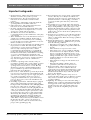
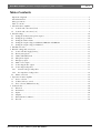
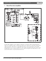
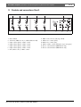
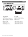
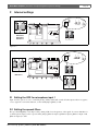
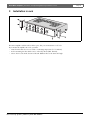
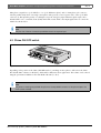
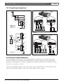
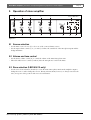
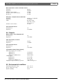
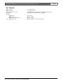
1
Plena Mixer Amplifier
Installation and Operating Manual
en
LBB 1903/10, LBB 1906/10,
LBB 1912/10, LBB 1914/10
Plena Mixer Amplifier | Installation and Operating Manual | Important safeguards
en | 3
Important safeguards
1 Read instructions - All the safety instructions for use
should be read before the system is operated.
2 Retain instructions - The safety instructions and
instructions for use should be retained for future
reference.
3 Heed warnings - All warnings on the unit and in the
operating instructions should be adhered to.
4 Follow instructions - All operating instructions and
instructions for use should be followed.
5 Cleaning - Unplug system units from the mains outlet
before cleaning. Do not use liquid cleaners or aerosol
cleaners. Use a damp cloth for cleaning.
6 Attachments - Do not use attachments not
recommended by the product manufacturer as they may
cause hazards.
7 Water and Moisture - Do not use this unit near water, for
example near a bathtub, washbowl, kitchen sink, or
laundry basket, in a wet basement, near a swimming
pool, in an unprotected outdoor installation or any area
which is classified as a wet location.
8 Accessories - Do not place this unit on an unstable stand,
tripod, bracket or mount. This unit may fall, causing
serious injury to a person and serious damage to the
unit. Use only a stand, tripod, bracket or mount
recommended by the manufacturer, or sold with the
product. Any mounting of the unit should follow the
manufacturer's instructions, and should use a mounting
accessory recommended by the manufacturer. An
appliance and cart combination should be moved with
care. Quick stops, excessive force, and uneven surfaces
may cause the appliance and cart combination to
overturn.
9 Ventilation - Openings in the enclosure, if any, are
provided for ventilation and to ensure reliable operation
of the unit and to protect it from overheating. These
openings must not be blocked or covered. The unit
should not be placed in a built-in installation unless
proper ventilation is provided or the manufacturer's
instructions have been adhered to.
10 Power sources - Units should be operated only from the
type of power source indicated on the marking label. If
you are not sure of the type of power supply you plan to
use, consult your appliance dealer or local power
company. For units intended to operate from battery
power, or other sources, refer to the "Installation and
User Instructions".
11 Grounding or polarisation - This unit may be equipped
with a polarised alternating current line plug (a plug
having one blade wider than the other). This plug will fit
into the power outlet only one way. This is a safety
feature. If you are unable to insert the plug fully into the
outlet, try reversing the plug. If the plug still fails to fit,
contact your electrician to replace your obsolete outlet.
Do not defeat the safety purpose of the polarised plug.
Alternatively, this unit may be equipped with a 3-wire
grounding type plug having a third (grounding) pin.
This plug will only fit into a grounding-type power
outlet. This is a safety feature. If you are unable to insert
the plug into the outlet, contact your electrician to
replace your obsolete outlet. Do not defeat the safety
purpose of the grounding-type lug.
Bosch Security Systems | 2003-09 | 3922 988 92883en
12 Power-Cord Protection - Power supply cords should be
routed so that they are not likely to be walked on or
pinched by items placed upon or against them, paying
particular attention to cords and plugs, convenience
receptacles, and the point where they exit from the
appliance.
13 Overloading - Do not overload outlets and extension
cords as this can result in a risk of fire or electrical shock.
14 Object and Liquid Entry - Never push objects of any
kind into this unit through openings as they may touch
dangerous voltage points or short-out parts that could
result in a fire or electric shock. Never spill liquid of any
kind on the unit.
15 Servicing - Do not attempt to service this unit yourself as
opening or removing covers may expose to dangerous
voltage or other hazards. Refer all servicing to qualified
service personnel.
16 Damage Requiring Service - Unplug the unit from the
outlet and refer servicing to qualified service personnel
under the following conditions:
• When the power-supply cord or plug is damaged.
• If liquid has been spilled, or objects have fallen into
the unit.
• If the unit has been exposed to rain or water.
• If the unit does not operate normally by following
the instructions for use. Adjust only those controls
that are covered by the instructions for use, as an
improper adjustment of other controls may result in
damage and will often require extensive work by a
qualified technician to restore the units to their
normal operation.
• If the unit has been dropped or the unit has been
damaged.
• When the unit exhibits a distinct change in
performance; this indicates a need for service.
17 Replacement Parts - When replacement parts are
required be sure the service technician has used
replacement parts specified by the manufacturer or parts
which have the same characteristics as the original part.
Unauthorised substitutions may result in fire, electric
shock or other hazards.
18 Safety Check - Upon completion of any service or
repairs to the units, ask the service technician to perform
safety checks to determine that the unit is in proper
operating condition.
19 Lightning - For added protection of the units during a
lightning storm, or when it is left unattended and unused
for long periods of time, unplug it from the wall outlet
and disconnect the cable system. This will prevent
damage to the unit due to lightning and power-line
surges.
Plena Mixer Amplifier | Installation and Operating Manual | About this manual
en | 4
About this manual
This manual provides all the information required to install and operate the unit.
Conventions
Warning
Follow these instructions to prevent personal injury.
Caution
Follow these instructions to prevent damage to the equipment.
Note
Read these instructions for tips and other useful information.
Safety precautions
Warning
Do not open the unit when it is connected to the mains. The unit contains non-insulated parts, which can
cause electric shock.
Caution
There are no user-serviceable parts inside the unit. Service must be done by qualified personnel.
Bosch Security Systems | 2003-09 | 3922 988 92883en
Plena Mixer Amplifier | Installation and Operating Manual | Table of contents
en | 5
Table of contents
Important safeguards..........................................................................................................................................................3
About this manual ..............................................................................................................................................................4
Safety precautions...............................................................................................................................................................4
Table of contents ................................................................................................................................................................5
1 About the mixer amplifier ................................................................................................................................................7
1.1
Controls and connections (front) .............................................................................................................................8
1.2
Controls and connections (rear) ..............................................................................................................................9
2 Internal settings ................................................................................................................................................................10
2.1
Setting the VOX for microphone input 1 ............................................................................................................10
2.2
Setting the speech filters .........................................................................................................................................10
2.3
Setting the chime volume ......................................................................................................................................11
2.4
Setting the output voltage for LBB1903, LBB1906 and LBB1912 ....................................................................11
2.5
Setting the output voltage for LBB1914 ...............................................................................................................11
3 Installation in rack ...........................................................................................................................................................12
4 External settings and connections .................................................................................................................................13
4.1
Connect the DC supply (battery) ..........................................................................................................................13
4.2
Priority microphone ...............................................................................................................................................13
4.3
Chime ON/OFF-switch .........................................................................................................................................14
4.4
Microphone inputs ..................................................................................................................................................15
4.5
Emergency input .....................................................................................................................................................15
4.6
Music source inputs ................................................................................................................................................16
4.7
Connecting the line output ....................................................................................................................................16
4.8
Connecting loudspeakers .......................................................................................................................................17
4.8.1 Constant voltage loudspeakers .........................................................................................................................17
4.8.2 Low impedance loudspeakers ..........................................................................................................................18
4.9
Mains connection ....................................................................................................................................................18
5 Operation of mixer amplifier .........................................................................................................................................19
5.1
Source selection .......................................................................................................................................................19
5.2
Volume and tone control .......................................................................................................................................19
5.3
Zone selection (LBB1914/10 only) .......................................................................................................................19
6 Technical data ..................................................................................................................................................................20
6.1
Electrical ..................................................................................................................................................................20
6.2
Performance ............................................................................................................................................................20
6.3
Inputs ........................................................................................................................................................................20
6.4
Outputs .....................................................................................................................................................................21
6.5
Environmental conditions ......................................................................................................................................21
6.6
General .....................................................................................................................................................................22
Bosch Security Systems | 2003-09 | 3922 988 92883en
Plena Mixer Amplifier | Installation and Operating Manual | Table of Contents
Bosch Security Systems | 2003-09 | 3922 988 92883en
en | 6
Plena Mixer Amplifier | Installation and Operating Manual | About the mixer amplifier
1
en | 7
About the mixer amplifier
JP406
JP401
100V
Phantom
Power
100V
0
INS INS
Out In
70V
Click
suppression
70V
70V
JP802
100V
JP402
8 Ohm
0
8 Ohm
0
0
LINE/MIC
JP403
Call Only
0
0
0
LINE/MIC
Mix O nly
JP405
0
+
24V
-
Call Active
24V
201
115V,230V
0
Call Only
0
0
0
Zone 1
Call/Mix
0
0
100V
JP901
100V
Z1 Front
JP902
100/70
70V
70V
8 Ohm
8 Ohm
Call/Mix
0
0
0
0
Zone 2
Call/Mix
0
0
Z2 Front
0
Mix O nly
0
Call Active
24V
0
+
-
24V
Only for LBB1914/10
Figure 1.1
The Plena Mixer Amplifier is a mono amplifier for mixing up to 4 microphone signals and (background) music
signals. You can adjust the volume of each input separately in order to obtain the correct mix and control the mixed
output via the master volume and tone controls. Microphone input 1 can have priority with an optional chime
signal, muting other sources. The power amplifier has a direct output for mixed signals and priority announcements,
but additionally a priority controlled output relay routes the output to loudspeaker zones that should receive only
priority announcements or no priority announcements at all.
Bosch Security Systems | 2003-09 | 3922 988 92883en
Plena Mixer Amplifier | Installation and Operating Manual | About the mixer amplifier
en | 8
1.1 Controls and connections (front)
3
2
4
8
9
Only for LBB1914/10
Plena Mixer Amplifier
1
0 dB
-6 dB
2
Select
CD
AUX
Master
Zone 1
Zone 2
-20 dB
Power
1
3
4
5
Line
6
7
10
11
12
13
Figure 1.2
1
2
3
4
5
6
7
Power button
VU-meter (LED's for -20, -6, 0 dB and Power ON)
Input 1 (microphone) volume control
Input 2 (microphone) volume control
Input 3 (microphone) volume control
Input 4 (microphone) volume control
Line (music source) volume control
Bosch Security Systems | 2003-09 | 3922 988 92883en
8
9
10
11
12
13
Music source selector (CD, tape, AUX)
Master tone control (treble)
Master tone control (bass)
Master volume control (all inputs except emergency)
Zone 1 selection button (LBB1914/10 only)
Zone 2 selection button (LBB1914/10 only)
Plena Mixer Amplifier | Installation and Operating Manual | About the mixer amplifier
en | 9
1.2 Controls and connections (rear)
7
8
9
10
11
12
13
14
L
Tel/Emer.
19
115V
Out
230V
0
R
In
CD
0 2
Aux
+
3
GND
GND
1
1
2
Chime
Inc
Mic/Line
Mic/Line
+
Call Only Mix Only 24VDCIn
Call/Mix
2
3
100V 0
70V
0
8
0 100/70V 0 100/70V 0
1 3
4 5
1
1
Line Out 1V
2
2
3
4
3
5
4
4
5 6
4
5
6
15
Call/Mix
100/70V/8
Zone 1
16 17 18
Zone 2 Call Only Mix Only 24VDCIn
0 100/70V 0 100/70V 0 100/70V 0 100/70V 0
Only for LBB1914/10
15
Figure 1.3
1 Chime ON/OFF switch
2 Priority microphone input (5-pole DIN/balanced
with Phantom power)
3 Input 1 microphone input (6.3 mm phono jack/
balanced with Phantom power)
4 Microphone input (XLR/balanced with Phantom
power in microphone mode)
5 Microphone input (6.3 mm phono jack/balanced)
6 Input Mic./Line switch
7 Emergency connection input terminals
8 Emergency volume pre-set
9 CD input (2x phono connectors)
10 Tape input (2x phono connectors)
11 Auxiliary input (2x phono connectors)
Bosch Security Systems | 2003-09 | 3922 988 92883en
12
13
14
15
16
17
18
19
Line output (XLR)
Tape output (2x phono connectors)
Insertion input/output (2x phono connectors)
Loudspeaker output terminals and 24 Vdc power
supply terminals
Mains connector (3-pole)
Earth connection screw
Mains fuse
LBB1903 T1A (230 Vac) / T2A (115 Vac)
LBB1906 T1.6A (230 Vac) / T3.15A (115 Vac)
LBB1912 T2.5A (230 Vac) / T5A (115 Vac)
LBB1914 T2.5A (230 Vac) / T5A (115 Vac)
Mains voltage 115/230 V switch
Plena Mixer Amplifier | Installation and Operating Manual | Internal settings
2
en | 10
Internal settings
Mic. 3
Mic. 1
JP403
JP405
70V
JP802
JP401
Mic. 2
VOX
JP406
JP402
Mic. 4
100V
1
2 3
100V
Mic. 3
JP405
VOX
JP406
JP802
JP401
Mic. 4
JP402
2 3
70V
JP403
1
Mic. 2
Mic. 1
LBB1903/10
LBB1906/10
LBB1912/10
VR401
1
2 3
OFF
1
2 3
ON
Figure 2.1
Mic. 3
JP401
Mic. 1
JP403
JP405
VOX
JP406
JP402
Mic. 2
Mic. 4
JP902
Mic. 3
JP902
VOX
JP403
JP405
2 3
8 Ohm
JP406
1
JP401
1 2 3
70V/100V
JP402
Mic. 4
Mic. 2
Mic. 1
VR401
2 3
OFF
1
2 3
ON
JP901
LBB1914/10
1
1
2 3
100V
1
2 3
70V
JP901
Figure 2.2
2.1 Setting the VOX for microphone input 1
Input 1 has the option of a voice-controlled priority (VOX), which will overrule all other inputs when it recognizes
a voice signal. To activate this function, set the VOX-jumper (JP406) to ON.
2.2 Setting the speech filters
The speech intelligibility can be improved by cutting off the lower frequencies of the signal. To activate this filter for
each microphone input, set the respective filter jumper (JP401 for input 1, JP402 for input 2, JP403 for input 3 and
JP405 for input 4) to ON.
Bosch Security Systems | 2003-09 | 3922 988 92883en
Plena Mixer Amplifier | Installation and Operating Manual | Internal settings
en | 11
2.3 Setting the chime volume
Adjusting the potentiometer VR401 changes the volume of the chime attention signal, preceding a priority call. Be
careful not to adjust VR701; this is a power amplifier factory adjustment.
2.4 Setting the output voltage for LBB1903, LBB1906 and LBB1912
Direct outputs for 70 V, 100 V and low impedance (8 Ohm) loudspeakers are provided. Jumper JP802 sets the Call
Only and Mix Only outputs to 70 V or 100 V output. These outputs are controlled by a priority relay. The Call
Only output only provides priority announcements, while the Mix Only output just provides the mixed signals and
switches off at priority calls.
2.5 Setting the output voltage for LBB1914
Jumper JP901 sets the Call/Mix, Zone 1, Zone 2, Call Only and Mix Only outputs to 70 V or 100 V output. Setting
JP902 can also set the direct Call/Mix output to 8 Ohm for low impedance loudspeakers. The Call Only and Mix
Only outputs are controlled by a priority relay. The Call Only output only provides priority announcements, while
the Mix Only output just provides the mixed signals and switches off at priority calls. The zone selection buttons
control the outputs of Zone 1 and 2, but priority announcements are always routed to these zones.
Bosch Security Systems | 2003-09 | 3922 988 92883en
Plena Mixer Amplifier | Installation and Operating Manual | Installation in rack
3
Installation in rack
115V
/230
V
Call/M
70
Rate
d
power input
: 400V
A
ix
V0
8
Appa
ra
conn tus deliv
ected ered
for 23
0V-
Call O
nly M
ix Onl
0 10
y 24V
0/70V
DCIn
0 100/
70V
0
Tel/Em
er.
0
Plena
L
R
Mixer
0 dB
-6 dB
-20 dB
0 2
CD
Out
Chime
Ampl
ifier
This
ap
1
Line
In
Out 1V
Mic/Lin
Inc
e
Mic/Lin
1
e
2
paratu
115V/2
30V
3
s mus
t
2
Powe
Aux
1- -3
4 .5
Warni
ng
4
Call/Mi
100V
0 70V
Rated
power input
: 400VA
x
0 8
Apparat
connectus delivere
ed for d
230V-
Call Only
Mix Only
0 100/70
24VD
CIn
V0 100/70
V0
Warning
r
3
This
Selec
t
-
apparatu
s must
be earthed
CD
AUX
+
4
F
Line
1
12 V
D
+
-
+
C
+
12 V
D
Maste
r
LBB1903 (30W); F=F5A
LBB1906 (60W); F=F8A
LBB1912 (120W); F=F15A
LBB1914 (120W); F=F15A
C
Figure 3.1
The mixer amplifier is delivered for tabletop use, but you can mount it in a 19" rack.
If you mount the amplifier in a rack, you must:
• ensure that the unit does not exceed the overheating temperature (45 °C ambient).
• use the mounting brackets which can be ordered by Bosch (LBC 1901/00).
• remove the 4 feet from the bottom of the unit. Without the feet the unit is 2U high.
Bosch Security Systems | 2003-09 | 3922 988 92883en
en | 12
Plena Mixer Amplifier | Installation and Operating Manual | External settings and connections
4
en | 13
External settings and connections
4.1 Connect the DC supply (battery)
115V
/230
V
Call/
70
Rated
power input
: 40 0
VA
Mix
V0
8
Appar
at
conn us deliv
ered
ected
for 2
30V-
Cal O
nly M
ix On
0 10
ly 24
0/70V
VDC
0 100/
In
70V
0
Tel/Em
er.
0
L
R
0 2
CD
Out
Chime
This
Aux
1- -3
4 .5
Warni
ng
Line
In
Out 1V
Inc
Mic/L
ine
Mic/L
ine
1
appa
2
ratus
115V/
230V
3
must
Call/M
4
100V
0 70V
Rated
power input
: 400VA
ix
0
8
Appara
connectus deliver
ted for ed
230V-
Call Only
Mix Only
0 100/70
24VD
CIn
V0 100/70
V0
Warnin
This
12 V
D
+
g
appara
tus must
be earthed
F
-
LBB1903 (30W); F=F5A
LBB1906 (60W); F=F8A
LBB1912 (120W); F=F15A
LBB1914 (120W); F=F15A
+
C
12 V
D
C
Figure 4.1
The mixer amplifier has a 24 Vdc input (terminal screw), which you can use to connect a back up power supply, e.g.
batteries. You can earth the unit to increase the electrical stability of the system.
Caution
The connection cable must have an in-line fuse. Use the type of fuse as mentioned in the illustration.
4.2 Priority microphone
Tel/Em
er.
0
L
R
0 2
2
CD
Out
Chime
Aux
1- -3
4 .5
Line
In
Out 1V
Inc
Mic/Lin
e
Mic/Lin
e
1
2
115V/2
30V
3
4
100V
Rate
d
power input
: 400
VA
Call/Mix
0 70V
0
8
Apparat
conn us deliv
ected
ered
for 230
V-
Call Only
Mix Only
0 100/
24VDC
70V 0
In
100/70V
0
Warning
This
appa
ratus
must
be
earth
ed
GND
GND
6.3 mm phono jack
Figure 4.2
Bosch Security Systems | 2003-09 | 3922 988 92883en
180 5-pole DIN
180 3-pole XLR
Plena Mixer Amplifier | Installation and Operating Manual | External settings and connections
en | 14
Microphone 1 input has a 5-pole DIN (for a 3 or 5-pole DIN microphone) and a 6.3-mm phone jack connector
wired in parallel. Only when connecting a microphone with a priority contact on pin 4 and 5 of the 5-pole DIN
connector (2), this input has priority over all inputs except the emergency input. This microphone input can be
included with a voice controlled circuit (VOX) which will overrule all the other input signals. How to activate the
VOX is described in §2.1.
Note
Only use one of the two connection possibilities of each microphone input.
4.3 Chime ON/OFF-switch
Tel/Em
er.
0
L
R
1
0 2
CD
Out
Chime
Aux
1- -3
4 .5
Line
In
Out 1V
Inc
Mic/Lin
e
Mic/Lin
e
1
2
115V/2
30V
3
4
Call/M
ix
100V
0 70V
0
Rated
power input
: 400
8
VA
Apparat
connec us delivere
ted for
d
230V-
Call Onl
y Mix
Only
0 100
24VDC
/70V
0 100
In
/70V
0
Warnin
g
This
apparat
us mus
t be
earthed
Figure 4.3
Depending on the position of the chime ON/OFF-switch (1), switching on microphone 1 will activate the chime.
The default chime volume is -8 dB (40 V), which will be sufficient in most applications. The volume can be altered
using the potentiometer VR401 on the main PCB of the unit (see §2.3).
Note
Only when connecting a 5-pole DIN microphone to the 5-pole DIN connector of microphone input 1 the
chime can be activated.
Bosch Security Systems | 2003-09 | 3922 988 92883en
Plena Mixer Amplifier | Installation and Operating Manual | External settings and connections
en | 15
4.4 Microphone inputs
6
6
Tel/Em
er.
0
L
R
Tel/E
me
0 r.
L
0 2
CD
Out
Chime
Aux
1- -3
4 .5
Line
In
Out 1V
Inc
Mic/Lin
e
Mic/Lin
e
1
R
2
115V/2
30V
3
4
0 2
Chim
e
CD
Out
Aux
1- -3
4 .5
Line
100V
Rated
power input
: 400VA
Call/Mix
0 70V
0
8
Apparat
connectus delivere
ed for
d
230V-
Call Only
Mix Only
0 100/70V
24VDC
0 100/70V
In
0
Warnin
g
This
apparatu
s must
be earthed
In
Out 1V
Inc
Mic/ Lin
e
Mic/ Lin
1
e
2
3
1
4
Figure 4.4
Dependent on the microphone choose between the XLR with Phantom power and the 6.3 mm phono jack
connector. Use an extension cable (1) if necessary. When using input 3 or 4 to connect microphones, set the
switches (6) to Mic. When using these inputs as line-inputs, set the switches (6) to Line. To cut-off the lower
frequencies of the signal, activate the speechfilters on the PCB (see §2.2).
4.5 Emergency input
8
Tel/Em
er.
0
L
R
0 2
CD
Out
Chime
Tel/ E
mer
0 .
Aux
1- -3
4 .5
Line
In
Out 1V
Inc
Mic/Lin
e
L
Mic/Lin
e
1
2
115V/2
3
4
R
0 2
Chim
e
100V
Rated
power input
: 400VA
Call/Mi
x
0 70V
0
8
30V
Appara
connectus delivere
ted for
d
230V-
Call Only
Mix Only
0 100/70V
24VDC
0 100/70V
In
0
Warnin
This
g
apparat
us must
be earthed
CD
A
1- -3
4 .5
1
2
Figure 4.5
The emergency input is for emergency announcements/signals and obviously has the highest priority (all other
inputs are overruled). The emergency volume -which cannot be affected by the master volume control (11) - can be
set at 8, using a screwdriver. It can not be set to zero.
Caution
A connection to a telephone network must always be made via a telephone coupler that provides adequate
isolation between the telephone network (PBX) and the Plena system. The telephone coupler must also meet
all relevant requirements for this type of communication equipment as imposed by law and/or responsible
telecommunication organisations in the country of use. Never try to make a direct connection between the
telephone network and the mixer amplifier.
Bosch Security Systems | 2003-09 | 3922 988 92883en
Plena Mixer Amplifier | Installation and Operating Manual | External settings and connections
en | 16
4.6 Music source inputs
10
13
Tel/Em
er.
0
L
R
0 2
CD
Out
Chim
e
Aux
1- -3
4 .5
Line
In
Out 1V
Inc
Mic/L
ine
Mic/L
ine
1
Tel/E
mer.
0
2
115V
3
4
Call/M
100V
0 70V
Rated
power input
: 400VA
ix
0
8
Warni
R
This
0 2
/230V
Appar
atus
conne
deliver
cted
ed
for 230V-
Call Only
Mix Only
0 100/70
24VDC
V 0 100/70
In
V0
ng
appara
tus must
be earthe
d
CD
Chim
e
Aux
1- -3
4 .5
Line
Out 1V
Mic/L
ine
Inc
Mic/L
1
in
2
3
CD
RECORD
4
PLAYBACK
LBB1961
PLENA
BGM
Power
TUNER
source
Repeat
Program
Folder
CD/M
TAPE
P3
FM/AM
M1/6
M2/7
M3/8
M4/9
Scan
M5/10
Program
Figure 4.6
When using a CD player, tape recorder or tuner for background music, connect the line-out connectors of the music
source to the appropriate line-in connectors of the mixer amplifier (e.g. the tape recorder must be connected to the
tape source input (10)). When using a tape recorder to record the output of the amplifier, connect the line-in
connectors of the tape recorder to the line-out connector (13) of the mixer amplifier.
4.7 Connecting the line output
12
Tel/E
mer.
0
L
Tel/Em
er.
0
L
R
R
0 2
CD
Out
Chime
Aux
1- -3
4 .5
Line
ne
2
115V/
3
Chim
e
Inc
ne
Mic/Li
1
CD
In
Out 1V
Mic/Li
0 2
4
1- -3
4 .5
Line
Out 1V
Call/M
0 70V
Rated
power input
: 400VA
ix
0
8
230V
Appara
connectus deliver
ed
ted for
230V-
Call Only
Mix Only
0 100/70
24VDC
V 0 100/70
In
V0
Warnin
g
This
apparat
us must
be earthed
Inc
Mic/L
ine
1
100V
Mic/L
in
2
3
Plena
4
Boost
er
0 dB
-6 dB
-20 dB
Amplif
ier
Power
Figure 4.7
The line output (12) is an output for connecting additional PA amplifiers (such as the Plena Booster Amplifiers).
Bosch Security Systems | 2003-09 | 3922 988 92883en
Plena Mixer Amplifier | Installation and Operating Manual | External settings and connections
en | 17
4.8 Connecting loudspeakers
LBB1903/10
LBB1906/10
LBB1912/10
Tel/Em
er.
0
L
R
0 2
CD
Out
Chime
Aux
1- -3
4 .5
Line
In
Out 1V
Inc
Mic/Lin
e
Mic/Lin
1
100V
e
2
115V/2
100V
3
Call/Mi
x
100V
0 70
V
0 8
4
Rated
power input
: 400VA
30V
Apparat
connectus delivere
ed for
d
230V-
Call Only
Mix Only
0 100/70
24VD
V 0 100/70
CIn
V0
Warning
This
0
70V
apparatu
s must
be earthed
70V
70V
JP802
100V
8 Ohm
0
Call Only Mix Only 24VDCIn
Call/Mix
8 Ohm
100V 0 70V
0
8
Call Only Mix Only 24VDCIn
Call/Mix
0 100/70V 0 100/70V 0
100V 0 70V
0
8
0 100/70V 0 100/70V 0
0
0
Call Only
0
0
0
LBB1903/10
LBB1906/10
LBB1912/10
8 Ohm
Mix O nly
4 Ohm
0
+
24V
-
Call Active
4 Ohm
24V
Call/Mix
direct out
100V
Call/Mix
direct out
70V
8 Ohm
8 Ohm
8 Ohm
8 Ohm
Mix Only
100/70V
Call Only
100/70V
Call/Mix direct out 8 Ohm
Figure 4.9
0
Call Only
0
0
0
Zone 1
Call/Mix
0
0
100V
JP901
100V
Z1 Front
LBB1914/10
Tel/Em
er.
0
L
R
0 2
CD
Out
Chime
Aux
1- -3
4 .5
Line
In
Out 1V
Mic/Lin
Inc
e
Mic/Lin
e
1
2
115V/2
3
4
100V
JP902
100/70
70V
70V
30V
Apparat
connectus delivere
ed for
d
230V-
Call Only
Mix Only
24VDC
0 100/70V
In
0 100/70V
0
apparatu
s must
Call/Mix
Call/Mix
100/70V/8
0
0
0
Zone 2
Call/Mix
0
0
Z2 Front
0
Zone 1
Zone 2 Call Only Mix Only 24VDCIn
24V
be earthed
Call/Mix
0 100/70V 0 100/70V 0 100/70V 0 100/70V 0
100/70V/8
Zone 1
Zone 2 Call Only Mix Only 24VDCIn
0 100/70V 0 100/70V 0 100/70V 0 100/70V 0
8 Ohm
4 Ohm
4 Ohm
Mix O nly
0
Call Active
8
This
0
LBB1914/10
0
Warning
8 Ohm
8 Ohm
Rated
power input
: 400VA
Call/Mix
0 70V
0
+
-
24V
Call/Mix
direct out
100/70V
Zone 1
100/70V
Zone 2
100/70V
Call Only
100/70V
8 Ohm
8 Ohm
8 Ohm
8 Ohm
Mix Only
100/70V
Call/Mix direct out 8 Ohm
Figure 4.8
Figure 4.10
4.8.1 Constant voltage loudspeakers
The mixer amplifier can drive 100 V constant voltage loudspeakers at full power (100 V) or half power (70 V).
Connect the loudspeakers in parallel and check the loudspeaker polarity for in-phase connection. The summed
loudspeaker power should not exceed the rated amplifier power. Ensure that the jumper(s) for loudspeaker voltage
selection is / are properly set (see §2.4).
You can use the Call Only output for 3-wire remote volume control override. In this case, ensure that the selected
voltage for the Call Only output is the same as for the direct output or the zone outputs.
Bosch Security Systems | 2003-09 | 3922 988 92883en
Plena Mixer Amplifier | Installation and Operating Manual | External settings and connections
en | 18
4.8.2Low impedance loudspeakers
Connect low impedance loudspeakers to the 8 Ohm/0 terminals. This output can deliver the rated output power
into an 8 Ohm load. Connect multiple loudspeakers in a series/parallel-arrangement to make the combined
impedance 8 Ohm or higher. Check the loudspeaker polarity for in-phase connection. Ensure that the jumper(s) for
loudspeaker voltage selection is / are properly set (see §2.5).
4.9 Mains connection
Tel/E
mer.
0
L
R
0 2
Chim
CD
Out
Aux
e
1- -3
4 .5
Line
In
Out 1V
Inc
Mic/L
ine
Mic/L
ine
1
2
115V
/230V
3
4
100V
Call/M
0 70V
Rated
power input
: 400VA
ix
0
8
Appar
atus
conne
delive
cted
red
for 230V-
Call Only
Mix Only
0 100/70
24VDC
V 0 100/70
In
V0
Warn
ing
This
appara
tus must
be earthe
d
IGN
LIPS&QUA
HOL LITY
LAN
D
115V
/2
30V
Rate
d
powe input
r : 40
0VA
Call O
nly M
ix O
00/70V
0
Appa
ra
conn tus deliv
ered
ected
for 23
0V-
nly 24
VDCIn
100/70
V0
Warni
ng
This
appa
ratus
must
be ea
rthed
Figure 4.11
Use the supplied mains cord to connect the system to the mains supply.
Note
If necessary set the switch 115/230 V to the required voltage using a sharp object, e.g. a small screwdriver.
Bosch Security Systems | 2003-09 | 3922 988 92883en
Plena Mixer Amplifier | Installation and Operating Manual | Operation of mixer amplifier
5
en | 19
Operation of mixer amplifier
3
2
4
8
9
Only for LBB1914/10
Plena Mixer Amplifier
1
0 dB
-6 dB
2
Select
CD
AUX
Master
Zone 1
Zone 2
-20 dB
Power
3
4
Line
Figure 4.6
Use the supplied mains cord to connect the system to the mains supply.
1
5
6
7
10
11
12
13
Figure 5.1
5.1 Source selection
•
•
Use the music source selector (8) to select one of the connected music sources.
Use the input volume controls (3, 4, 5, 6 and 7) to balance the sound level of the microphone inputs and the
background music.
5.2 Volume and tone control
•
•
Use the master volume control (11) to control the volume of the music/microphone mix.
The treble and bass tone controls (9 and 10) affect the microphones as well as the music.
5.3 Zone selection (LBB1914/10 only)
•
Use the zone selection buttons (12 and 13) to route the music/microphone mix from the amplifier output to
loudspeaker zone 1 and/or loudspeaker zone 2. Priority announcements, however, are always routed to both
zones, irrespective of the position of the zone selection buttons.
Bosch Security Systems | 2003-09 | 3922 988 92883en
Plena Mixer Amplifier | Installation and Operating Manual | Technical data
6
Technical data
6.1 Electrical
Mains voltage
Max mains power consumption
LBB1903/10
LBB1906/10
LBB1912/10, LBB1914/10
Max mains inrush current
LBB1903/10
LBB1906/10
LBB1912/10, LBB1914/10
Battery voltage
Max battery current
LBB1903/10
LBB1906/10
LBB1912/10, LBB1914/10
230/115 Vac, ±10%, 50/60 Hz
100 VA
200 VA
400 VA
4.5 A/9 A (230/115 Vac)
5 A/10 A (230/115 Vac)
8 A/16 A (230/115 Vac)
24 Vdc, +20%/-10%
1.6 A
3A
6A
6.2 Performance
Frequency response
Distortion
Bass control
Treble control
50 Hz - 20 kHz (+1/-3 dB @ -10 dB ref. rated output)
< 1% @ rated output, 1 kHz
-8/+8 dB @ 100 Hz
-8/+8 dB @ 10 kHz
6.3 Inputs
Input 1 (5-pin DIN, balanced with phantom power, 6.3 mm phone jack)
Input 2 (3-pin XLR, balanced with phantom power, 6.3 mm phone jack)
Sensitivity
1 mV
Impedance
> 1 kOhm
S/N (flat at max volume)
63 dB
S/N (flat at min volume/muted)
> 75 dB
CMRR
> 40 dB (50 Hz - 20 kHz)
Headroom
> 25 dB
Speech filter
-3 dB @ 315 Hz, high-pass, 6 dB/oct
Phantom power supply
16 V via 1.2 kOhm
VOX (input 1 only)
attack time 150 ms
release time 2 s
Input 3 and 4 (3-pin XLR, balanced with phantom power, 6.3 mm phone jack)
Sensitivity
1 mV (microphone), 200 mV (line)
Impedance
> 1 kOhm (microphone)
> 5 kOhm (line)
S/N (flat at max volume)
63 dB (microphone), 70 dB (line)
S/N (flat at min volume/muted)
75 dB
CMRR
> 40 dB (50 Hz - 20 kHz)
Headroom
> 25 dB
Speech filter
-3 dB @ 315 Hz, high-pass, 6 dB/oct
Phantom power supply
16 V via 1.2 kOhm (microphone)
Bosch Security Systems | 2003-09 | 3922 988 92883en
en | 20
Plena Mixer Amplifier | Installation and Operating Manual | Technical data
Music input (Cinch, stereo converted to mono)
Sensitivity
200 mV
Impedance
22 kOhm
S/N (flat at max volume)
> 70 dB
S/N (flat at min volume/muted)
> 75 dB
Headroom
> 25 dB
Emergency / telephone (Screw, balanced)
Sensitivity
Impedance
VOX
S/N (flat at max volume)
100 mV - 1 V adjustable
> 10 kOhm
threshold 50 mV
attack time 150 ms
release time 2 s
> 65 dB
Interconnection (Cinch)
Nominal level
Impedance
1V
> 10 kOhm
6.4 Outputs
Master output 1 (3-pin XLR, balanced)
Nominal level
Impedance
1V
< 100 Ohm
Tape output (Cinch, 2x mono)
Nominal level
Impedance
350 mV
1.5 kOhm
Interconnection (Cinch)
Nominal level
Impedance
1V
< 100 Ohm
Loudspeaker outputs (Screw, floating)
Max/rated output power 70/100 V
LBB1903/10
LBB1906/10
LBB1912/10, LBB1914/10
8 Ohm output
LBB1903/10
LBB1906/10
LBB1912/10, LBB1914/10
Output power @ 24 V battery operation
45 W/30 W
90 W/60 W
180 W/120 W
16 V (30 W)
22 V (60 W)
31 V (120 W)
-1 dB ref. rated power
6.5 Environmental conditions
Operating temperature range
Storage temperature range
Relative humidity
-10 to +45 °C
-40 to +70 °C
< 95%
Bosch Security Systems | 2003-09 | 3922 988 92883en
en | 21
Plena Mixer Amplifier | Installation and Operating Manual | Technical data
6.6 General
EMC emission
EMC immunity
Acoustic noise level of fan
Dimensions
Weight
LBB1903/10
LBB1906/10
LBB1912/10, LBB1914/10
19” mounting brackets
acc. to EN 55103-1
acc. to EN 55103-2
< 40 dB SPL @ 1 m (LBB1912/10 and LBB1914/10 only)
100 x 430 x 270 mm (19” wide, 2U high)
approx. 5 kg
approx. 8.5 kg
approx. 10.5 kg
LBC1901/00 (to be ordered separately)
Bosch Security Systems | 2003-09 | 3922 988 92883en
en | 22
For more information visit
www.boschsecuritysystems.com
© Bosch Security Systems B.V.
Data subject to change without notice
2003-09 | 3922 988 92883en