1
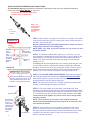
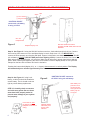
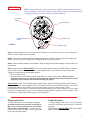
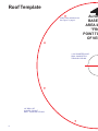
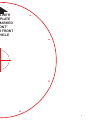
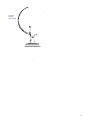
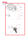
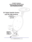
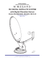
OWNER’S MANUAL
INSTALLATION INSTRUCTIONS
WINEGARD
®
RV DIGITAL SATELLITE SYSTEM
with Digital Elevation Sensor
Models RM-46DE/00DE, RM-04DE, RM-FL4D
U.S. PATENT NO. 5,532,710
Made in U.S.A.
Winegard Company • 3000 Kirkwood St. • Burlington, IA 52601-2000
319/754-0600 • FAX 319/754-0787 • www.winegard.com
Printed in U.S.A. © Winegard Company 2000 2451970 Rev. 2/08/01
1
INSTALLATION & ASSEMBLY
STEP 1. Choose a location on the roof for dish that will allow dish to raise and rotate without
interfering with other roof-mounted equipment. Make sure inside ceiling plate is easily
accessible, and with no obstructions that would interfere with operation.
Figure 1 shows minimum distance (10") antenna should be located from edge
of vehicle roof. It is recommended that you check with your dealer or manufacturer
for provisions that may have been made in the roof for antenna mounting; a
reinforced roof area, or pre-wire installation
from the factory.
The system must be level for
proper operation. Winegard Model
NOTE:
RW-5000 roof wedge with gasket is available. If
inside roof wedge is needed, Winegard’s
RW-1000 can be trimmed to fit ceiling plate.
STEP 2. Position template on roof (pg. 8 this
manual). CAUTION: DO NOT drill through wiring.
Carefully drill a 1-3/4"hole through roof and ceiling
of vehicle. Inspect hole to make sure wiring is
intact. (Roof template, pgs. 8-9.)
2
(4) Antenna
Mounting Bolts
STEP 3. Assemble dish to backup using
bolts and nuts provided, Figure 2.
STEP 4. Mount dish on roof in upright
position. Rotate clockwise to stop, Figure 3.
Dish will be toward back of vehicle when in
stowed or travel position. The word FRONT
is embossed on the base. This should face
front of vehicle. Secure to roof using screws
(provided). The travel bracket should be
mounted to roof 6-1/8" from base of dish,
toward back of vehicle. See Figure 3B.
FIGURE 2
(4) 1/4 - 20
Hex Nut
NOTE: Apply non-hardening sealing compound
to screw heads, coax access hole and edge of
gasket under mount base.
Install the vent tube on the back of the mount
base (This is the side opposite the word
FRONT). The hole for the vent tube is shown
in Figure 3A. CAUTION: DO NOT seal hole
in vent tube. Put sealant around the outside
of the vent tube, approximately 1/2" from end.
Push the vent tube into the hole. The sealant
will seal the hole as you push in. Leave
approximately 2 to 2-1/2" of the vent tube
extending from the hole. Put a small amount
of sealant on the roof under the vent tube end
to hold in place.
FIGURE 3
Measure coax 24" at
plastic fastener on
left side of feed arm.
(See Step 5.)
Rotate
clockwise
to stop
Cable entry plate
placement is 3"
minimum from
mount base.
FIGURE 3A
Sealant
Vent tube
1/2"
CAUTION: DO NOT GET sealing compound
between Base Plate and Rotating Gear Housing.
DO NOT PAINT top of Base Plate or around
Rotating Gear Housing.
FIGURE 3B
Base plate
STEP 5. Facing the front of the dish, note the coax
attached to side of the feed arm. Measure 24" of
coax from this point. Do not cut. Put coax around
mount base, Figure 3. Fasten cable clamp in hole
in mount base (check roof template, page 8, for
correct location) at the end of the coax cable
measure, Figure 3.
6-1/8"
Travel bracket
STEP 6. Apply approved sealing compound over
mounting screw heads.
STEP 7. Feed coax through the roof using cover plate
(included with hardware), Figure 3C. Weatherproof cable
entry by applying sealant under lip of roof-thru plate and
where cable enters roof. Attach plate to roof with screws
provided. Apply sealant over screws and around edge of
roof-thru plate, making sure cable entry is sealed. Secure
cables as necessary to prevent whipping. If downlead
connection must be made on top of roof, make sure to
weatherproof connection!
Rev. 2/08/01
CE-2000
FIGURE 3C
Downlead
#10 x 1" Screws
FS-8100
male-to-male
F-connector
Downlead
connects to
satellite rcvr.
3
DIGITAL ELEVATION SENSOR ROOF CONNECTIONS
The illustrations below show the different methods of connecting wires at roof level. Method will depend on
model. Wire colors MUST MATCH, ie. red to red.
This wire harness connects to the digital
elevation sensor on the antenna.
NOTE: This
terminal is NOT
weatherproof
and CANNOT be
left outside on
the roof.
Snap
connectors
together
INSIDE RV
FIGURE 3D
Ceiling
Measure
these
surfaces
after
pushing
Directional
Handle on Directional
Handle
Elevating
Shaft
Ceiling Plate/
Directional Dial
Elevating
Shaft
FIGURE 3E
There should be no more than 1/32"
between directional handle and
ceiling plate/directional dial. If more
than 1/32", recut directional handle.
FIGURE 3F
STEP 9. The directional handle will fit roofs up to 5-1/4" thick. If you are
using wedges to compensate for roof/ceiling slope, be sure to allow for this
extra thickness. You may add an extension to the directional handle for
thicker roofs. Each extension will increase the length of the directional
handle by 2-1/4".
To install, push directional handle (#4) over elevating shaft and push until
you feel slight resistance. Measure the distance between the directional
handle to the bottom surface of the ceiling plate, Figure 3D. Next, remove
handle and measure that same distance from end of directional handle.
Reduce 3/16" of this measure for proper fit. See Figures 3D and 3E
STEP 10. IF YOU ARE USING AN EXTENSION, adjust the total length of
the directional handle and extension by cutting the directional handle.
After adjusting parts for proper roof thickness, glue the extension to the
directional handle. Use ABS (plastic pipe) glue.
NOTE: For roofs thicker that 6-9/16", a longer aluminum hex shaft will be
needed. Contact Winegard Company for this part.
STEP 11. Flip down handle on the elevating crank handle (#5). Slide
elevating crank handle up shaft until snug against directional handle. Mark
the elevating shaft at inside bottom surface of crank handle housing, Figure
3F. Cut shaft at mark, after removing crank handle. Reinstall crank. After
screw touches shaft, tighten only 1/4 turn more. Screw simply holds
elevating crank on.
NOTE: There should be no more than 1/32" between directional
handle and ceiling plate/directional dial, Figure 3D. If more than 1/32",
recut directional handle.
Elevating shaft
Cut elevating
shaft at inside
surface of
crank handle
housing; shaft
goes through
hex-shaped
opening by
screw.
Crank Handle
4
STEP 8. Check Figure 4 on page 5 for reference to numbers. The circled
numbers show assembly from the ceiling down. Install ceiling plate (#1) to
headliner, using screws (#2 ).
Be sure rotate/lock lever is pointing toward back of vehicle and hole in
ceiling aligns with hole in the ceiling plate.
NOTE: Make sure large and small keyways line up in the hub and
directional handle!
STEP 12. Check system for proper operation. Elevate dish with crank
handle. A minimum of 14 turns is needed to elevate dish. Then, move
directional handle with dish elevated. Directional handle should turn freely.
If possible, have someone watch to make sure coax does not bind or
interfere with dish movement.
1
Ceiling Plate
3
Directional
Handle Extension
2
(4) #10 Phillips Flat
Head Screws
4
Directional
Handle
ALIGN POINTER
WITH ANTENNA
TRAVEL POSITION
5
DIGITAL ELEVATION SENSOR INTERIOR WALLPLATE CONNECTIONS
White
Red
(+) Pos. 12VDC*
(-) Neg. Ground*
Green
Black
* CAUTION: DO NOT
connect a 9 volt battery
if using +12 VDC.
#6 x 5/8"
Phillips Screw
Figure 5
#6 x 1/2"
Phillips Screw
Supplied with
SM-1000
Wallplate Display Unit
SM-1000 Surface Mount Box
Supplied with RM-46DE, RM-FL4D and
EM-00DE
Step 13. See Figure 5. If using the SM-1000 surface mount box, feed cable through hole in box. Connect
wires coming from sensor on roof to wall plate display in coach. Strip wires 1/4". It is IMPORTANT to
connect the wires properly at roof and at wall plate. System is designed to use clean +12 VDC from RV OR
a 9 volt battery (not both). (DO NOT USE power from lighting circuit.) Connect the White, Red, Green,
Black wires before connecting the +12 volt wires. Make sure all wires are in proper place before applying
power. When inserting and tightening the wires into terminals on back of display board, be sure you have
clamped on the bare wire conductor and not the insulation.
Pressing the button should display 24 (+ or - 1 degree) when antenna is in vertical position. The Display
will automatically turn off after approximately one minute.
Step 14. See Figure 6. If using 9 volt
battery, a cable tie should be installed to
secure battery. The tie should not be too
tight to prevent battery replacement.
Figure 6
* CAUTION: DO NOT connect to
+12 VDC if using a 9 volt battery.
Slide battery into
place and cinch
the strap moderately tight around
battery. Clip off
excess tie.
STEP 15. Carefully check connectors
and cable entry points. Be sure these
areas have been properly sealed to
prevent water damage to your system
and property!
Feed cable tie under
the display readout.
(Wallplate not shown for
clarity.)
6
Wallplate display
with battery and
sensor cable
attached.
OPERATION
STEP 1. Step outside your vehicle and, using a compass, determine which direction is
North. (Standing in or near vehicle can give you an incorrect reading.) The more accurately
you determine North, the easier it will be to find the satellite(s).
Directional
Handle
Elevating Crank
Directional Handle
Pointer
Directional Dial
FIGURE 7
Rotation Clamp
Step 2. Using satellite receiver, determine correct elevation for your location. See your receiver manual for
details on how to obtain setup information.
Step 3. Press button on Winegard Digital Display Wall plate. If antenna is in travel position the display will
show LL for Low Limit; HH, for High Limit, will appear when dish is in up position.
Step 4. Crank elevation handle to raise antenna. Stop cranking when readout displays correct elevation for
your location.
Step 5. Rotate antenna VERY SLOWLY until correct satellite signal is acquired. NOTE: Rotate 2° and then
stop. DO NOT rotate continuously, even if you are rotating slowly. If you notice the elevation angle has
changed, it could be due to the following reasons:
1. RV is not parked level.
2. Antenna system is mounted to a slightly sloped RV roof. (This is not a problem. When you have
rotated the antenna so it is facing in approximatly the right azimuth [compass direction], simply
adjust to correct elevation and continue searching for signal.)
Special Notes: When you have detected the satellite signal, adjust the antenna up/down and left/right for
strongest signal your receiver displays. Due to variations in receivers and installation methods, you may find
the elevation numbers, after peaking on the strongest signal, no longer match what the receiver
recommended. This is normal. The elevation sensor should always get you close enough to pick up a signal
to peak on. If display turns off while you’re searching, just push button for another minute of operation. After
a little practice, most people find the signal in 30 to 50 seconds.
Replacement Parts
Trouble Shooting
To order repair parts, contact Winegard Company.
Customer service hours are 7:30 a.m. to 5:00 p.m.,
Mon. - Thu., 7:30 a.m. to 4:00 p.m., Fri., Central Time.
Call toll-free 1-800-288-8094. Credit card only,
minimum $5.00 order. For parts, refer to pages in the
back of this instruction sheet.
• If digital display reads EE, check wiring and
connection. If these are done incorrectly, it will affect
operation.
• Rotate antenna VERY SLOWLY until correct satellite
signal is acquired.
7
Roof Template
Cable clamp attaches here.
See Figure 3, page 3.
ALIGN
BASE
AREA M
"FRO
POINT TO
OF VEH
1-3/4" DIAMETER HOLE;
DRILL COMPLETELY
THROUGH CEILING
1/8" DRILL BIT
8 HOLES. DO NOT
DRILL THROUGH CEILING.
8
N WITH
PLATE
MARKED
ONT"
O FRONT
HICLE
9
10
TUNING ANTENNA
STEP 1. Your receiver should indicate it is receiving a signal. To tune your
antenna for the best signal strength, slowly move the antenna left, then
right until you have found the position that gives the highest signal strength.
It is important to turn the antenna slowly; since the signal is digital the
receiver takes a few seconds to lock on.
STEP 2. Place rotation clamp in the LOCK position. This prevents the
antenna from moving and losing the signal.
STEP 3. Slowly raise, then lower the antenna until you have peaked the
signal. You are now ready to watch satellite TV!
LOWERING ANTENNA TO TRAVEL POSITION
STEP 1. Set rotation clamp to the ROTATE position.
STEP 2. Rotate antenna until pointer on directional handle aligns with
the rotation clamp.
STEP 3. Turn elevating crank (counter clockwise) in direction of "DOWN"
arrow until resistance is met. The number of turns will vary according to
the elevation angle the antenna was set to.
STEP 4. Move rotation clamp to the LOCK position. Antenna is now
locked in travel position.
STEP 5. Snap elevation crank into place.
CAUTION: NEVER LOWER ANTENNA IN ANY POSITION
EXCEPT TRAVEL POSITION.
DO’S
1. Do check parking location for obstructions before raising antenna.
2. Do carefully raise, lower and rotate — if difficult, check for cause.
3. Do rotate slowly when searching for the satellite(s) and check fine tuning
on TV set to make sure it is properly adjusted.
4. Do lower antenna before moving vehicle.
5. Activate programming by calling programming service for your receiver.
DON’T’S 1. Don't move RV/coach with the antenna in the UP position. This will
VOID your warranty. This may also cause damage to your roof.
2. Don’t force elevating crank up or down. Check for cause of trouble.
3. Don’t rotate directional handle hard against stops.
4. Don’t apply paint over top of base plate or anywhere on lift.
5. Don't apply sealing compound on gear housing.
11
12
(2) 1/4-20
Hex Nut
P.N. 2160228
13
PARTS LIST
Location of elevation sensor on RM-46DE,
installed and calibrated at the factory
Mounting
Screws
& Nuts
Sensor
Case
46 cm Reflector, White
Backup
Frame
Sensor
Cable
(4) Flat Head Bolts
(White) P.N. 2160362
Pins and
E-clips
LNBF
P.N. 2745282
Carriage Bolt
P.N. 2160353
(not shown)
Flange Nut
1/4-20
Backup Frame
P.N. 2744939
Roller
P.N. 2200460
Hex Head Bolt
1/4-20 x 2.5"
P.N. 2160237
Feed Arm
P.N. 2744946
Screw #10-24
x 3/4 (4)
P.N. 2160196
Pivot Bracket
P.N. 2744945
Nylock Nut
1/4-20
P.N. 2160220
(not shown)
Pin, 1/4 x 3.25" long
P.N 2160813
(Not shown:
E-clip for 1/4" Pin
P.N. 5160818)
Travel Support
P.N. 2744934
Clamp (2)
P.N. 2590343
Sensor parts w/cable,
installed at factory
Interior wallplate
display and parts
(2) 2160147
#6 x 5/8" Phillips Head Screw
RM-46DE, 2763239
RM-00DE, 2763235
RM-04DE and RM-FL4D, 2763240
(Molex connector
on cable)
(2) 2160183
#10-32 x 1/2"
Screw
(2) 2160216
#10-32 Hex Nut
DR-6400
Wallplate
Display Unit
(2) 2160104
#6 x 1/2" Hex Head
Slotted Screw
SM-1000 Surface
RM-46DE, RM-FL4D,
Mount Box
EM-00DE
RM-46DE, RM-FL4D,
EM-00DE
(7) 2190104
5-1/2" Cable Tie
(1) Supplied with
RM-46DE/00DE
RM-04DE, RM-FL4D
14
(4) 2180183
3M UR Terminal
RM-00DE Only
PARTS LIST
INTERIOR HARDWARE KIT
RP-41RM
Ceiling Base
Directional Dial
(4) #10 Phillip Flat
Head Screws
Azimuth Lock
Azimuth Lock Knob
Directional
Handle
Extension
Washer
#10 x 3/8" Phillips
Directional Handle
Crank Handle Base
#8-32 x 3/8"
Phillips Screw
#8-32 Square Nut
Crank Handle
Knob
#10 x 3/8" Phillips
Screw
Washer
15
SPECIFICATIONS
ANTENNA & MOUNT
Height when raised
Height in the travel position
Operating radius
Roof space required
LNB
Weight
Color
Antenna height
Antenna width
F/D
Offset angle
Frequency range
Gain:
11.2 GHz
12.1 GHz
12.6 GHz
Aperture efficiency
Cross polarization (on axis)
*Beamwidth at -3 dB
*Beamwidth at -10 dB
Wind loading
Ship weight:
30" verticle max.
8" max.
17" (34" diameter circle)
26"
Compatible with DIRECTV® and DISH NetworkTM
12 lbs.
White
20.9"
19.2"
0.59
24o
10.95 - 12.75 GHz
33.22 dBi
33.89 dBi
34.23 dBi
73%
-21 dB
3.5o
7.0o
Up to hurricane force
20.6 lbs.
DIRECTV® is a registered trademark of DIRECTV, Inc., a unit of Hughes Electronics Corporation.
DISH NetworkTM is a trademark of EchoStar Communications Corporation.
ANTENNA/LIFT/LNBF TWO YEAR LIMITED WARRANTY
Printed in U.S.A. Winegard Company • 3000 Kirkwood Street • Burlington, Iowa 52601-2000 © Winegard Company, 2000 2451970 Rev. 2/08/01
16