1
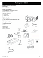
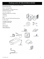
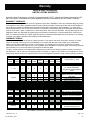
Installation & Operating Manual SF1500A, SF2500A, SF2600A, SF3500A Hot Air Furnaces “Ce manuel est disponible en Français sur demande” SAFETY NOTICE PLEASE READ THIS ENTIRE MANUAL BEFORE YOU INSTALL AND USE YOUR HEATING APPLIANCE. FAILURE TO FOLLOW INSTRUCTIONS MAY RESULT IN PROPERTY DAMAGE, BODILY INJURY, OR EVEN DEATH. FOR USE IN THE U.S. AND CANADA. NOT SUITABLE FOR INSTALLATION IN MOBILE HOMES IF THIS FURNACE IS NOT PROPERLY INSTALLED, A HOUSE FIRE MAY RESULT. FOR YOUR SAFETY, FOLLOW INSTALLATION DIRECTIONS. CONTACT LOCAL BUILDING OR FIRE OFFICIALS ABOUT RESTRICTIONS AND INSTALLATION INSPECTION REQUIREMENTS IN YOUR AREA. CONTACT YOUR LOCAL AUTHORITY (SUCH AS MUNICIPAL BUILDING DEPARTMENT, FIRE DEPARTMENT, FIRE PREVENTION BUREAU, ETC.) TO DETERMINE THE NEED FOR A PERMIT. THIS APPLIANCE IS ALSO APPROVED FOR INSTALLATION INTO A SHOP. SAVE THESE INSTRUCTIONS. R1 3-90-70744R11_05/13 Table of Contents Harman® Central Heating Appliances are built and tested to be complete Home Heating solutions. As with any Central Heat system, a backup heating system may be required in the event of power outages or during appliance service or maintenance. Packing List 3 Installation 5 Mounting Blower & Filter Box 7 Wiring 8 Duct Work 11 Operation 11 Safety Tips 13 Chimney Troubleshooting 13 Maintenance 14 6SHFL¿FDWLRQV Coil Installation 16 Oil Burner Setup 18 Service Parts 19 Warranty 27 Î = Contains updated information 3-90-70744R11_05/13 2 Packing List - SF2600 Blue Angel Oil Burner- (Sold Separately) Burner Gasket Automatic Draft Control Blower - (Sold Separately) (2) Blower Brackets - (Included with blower) Filter Box Kit (3 pieces) + Filter Fan Control / High Limit (2) Thermostats (2) Junction Boxes Relay High Limit Snap Disc (4) 1/4 X 3/4 bolts & (4) Filter Box Mounting Clips Filter 36” Flex Conduit Filter Box Kit (1) Straight Conduit Fitting (1) Elbow Conduit Fitting Filter Box Mounting Clips Ash Pan Shaker Handle Blower Owner’s Manual Warranty Registration Snap Disc Automatic Draft Control Blower Brackets Fan Control / High Limit Thermostats Relay Oil Burner Gasket Oil Burner Ash Pan Shaker Handle Junction Boxes Flex- Conduit and Fittings 3-90-70744R11_05/13 3 Packing List for SF1500, SF2500 & SF3500 Blower Mounting Plate w/ 2 5/16X3/4 bolts ( SF3500 Only) Automatic Draft Control Blower - (Sold Separately) (2) Blower Brackets - (Included with blower) Filter Box Kit (3 pieces) + Filter Fan Control / High Limit 3-Speed Fan Switch (not on SF3500) Thermostat Junction Box Relay (4) 1/4 X 3/4 bolts & (4) Filter Box Mounting Clips Filter 36” Flex Conduit Filter Box Kit (1) Straight Conduit Fitting (1) Elbow Conduit Fitting Filter Box Mounting Clips Ash Pan Shaker Handle Blower Owner’s Manual Warranty Registration Automatic Draft Control Blower Brackets Fan Control / High Limit 3-Speed Fan Switch Thermostat Relay Blower MountSF3500 only Ash Pan Shaker Handle Junction Box Flex Conduit & Fittings 3-90-70744R11_05/13 4 Furnace Installation To ensure a safe installation, it is recommended WKDW WKLV IXUQDFH EH LQVWDOOHG E\ D TXDOL¿HG installer. The sheet metal top and sides can be easily remo ed to reduce the chance of dents or scratches on the painted surfaces 7R UHPRYH WKH VKHHW PHWDO ¿UVW OLIW RII WKH WRS section ow the sides can be remo ed by lifting up and out away from the furnace Inspect Gasket prior to reinstalling heat exchanger To lighten the SF2600 the oil burner heat exchanger VKRXOG EH UHPRYHG 'R VR E\ ¿UVW UHPRYLQJ WKH sheet metal as described abo e Remo e the front VKHHWPHWDOE\¿UVWUHPRYLQJWKHEXUQHUFROODU1RZ remo e the the two long bolts on each side of the heat exchanger (Figure B) The entire unit can now be lifted off and mo ed separately Caution: This furnace must not be installed closer than 24 inches at the sides and 30 inches from the rear to combustible materials. The unit may only be installed on a non-combustible ÀRRUVXUIDFHVXFKDVFRQFUHWHÀRRURUFRQFUHWH SDGRQGLUWÀRRU7KHKRWDLUSOHQXPPXVWEHD minimum of 2 inches from the ceiling or other combustibles above the plenum. Figure A Locate the furnace as close to the chimney as possible while still maintaining the abo e clearances o more than feet of sto epipe should be used including two or less 90 elbows All hori ontal runs of pipe should ha e a minimum 1/4 in rise per foot All sto e pipe must be 24 gauge or thicker When re-installing the heat exchanger inspect the gasket around the furnace opening and replace if necessary (Figure A) Place the heat exchanger in position and secure with the long bolts and nuts Be sure the gasket is compressed e enly Re-install the sheet metal by sliding the groo e on the bottom of each side panel o er the steel lip on the furnace The top sheet metal piece holds the sides in place The SF2600 front co er gets installed by angling the bottom HGJHRYHUWKHOLSRQWKHWRSRIWKH¿UHER[7KHVLGHHGJHVPXVWVOLGHLQWR WKHJURRYHVRQHDFKVLGHDQGSXVKHGLQÀXVKZLWKWKHVLGHVDQGWRS7KLV front piece is held in place by the black ring which gets tightened around the burner pipe Do not o er tighten as this will push the sheet metal in too far (4) 12in bolts two on each side attach the heat exchanger to the furnace Figure B 3-90-70744R11_05/13 5 Furnace Installation Installing Wood/Coal High Limit Switch- SF2600 only First install the sheet metal sides as described in the pre ious section Install the snap disc switch into the hole on the right side sheet metal Then mount the open backed unction box around the snap switch Proceed with wiring as shown on page 10 Also refer to Figure D in this section Mounting The Oil Burner- SF2600 only Remo e oil burner unit from it’s box Loosen the four bolts in the pipe on the front of the furnace Insert the nose of the oil gun into the pipe Before sliding the oil burner all the way in apply the gasket around the nose of the oil gun by wrapping it around the nose ext slide the oil burner into the pipe and secure it by tightening the four bolts around the collar Be sure to tighten the bolts e enly to locate the oil burner LQWKHFHQWHURIWKHSLSH7KH¿QDOVHWXSRIWKHRLOEXUQHU should be done by an experienced oil burner technician with the proper e uipment Refer to the SF2600 wiring diagram on page 10 and the oil burner manual for proper burner setup There is also a section at the end of this manual with VSHFL¿FRLOEXUQHULQVWUXFWLRQV Venting Guidelines. our Harman hot-air furnace must be ented to it’s own VHSDUDWHÀXHOLQHG³&ODVV$´FKLPQH\QRWOHVVWKDQ´;´ in si e The chimney must be capable of pro iding a draft reading of at least 06” water column on a draft meter in order to function properly The Chimney must be a minimum of 16 ft high and must be two feet higher than anything within 10 ft The chimney must also be at least 3 ft higher than the point at which it exits or passes by the roof A EDURPHWULFGDPSHUPXVWEHLQVWDOOHGLQWKHÀXHWRHOLPLQDWH excessi e draft Any hori ontal sections of connector pipe must ha e at least 1/4 in per foot rise Limit the number of elbows to two or less All oints in the connector pipe must be secured with sheet metal screws Assembly. Bolt the shaker handle to the block on the lower left side of the furnace using the bolts and lock-washers pro ided Bolt the automatic draft control to the bottom door Be sure to hold the unit straight while tightening After the automatic draft control is mounted the two wires must be strung through the ÀH[LEOH FRQGXLW DQG WZR ¿WWLQJV VXSSOLHG The knockout plug of the unction box must be remo ed to install WKH FRQGXLW ¿WWLQJ Check the door of the automatic draft control to assure proper operation Warning: Keep pieces of wood or coal out of the draft door opening mechanism as this could cause the door to stick NOTE: Oil the hinge at the begining of the heating season with a light oil The unction box is best mounted on the side of the furnace about 1 in back and in from the top of the sheet metal VLGH¿J&RU',IWKLVORFDWLRQLVLQFRQYHQLHQWDQ\ZKHUH on the right side will work SF1500, SF2500, SF3500. 7KLV ¿JXUH UHSUHVHQWV WKH PRGHOV 6) 6) DQG SF3500 It’s intention is to represent the approximate location of the arious controls This drawing may also be used as a recommendation for routing of the wiring and approximate dimension of control spacing Please note that this drawing is for reference RQO\ (DFK VSHFL¿F installation will ary Bolt the two manual draft controls to the front load door Proper installation allows the draft controls to open approximately 1/2” from the door surface See Figure 1 3-90-70744R11_05/13 6 Furnace Installation SF2600. 7KLV¿JXUHUHSUHVHQWVWKHPRGHO6)IXUQDFH,W¶VLQWHQWLRQ LVWRUHSUHVHQW the approximate location of the arious controls This drawing may also be used as a reference for wiring and control spacing Please note that this drawing is for UHIHUHQFHRQO\6SHFL¿FLQVWDOODWLRQVZLOOYDU\ Mounting The Blower And Filter Box 3RVLWLRQWKH¿OWHUER[EHWZHHQWKHEUDFNHWVRQWKHUHDURIWKHIXUQDFHZLWKWKH ERWWRPRIWKHER[UHVWLQJRQWKHÀDQJHDWWKHERWWRPRIWKHIXUQDFH,QVHUWWKH PRXQWLQJFOLSVLQWRWKHEUDFNHWVORWVWRVHFXUHWKH¿OWHUER[VHH)LJXUH1H[W install the blower brackets onto the blower being sure to install the rubber feet into the brackets OTE On the SF3500 install the blower mount and blower EHIRUHWKH¿OWHUER[All hardware, brackets, etc. for the blower, will be found in the carton with the blower.1H[WSRVLWLRQWKHEORZHULQWKH¿OWHUER[FHQWHUHG behind the inlet hole and allow approximately 1/ in space between the rear of WKH IXUQDFH DQG WKH EORZHU RXWOHW 1RZ LQVWDOO WKH ¿OWHU UDLO RQWR WKH ¿OWHU ER[ 127(7KH¿OWHUUDLOLVEHVWLQVWDOOHGRQWKHVLGHWRZDUGWKHVKDNHUKDQGOHVR WKDW DQ\ SLSHV IURP WKH KRW ZDWHU FRLO GR QRW LQWHUIHUH ZLWK ¿OWHU LQVWDOODWLRQ RU remo al OTE Before proceeding with the installation of the access door it is suggested that the wiring be completed 7KH DFFHVV GRRU LV LQVWDOOHG E\ VOLSSLQJ WKH ÀDQJH RQ WKH ERWWRP RI WKH DFFHVV GRRURYHUWKHERWWRPUDLORIWKH¿OWHUER[RSHQLQJWKHQSXVKWKHWRSRIWKHGRRUDJDLQVWWKHWRSRIWKH¿OWHUER[RSHQLQJDQG secure with a sheet metal screw Filter box mounting clips Figure 2 1/8 in. space between blower and furnace 3-90-70744R11_05/13 7 Furnace Installation - Wiring Wiring %HIRUHEHJLQQLQJDQ\ZLULQJVWXG\WKHDSSURSULDWHZLULQJGLDJUDPIRU\RXUXQLW$OVRUHIHUEDFNWR¿JXUHV&RU'IRUDQ example of what the completed ob will look like It is your reponsibility to follow all state and local electrical codes. /RFDWHWKHEHVWSODFHWRURXWHWKHSRZHUIRUWKHEORZHUDQGGULOOD´KROHLQWKH¿OWHUER[7KLVKROHVL]HZLOODFFRPRGDWH D³URPH[´FRQQHFWRU$WWDFKWKHEORZHUDQGSRZHUZLUHVDVVKRZQRQWKHDSSURSULDWHZLULQJGLDJUDP Once you ha e the plenum installed the fan control with high limit switch can be installed The Fan control/high limit switch is packaged with a umper between the two sets of terminals inside REMO E THE J MPER WIRE I SIDE THE FA CO TROL The fan control should be installed in the right side of the plenum and 12 to 1 inches abo e the top of the furnace A separate conduit should be run from the fan control to the unction box Mount the thermostat in a central location of the area you want to heat Run two wires to the unction box from the heating terminals on the thermostat 22 gauge or thicker wire is acceptable The next step is to run a 120 olt line from your breaker panel to the unction box Attach all wires according to the corresponding wiring diagram and install the relay into the unction box DO OT T R O THE BREAKER TIL ALL WIRI G IS COMPLETE A D THE RELA IS SEC RED SF1500 and SF2500 Wiring Diagram 3-90-70744R11_05/13 SF3500 Wiring Diagram 3-90-70744R11_05/13 9 SF2600 Wiring Diagram 3-90-70744R11_05/13 10 Duct Work and Operating Instructions Duct Work. 7KLV ¿JXUH VKRZV D W\SLFDO GXFW V\VWHP layout Be sure the entire system is properly si ed to pro ide the correct static pressure for optimum blower performance Ha e Return Air any new duct system designed by a H AC professional Supply Trunk Operating Instructions Plenum Adjusting Automatic Draft Control - In order for your new furnace to function the controls must be properly ad usted The heat output is regulated by the automatic draft control on the bottom door of the furnace 5HIHUWRWKHLOOXVWUDWLRQVDWULJKW7KHHOHFWULF GUDIWPRWRU$RSHQVDQGFORVHVWKHÀDSSHU GRRU%7KHÀDSSHUGRRURSHQVWRIHHGPRUHDLUWRWKH¿UHDQGFORVHVWRUHGXFHWKHDLUWRWKH ¿UH7KHPD[LPXPDLUÀRZFDQEHDGMXVWHGE\WXUQLQJWKHDGMXVWHUEROW&FRXQWHUFORFNZLVH for more air and clockwise for less air OTE To preser e motor life all ad ustments of this EROWVKRXOGEHGRQHZKLOHWKHÀDSSHUGRRULVLQWKHFORVHGSRVLWLRQ7KHLGOHDGMXVWHU' FRQWUROVWKHPLQLPXPDPRXQWRIDLUWKDWHQWHUVWKH¿UHER[ZKHQWKHÀDSSHUGRRULVFORVHG Ad ustment is made by turning the ad uster ertical for ero air or hori ontal for maximum idle air It is best to start at a medium setting as shown at right Adjusting the fan control- Shut off the power at the circuit breaker before remo ing the fan control co er Make sure the copper umper (circled below) is remo ed before using the furnace ote the three pointers on the dial The one on the right is the high limit ad ustment Figure 6 3UHVHWDWGHJUHHVLW¶VIXQFWLRQLVWRFORVHWKHDXWRPDWLFGUDIWFRQWUROÀDSSHUGRRULIWKH temperature in the plenum reaches 200 degrees Do not change this setting. The center pointer ad usts the temperature at which the blower starts A good initial setting for this is 150 degrees The pointer on the left is to ad ust the temperature at which the blower stops A good initial setting for this pointer is 100 to 110 degrees If it is set too low the air will feel cool coming out of the registers at the end of the blower cycle Figure 7 3-90-70744R11_05/13 Thermostat- Set the thermostat to the desired temperature When more KHDWLVQHHGHGWKHWKHUPRVWDWRSHQVWKHDXWRPDWLFGUDIWFRQWUROÀDSSHU GRRU7KLVDOORZVDLULQWRWKH¿UHER[ZKLFKUDLVHVWKHRXWSXWRIWKH¿UH When the temperature in the plenum reaches the set temperature of the center pointer on the fan control the blower will begin blowing heated air through the ductwork When the thermostat reaches it’s setpoint the DXWRPDWLFGUDIWFRQWUROFORVHVWKHÀDSSHUGRRUWKXVUHGXFLQJWKHRXWSXW RIWKH¿UH$VWKHWHPSHUDWXUHLQWKHSOHQXPGURSVWRWKHVHWSRLQWRI WKHOHIWSRLQWHURQWKHIDQFRQWUROWKHEORZHUZLOOVWRS$VROLGIXHO¿UH cannot cease output immediately therefore your room temperature may exceed the thermostat setting at times ou also may notice times that the blower runs for a short period e en though the draft control LVFORVHG$JDLQ\RXFDQ¶WMXVWVWRSDZRRGRUFRDO¿UHLQVWDQWO\DQG temperature may build enough to run the blower This is normal and will be noticed more with coal than with wood Figure 5 ZERO MED MAX 11 Operating Instructions SF 2600 - Oil Operation as Backup The SF 2600 offers a uni ue option to the homeowner The DELOLW\WRKDYHDQHI¿FLHQWRLOEDFNXSKHDWVRXUFHEXLOWULJKW into a wood/coal furnace The operation of the oil burner as a backup system is as simple as setting a thermostat To use the oil portion of your furnace as a backup proceed as follows 1 Set the wood/coal thermostat to the comfort le el you desire 2 Set the oil thermostat to a le el 5 to 10 degrees but not less than 3 degrees lower than the wood/coal thermostat That’s all there is to it The idea is that when the wood/coal portion can no longer maintain the le el set on that thermostat the oil portion will come on and maintain the temperature set on the oil thermostat SF 2600 - Oil Operation Only - In the oil only mode simply turn the wood/coal thermostat to its lowest setting and select the comfort le el you desire on the oil thermostat The SF 2600 will now act as a standard oil burner and maintain your chosen temperature OTE It is recommended that the ZRRGFRDO¿UHLQWKHORZHUSRUWLRQRIWKHIXUQDFHEHRXWRU QHDUO\RXWEHIRUHJRLQJWR³RLORQO\´RSHUDWLRQ Curing Paint 'XULQJWKH¿UVWIHZKRXUVRIEXUQLQJDEOXH smoke will be obser ed rising from the painted surface of the furnace It is ad isable to increase the amount of fresh air in the room during this breaking-in period This may be achie ed by opening doors windows etc Don’t be alarmed This is normal Starting a Wood Fire - Open the bottom door to increase the draft Take about eight sheets of newspaper crumbled into balls and place on top of the grates ext lay some ¿QHNLQGOLQJRQWRSRIWKHSDSHU7KLVNLQGOLQJPXVWEHGU\ and no larger than 3/4” diameter and should be layered in DFULVVFURVVSDWWHUQWRDOORZJRRGDLUÀRZ7KHQOD\VRPH slightly larger pieces (2” diameter) of wood on top of the kindling Light the paper at the bottom ust inside the door ow close loading door and allow kindling and wood to FDWFK¿UH$IWHUDERXW¿YHPLQXWHVFORVHWKHERWWRPGRRU and open the loading door an inch or two for a few seconds before opening completely This method will allow the smoke WRFOHDUDZD\IURPWKHGRRURSHQLQJ1RZWKH¿UHVKRXOGEH well established and ready for some larger wood Add four RU¿YHSLHFHVRI´WR´GLDPHWHUZRRG&ORVHORDGLQJGRRU and open bottom door again Let burn for about 5 minutes ow open loading door using the same method as before always closing the bottom door before opening the top door 1RZORDGWKH¿UHER[ZLWKZRRGWRWKHGHVLUHGIXOOQHVV$OO Harman furnaces may be loaded with wood as full as possible for high output and long burn time Then close the door and DOORZDOOWKHZRRGWRFDWFK¿UH7KHERWWRPGRRUPD\DJDLQEH opened to speed the process The ob ect is to get the wood burning well enough so it will not go out when the automatic draft shuts back to the idle setting OTE When the bottom 3-90-70744R11_05/13 door is open the automatic draft cannot function to reduce WKHDPRXQWRIDLUWRWKH¿UHER[)RUWKLVUHDVRQWKHIXUQDFH could o erheat WARNING: NEVER LEAVE THE BOTTOM DOOR OPEN WHILE FURNACE IS UNATTENDED! After the wood is burning well close the bottom door The DXWRPDWLF GUDIW FRQWURO ZLOO QRZ UHJXODWH WKH ¿UH 7KH LGOH FRQWURO DV VKRZQ RQ )LJ RQ WKH ÀDSSHU GRRU PXVW EH DGMXVWHGVRWKH¿UHGRHVQRWJRRXWRURYHUKHDW([SHULHQFH will dictate the best setting ormally the two manual draft controls on the loading door are kept closed to burn wood 6WDUWLQJ$&RDO)LUH se the same procedure as for wood except do not go to large diameter wood se wood about 2” in diameter maximum This si e will form ery hot wood coals in less time Here again the bottom door may be opened to speed the process When a substantial bed of red wood coals are de eloped start adding a thin layer of coal Pea or nut VL]HGFRDOLVEHWWHUIRUVWDUWLQJD¿UHWKDQVWRYHFRDO:KHQ WKH¿UVWOD\HULVEXUQLQJZLWKVRPHEOXHÀDPHFRQWLQXHWR add thin layers of coal until there is a solid bed of burning FRDO/HWHDFKOD\HUEXUQDEOXHÀDPHEHIRUHDGGLQJDQRWKHU layer Layers can be added until the bed is approximately ten LQFKHVGHHS7KLVLVDERXWDWWKHWRSRIWKH¿UHEULFN0RVW XVHUV¿QGWKDWLIWKH\NHHSWKHWZRPDQXDOGUDIWFRQWUROVRSHQ about one uarter turn it helps keep the gasses burned off 127( Close the bottom door as soon as the desired coal bed is made Loading - Coal should ne er be added unless there is a UHDVRQDEO\KRW¿UH7KHFRDOEHGVKRXOGEHEULJKWDQGYLJ RURXV,IWKH¿UHLVEXUQLQJKRWDQGWKHUHLVDGHHSEHGRI coals full loads of coal can be added at any time Howe er if there is not a deep bed of coals it is best to add small DPRXQWVRIFRDODW¿UVW Shaking - Shaking should be done only when there is a wellHVWDEOLVKHG¿UH7KHIUHTXHQF\RIVKDNLQJZLOOGHSHQGRQWKH degree of burning Shaking should be done whene er the furnace is refueled Best results for shaking Harman grates will occur when short choppy strokes are used rather than long e en strokes 12 Operating Instructions/Safety Tips The amount of shaking is critical Too much will disrupt the ¿UHEHGDQGWRROLWWOHZLOOUHVWULFWWKHDLUÀRZ 7KHSURSHUDPRXQWQRUPDOO\RFFXUVZKHQUHGFRDOV¿UVWVWDUW to drop through the grates into the ash pan Ashes - Ashes should ne er be allowed to accumulate in the DVKSLWVRWKDWWKH\LQDQ\ZD\LPSHGHWKHÀRZRIFRPEXVWLRQ DLUWRWKH¿UH([FHVVDVKDFFXPXODWLRQFDQFDXVHWKH¿UH to go out and also can cause se ere damage to the grates EHFDXVHRIWKHDEVHQFHRIDFRROLQJÀRZRIDLUEHQHDWKWKHP Ashes should be placed in a metal container with a tight ¿WWLQJOLG7KHFORVHGFRQWDLQHURIDVKHVVKRXOGEHSODFHG RQDQRQFRPEXVWLEOHÀRRURURQWKHJURXQGZHOODZD\IURP DOOFRPEXVWLEOHPDWHULDOVSHQGLQJ¿QDOGLVSRVDO,IWKHDVKHV are disposed of by burial in soil or otherwise locally dispersed they should be retained in the closed container outside the dwelling) until all cinders ha e thoroughly cooled CAUTION: ASHES SHOULD NEVER BE ALLOWED TO ACCUMULATE ABOVE THE TOP OF THE ASH PAN. ASHES IN CONTACT WITH THE BOTTOM OF THE GRATES ACT AS AN INSULATOR, INTENSIFYING THE HEAT ON THE GRATES, AND COULD CAUSE THEIR WARPAGE. WITH AN EXCESSIVE ASH BUILDUP, PRIMARY COMBUSTION AIR IS RESTRICTED. THUS THE UNIT’S OUTPUT COULD BE REDUCED. Coal produces considerably more ash than wood So the inter als between emptying are much shorter For e ual heat output coal will produce se en to ten times more ash than wood Draft Control Settings - The idle air ad ustment on the ÀDSSHUGRRUPD\QHHGWREHDGMXVWHGVOLJKWO\OHVVIRUFRDO than for wood Here again experience will dictate the best setting The maximum air ad ustment bolt can be set at the maximum position for uick reco ery When a longer than normal burn time is desired the maximum air ad ustment can be reduced e er ad ust the PD[LPXPDLUEROWZKHQWKHÀDSSHUGRRULVRSHQHG6HH)LJ 6 on page 11 Safety Tips When opening the loading door it should be cracked open slightly for a few seconds to allow oxygen to burn any gases that may be present and to allow smoke to be drawn away from the door Whene er the bottom door is open it should be closed before opening the loading door This is to increase draft through the loading door and pre ent excess smoke from escaping 7KH¿UHER[VKRXOGQHYHUEH¿OOHGZLWKH[FHVVLYHFRDOVRWKDW WKHÀXHH[LWLVEORFNHGRULPSHGHGLQDQ\ZD\%XUQLQJFRDO JHQHUDWHVFDUERQPRQR[LGH,IWKHÀXHJDVH[LWLVEORFNHG the carbon monoxide can be forced out of the furnace into the room with possible fatal conse uences 3-90-70744R11_05/13 With the exception of start up or increasing heat from a low ¿UH RU UHPRYLQJ DVKHV WKH ERWWRP GRRU VKRXOG EH NHSW closed e er install a Harman furnace to a chimney with a history of down drafts KEEP CHILDREN AWAY - MAY CAUSE SERIOUS BURNS. CAUTION: ALL SURFACES OF FURNACE ARE HOT. DO NOT TOUCH. KEEP CHILDREN AWAY. SERIOUS BURNS WILL RESULT IF TOUCHED. THIS IS A HEAT PRODUCING APPLIANCE. FUEL/FIRING WARNINGS DANGER! FIRE HAZARD! DO NOT USE CHEMICALS OR FLUIDS TO START OR “FRESHEN UP” A FIRE. SEVERE BODY BURNS OR A FIRE IN YOUR HOME COULD RESULT. DO NOT BURN GARBAGE, GASOLINE, THINNERS, DRAIN OR ENGINE OIL, KEROSENE, OR FUEL OIL, ETC. AN EXPLOSION, A HOUSE FIRE OR PERSONAL INJURY COULD RESULT. KEEP ALL SUCH LIQUIDS WELL AWAY FROM THE FURNACE WHILE IN USE. Chimney Problems Not Enough Draft - Chimney is too low A chimney should be two feet higher than anything ten feet around it $LUPD\EHOHDNLQJLQDURXQGDORRVH¿WWLQJFOHDQRXWGRRU ÀXHSLSHPD\QRWEHWLJKWDWMRLQWVRUWKHPDVRQU\PD\EH defecti e Chimney may be blocked with creosote or bird nests etc Improper si ed chimney or sto epipe Too many elbows Distance of more than eight feet between furnace and chimney Down Drafts - Trees or other topographical barriers may impede the chimneys operation causing a down draft condition to exist This can also be caused by ad acent buildings or chimneys Creosote and Condensation - If creosote or condensation runs out of the chimney or sto epipe check the following Chimney cap or lining may be defecti e Furnace may be too far from chimney not allowing the chimney to get warm Wood being burned may be green or wet nit may be too large for home causing wood to be burned too slow Excessive Draft - This can be controlled with a barometric draft control on the sto epipe 13 Maintenance Maintenance The spiral chamber is basically self-cleaning Howe er if there is a draft problem and you ha e been burning wood for a long time with little heat demand the spiral chamber may need cleaning Soft coal will also re uire more fre uent cleaning To clean remo e sto epipe and scrape the creosote from the front and top of the chamber and remo e The rear of the chamber will not accumulate creosote NOTE: 1/ ” to 1/4” of creosote in the spiral chamber is normal Creosote can be burned off by burning coal for a few days Firebricks may become cracked during the course of normal operation A cracked brick that is still in place is still doing its ob and need not be replaced immediately If a brick is broken and has fallen out of place it should be replaced immediately 7KH¿UHEULFNXVHGLQWKH+DUPDQIXUQDFHVDUHLQH[SHQVLYH and easy to replace The blower manufacturer recommends the blower motor to be oiled once a year with 10 to 20 drops of light weight oil check instructions packed in blower box) Cleaning Heat-Exchanger (SF2600 Only) Remo e oil burner by remo ing four mounting bolts Burner can be tied up to ceiling to a oid ha ing to remo e the wiring ext remo e the collar from the front co er and remo e front FRYHUE\WLOWLQJRXWIURPWRS¿UVW1RZWKHKHDWH[FKDQJHU will be exposed ext remo e the four nuts that hold on the co er then remo e the co er This will expose the inside of the heat exchanger Remo e spirals by simply pulling them out and clean the tubes with a brush Reinstall spirals so WKH\DUHÀXVKZLWKWKHHQGRIWKHWXEHDQGUHDVVHPEOHXQLW in re erse of disassembly 3-90-70744R11_05/13 14 6SHFL¿FDWLRQV SF1500 SF2500 SF2600 SF3500 Complete Complete Complete Complete 2200 3200 3200 4200 90 000 120 000 120 000 170 000 Blower Size 1000 cfm 1000 cfm 1450 cfm 1450 cfm Automatic Draft Standard Standard Standard Standard Filter Box & Filter Standard Standard Standard Standard 3-Speed Fan Switch Standard Standard Single Speed Single Speed Fan Control / High Limit Standard Standard Standard Standard Thermostat Standard Standard Standard Standard Domestic Hot Water Coil Optional Optional Optional Optional Heating Capacity- square ft. Approximate BTU Input 16Wx22Lx20 5H 1 Wx26Lx21 5H 1 Wx26Lx21 5H 1 Wx30Lx25H Firebox Dimensions - Inches Recommended Log Length 1 in 22 in 22 in 27 in Maximum Log Length 22 in 26 in 26 in 30 in Flue Size 6 in 7 in 7 in 7 in Filter Size 14 X 20 14 X 20 14 X 20 14 X 20 4 5 5 6 Weight 5 0 Lbs 700 Lbs 900 Lbs 00 Lbs Plenum Dimensions Number of Grates 20 X 20 20 X 20 20 X 25 20 X 25 Clearance to Combustibles- Rear 30 in 30 in 30 in 30 in Clearance to combustibles- Side 24 in 24 in 24 in 24 in Dimensions: A: 25 in 26 in 2 in 2 in B: 20 in 20 in 20 in 20 in C: 46 5 in 47 5 in 57 in 52 5 in D: 27 75 in 31 in 31 in 36 in E: 20 in 20 in 25 in 25 in F: 40 in 41 75 in 40 5 in 45 in G: 16 5 in 16 5 in 16 5 in 16 5 in H: 44 5 in 47 5 in 4 in 52 5 in K: 27 5 in 27 5 in 27 5 in 27 5 in A B D E G C F K H 3-90-70744R11_05/13 15 Special Instructions Coil Installation: Hot Water Out Cold Water In Pressure Relief Valve Automatic Air Valve 2 1 5 Pressure Relief Valve (Must be within 2 feet of coil) 3 Existing Water Heater 3 Rear Of Furnace 10 Feet Maximum Drain Valve 4 Plumbing Diagram For Thermo-Siphon Method - Maximum Distance = 10 Feet Place one of the supplied nuts on each leg of the coil Place the coil through the holes on the back of the furnace and ad ust WKHQXWVVRWKDWWKHSLSHVVWLFNRXWDERXWóWRòLQFKHVIURPWKHUHDURIWKHIXUQDFH3ODFHWKHÀDWZDVKHUVDQGJDVNHWV o er each pipe and tighten the nuts ou are now ready to run the piping This simple method is the most economical Howe er the existing water heater must be less than 10 feet from the furnace The water inlet where the Temperature / Pressure Relief al e is located must be higher than the top leg of the water coil The water heater should be ele ated if necessary to allow for proper thermo-siphon action (The method by which hot water will circulate automatically through the system ) A Shut off the water heater and the water supply to it Drain the tank completely B Remo e the Temp / Presure relief al e and discard Install a short 3/4 in nipple and tee (1) along with a new relief al e &UXQLQFRSSHUWXELQJEHWZHHQWKHZDWHUWDQNDQGWKHWRSOHJRIWKHFRLO,QVWDOODLQYHQWHOERZDQGDXWRPDWLF³ÀRDW type” air ent (2) in the high point of the line Within 2 feet of the top leg of the coil install a 150 lb pressure relief al e (5) Run 3/4 in tubing from the release exit of both relief al es downward (3) so the hot water can escape in the e ent of an o erheat situation D Remo e the drain al e at the bottom of the tank Install a short 3/4 in nipple and tee and re-install the drain al e to the tee (4) Run 3/4 in tubing between the drain / tee combination and the lower leg of the water coil After all of the FRQQHFWLRQVDUHVHFXUHGUH¿OOWKHZDWHUWDQN7XUQRQWKHZDWHUKHDWHURQO\DIWHUWKHWDQNKDVEHHQFRPSOHWHO\UH¿OOHG 3-90-70744R11_05/13 16 Special Instructions Cold Water In Hot Water Out Aquastat, close on rise. Optional Temp. / Pressure Relief Valve Automatic Air Valve 8 2 1 7 Pressure Relief Valve - Must be within 2 ft. of coil 3 3 Drain Valve 5 4 Optional Gate Valve to Control Rate of Flow 6 Circulator Pump Distance between of more than 10 feet Circulating Pump Method - Distance = 10 Feet or More This method is used when the water heater tank is more than ten feet away from the furnace or the furnace is on a higher le el than the water heater tank In addition to a circulator pump you may want to add a a uastat to thermostatically control the pump according to water temperature This is optional and not necessary if the circulator pump is left run continuously $QRWKHURSWLRQLVDJDWHYDOYHSODFHGQHDUWKHSXPSWRFRQWUROWKHUDWHRIZDWHUÀRZ A Shut off the water heater and the water supply to it Drain the tank completely B Remo e the Temp / Presure relief al e and discard Install a short 3/4 in nipple and tee (1) along with a new relief al e C Remo e the drain al e at the bottom of the tank Install a short 3/4 in nipple and tee and re-install the drain al e to the tee (4) D Install a circulating pump as shown (6) Run 3/4” copper tubing from the circulating pump to the lower leg of the water FRLO7KLVLVZKHUHWKHRSWLRQDOJDWHYDOYHFDQEHLQVWDOOHGWRUHJXODWHÀRZ E Install a 3/4 in tee and a 150 lb Pressure relief al e (7) in the top leg within two feet of the coil F Complete the 3/4 in line by running it back to the tee at the top of the water heater tank Be sure to install the 3/4 in ent elbow and automatic air ent (2) at the high point of the line The optional a uastat can be installed in this line a maximum of 6 feet from the furnace This a uastat must close on rise in temperature and must be hooked up to turn on the circulator when the water temperature reaches 120 f *$IWHUVHFXULQJDOOFRQQHFWLRQVUH¿OOWKHWDQNZLWKZDWHUDQGWKHQ21/<7+(1WXUQRQWKHSRZHUWRWKHZDWHUKHDWHU 3-90-70744R11_05/13 17 SF2600 Burner Set Up SF2600 Oil Burner Setup o le 0 Degree Solid Cone Off Cycle Damper Setting (B) o 1 (as low as it goes Flamelock Setting (A) o 1 Combustion Air (C) o 1 to 1 Draft - (Inches of water column) 06 to 0 Tests for CO must be made without a fire in the wood/ coal firebox and with all doors and draft controls completely closed The burner should be fired for se eral minutes prior to taking a reading ormal CO reading is 11 to 12 with a stack temperature of 300 degrees or less This would gi e you an efficiency of 4 to 5 percent 7¾” 12½” 7” Ǭ´ 3-90-70744R11_05/13 1 Warranty Hearth & Home Technologies LIMITED LIFETIME WARRANTY Hearth & Home Technologies on behalf of its hearth brands (”HHT”) extends the following warranty for HHT gas wood pellet coal and electric hearth appliances that are purchased from an HHT authori ed dealer WARRANTY COVERAGE: HHT warrants to the original owner of the HHT appliance at the site of installation and to any transferee taking ownership of the appliance at the site of installation within two years following the date of original purchase that the HHT appliance will be free from defects in materials and workmanship at the time of manufacture After installation if co ered components manufactured by HHT are found to be defecti e in materials or workmanship during the applicable warranty period HHT will at its option repair or replace the co ered components HHT at its own discretion may fully discharge all of its obligations under such warranties by replacing the product itself or refunding the erified purchase price of the product itself The maximum amount reco erable under this warranty is limited to the purchase price of the product This warranty is sub ect to conditions exclusions and limitations as described below WARRANTY PERIOD: Warranty co erage begins on the date of original purchase In the case of new home construction warranty co erage begins on the date of first occupancy of the dwelling or six months after the sale of the product by an independent authori ed HHT dealer/ distributor whiche er occurs earlier The warranty shall commence no later than 24 months following the date of product shipment from HHT regardless of the installation or occupancy date The warranty period for parts and labor for co ered components is produced in the following table 7KHWHUP³/LPLWHG/LIHWLPH´LQWKHWDEOHEHORZLVGHILQHGDV\HDUVIURPWKHEHJLQQLQJGDWHRIZDUUDQW\FRYHUDJHIRU gas appliances and 10 years from the beginning date of warranty co erage for wood pellet and coal appliances These time periods reflect the minimum expected useful li es of the designated components under normal operating conditions Warranty Period Parts Labor 1 ear 2 years HHT Manufactured Appliances and enting Gas X X Wood X X X 3 years Pellet EPA Wood Coal X X X X X X X X X Electric X Components Co ered enting X All parts and material except as co ered by Conditions Exclusions and Limitations listed Igniters electronic components and glass Factory-installed blowers Molded refractory panels X Firepots and burnpots 5 years 1 year 7 years 3 years 10 years 1 year X Limited 3 years Lifetime X X X X X 90 Days X X X X X X X X Castings and baffles X X Manifold tubes HHT chimney and termination Burners logs and refractory Firebox and heat exchanger X X All replacement parts beyond warranty period See conditions exclusions and limitations on next page 4021-645F 02-1 -13 Page 1 of 2 3-90-70744R11_05/13 27 Warranty WARRANTY CONDITIONS: 7KLVZDUUDQW\RQO\FRYHUV++7DSSOLDQFHVWKDWDUHSXUFKDVHGWKURXJKDQ++7DXWKRUL]HGGHDOHURUGLVWULEXWRU$OLVWRI HHT authori ed dealers is a ailable on the HHT branded websites 7KLVZDUUDQW\LVRQO\YDOLGZKLOHWKH++7DSSOLDQFHUHPDLQVDWWKHVLWHRIRULJLQDOLQVWDOODWLRQ 7KLVZDUUDQW\LVRQO\YDOLGLQWKHFRXQWU\LQZKLFKWKH++7DXWKRUL]HGGHDOHURUGLVWULEXWRUWKDWVROGWKHDSSOLDQFH resides &RQWDFW\RXULQVWDOOLQJGHDOHUIRUZDUUDQW\VHUYLFH,IWKHLQVWDOOLQJGHDOHULVXQDEOHWRSURYLGHQHFHVVDU\SDUWVFRQWDFW the nearest HHT authori ed dealer or supplier Additional ser ice fees may apply if you are seeking warranty ser ice from a dealer other than the dealer from whom you originally purchased the product &KHFNZLWK\RXUGHDOHULQDGYDQFHIRUDQ\FRVWVWR\RXZKHQDUUDQJLQJDZDUUDQW\FDOO7UDYHODQGVKLSSLQJFKDUJHV for parts are not co ered by this warranty WARRANTY EXCLUSIONS: This warranty does not co er the following &KDQJHVLQVXUIDFHILQLVKHVDVDUHVXOWRIQRUPDOXVH$VDKHDWLQJDSSOLDQFHVRPHFKDQJHVLQFRORURILQWHULRUDQG exterior surface finishes may occur This is not a flaw and is not co ered under warranty 'DPDJHWRSULQWHGSODWHGRUHQDPHOHGVXUIDFHVFDXVHGE\ILQJHUSULQWVDFFLGHQWVPLVXVHVFUDWFKHVPHOWHGLWHPV or other external sources and residues left on the plated surfaces from the use of abrasi e cleaners or polishes 5HSDLURUUHSODFHPHQWRISDUWVWKDWDUHVXEMHFWWRQRUPDOZHDUDQGWHDUGXULQJWKHZDUUDQW\SHULRG7KHVHSDUWV include paint wood pellet and coal gaskets firebricks grates flame guides batteries and the discoloration of glass 0LQRUH[SDQVLRQFRQWUDFWLRQRUPRYHPHQWRIFHUWDLQSDUWVFDXVLQJQRLVH7KHVHFRQGLWLRQVDUHQRUPDODQGFRP plaints related to this noise are not co ered by this warranty 'DPDJHVUHVXOWLQJIURPIDLOXUHWRLQVWDOORSHUDWHRUPDLQWDLQWKHDSSOLDQFHLQDFFRUGDQFHZLWKWKHLQVWDOODWLRQ LQVWUXFWLRQVRSHUDWLQJLQVWUXFWLRQVDQGOLVWLQJDJHQWLGHQWLILFDWLRQODEHOIXUQLVKHGZLWKWKHDSSOLDQFHIDLOXUHWR LQVWDOOWKHDSSOLDQFHLQDFFRUGDQFHZLWKORFDOEXLOGLQJFRGHVVKLSSLQJRULPSURSHUKDQGOLQJLPSURSHURSHUD tion abuse misuse continued operation with damaged corroded or failed components accident or improperly/ LQFRUUHFWO\SHUIRUPHGUHSDLUVHQYLURQPHQWDOFRQGLWLRQVLQDGHTXDWHYHQWLODWLRQQHJDWLYHSUHVVXUHRUGUDIWLQJ caused by tightly sealed constructions insufficient make-up air supply or handling de ices such as exhaust fans or IRUFHGDLUIXUQDFHVRURWKHUVXFKFDXVHVXVHRIIXHOVRWKHUWKDQWKRVHVSHFLILHGLQWKHRSHUDWLQJLQVWUXFWLRQV installation or use of components not supplied with the appliance or any other components not expressly authori ed DQGDSSURYHGE\++7PRGLILFDWLRQRIWKHDSSOLDQFHQRWH[SUHVVO\DXWKRUL]HGDQGDSSURYHGE\++7LQZULWLQJ and/or (9) interruptions or fluctuations of electrical power supply to the appliance 1RQ++7YHQWLQJFRPSRQHQWVKHDUWKFRPSRQHQWVRURWKHUDFFHVVRULHVXVHGLQFRQMXQFWLRQZLWKWKHDSSOLDQFH $Q\SDUWRIDSUHH[LVWLQJILUHSODFHV\VWHPLQZKLFKDQLQVHUWRUDGHFRUDWLYHJDVDSSOLDQFHLVLQVWDOOHG ++7¶VREOLJDWLRQXQGHUWKLVZDUUDQW\GRHVQRWH[WHQGWRWKHDSSOLDQFH¶VFDSDELOLW\WRKHDWWKHGHVLUHGVSDFH,QIRUPD tion is pro ided to assist the consumer and the dealer in selecting the proper appliance for the application Consideration must be gi en to appliance location and configuration en ironmental conditions insulation and air tightness of the structure This warranty is void if: 7KHDSSOLDQFHKDVEHHQRYHUILUHGRURSHUDWHGLQDWPRVSKHUHVFRQWDPLQDWHGE\FKORULQHIOXRULQHRURWKHUGDPDJLQJ chemicals O er-firing can be identified by but not limited to warped plates or tubes rust colored cast iron bubbling cracking and discoloration of steel or enamel finishes 7KHDSSOLDQFHLVVXEMHFWHGWRSURORQJHGSHULRGVRIGDPSQHVVRUFRQGHQVDWLRQ 7KHUHLVDQ\GDPDJHWRWKHDSSOLDQFHRURWKHUFRPSRQHQWVGXHWRZDWHURUZHDWKHUGDPDJHZKLFKLVWKHUHVXOWRIEXW not limited to improper chimney or enting installation LIMITATIONS OF LIABILITY: 7KHRZQHU¶VH[FOXVLYHUHPHG\DQG++7¶VVROHREOLJDWLRQXQGHUWKLVZDUUDQW\XQGHUDQ\RWKHUZDUUDQW\H[SUHVVRU implied or in contract tort or otherwise shall be limited to replacement repair or refund as specified abo e In no e ent will HHT be liable for any incidental or conse uential damages caused by defects in the appliance Some states do not allow exclusions or limitation of incidental or conse uential damages so these limitations may not apply to you 7KLVZDUUDQW\JLYHV\RXVSHFLILFULJKWV\RXPD\DOVRKDYHRWKHUULJKWVZKLFKYDU\IURPVWDWHWRVWDWH(;&(3772 THE EXTE T PRO IDED B LAW HHT MAKES O EXPRESS WARRA TIES OTHER THA THE WARRA T SPECIFIED HEREI THE D RATIO OF A IMPLIED WARRA T IS LIMITED TO D RATIO OF THE EXPRESSED WARRA T SPECIFIED ABO E 4021-645F 02-1 -13 3-90-70744R11_05/13 Page 2 of 2 2 3-90-70744R11_05/13 29 At Harman, we build each product to a standard, not a price. (Signature of Boxer) Your premium quality hearth product designed and assembled by the experienced and skilled members at Harman in Halifax, PA, USA. Proudly Printed On 100% Recycled Paper