1
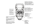
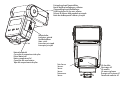
MECABLITZ 44 MZ-2
Bedienungsanleitung
Gebruiksaanwijzing
Manuale istruzioni
Mode d’emploi
Operating instruction
Manual de instrucciones
1.
2.
ķ
3.
3.1
3.2
3.3
3.4
3.5
3.6
3.6.1
3.6.2
3.7
3.8
4.
4.1
4.2
4.3
5.
5.1
5.1.1
5.1.2
5.2
5.2.1
5.3
5.3.1
5.3.2
6.
6.1
6.1.1
6.1.2
6.1.3
6.2
6.2.1
6.2.2
6.3
6.3.1
6.3.2
6.4
68
ķ
Safety instructions . . . . . . . . . . . . . . . . . . . . . . . . . . . . . . . . . . .69
Overview of the flash functions . . . . . . . . . . . . . . . . . . . . . . . . .70
Table 1: Overview of the flash functions . . . . . . . . . . . . . . . . . . .70
Preparing the mecablitz for use . . . . . . . . . . . . . . . . . . . . . . . . .71
Attaching the mecablitz to the camera . . . . . . . . . . . . . . . . . . . .71
Mounting the standard foot or SCA adapter . . . . . . . . . . . . . . . .71
Removing the standard foot or SCA adapter . . . . . . . . . . . . . . . .71
Mounting the mecablitz on the camera . . . . . . . . . . . . . . . . . . . .71
Removing the mecablitz from the camera . . . . . . . . . . . . . . . . . .71
Power supply . . . . . . . . . . . . . . . . . . . . . . . . . . . . . . . . . . . . . .71
Suitable batteries . . . . . . . . . . . . . . . . . . . . . . . . . . . . . . . . . . . .71
Replacing batteries . . . . . . . . . . . . . . . . . . . . . . . . . . . . . . . . . .71
Switching the flash unit on and off . . . . . . . . . . . . . . . . . . . . . . .72
Automatic switch-off function / Auto-OFF . . . . . . . . . . . . . . . . . .72
Operating concept . . . . . . . . . . . . . . . . . . . . . . . . . . . . . . . . . .72
Selecting and setting the flash modes TTL / A / M . . . . . . . . . . . .72
Selecting and setting the flash parameters . . . . . . . . . . . . . . . . . .72
Selecting and setting special functions . . . . . . . . . . . . . . . . . . . . .73
Operating modes of the mecablitz . . . . . . . . . . . . . . . . . . . . . . .73
TTL flash mode . . . . . . . . . . . . . . . . . . . . . . . . . . . . . . . . . . . . .73
Automatic fill-in flash in daylight . . . . . . . . . . . . . . . . . . . . . . . . .74
Matrix controlled TTL fill-in flash with Nikon cameras . . . . . . . . . .74
Automatic flash mode . . . . . . . . . . . . . . . . . . . . . . . . . . . . . . . .74
Fill-in flash in automatic mode . . . . . . . . . . . . . . . . . . . . . . . . . .75
Manual flash mode . . . . . . . . . . . . . . . . . . . . . . . . . . . . . . . . . .75
Manual flash mode M with full light output . . . . . . . . . . . . . . . . .76
Manual flash mode M with a partial light output “P” . . . . . . . . . .76
Flash parameters of the mecablitz . . . . . . . . . . . . . . . . . . . . . . .76
Zoom position of the reflector . . . . . . . . . . . . . . . . . . . . . . . . . . .76
Auto Zoom . . . . . . . . . . . . . . . . . . . . . . . . . . . . . . . . . . . . . . . .76
Manual zoom adaptation . . . . . . . . . . . . . . . . . . . . . . . . . . . . . .76
Manual change of the reflector’s zoom position with auto zoom . .77
Aperture . . . . . . . . . . . . . . . . . . . . . . . . . . . . . . . . . . . . . . . . . .77
Automatic aperture adaptation . . . . . . . . . . . . . . . . . . . . . . . . . .77
Manual aperture adaptation . . . . . . . . . . . . . . . . . . . . . . . . . . .77
ISO film speed . . . . . . . . . . . . . . . . . . . . . . . . . . . . . . . . . . . . .78
Automatic adaptation of the ISO film speed . . . . . . . . . . . . . . . . .78
Manual adaptation of the ISO film speed . . . . . . . . . . . . . . . . . . . .78
Manual flash exposure correction . . . . . . . . . . . . . . . . . . . . . . . .78
6.4.1 Manual flash exposure correction in TTL flash mode . . . . . . . . . . .78
6.4.2 Manual flash exposure correction in automatic flash mode A . . . .78
6.4.3 Setting procedure . . . . . . . . . . . . . . . . . . . . . . . . . . . . . . . . . . .78
6.4.4 Cancelling the correction value . . . . . . . . . . . . . . . . . . . . . . . . . .79
6.5 Setting a manual partial light output . . . . . . . . . . . . . . . . . . . . . .79
7.
Special functions of the mecablitz . . . . . . . . . . . . . . . . . . . . . . .79
7.1 Automatic switch-off function . . . . . . . . . . . . . . . . . . . . . . . . . . .79
7.2 Flash synchronisation . . . . . . . . . . . . . . . . . . . . . . . . . . . . . . . . .79
7.2.1 Normal synchronisation . . . . . . . . . . . . . . . . . . . . . . . . . . . . . . .79
7.2.2 2nd curtain synchronisation (REAR mode) . . . . . . . . . . . . . . . . . .80
7.2.3 Slow synchronisation / SLOW . . . . . . . . . . . . . . . . . . . . . . . . . .80
7.3 Extended zoom mode . . . . . . . . . . . . . . . . . . . . . . . . . . . . . . . .80
8.
Flash readiness indication . . . . . . . . . . . . . . . . . . . . . . . . . . . . .81
9.
Correct exposure confirmation . . . . . . . . . . . . . . . . . . . . . . . . .81
10. LC display of the mecablitz . . . . . . . . . . . . . . . . . . . . . . . . . . . .82
10.1 Maximum flash range indication . . . . . . . . . . . . . . . . . . . . . . . .82
10.1.1Automatic adaptation of maximum flash range indication . . . . . .82
10.1.2Manual adaptation of maximum flash range indication . . . . . . . .82
10.1.3Maximum flash range indication in the TTL and automatic flash mode A .82
10.1.4Maximum flash range indication in the manual flash mode M . . . .82
10.1.5Exceeding the capacity of maximum flash range indication . . . . . .83
10.1.6Blanking out the maximum flash range indication . . . . . . . . . . . .83
10.1.7Changing from meter to feet (m - ft) . . . . . . . . . . . . . . . . . . . . . .83
10.2 LC display illumination . . . . . . . . . . . . . . . . . . . . . . . . . . . . . . . .83
11. AF measuring beam . . . . . . . . . . . . . . . . . . . . . . . . . . . . . . . . .83
12. Flash techniques . . . . . . . . . . . . . . . . . . . . . . . . . . . . . . . . . . . .84
12.1 Bounce flash . . . . . . . . . . . . . . . . . . . . . . . . . . . . . . . . . . . . . . .84
12.2 Close-ups / macrophotography . . . . . . . . . . . . . . . . . . . . . . . . .84
13. Returning to the basic setting of the mecablitz . . . . . . . . . . . . . .84
14. Slave mode in the cordless Metz Remote System . . . . . . . . . . . .84
14.1 Activating the slave mode in the cordless Metz Remote System . . .84
14.2 Deactivating the slave mode . . . . . . . . . . . . . . . . . . . . . . . . . . . .85
15. Optional extras . . . . . . . . . . . . . . . . . . . . . . . . . . . . . . . . . . . .85
16. Troubleshooting . . . . . . . . . . . . . . . . . . . . . . . . . . . . . . . . . . . .86
17. Maintenance and care . . . . . . . . . . . . . . . . . . . . . . . . . . . . . . .86
18. Technical data . . . . . . . . . . . . . . . . . . . . . . . . . . . . . . . . . . . . . .86
Guide number table for TTL and full light output M in the metric system .132
Guide number table for partial light output MLo in the imperial system .133
Foreword
We congratulate you on purchasing this flash unit and thank you for your
confidence in Metz products.
It is only natural that you should want to use your flash unit right away.
However, we recommend that you study these Operating Instructions beforehand to be able to fully exploit and utilize all the capabilities offered.
This flash unit is compatible with:
• all cameras featuring a hot shoe contact.
• all cameras that have an accessory shoe without hot shoe contact and use
a sync cable (see Optional Extras).
• system cameras.
Optimal adaptation to your camera is achieved by using an adapter of the
SCA 3002 or SCA 300 system. The enclosed SCA Table will indicate the
adapter you require for your particular camera. This table also indicates the
special flash functions that can then be performed.
☞ Please also open the back cover page with the illustrations.
1. Safety instructions
• The flash unit is exclusively intended and approved for photographic
use!
• Never fire a flash in the vicinity of flammable gases or liquids (petrol,
solvents, etc.)! DANGER OF EXPLOSION!
• Never take flash shots of car, bus or train drivers, or of motorcycle and
bicycle riders, whilst they are travelling. They could be blinded by the
light and cause an accident!
• Never fire a flash in the immediate vicinity of the eyes! Flash fired directly in front of the eyes of a person or animal can damage the retina and
lead to severe visual disorders - even blindness!
• Only use the approved power sources listed in the Operating Instructions!
• Do not expose batteries to excessive heat, sunshine, fire and the like!
• Never throw exhausted batteries on to a fire!
• Exhausted batteries should be immediately removed from the flash unit.
Lye leaking out of spent batteries will damage the unit.
• Never recharge dry-cell batteries!
• Do not expose the flash unit or battery charger to dripping or splashing
water!
• Protect the flash unit from excessive heat and humidity. Do not store the
flash unit in the glove compartment of a car!
• Never place material that is impervious to light in front of, or directly on,
the reflector screen. The reflector screen must be perfectly clean when a
flash is fired. The high energy of the flash light will burn the material or
damage the reflector screen if this is not observed.
• Do not touch the reflector screen after a series of flash shots. Danger of
burns!
• Never disassemble the flashgun! DANGER: HIGH VOLTAGE. There are no
components inside the flashgun that can be repaired by a layman.
• When taking a series of flash shots at full light output and fast recycling
times as provided by NiCad battery operation, make sure to observe an
interval of at least 10 minutes after 15 flashes, otherwise the flash unit
will be overloaded.
• The mecablitz may only be used in combination with a camera-integrated flash unit if the latter can completely be folded out.
• Quick changes in temperature may cause condensation. Therefore give
the flashgun time to acclimatize!
69
ķ
Table 1: Overview of the flash functions
70
• = Flash function is supported by the mecablitz.
x = Flash function in only supported by the mecablitz if this function is set on the camera.
∆ = Only with Minolta digital cameras Dimage 5, 7, 7i
•
x
•
•
•
x
•
•
•
•
•
SCA 3002-Adapter
SCA 300-Adapter
SCA 301
•
•
•
•
•
•
•
•
•
•
•
•
•
•
•
•
•
•
•
•
•
•
•
•
•
∆
TTL flash mode
Automatic TTL fill-in flash
Manual TTL flash exposure correction
Auto flash mode
Man. flash exposure corr. in the auto flash mode
Manual flash mode
Man. flash mode with part. light output levels
Slave mode in Metz cordless remote system
Automatic motor zoom control of the reflector
Extended-zoom mode of the reflector
Automatic aperture setting
Automatic ISO setting
Autom. adaptation of the max. flash range indication
AF measuring beam control
Flash-ready indication in camera viewfinder
Corr. expos. confirmation in camera viewfinder
Automatic flash sync speed control
1st or 2nd curtain synchronisation (REAR)
Automatic switch-off function of the mecablitz
Wake-up function
Triggering control (Minolta, Pentax)
Spot beam mode (Pentax)
Contrast control (Pentax)
Preflash for red-eye reduction (Nikon)
Matrix controlled TTL fill-in flash (N ikon)
Minolta ADI flash control
SCA adapter
•
•
x
•
•
•
•
ķ
Flash functions
2. Overview of the flash functions
Various flash functions are available when the mecablitz 44 MZ-2 is operated
with an SCA adapter of the SCA 3002 or SCA 300 system or the standard
foot 301. The availability of the individual flash functions, however, depends
on the given camera system (camera manufacturer), the specific camera type
and the SCA adapter. For more detailed information please refer to the SCA
Table and the operating instructions for the individual SCA adapters.
3. Preparing the mecablitz for use
3.1 Attaching the mecablitz to the camera
☞ Before mounting or removing the flash unit, switch off both the camera and the mecablitz by their main switch.
The mecablitz can only be mounted on the camera with the standard foot
301 or an adapter of the SCA 300/SCA 3002 system (optional extra).
As standard, the mecablitz is fitted with the SCA 301 foot for simple flash
synchronisation. The shutter speed must be the same or slower than the flash
sync speed.
The “Set” version is supplied with the corresponding SCA adapter in place of
the standard foot 301.
3.2 Mounting the standard foot or SCA adapter
☞ Switch off the mecablitz by its main switch before mounting or removing the standard foot or SCA adapter!
• Hold the cover plate in the middle and withdraw (only when using the SCA
3002 adapter).
• Push the SCA adapter or the standard foot 301 all the way in.
3.3 Removing the standard foot or SCA adapter
☞ Switch off the mecablitz by its main switch.
• Use your fingernail to press up the locking lever in the middle of the mecablitz side and hold it depressed (when using an SCA 3002 adapter you
must first open the flap on the rear of the adapter) and, ...
• at the same time, withdraw the SCA adapter or standard foot backward.
3.4 Mounting the mecablitz on the camera
☞ Switch off the camera and the mecablitz by their main switch prior to
mounting.
• Turn the locking nut of the SCA adapter or standard foot 301 against the
mecablitz housing until the stop point is reached.
• Slide the mecablitz foot completely into the camera’s accessory shoe and
lock into position with the locking nut.
3.5 Removing the mecablitz from the camera
☞ Switch off the camera and the mecablitz by their main switch prior to
removal.
• Turn the locking nut of the SCA adapter or standard foot 301 against the
mecablitz housing until the stop point is reached.
• Withdraw the mecablitz with its foot backward from the camera’s accessory shoe.
3.6 Power supply
3.6.1 Suitable batteries
The mecablitz can be operated with any of the following batteries:
• 4 NiCad batteries, type IEC KR 15/51 (KR6, size AA). They permit very
fast recycling and are economical in use because they are rechargeable.
• 4 nickel-metal-hydride batteries, type IEC HR6 (size AA). They have a significantly higher capacity than NiCad batteries and are less harmful to the
environment (no cadmium).
• 4 alkaline-manganese dry-cell batteries, type IEC LR6 (size AA/AM3).
Maintenance-free power source for moderate power requirements.
• 4 lithium batteries, type IEC FR6 L91 (size AA). Maintenance-free highcapacity power source with a low self-discharge rate.
☞ Remove the batteries from the mecablitz if the flash unit is not going
to be used for an extended period of time.
3.6.2 Replacing batteries (Fig. 1)
The batteries are exhausted if the recycling time (elapsing from the triggering
of a full-power flash, e.g. in the M mode, to the moment the flash-ready indicator lights up again) exceeds 60 seconds.
• Switch off the mecablitz by its main switch.
• Slide the battery compartment cover in the direction of the arrow and fold open.
71
ķ
• Insert the batteries lengthwise in conformity with the indicated battery symbols and close the battery compartment cover.
☞ When loading batteries ensure correct polarity as indicated by the
symbols in the battery compartment. Mixed up battery poles may
destroy the flash unit.
Replace all batteries at a time and make sure that the batteries are of
the same brand and type and have the same capacity.
Exhausted batteries must not be thrown in the dustbin! Help protect
the environment and dispose of exhausted batteries at the appropriate collecting points.
3.7 Switching the flash unit on and off
The flash unit is switched on with the main switch on the battery compartment
cover. In the upper “On” position, the mecablitz is on.
To turn off the flash unit push the main switch down to its bottom position.
☞ If your mecablitz is not going to be used for an extended period of
time, we recommend to switch it off by its main switch and to remove
the power sources (batteries).
ķ 3.8 Automatic switch-off function / Auto - OFF (Fig. 2)
To save battery power and prevent inadvertent battery discharge, the mecablitz is factory-set to automatically switch to standby mode (Auto-OFF), while
the flash-ready light and the indications on the LC display are extinguished,
approx. 3 minutes after:
• switch-on
• triggering a flash
• touching the shutter release (only with adapters of the SCA 3002 system)
• switching off the camera’s exposure metering system (only with SCA 3002
system adapters).
After automatic switch-off the last-used settings are retained and instantly
available when the flash unit is switched on again. The flash unit is reactivated merely by depressing the “Mode” or “Zoom” keys or by touching the
camera’s shutter release (wake-up function).
72
☞ The mecablitz should always be turned off by its main switch if it is
not going to be used for an extended period of time.
The Auto-OFF function can be deactivated whenever required. See Chapter 7.1.
4. Operating concept
4.1 Selecting and setting the flash modes TTL / A / M
The individual flash modes TTL, Auto Mode A oder Manual Mode M are
selected with the Mode key. Press the Mode key repeatedly until the desired
operating mode is indicated by the corresponding flashing symbol. The setting becomes immediately effective. After about 5 seconds the operating
mode symbol stops flashing and is continuously lit.
☞ The individual flash modes of the mecablitz are explained in Chapter 5.
4.2 Selecting and setting the flash parameters
Continue depressing the preselect key
until the flash parameters to be
set (zoom, aperture, manual flash exposure correction EV, manual partial
light output P and ISO) start to flash on the LC panel.
Use the “+” and “-” keys to set the given flash parameter while the display is
flashing.
The setting is immediately taken over by the mecablitz.
After approx. 5 sec. the given symbol or flash parameter will be displayed
continuously (without flashing).
☞ When an adapter of the SCA 3002 system and a camera that transmits the data for the necessary flash parameters are used, then these
data will be automatically set on the mecablitz. It may happen that,
for instance, the aperture and ISO value are not displayed or cannot
be changed. This is not a malfunction. It merely means that the corresponding parameters are exclusively determined by the camera settings.
Not all the aforementioned flash parameters can be selected or set, depending on the chosen flash mode (TTL / A / M) or SCA adapter used.
☞ The settings for the individual flash parameters are explained in Chapter 6.
4.3 Selecting and setting special functions
Additional special functions can be selected in each flash mode with the
Select key.
Continue depressing the Select key to set, for example, Auto-OFF (automatic
switch-off), Extended Zoom Ex or other special functions (such as REAR, 2nd
curtain synchronisation), depending on the SCA adapter or camera system.
After a special function has been selected the icon of the given function and
the functional status (On or OFF) flash on the LC display.
While the display is flashing, you can modify the functional status with the
“+” and “-” keys, for activation or deactivation of the special function.
The setting is immediately taken over by the mecablitz.
The LC display returns to its normal state after approx. 5 sec.
☞ For the special flash functions please refer to Chapter 7 of the SCA
adapter manual.
5. Operating modes of the mecablitz
☞ The camera’s shutter speed must always be set to its flash sync speed
(see operating instructions for the camera) or a slower speed. If the
mecablitz is equipped with an SCA adapter, the shutter speed automatically switches or is reduced to flash sync speed, depending on the
camera model and the selected camera mode (see operating instructions for the individual SCA adapter and camera).
5.1 TTL flash mode (Fig. 3)
☞ The mecablitz must be fitted with a suitable SCA adapter for TTL flash
mode. TTL flash mode is only possible with cameras supporting this
mode! The standard foot 301 (only hot-shoe contact or sync cord
socket) does not permit TTL flash mode. If the mecablitz is used in conjunction with a camera or SCA adapter or the standard foot 301 that
do not support the TTL function, then uncontrolled full-power flashes
will be fired when the shutter release is pressed!
The TTL function can only be tested if a film has been loaded in the camera!
The TTL flash mode is a very simple way to achieve excellent flash shots. In
this mode exposure readings are taken by a sensor built into the camera
which measures the light reaching the film through the camera lens (TTL). The
electronic control circuit within the camera transmits a stop signal to the mecablitz as soon as the film has been exposed by the correct amount of light,
thereby instantly interrupting the flash. The advantage of this flash mode is
that all factors influencing correct exposure of the film (filters, change of aperture and focal length with zoom lenses, extensions for close-ups, etc.) are
automatically taken into account. You need not worry about setting the flash,
the camera’s electronic system automatically determines the correct amount of
flash light required. For the maximum flash range please observe the distances given in the LC display of the mecablitz (see Chapter 10.1). If flash exposure was correct, the LC display of the mecablitz indicates “o.k.” for about
3 sec. (see Chapter 9).
Normally, the TTL flash mode is supported by all camera modes (e.g. Program “P” (Full Auto Mode or “Green Square”), Aperture Priority Mode (“A”
or “Av”), Shutter Priority Mode (“T”, “Tv” or “S”), picture modes (landscape,
portrait, sports, etc.), Manual Mode “M”, etc.
☞ When selecting a film please check whether there are any limits given
regarding the maximum film speed or ISO value (e.g. max. ISO 1000)
for your camera when in TTL mode (please refer to the operating instructions for the camera).
Setting procedure for TTL mode
• Switch on the mecablitz by its main switch.
• Continue depressing the Mode key until TTL flashes on the LC display.
• The setting becomes immediately effective. The LC display returns to its normal state after approx. 5 sec.
☞ If an adapter of the SCA 3002 system is used, the TTL flash mode will
be activated on various camera models when in Program P, Full Auto
Mode, “Green Square”, or a picture mode (see operating instructions
for the SCA adapter).
73
ķ
5.1.1 Automatic fill-in flash in daylight (Fig. 4 and 5)
Most camera models automatically activate the fill-in flash mode in daylight
when in Full Auto Mode, Program P, “Green Square”, or the picture modes
(see operating instructions for the given camera).
Fill-in flash overcomes troublesome dense shadows and produces a more
balanced exposure between subject and background with contre-jour shots.
The camera’s computer-controlled metering system sets the most suitable
combination of shutter speed, working aperture and flash output.
☞ Ensure that the contre-jour light source does not shine directly into the
lens as this will mislead the camera’s TTL metering system!
In this instance there is no setting or display on the mecablitz for automatic
TTL fill-in flash.
5.1.2 Matrix controlled TTL fill-in flash with Nikon cameras
☞ This mode can only be selected and performed with a suitable Nikon
camera in combination with the SCA 3402 adapter.
ķ
Various Nikon cameras support the matrix controlled fill-in flash mode (see operating instructions for the given camera). In this flash mode subject and background
lighting are automatically balanced without overexposing the subject. The camera
establishes the exposure setting for the ambient light by matrix metering.
This fill-in flash mode is set and displayed either on the flash unit or on the
camera and depends on the camera model (please refer to the operating
instructions for your camera).
With cameras that do not provide transmission of any digital data to the mecablitz, this fill-in flash mode is set on the camera, or automatically activated by
the camera (see operating instructions for the given camera and SCA adapter).
There is no such setting made or indication given on the mecablitz.
Setting procedure for matrix controlled TTL fill-in flash mode on the mecablitz:
• Switch on the mecablitz by its main switch.
• Lightly touch the camera’s shutter release for data exchange between flash
unit and camera.
74
• Continue depressing the “Mode” key until “TTL” flashes on the LC display.
• Press the “+” key while “TTL” is flashing to activate the fill-in flash mode. This
causes the symbol
for this flash mode to be indicated on the LC display.
• The setting becomes immediately effective. The LC display returns to its normal state after approx. 5 sec.
Deactivating the matrix controlled TTL fill-in flash mode on the mecablitz:
• Switch on the mecablitz by its main switch.
• Lightly touch the camera’s shutter release for data exchange between flash
unit and camera.
• Continue pressing the “Mode” key until “TTL” and
flash on the LC display.
• Press the “-” key while “TTL” is flashing to deactivate the fill-in flash mode.
This causes the symbol
for this flash mode to be extinguished on the
LC display.
• The setting becomes immediately effective. The LC display returns to its normal state after approx. 5 sec.
5.2 Automatic flash mode
In the auto flash mode a sensor built into the mecablitz measures the light
reflected off the subject. The flash is cut off as soon as sufficient light has
been emitted for correct exposure. This eliminates the need to recalculate and
reset the aperture each time the distance is changed, provided that the subject remains within the indicated maximum flash range.
The sensor of the mecablitz must be directed at the subject, regardless of the
direction in which the reflector is pointing. The sensor has a coverage of 25°,
and only measures the light for the time a flash is fired by the mecablitz. The
“ok” display on the mecablitz lights up for approx. 3 sec. when flash exposure was correct (see Chapter 9).
The automatic flash mode is possible with an adapter of the SCA 300 or
SCA 3002 system and with the standard foot 301.
☞ Some cameras will not support the mecablitz in automatic flash mode
5.2.1 Fill-in flash in automatic mode
Set the aperture priority mode (“A” or “Av”) or the manual mode “M” on the
camera. Then select a suitable aperture and shutter speed (for mode “M”) for
the existing shooting situation (see operating instructions for the camera).
If your mecablitz is equipped with an SCA 3002 system adapter and your
camera automatically transmits the f-stop to the flash unit, then the mecablitz
can also be used in the camera modes Program P, Full Auto Mode, “Green
Square” and the picture modes, or in the Shutter Priority Modes “Tv”, “T”, or
“S” (see operating instructions for the given SCA adapter).
Setting procedure for automatic flash mode
• Equip the mecablitz with an SCA adapter or standard foot 301 and mount
on the camera.
• Adjust the camera as described in its operating manual.
• Switch on the mecablitz with the main switch.
• Press the Mode key repeatedly until A flashes on the display.
• The setting becomes immediately effective. The LC display returns to its normal state after approx. 5 sec.
☞ The subject should be located within about 40 % to 70 % of the maximum
distance range indicated on the mecablitz LC display (see Chapter 10.1).
This gives the electronic system sufficient leeway for compensation.
Caution with zoom lenses! Depending on their design, zoom lenses can
cause a loss of light in the order of up to one f-stop. Moreover, the effective aperture may vary with the focal length settings. This can be compensated by correcting manually the aperture or by manual flash exposure correction.
The two established values for aperture and shutter speed can be set on the
camera because the camera’s shutter speed is slower than the camera’s flash
sync speed.
To obtain a balanced fill-in light, for instance in order to retain the character
of the shadows, it is advisable to select on the flashgun a manual correction
value of -1 EV (f-stop) to -1.7 EV (see Chapter 6.4.3).
☞ Ensure that the contre-jour light source does not shine directly into the
sensor of the mecablitz as this will mislead the metering system of the
mecablitz.
when an SCA adapter is used (see operating instructions for the given
camera and SCA adapter). In this case the mecablitz should be fitted
with the 301 standard foot.
Use the camera’s or a hand-held exposure meter to establish the required
aperture and shutter speed for a normal exposure. If possible take a meter
reading of the subject’s background separately from the actual subject.
Ensure that the camera’s shutter speed either equals or is slower than the
fastest flash sync speed (see operating instructions for the given camera).
Example:
Established aperture = f/8
Established shutter speed = 1/60th sec.
Flash sync speed of the camera e.g. 1/100th sec. (see operating instructions
for the given camera).
5.3 Manual flash mode
☞ If the mecablitz is equipped with an SCA 3002 system adapter, some
cameras automatically change the mecablitz to TTL flash mode when
in Program “P”, Full Auto Mode, “Green Square” or a picture mode.
Manual flash mode is then no longer possible. If necessary attach the
standard foot 301 to the mecablitz for manual flash operation.
There is no correct exposure confirmation on the mecablitz LC display when
in manual flash mode.
Set an aperture priority mode (“A” or “Av”) or manual mode “M” on the
camera. Select an aperture and shutter speed (with “M”) on the camera to
75
ķ
match the given photographic situation (see the camera’s operating instructions).
Setting procedure for the manual flash mode M
• Switch on the mecablitz by its main switch.
• Depress the Mode key repeatedly until M and the manual partial light output level P (1/1 for full light output in our example) flash on the LC display.
• The setting becomes immediately effective. The LC display returns to its normal state after approx. 5 sec.
☞ The LC display of the mecablitz indicates the selected manual partial
light output in place of the f-stop.
5.3.1 Manual flash mode M with full light output
In this mode the mecablitz always fires uncontrolled flashes at full light output
(P 1/1). Adaptation to the given photographic situation is only by setting the
aperture on the camera accordingly. The mecablitz LC display will indicate
the flash-to-subject distance required for a correct flash exposure (see also
Chapter 10.1).
ķ 5.3.2 Manual flash mode M with a partial light output “P”
If necessary the manual light output of the mecablitz can be reduced. For this
purpose you can set a partial light output “P” on the mecablitz. For more
details please refer to Chapter 6.5.
6. Flash parameters of the mecablitz
For the mecablitz to work correctly it is necessary to adapt different flash
parameters such as zoom position of the reflector, aperture and ISO film
speed to the settings on the camera.
With certain flash modes it is additionally possible to set manual flash exposure correction EV and manual partial light output P.
When the mecablitz is used in conjunction with an adapter of the SCA 3002
system, then diverse flash parameters such as zoom position, aperture and
ISO are automatically transmitted from the camera to the mecablitz where
76
they are set accordingly. For this purpose, the camera must support the corresponding ditital data exchange with the SCA adapter or the mecablitz. For
details please refer to the operating instructions for the given SCA adapter.
☞ When the mecablitz is used with an adapter of the SCA 300 system or
with the 301 standard foot, then the flash parameters must be set on
the mecablitz by hand.
6.1 Zoom position of the reflector
The setting of the zoom reflector can be adjusted to match focal lengths as of
28 mm of the lens in use (35 mm format). For lenses with focal lengths as of
20 mm a wide-angle diffuser (optional extra, see Chapter 14) can be used.
Possible zoom reflector settings:
28mm - 35mm - 50mm - 70mm - 85mm - 105mm.
6.1.1 Auto Zoom
If the mecablitz is fitted with an adapter of the SCA 3002 system and is used
with a camera that transmits lens focal length data to the flash unit, the zoom
reflector position of the mecablitz is automatically adjusted to the focal length
of the lens in use. The LC display of the mecablitz then indicates Auto Zoom
and the zoom reflector setting (mm).
☞ The automatic adjustment of the zoom reflector position commences
with focal lengths as of 28 mm. If a focal length of less than 28 mm is
used, “28” will flash on the LC display to warn you of vignetting because the flash unit’s illumination will not cover the full picture area.
6.1.2 Manual zoom adaptation
The zoom position of the reflector must be set manually when the mecablitz is
fitted with an SCA 300 system adapter or the 301 standard foot, and is used
with a camera that cannot transmit focal length data. In this particular case
M.Zoom is indicated on the display.
Setting procedure
• Continue depressing the preselect key
until the reflector position (mm)
flashes on the LC display.
• Use the “+” and “-” keys to set the required position of the zoom reflector
while the display is flashing. The setting is immediately taken over by the
mecablitz.
• After approx. 5 sec. the LC display switches back to its normal state.
• The choice of the zoom reflector position depends on the focal length of the
camera lens (35 mm format). The zoom reflector should be set to the focal
length of the lens in use or the next smaller value.
If you use a zoom lens and do not always need the full guide number and
maximum flash range of the mecablitz you can leave the zoom reflector at
the position for the shortest focal length of the zoom lens. This will provide
full light coverage of the picture and eliminate the need for permanent adaptation to the lens focal length.
Example:
A zoom lens with a focal length range of 35 mm to 105 mm is being used. In
this case set the zoom reflector to 35 mm.
• While this display flashes, continue depressing the “+” key until Auto Zoom
is indicated on the LC panel. Please note that the camera’s exposure system
must be activated for this purpose (e.g. by lightly touching the shutter release) so that a data exchange can take place.
• The setting is immediately taken over by the mecablitz.
• After approx. 5 sec. the display switches back to its normal state.
6.1.3 Manual change of the reflector’s zoom position with auto zoom
When the mecablitz is in the manual mode M the selected partial light output
will be indicated instead of the aperture.
The zoom position of the reflector can be changed when the mecablitz is
used with an SCA 3002 system adapter and a camera capable of data
transmission, to achieve special lighting effects (such as hot-spot, etc.):
See above to select the required zoom position.
After storage M.Zoom will be indicated on the display next to the zoom position (mm).
If the zoom position continues to flash on the LC display after automatic storage, then this is a warning that flash coverage will be incomplete with the
selected zoom position. In this case select a lower zoom position for the
mecablitz reflector.
Resetting to auto-zoom mode
• Continue depressing the preselect key
until the reflector position (mm)
flashes on the LC display.
6.2 Aperture
6.2.1 Automatic aperture adaptation
If the mecablitz is equipped with an adapter of the SCA 3002 system, and if a
camera is used that transmits the data for the set aperture to the flash unit, then
the aperture setting on the mecablitz is automatically adapted accordingly.
☞ With some cameras the aperture is not indicated on the mecablitz
display or the aperture cannot be changed (see operating instructions
for the given SCA adapter).
6.2.2 Manual aperture adaptation
The aperture of the mecablitz must be set manually when the mecablitz is
operated with an adapter of the SCA 300 system or the 301 standard foot in
conjunction with a camera that is incapable of transmitting aperture data.
Setting procedure
• Continue depressing the preselect key
until the aperture value flashes
on the LC display.
• While this display flashes, use the “+” and “-” keys to adjust the aperture
to the required f–stop. The setting is immediately taken over by the mecablitz.
• After approx. 5 sec. the LC display switches back to its normal state.
☞ The mecablitz must be adjusted to the f-stop set on the camera or
camera lens.
77
ķ
6.3 ISO film speed
6.3.1 Automatic adaptation of the ISO film speed
If the mecablitz is equipped with an adapter of the SCA 3002 system, and is
used in conjunction with a camera that is capable of transmitting ISO film
speed data to the flash unit, then the ISO speed on the mecablitz will automatically be adapted accordingly.
☞ With some camera models the ISO speed will not be indicated on the
mecablitz LC display or the ISO value cannot be changed (see operating instructions for the given SCA adapter).
6.3.2 Manual adaptation of the ISO film speed
ķ
The ISO speed must be set manually on the mecablitz when the mecablitz is
used in conjunction with an SCA 300 system adapter or with the 301 standard foot, or if the camera cannot transmit ISO film speed data.
Setting procedure
• Continue depressing the preselect key
until the ISO value flashes on
the LC display.
• While this value flashes, use the “+” and “-” keys to modify the ISO speed
as required. This setting is immediately taken over by the mecablitz.
• After approx. 5 sec. the display switches back to its normal state.
☞ The mecablitz must be adjusted to the ISO value set on the camera.
Observe the ISO speed of the film loaded in the camera.
☞ A dark subject in front of a bright : Positive correction value (approx.
1 to 2 f-stops). A light subject in front of a dark background: Negative
correction value (approx. -1 to -2 f–stops). If a correction value is set
the maximum flash range indicated on the mecablitz LC display may
change to match the given correction value (depending on the SCA
adapter and camera model).
Do not forget to cancel manual flash exposure correction after picture shooting.
6.4.1 Manual flash exposure correction in TTL flash mode
The mecablitz must be fitted with an SCA 3002 system adapter and the TTL
flash mode must be selected on the mecablitz.
The camera must support the setting of a manual correction value on the
mecablitz. With some cameras a manual correction value for TTL flash exposure can only be set on the camera body. In such an event, a corresponding
setting cannot be made on the mecablitz or remains ineffective (see operating instructions for the given SCA adapter and camera).
☞ Exposure correction by changing the lens aperture is not possible
because the camera’s automatic exposure system will regard the
changed aperture as a normal working aperture.
6.4.2 Manual flash exposure correction in automatic flash mode A
The mecablitz must be fitted with an SCA adapter or the 301 standard foot.
The automatic flash mode A must be set on the mecablitz.
6.4 Manual flash exposure correction
6.4.3 Setting procedure
The automatic TTL flash expossure system of most cameras is matched to a
25 % degree of light reflection by the subject (average amount of light reflected by subjects shot with flash). Consequently, a dark background that absorbs a great deal of light, or a bright background that reflects a great deal
of light, can result in under- or overexposure, respectively.
To offset this effect a manual correction value can be set to adapt the automatic flash exposure to the photographic situation. The correction value
depends on the contrast prevailing between subject and background.
• Set the TTL flash mode or the automatic flash mode A on the mecablitz.
• Continue depressing the preselect key
on the mecablitz until EV and
the correction value (instead of the f-stop) flash on the display.
• While the corresponding displays are flashing, use the “+” and “-” keys to set
the required correction value (in this example the correction value = -0.7 f-stop).
• The setting becomes immediately effective.
78
• The display changes after approx. 5 sec.: The displayed correction value is
replaced by the aperture. EV will flash on the display to indicate that a correct value has been set.
6.4.4 Cancelling the correction value
• Continue depressing the preselect key
on the mecablitz until EV and
the correction value (instead of the f-stop) flash on the display.
• While the corresponding displays are flashing set the 0.0 correction value
with the “+” and “-” keys.
• The setting becomes immediately effective.
• The display changes after approx. 5 sec.: The aperture will then be displayed instead of the correction value. The reference to an EV correction
value is no longer indicated by the LC display.
6.5 Setting a manual partial light output
In this mode the flash unit always fires an uncontrolled flash with part of the
full light output. Adaptation to the given photographic situation is by selecting a partial light output and a corresponding aperture setting on the camera. The LC display of the mecablitz will indicate the flash–to–subject distance required for a correct flash exposure (also see Chapter 10.1.4).
Setting procedure
• Switch on the mecablitz by its main switch.
• Continue depressing the preselection key
until P and the partial light
output flash on the LC display.
• While the display is flashing, use the “+” and “-” keys to set the value for
the desired partial light output (in our example P 1/8).
• The setting becomes immediately effective.
• After about 5 sec. the partial light output is continuously displayed (without
flashing).
☞ The LC display of the mecablitz indicates the selected manual partial
light output in place of the f-stop.
7. Special functions of the mecablitz
7.1 Automatic switch-off function
Switching off the automatic switch-off function
• Switch on the mecablitz by its main switch.
• Continue depressing the Select key until the mecablitz display indicates 3m
(for 3 minutes).
• Continue depressing the “-” key until OFF flashes on the LC display of the
mecablitz.
• The setting becomes immediately effective. The LC display returns to its normal state after approx. 5 sec.
Switching on the automatic switch-off function
• Switch on the mecablitz by its main switch.
• Continue depressing the Select key until the mecablitz display indicates 3m
(for 3 minutes).
• Continue depressing the “+” key until On flashes on the LC display of the
mecablitz.
• The setting becomes immediately effective. The LC display returns to its normal state after approx. 5 sec.
7.2 Flash synchronisation
7.2.1 Normal synchronisation (Fig. 6)
☞ Possible with SCA adapter and standard foot 301.
In normal synchronisation the mecablitz is triggered at the beginning of the
exposure time (1st curtain synchronisation). Normal synchronisation is the
standard mode on all cameras, and is suitable for most flash shots. Depending upon the given mode, the camera is changed over to flash sync speed
(only with a suitable SCA adapter; optional extra), the customary ones
being between 1/30th sec. and 1/125th sec. (see camera’s operating instructions). No settings have to be made on the mecablitz, nor is there any
display for this mode.
79
ķ
7.2.2 2nd curtain synchronisation (REAR mode) (Fig. 7)
☞
Only possible with a suitable SCA adapter and a suitable camera!
Various cameras offer the facility of second-curtain synchronisation (REAR
mode) triggering the mecablitz by the end of the exposure time. Second-curtain synchronisation is particularly advantageous when using slow shutter
speeds (slower than 1/30 s) or when shooting moving objects that have their
own source of light. Second-curtain synchronisation gives a more realistic
impression of movement because the light streaks behind the light source
instead of building up in front of it, as is the case when the flash is synchronised with the 1st shutter curtain.
Depending on its operating mode and the SCA adapter, the camera uses
shutter speeds slower than its sync speed.
☞ Some camera types make it necessary to activate the REAR mode on
the camera. Setting the REAR mode on the mecablitz will then be impossible or ineffective. For more details please refer to the operating
instructions for the SCA adapter or the camera.
ķ
Switching on the REAR mode
• Continue depressing the Select key until REAR appears on the LC display.
• Continue depressing the “+” key until On flashes on the LC display.
• The setting becomes immediately effective. The LC display returns to its normal state after approx. 5 sec.
The “REAR” symbol for 2nd curtain synchronisation continues to be indicated
on the mecablitz LC display after it has been set.
☞ Always use a tripod to avoid camera shake with slow shutter speeds!
Do not forget to switch off this function after exposure, otherwise unintended slow shutter speeds will continue to be used for “normal”
flash shots.
Switching off the REAR mode
• Continue depressing the Select key until REAR appears on the LC display.
• Continue depressing the “-” key until OFF flashes on the LC display.
80
• The setting becomes immediately effective. The LC display returns to its normal state after approx. 5 sec.
The “REAR” symbol for 2nd curtain synchronisation is no longer indicated by
the mecablitz display.
The mecablitz is then once again synchronised with the first curtain (normal
synchronisation).
7.2.3 Slow synchronisation / SLOW
Various cameras feature slow flash synchronisation in certain modes. This
mode will give added prominence to the background at lower ambient light
levels. This is achieved by matching the shutter speeds to the ambient light.
Accordingly, shutter speeds that are slower than the camera’s sync speed are
automatically adjusted by the camera. Some cameras automatically activate
SLOW synchronisation in connection with certain camera programs (e.g.
night shots program). No settings are made on the mecablitz nor is there any
display for this mode.
☞ Use a tripod to avoid camera shake with slow shutter speeds!
7.3 Extended zoom mode
☞ The extended zoom mode is only supported with SCA adapters of the
SCA 3002 system. The camera must then transmit the focal length
data of the lens to the flash unit or the SCA adapter (see operating
instructions for the corresponding SCA adapter).
The extended zoom mode Ex reduces the reflector position of the mecablitz
by one step compared with the focal length of the camera lens. The resulting
wider light coverage inside rooms provides additional stray light (reflections)
to achieve softer flash illumination.
Example of extended zoom mode:
The focal length set on the camera lens is 35 mm. The extended zoom mode
sets a 28 mm reflector position on the mecablitz even though 35 mm continues to be indicated on the LC display!
The extended zoom mode is only possible in the “Auto Zoom” mode with a
focal length setting as of 35 mm (35 mm format). Since the start position of
the zoom reflector is 28 mm, a focal length of less than 35 mm will cause
“28” mm to flash on the LC display, thereby warning the user that the required 24 mm reflector position for extended zoom mode cannot be set.
☞ Shots with a 28 mm to 35 mm focal length of the lens will be correctly
illuminated right out to the image corners by the mecablitz also in the
extended zoom mode.
Switching on the extended zoom mode
• Continue depressing the Select key until “Ex” is indicated on the LC display.
• Continue depressing the “+” key until “On” flashes on the LC display.
• The setting becomes instantly effective. The LC display is switched back to
its normal state after approx. 5 sec.
After the setting procedure, the “Ex” symbol for extended zoom mode will
continue to be indicated on the mecablitz LC display.
☞ Please note that the wider illumination coverage in extended zoom
mode results in a diminished maximum flash range.
Switching off the extended zoom mode
• Continue depressing the Select key until “Ex” is indicated on the LC display.
• Continue depressing the “-” key until “OFF” flashes on the LC display.
• The setting becomes instantly effective. The LC display switches back to its
normal state after approx. 5 sec.
After storage in the memory, the “Ex” symbol for extended zoom mode will
no longer be indicated on the mecablitz LC display.
8. Flash readiness indication
The flash readiness symbol lights up on the mecablitz when the flash capacitor is charged, thereby indicating that flashes can be fired. If a picture is
shot before flash readiness is signalled, then the flash unit will not be triggered so that exposure may be incorrect.
☞ If the mecablitz is equipped with a suitable SCA adapter, flash readi-
ness will, depending on the camera type, automatically be transmitted
to the camera or will be indicated in the camera’s viewfinder and induce the camera to switch to its flash sync speed (please refer to the
operating instructions for the SCA adapter and the camera).
9. Correct exposure confirmation
The correct exposure confirmation “o.k.” is indicated for 3 sec. in the LC display if the picture was correctly exposed in the automatic (A) or TTL flash
mode. At the same time the LC display will automatically be illuminated.
This gives the user the opportunity to fire a test flash while in automatic flash
mode so that the correct aperture can be established beforehand. This is particularly valuable with bounce flash when reflection conditions are difficult to
judge.
The test flash can be triggered with the manual firing button . If the “o.k.”
exposure indicator remains dark after the test flash was fired, then set the
next lower f-number, or diminish the distance to the reflecting surface or subject, and repeat the test flash.
☞ When firing a test flash, hold the flash unit with the built-in sensor in
the same manner as for the later shot.
This facility can also be used with TTL mode without having to produce test
shots. The flash unit is set to automatic mode A, and the correct aperture is
then determined with a test flash in the previously described manner. The
established aperture is set on the camera and the flash unit is then readjusted
to TTL flash mode.
This procedure is relatively accurate with lenses of medium focal length of between 28 mm and 85 mm. However, in borderline cases, underexposure may
result in TTL flash mode. In such an event the ok exposure confirmation will not
be given after the shutter has been released. Select the next smaller f-number
(e.g. f/8 instead of f/11) and have another try.
81
ķ
☞ If the mecablitz is equipped with a suitable SCA adapter, a correct
exposure confirmation signal will, depending on the camera type,
automatically be transmitted to the camera for indication in the camera’s viewfinder (please refer to the operating instructions for the
SCA adapter and the camera).
10. LC display of the mecablitz
ķ
The LC display of the mecablitz serves to indicate the selected flash mode, the
flash parameters (zoom position, aperture, ISO film speed), maximum flash
range, manual partial light output and selected special functions.
The number of the displayed symbols depends on the selected flash mode,
the SCA adapter, the camera model and on the operating status. Consequently, some parameters will only be displayed during certain manual setting operations (e.g ISO).
☞ Depending upon the given camera model and SCA adapter, the information given in the LC display of your mecablitz may differ slightly
from the examples shown here. This is not a malfunction but rather
unavoidable on account of the adapting capabilities to so many different camera systems (manufacturers) and camera types.
10.1 Maximum flash range indication
10.1.1 Automatic adaptation of maximum flash range indication
☞ For automatic adaptation of the maximum flash range indication the
mecablitz must be fitted with an SCA 3002 system adapter. Furthermore, the camera must be able to transmit the necessary flash parameters (see below) to the SCA adapter or mecablitz (see the operating
instructions for the given SCA adapter and the camera). A data exchange must have taken place between camera and mecablitz (e.g.
by lightly touching the camera’s shutter release).
Various cameras transmit to the mecablitz the flash parameters for ISO film
speed, focal length of the lens (mm), aperture, and exposure correction. The
mecablitz will automatically adjust the necessary settings accordingly. It will
then calculate from the flash parameters and its guide number the maximum
82
range of the flash. This maximum flash range is indicated on the LC display
of the mecablitz.
10.1.2 Manual adaptation of maximum flash range indication
If the mecablitz is fitted with an SCA 300 system adapter or 301 standard
foot, or if the camera is incapable of transmitting the flash parameters, then
the values for the reflector’s zoom position, the ISO film speed and the f-stop
must be manually set on the mecablitz for a reliable maximum flash range
indication (see Chapter 6).
10.1.3 Maximum flash range indication in the TTL and automatic
flash mode A
The mecablitz LC display indicates the maximum flash range. The indicated
value relates to a factor of 25 % of light reflection by the subject, which applies to most photographic situations. Pronounced deviations from this reflection factor, e.g. highly reflective or poorly reflecting objects, can influence
the maximum flash range of the mecablitz.
Always observe the maximum flash range indicated by the mecablitz LC display. The subject should be within approx. 40 % to 70 % of the indicated
value. This gives the electronic system sufficient scope for compensation. To
avoid overexposure, the minimum flash-to-subject distance should not be less
than 10 % of the indicated value. Adaptation to the given photographic situation is possible by changing the aperture setting on the lens.
Example:
In the example on the left the maximum flash range extends from 0.6 m to
6.2 m. Ideally, the subject should be located within a distance range of
approx. 2.5 m and 4.3 m.
10.1.4 Maximum flash range indication in the manual flash mode M
The LC display of the mecablitz indicates the distance to be maintaned for correct flash exposure of the subject. Adaptation to the given photographic situation is achieved by changing the aperture setting on the lens and selecting either full light output or a partial light output level “P” (see Chapter 5.2.1).
Example:
In our example on the left the main subject should be at a distance of 6.2 m
from the mecablitz.
10.1.5 Exceeding the capacity of maximum flash range indication
The mecablitz can indicate a maximum range of 199 m or 199 ft. In the
event of high ISO values (e.g. ISO 6400) and large aperture openings the
display range may be exceeded. This will be signalled by an arrow or triangle after the indicated flash range.
10.1.6 Blanking out the maximum flash range indication
The mecablitz LC display does not indicate any distances when the flash
head is swivelled up or down out of its normal position.
10.1.7 Changing from meter to feet (m - ft)
The maximum flash range indicated by the mecablitz LC display can be either in meter (m) or feet (ft). To change between the two, proceed in the following manner:
• Switch off the mecablitz by its main switch.
• Keep the Select key depressed.
• Switch on the mecablitz by its main switch.
• Release the Select key.
• The display changes and indicates only ft (or m).
• Press the “+” or”-” key.
• The maximum flash range is now given in ft (or m).
10.2 LC display illumination
Pressing the Mode, Select “+”, “-” or preselect key will activate the illumination of the mecablitz LC display panel. The illumination will be extinguished
when a flash is fired. If the shot was correctly exposed in TTL or automatic
flash mode, then the LC display illumination will automatically be activated
for the time the “o.k.” signal is displayed.
☞ The settings on the mecablitz are not changed when the above keys
are pressed for the first time.
11. AF measuring beam
☞ The AF measuring beam of the mecablitz can only be activated by
autofocus cameras that support the flash unit’s AF measuring beam.
The mecablitz must be fitted with an SCA 3002 adapter!
The AF measuring beam is activated by the camera electronics when the
ambient lighting conditions are insufficient for automatic focusing. The AF
beam projects a striped pattern on to the subject, and the camera uses this
pattern to focus automatically. The AF beam has a range of approx. 6 m to
9 m (with a 50 mm/f/1.7 standard lens). Parallax error between lens and
AF red light emitter limits the close-up range of the AF measuring beam to
approx. 0.7 m - 1 m. Low-speed zoom lenses can significantly curtail the
range of the AF measuring beam.
☞ Various autofocus cameras only support their own built-in AF illuminator (please also refer to the operating instructions for the given camera). In such an instance the AF measuring beam of the mecablitz
will not be activated.
☞ Please note when selecting the camera’s autofocus mode that most
cameras only support the AF measuring beam in the operating mode
“Single AF” or “AF mode without continuous focusing”. The AF measuring beam will not be activated in the “Servo AF” or “continuous
auto focusing” modes (see operating instructions for the given
camera).
☞ Various cameras dispose of several AF sensors in their viewfinder.
However, the AF measuring beam of the mecablitz will only support the
camera’s central AF sensor. If your camera features several AF sensors
we recommend to activate only the camera’s central AF metering area
(please refer to the operating instructions for your camera).
If a decentral AF sensor is manually selected by the photographer, or automatically by the camera, the emitter of the AF measuring beam of the mecablitz will not be activated. In such a situation, some cameras will use their
own built-in AF illuminator instead of the AF measuring beam (see operating
instructions for the given camera).
83
ķ
12. Flash techniques
12.1 Bounce flash
ķ
Photos shot with full frontal flash are easily recognized by their harsh, dense
shadows. This is often associated with a sharp drop in light from the foreground to the background. This phenomenon can be avoided with bounce
flash because the diffused light will produce a soft and uniform rendition of
both the subject and the background. For this situation the reflector is turned
in such a manner that the flash is bounced off a suitable reflection surface
(e.g. ceiling or walls of a room).
The reflector can be turned vertically up to 90°. When turning the reflector
vertically, ensure that it is moved by a sufficiently wide angle so that direct
light can no longer fall on the subject. Consequently, always turn the flash
head at least to its 60° lock-in position. The distance readings on the LC
panel will disappear. The flash-to-subject distance via the ceiling or wall is
now an unknown magnitude.
The light bounced off the reflecting surfaces produces a soft and uniform illumination of the subject. The reflecting surface must be white or have a neutral colour, and it must not be structured e.g. by wooden beams in a ceiling,
as these might cast shadows. For colour effects just select the reflective surface in the desired colour.
☞ Please take into account that the maximum flash range is considerably diminished when bouncing the flash.
12.2 Close-ups / macrophotography
The reflector can be swivelled down by an angle of -7° to compensate for
parallax error. For this purpose depress the unlocking button of the reflector
and swivel down.
For close-ups it is necessary to ensure that certain minimum lighting distances
are maintained to avoid overexposure.
84
☞ The minimum lighting distance is approx. 10 per cent of the maximum
flash range indicated on the LC display. Since the maximum flash range
is not given in the LC display when the reflector is swivelled down, then
be guided by the maximum flash range indicated by the mecablitz when
the reflector is in its normal position.
13. Returning to the basic setting of the mecablitz
The mecablitz returns to its basic setting when the Mode key is kept depressed
for at least three seconds.
The following settings are adjusted:
• Activation of the Auto-Off function (3m On).
• Mode M.Zoom; reflector position 28 mm. If the mecablitz is operated with
an SCA adapter of the SCA 3002 system and if the camera transmits to
the mecablitz the focal length of the lens in use (e.g. when the shutter release is lightly touched), then Auto Zoom will be activated.
• The extended zoom mode is cancelled.
14. Slave mode in the cordless Metz Remote System
The mecablitz supports the slave mode in the cordless Metz Remote System.
For this purpose, the mecablitz must be fitted with an SCA 3083 digital or
SCA 3082 slave adapter (optional extra, see Chapter 14.2). A master flash
unit (controller) (only mecablitz 40 MZ-..., 50 MZ-5, 54 MZ-3, 70 MZ-...)
mounted on the camera controls one or more off-camera slaves in the TTL or
automatic flash mode A without any connecting cables.
14.1 Activating the slave mode in the cordless Metz Remote System
• Switch off the mecablitz by its main switch.
• Equip the mecablitz with an SCA 3083 digital or SCA 3082 slave adapter.
• Switch on the mecablitz. The TTL flash mode is automatically activated on
the flash unit. The display indicates SL and the remote channel Ad1. The
reflector of the mecablitz is automatically positioned on 28 mm. The AF
measuring beam flashes when the mecablitz is ready for firing. When in
slave mode, the mecablitz LC display will neither indicate the aperture nor
the distance.
☞ Please note that the mecablitz 44 MZ-2 as SLAVE will only support the
remote channel “Ad1” in the cordless Metz-Remote-System. For more
details about the slave mode please refer to the operating instructions
for the slave adapter.
14.2 Deactivating the slave mode
• Switch off the mecablitz by its main switch and remove the slave adapter.
• Equip the mecablitz with the SCA adapter or the standard foot 301.
• The slave mode is automatically cancelled when the mecablitz is switched
on again.
15. Optional extras
☞ No guarantee is given for malfunction and damage to the mecablitz
caused by the use of accessories from other manufacturers.
• SCA adapters of the SCA 300 system
for flash operation with system cameras. See separate operating instructions.
• SCA adapters of the SCA 3002 system
for flash operation with system cameras providing digital data transmission
of SCA functions. Extends the number of functions compared with the SCA
300 system. See separate operating instructions.
• Slave-Adapter SCA 3083 digital
(Item No. 000330838)
for cordless slave flash operation in three modes:
mecalux slave mode, mecalux slave mode with preflash suppression (for
digital cameras with monitoring preflash technology) and slave mode in
the cordless Metz TTL Remote System or Metz Automatic Remote System.
• Slave-Adapter SCA 3082
(Item No. 00033082A)
For cordless slave operation in the Metz TTL Remote-System or Metz-Automatic Remote System.
• Wide-angle diffuse
(Item No. 000044217)
To cover lens focal lengths as of 20 mm. The maximum flash range is reduced by a factor of approx. 1.4 due to the corresponding loss of light.
• Colour filter set 44-32
(Item No. 00004432A)
Consists of 4 colour filters to achieve special lighting effects, plus a clear filter to hold colour foils in any colour.
• Mecabounce 44-90
(Item No. 000044900)
A diffuser to achieve soft illumination in the simplest possible manner. The
effect is very impressive because the pictures are given a very soft atmosphere. Facial colours are rendered more naturally. However, loss of light
halves the maximum flash range.
• Bounce diffuser 54-23
(Item No. 000054236)
The soft directed light diminishes dense shadows.
85
ķ
16. Troubleshooting
18. Technical data
Should the LC display indicate meaningless information or should the flash
unit not work properly in the individual modes, then switch off the mecablitz
for about 10 seconds by its main switch. Check the camera settings and find
out if the flash unit’s foot is correctly mounted in the camera’s accessory shoe.
The mecablitz must operate properly when it is switched on again. Contact
your local dealer should this not be the case.
Max. guide number at ISO 100 / 21°; zoom 105 mm:
Metric system: 44 Imperial system (ft): 144
17. Maintenance and care
ķ
Remove any grime and dust with a soft, dry or silicon-treated cloth. Never
use detergents that could damage plastic parts.
Forming the flash capacitor
The flash capacitor incorporated in the flash unit undergoes a physical change
when the flash unit is not switched on for prolonged periods of time. For this
reason it is necessary to switch on the mecablitz for approx. 10 minutes every
3 months (see Chapter 2.4). The batteries must supply sufficient power for flash
readiness to be indicated within 1 minute after the mecablitz was switched on.
Flash modes:
• TTL
• Automatic (12 auto aperture at ISO 100 / 21°):
f/1 - f/1.4 - f/2 - f/2.8 - f/4 - f/5.6 - f/8 - f/11 - f/16 - f/22 - f/32 - f/45
• Manual (8 partial light output levels)
Sensor coverage angle:
approx. 25°
Flash durations:
approx. 1/200 s... 1/20000 s in TTL mode
In manual flash mode M:
• at 1/1 (full) light output approx. 1/200 s
• at 1/2 light output approx. 1/600 s
• at 1/4 light output approx. 1/1500 s
• at 1/8 light output approx. 1/3000 s
• at 1/16 light output approx. 1/5000 s
• at 1/32 light output approx. 1/8000 s
• at 1/64 light output approx. 1/13000 s
• at 1/128 light output approx. 1/20000 s
• at 1/256 light output approx. 1/26000 s
Colour temperature:
approx. 5600 K
Film speed:
ISO 6 to ISO 6400
Synchronisation:
Low voltage ignition
86
Number of flashes:
approx. 85 with NiCad batteries (600 mAh)
approx. 205 with NiMH batteries (1600 mAh)
approx. 240 with high-capacity alkaline manganese batteries
approx. 370 with lithium batteries
(at full light output)
Disposal of batteries
Recycling time:
approx. 4 s with NiCad batteries
approx. 4 s with NiMH batteries
approx. 5 s with high-capacity alkaline manganese batteries
approx. 6s with lithium batteries
(at full light output)
Normally, batteries are fully discharged if:
- The device they powered switches itself off and indicates "Spent Batteries".
- They no longer function properly after prolonged use.
To ensure short-circuit safety please cover the battery poles with adhesive
tape.
Do not dispose of spent batteries with domestic rubbish.
Please return spent batteries to collecting points should they exist in your
country!
Please return only fully discharged batteries.
Swivelling ranges and locking positions of flash head:
upwards / downwards: 60°, 75°, 90° / -7°
Dimensions, approx. in mm:
75 x 140 x 108 (W x H x D)
ķ
Weight:
Flash unit with power sources and standard foot 301: approx. 430 g
Included:
Flash unit with standard foot 301, operating instructions, SCA 300 / 3002 Table
Errors excepted. Subject to changes!
87
ISO
į
6/9°
8/10°
10/11°
12/12°
16/13°
20/14°
25/15°
32/16°
40/17°
50/18°
64/19°
80/20°
100/21°
125/22°
160/23°
200/24°
250/25°
320/26°
400/27°
500/28°
650/29°
800/30°
1000/31°
1250/32°
1600/33°
2000/34°
2500/35°
3200/36°
4000/37°
5000/38°
6400/39°
132
28
6,4
7,4
8,2
9
10
12
13
15
16
18
21
23
26
29
33
37
41
47
52
58
66
74
82
92
104
116
130
147
164
184
208
35
6,9
7,9
8,9
10
11
13
14
16
18
20
22
25
28
31
35
40
44
50
56
63
71
79
89
99
112
125
140
158
177
198
224
Zoom
50
8,3
10
11
12
14
15
17
19
22
24
27
30
34
38
43
48
54
61
68
76
86
96
108
120
136
152
170
192
215
240
272
70
9,3
11
12
13
15
17
19
21
24
27
30
34
38
42
48
54
60
68
76
85
96
107
120
134
152
170
190
215
240
269
304
85
10
12
13
15
17
19
21
24
27
30
34
38
42
47
53
59
66
75
84
94
106
119
133
148
168
188
210
238
266
297
336
105
11
12,5
14
16
18
20
22
25
28
31
35
39
44
49
56
62
70
79
88
98
111
124
139
156
176
197
220
249
278
311
352
Leitzahlentabelle für TTL und volle Lichtleistung M im Meter-System
Leitzahl (ft) = Leitzahl (m) x 3,3
Tableau des nombres-guides pour TTL et pleine puissance M en mètres
Nombre-guide (ft) = Nombre-guide (m) x 3,3
Richtgetallentabel voor TTL en vol vermogen M in het metersysteem
Richtgetal (ft) = Richtgetall (m) x 3,3
Guide number table for TTL and full light output M in the imperial system
Guide number (ft) = Guide number (m) x 3.3
Tabella numeri guida per TTL e potenza piena M in metri
Numeri guida (ft) = Numeri guida (m) x 3,3
Tabla de números - guía para TTL y plena potencia de luz M en el sistema de pies
Números - guía (ft) = Números - guía (m) x 3,3
Hinweis für manuelle Teillichtleistungsstufen:
Halbieren der Lichtleistung (z.B. von P1/1 auf P1/2 oder von P1/2 auf
P1/4) verringert sich die Leitzahl jeweils um den Faktor 0,7 (z.B. von LZ 44
auf LZ 31 bzw. von 31 auf 22).
Remarque concernant les niveaux de puissance partielle en mode manuel :
La division par 2 de la puissance lumineuse (par ex. de P1/1 à P1/2 ou de
P1/2 à P1/4) a pour effet de diminuer le nombre-guide dans le rapport de
0,7 (par ex. de NG 44 à NG 31 ou de NG 31 à NG 22).
Aanwijzing voor de met de hand in te stellen deelvermogens:
door het halveren van het vermogen (bijv. van P1/1 naar P1/2 of van
P1/2 naar P1/4) vermindert het richtgetal telkens met de factor 0,7 (bijv.
van 44 naar 31, c.q. van 31 naar 22).
ISO
6/9°
8/10°
10/11°
12/12°
16/13°
20/14°
25/15°
32/16°
40/17°
50/18°
64/19°
80/20°
100/21°
125/22°
160/23°
200/24°
250/25°
320/26°
400/27°
500/28°
650/29°
800/30°
1000/31°
1250/32°
1600/33°
2000/34°
2500/35°
3200/36°
4000/37°
5000/38°
6400/39°
28
2,2
2,5
2,8
3,1
3,6
4,0
4,5
5,1
5,7
6,4
7,2
8,1
9,0
10,1
11,4
12,7
14,2
16
18
20
23
25
28
32
36
40
45
51
57
64
72
35
2,4
2,7
3,1
3,4
3,9
4,3
4,8
5,5
6,1
6,9
7,8
8,7
9,7
10,8
12,3
13,7
15
17
19
22
25
27
31
34
39
43
48
55
61
69
78
Zoom
50
2,9
3,3
3,7
4,1
4,7
5,3
5,9
6,7
7,4
8,3
9,4
10,5
11,8
13,1
14,9
17
19
21
24
26
30
33
37
42
47
53
59
67
74
83
94
70
3,2
3,7
4,2
4,6
5,3
5,9
6,6
7,4
8,3
9,3
10,5
11,8
13,2
14,7
17
19
21
24
26
29
33
37
42
47
53
59
66
74
83
93
105
85
3,6
4,1
4,6
5,0
5,8
6,5
7,3
8,2
9,2
10,3
11,7
13
14,6
16
18
21
23
26
29
33
37
41
46
51
58
65
73
82
92
103
116
105
3,7
4,3
4,8
5,3
6,1
6,8
7,6
8,6
9,6
10,8
12,2
13,6
15
17
19
22
24
27
30
34
39
43
48
54
61
68
76
86
96
108
122
Leitzahlentabelle für TTL und Teillichtleistung MLo im Meter-System
Leitzahl (ft) = Leitzahl (m) x 3,3
Tableau des nombres-guides pour TTL et puissance partielle MLo en mètres
Nombre-guide (ft) = Nombre-guide (m) x 3,3
Richtgetallentabel voor TTL en deelermogen MLo in het metersysteem
Richtgetal (ft) = Richtgetall (m) x 3,3
Guide number table for partial light output MLo in the imperial system
Guide number (ft) = Guide number (m) x 3.3
Tabella numeri guida per potenze ridotte MLo in metri
Numeri guida (ft) = Numeri guida (m) x 3,3
Tabla de números guía para potencias parciales de luz MLo en el sistema de pies
Números - guía (ft) = Números - guía (m) x 3,3
Note regarding manual partial light output levels:
Halving the light output (e.g. P1/1 to P1/2 or P1/2 to P1/4) reduces the
guide number by the factor 0.7 (e.g. GN 44 to GN 31 or 31 to 22).
Avvertenza per le potenze ridotte manualmente:
Dimezzando la potenza (ad es. da P1/1 a P1/2 o da P1/2 a P1/4) il
numero guida si riduce rispettivamente del fattore 0,7 (ad esempio da LZ 44
a LZ 31 oppure da 31 a 22).
Observación para potencias parciales de luz en modo manual:
Reduciendo a la mitad la potencia parcial de luz (por ej. de P1/1 a P1/2 o
de P1/2 a P1/4) disminuye el número-guía en el factor 0,7 ( por ej. de
LZ 44 a LZ 31 o de 31 a 22).
133
į
Vorwahltaste für Sonderfunktionen
Présélection des fonctions spéciales
Voorkeuzetoets voor bijzondere functies
Preselector for special functions
Tasto di preselezione delle funzioni speciali
Tecla de selección de funciones especiales
Betriebsartenwahl
Sélecteur de mode
Functieschakelaar
Mode selector
Selettore del modo
di funzionamento
Selección de modos
de funcionamiento
Handauslösetaste und Blitzbereitschaftsanzeige
Bouton d’essai et témoin de recyclage
Ontspanknop voor handbediening en
flitsaparaat-aanduiding
Manual firing button and flash-ready
indicator
Pulsante test (emissione manuale del
lampo) e indicazione di “pronto lampo”
Tecla de disparo manual e indicación
de disposición de disparo
Tasten für Wertverstellung
Touches pour le réglage de la valeur
Toetsen voor instellen van waarden
Buttons for value adjustment
Pulanti per la regolazione del valori
Teclas para ajuste de valores
A M LoPDE TTL HSS
REAR
o.k.
ft
m
Mode
ISO
P EV
Ex
M. Zoom
Auto Zoom
Select
mm
+
Vorwahltaste für . . .
Présélection des fonctions au . . .
Voorkeuzetoets bij de . . .
Preselector for . . .
Tasto di preslszione per . . .
Preselector del ajuste . . .
. . . M.Zoom,
Klemmmutter
Disque de blocage
Klemschijf
Clamping plate
Disco di blocco
Tuerca ribeteada
, EV, ISO
Entriegelungsknopf Hauptreflektor
Bouton de déverrouillage pour réflecteur
Ontgrendelingsknop Hoofdreflector
Unlocking button for the main reflector
Pulsante di sblocco della parabola principale
Botón de desbloqueo del reflector principal
44 AF-03
Hauptschalter
Interupteur général
Hoofdschakelaar
Main switch
Interruttore principale
Interruptor principal
Batteriefachdeckel
Couvercle du compartiment des piles
Deksel batterijvak
Battery compartment lid
Coperchio del vano batteria
Tapa del compartimento de pilas
Foto-Sensor
Senseur
Sensor
Sensor
Fotosensore
Sensor
AF-Messblitz
Illuminateur AF
AF-meetflits
AF measuring beam
Illuminatore di assistenza AF
Destello de medición AF
Sensor
Senseur
Sensor
Sensore
Bild 1 / Fig. 1 / Afb. 1 / Grab. 1
m
Bild 2 / Fig. 2 / Afb. 2 / Grab. 2
Bild 3 / Fig. 3 / Afb. 3 / Grab. 3
Bild 4 / Fig. 4 / Afb. 4 / Grab. 4
Bild 6 / Fig. 6 / Afb. 6 / Grab. 6
Bild 5 / Fig. 5 / Afb. 5 / Grab. 5
Bild 7 / Fig. 7 / Afb. 7 / Grab. 7
Hinweis:
Ķ
Im Rahmen des CE-Zeichens wurde bei
der EMV-Prüfung die korrekte
Belichtung ausgewertet.
SCA-Kontakte nicht berühren !
In Ausnahmefällen kann eine Berührung zur Beschädigung des Gerätes
führen.
ĸ
Remarque:
L’exposition correcte a été évaluée
lors des essais de CEM dans le
cadre de la certification CE.
Ne pas toucher les contacts du
SCA !
Il paut arriver que le contact avec
les doigts provoque la dégradation
de l’appareil.
ń
ƴ
Opmerking:
In het kader de CE-markering werd
bij de EMV-test de correcte be-lichting bepaald.
Avvertenza:
Nell’ambito delle prove EMV per il
segno CE è stata valutata la corretta
esposizione.
SCA Contacten niet aanraken !
Non toccate mai i contatti SCA !
In uitzonderlijke gevallen kan aanraken leiden.
In casi eccezionali il toccare può
causare danni all’apparecchio.
ķ
Note:
Within the framework of the CE approval symbol, correct exposure was
evaluated in the course of the electromagnetic compatibility test.
Do not touch the SCA contacts !
In exceptional cases the unit can be
damaged if these contacts are touched.
į
Atención:
El símbolo CE significa una valoración da exposición correcta con la
prueba EMV (prueba de tolerancia
electromagnética).
No tocar los contactos SCA !
En algunos casos un contacto puede producir daños en el aparato.
Metz - Werke GmbH & Co KG • Postfach 1267 • D-90506 Zirndorf • [email protected] • www.metz.de
Consumer electronics
Metz. Always first class.
Photoelectronics
Plastics technology
Industrial electronics
703 47 0114.A1
Ķĸńķƴį