1
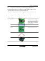
To our customers, Old Company Name in Catalogs and Other Documents On April 1st, 2010, NEC Electronics Corporation merged with Renesas Technology Corporation, and Renesas Electronics Corporation took over all the business of both companies. Therefore, although the old company name remains in this document, it is a valid Renesas Electronics document. We appreciate your understanding. Renesas Electronics website: http://www.renesas.com April 1st, 2010 Renesas Electronics Corporation Issued by: Renesas Electronics Corporation (http://www.renesas.com) Send any inquiries to http://www.renesas.com/inquiry. Notice 1. 2. 3. 4. 5. 6. 7. All information included in this document is current as of the date this document is issued. Such information, however, is subject to change without any prior notice. Before purchasing or using any Renesas Electronics products listed herein, please confirm the latest product information with a Renesas Electronics sales office. Also, please pay regular and careful attention to additional and different information to be disclosed by Renesas Electronics such as that disclosed through our website. Renesas Electronics does not assume any liability for infringement of patents, copyrights, or other intellectual property rights of third parties by or arising from the use of Renesas Electronics products or technical information described in this document. No license, express, implied or otherwise, is granted hereby under any patents, copyrights or other intellectual property rights of Renesas Electronics or others. You should not alter, modify, copy, or otherwise misappropriate any Renesas Electronics product, whether in whole or in part. Descriptions of circuits, software and other related information in this document are provided only to illustrate the operation of semiconductor products and application examples. You are fully responsible for the incorporation of these circuits, software, and information in the design of your equipment. Renesas Electronics assumes no responsibility for any losses incurred by you or third parties arising from the use of these circuits, software, or information. When exporting the products or technology described in this document, you should comply with the applicable export control laws and regulations and follow the procedures required by such laws and regulations. You should not use Renesas Electronics products or the technology described in this document for any purpose relating to military applications or use by the military, including but not limited to the development of weapons of mass destruction. Renesas Electronics products and technology may not be used for or incorporated into any products or systems whose manufacture, use, or sale is prohibited under any applicable domestic or foreign laws or regulations. Renesas Electronics has used reasonable care in preparing the information included in this document, but Renesas Electronics does not warrant that such information is error free. Renesas Electronics assumes no liability whatsoever for any damages incurred by you resulting from errors in or omissions from the information included herein. Renesas Electronics products are classified according to the following three quality grades: “Standard”, “High Quality”, and “Specific”. The recommended applications for each Renesas Electronics product depends on the product’s quality grade, as indicated below. You must check the quality grade of each Renesas Electronics product before using it in a particular application. You may not use any Renesas Electronics product for any application categorized as “Specific” without the prior written consent of Renesas Electronics. Further, you may not use any Renesas Electronics product for any application for which it is not intended without the prior written consent of Renesas Electronics. Renesas Electronics shall not be in any way liable for any damages or losses incurred by you or third parties arising from the use of any Renesas Electronics product for an application categorized as “Specific” or for which the product is not intended where you have failed to obtain the prior written consent of Renesas Electronics. The quality grade of each Renesas Electronics product is “Standard” unless otherwise expressly specified in a Renesas Electronics data sheets or data books, etc. “Standard”: 8. 9. 10. 11. 12. Computers; office equipment; communications equipment; test and measurement equipment; audio and visual equipment; home electronic appliances; machine tools; personal electronic equipment; and industrial robots. “High Quality”: Transportation equipment (automobiles, trains, ships, etc.); traffic control systems; anti-disaster systems; anticrime systems; safety equipment; and medical equipment not specifically designed for life support. “Specific”: Aircraft; aerospace equipment; submersible repeaters; nuclear reactor control systems; medical equipment or systems for life support (e.g. artificial life support devices or systems), surgical implantations, or healthcare intervention (e.g. excision, etc.), and any other applications or purposes that pose a direct threat to human life. You should use the Renesas Electronics products described in this document within the range specified by Renesas Electronics, especially with respect to the maximum rating, operating supply voltage range, movement power voltage range, heat radiation characteristics, installation and other product characteristics. Renesas Electronics shall have no liability for malfunctions or damages arising out of the use of Renesas Electronics products beyond such specified ranges. Although Renesas Electronics endeavors to improve the quality and reliability of its products, semiconductor products have specific characteristics such as the occurrence of failure at a certain rate and malfunctions under certain use conditions. Further, Renesas Electronics products are not subject to radiation resistance design. Please be sure to implement safety measures to guard them against the possibility of physical injury, and injury or damage caused by fire in the event of the failure of a Renesas Electronics product, such as safety design for hardware and software including but not limited to redundancy, fire control and malfunction prevention, appropriate treatment for aging degradation or any other appropriate measures. Because the evaluation of microcomputer software alone is very difficult, please evaluate the safety of the final products or system manufactured by you. Please contact a Renesas Electronics sales office for details as to environmental matters such as the environmental compatibility of each Renesas Electronics product. Please use Renesas Electronics products in compliance with all applicable laws and regulations that regulate the inclusion or use of controlled substances, including without limitation, the EU RoHS Directive. Renesas Electronics assumes no liability for damages or losses occurring as a result of your noncompliance with applicable laws and regulations. This document may not be reproduced or duplicated, in any form, in whole or in part, without prior written consent of Renesas Electronics. Please contact a Renesas Electronics sales office if you have any questions regarding the information contained in this document or Renesas Electronics products, or if you have any other inquiries. (Note 1) “Renesas Electronics” as used in this document means Renesas Electronics Corporation and also includes its majorityowned subsidiaries. (Note 2) “Renesas Electronics product(s)” means any product developed or manufactured by or for Renesas Electronics. User’s Manual SH7147 Group Debugging MCU Board HS7147EDB01H User’s Manual Renesas Microcomputer Development Environment System SuperH™ Family / SH7147 Series HS7147EDB01HE Rev.1.10 2008.04 Rev. 1.10 Apr. 04, 2008 Page ii of xiv REJ10J1783-0110 Notes regarding these materials 1. This document is provided for reference purposes only so that Renesas customers may select the appropriate Renesas products for their use. Renesas neither makes warranties or representations with respect to the accuracy or completeness of the information contained in this document nor grants any license to any intellectual property rights or any other rights of Renesas or any third party with respect to the information in this document. 2. Renesas shall have no liability for damages or infringement of any intellectual property or other rights arising out of the use of any information in this document, including, but not limited to, product data, diagrams, charts, programs, algorithms, and application circuit examples. 3. You should not use the products or the technology described in this document for the purpose of military applications such as the development of weapons of mass destruction or for the purpose of any other military use. When exporting the products or technology described herein, you should follow the applicable export control laws and regulations, and procedures required by such laws and regulations. 4. All information included in this document such as product data, diagrams, charts, programs, algorithms, and application circuit examples, is current as of the date this document is issued. Such information, however, is subject to change without any prior notice. Before purchasing or using any Renesas products listed in this document, please confirm the latest product information with a Renesas sales office. Also, please pay regular and careful attention to additional and different information to be disclosed by Renesas such as that disclosed through our website. (http://www.renesas.com ) 5. Renesas has used reasonable care in compiling the information included in this document, but Renesas assumes no liability whatsoever for any damages incurred as a result of errors or omissions in the information included in this document. 6. When using or otherwise relying on the information in this document, you should evaluate the information in light of the total system before deciding about the applicability of such information to the intended application. Renesas makes no representations, warranties or guaranties regarding the suitability of its products for any particular application and specifically disclaims any liability arising out of the application and use of the information in this document or Renesas products. 7. With the exception of products specified by Renesas as suitable for automobile applications, Renesas products are not designed, manufactured or tested for applications or otherwise in systems the failure or malfunction of which may cause a direct threat to human life or create a risk of human injury or which require especially high quality and reliability such as safety systems, or equipment or systems for transportation and traffic, healthcare, combustion control, aerospace and aeronautics, nuclear power, or undersea communication transmission. If you are considering the use of our products for such purposes, please contact a Renesas sales office beforehand. Renesas shall have no liability for damages arising out of the uses set forth above. 8. Notwithstanding the preceding paragraph, you should not use Renesas products for the purposes listed below: (1) artificial life support devices or systems (2) surgical implantations (3) healthcare intervention (e.g., excision, administration of medication, etc.) (4) any other purposes that pose a direct threat to human life Renesas shall have no liability for damages arising out of the uses set forth in the above and purchasers who elect to use Renesas products in any of the foregoing applications shall indemnify and hold harmless Renesas Technology Corp., its affiliated companies and their officers, directors, and employees against any and all damages arising out of such applications. 9. You should use the products described herein within the range specified by Renesas, especially with respect to the maximum rating, operating supply voltage range, movement power voltage range, heat radiation characteristics, installation and other product characteristics. Renesas shall have no liability for malfunctions or damages arising out of the use of Renesas products beyond such specified ranges. 10. Although Renesas endeavors to improve the quality and reliability of its products, IC products have specific characteristics such as the occurrence of failure at a certain rate and malfunctions under certain use conditions. Please be sure to implement safety measures to guard against the possibility of physical injury, and injury or damage caused by fire in the event of the failure of a Renesas product, such as safety design for hardware and software including but not limited to redundancy, fire control and malfunction prevention, appropriate treatment for aging degradation or any other applicable measures. Among others, since the evaluation of microcomputer software alone is very difficult, please evaluate the safety of the final products or system manufactured by you. 11. In case Renesas products listed in this document are detached from the products to which the Renesas products are attached or affixed, the risk of accident such as swallowing by infants and small children is very high. You should implement safety measures so that Renesas products may not be easily detached from your products. Renesas shall have no liability for damages arising out of such detachment. 12. This document may not be reproduced or duplicated, in any form, in whole or in part, without prior written approval from Renesas. 13. Please contact a Renesas sales office if you have any questions regarding the information contained in this document, Renesas semiconductor products, or if you have any other inquiries. Rev. 1.10 Apr. 04, 2008 Page iii of xiv REJ10J1783-0110 Rev. 1.10 Apr. 04, 2008 Page iv of xiv REJ10J1783-0110 IMPORTANT INFORMATION READ FIRST • READ this user's manual before using this emulator product. • KEEP the user's manual handy for future reference. Do not attempt to use the emulator product until you fully understand its mechanism. Emulator Product: Throughout this document, the term "emulator product" shall be defined as the following products produced only by Renesas Technology Corp. and Renesas Solutions Corp. excluding all subsidiary products. • E10A-USB emulator main unit • Debugging MCU board The user system or a host computer is not included in this definition. Purpose of the Debugging MCU Board: This debugging MCU board is used to connect the E10A-USB emulator to the user system. This debugging MCU board must only be used for the above purpose. Limited Applications: This emulator product is not authorized for use in transportation, vehicular, medical (where human life is potentially at stake), aerospace, nuclear, or undersea repeater applications. Buyers of this emulator product must notify Renesas Technology Corporation, Renesas Solutions Corporation or an authorized Renesas Technology product distributor before planning to use the product in such applications. Improvement Policy: Renesas Technology Corp. (including its subsidiaries, hereafter collectively referred to as Renesas) pursues a policy of continuing improvement in design, performance, and safety of the emulator product. Renesas reserves the right to change, wholly or partially, the specifications, design, user's manual, and other documentation at any time without notice. Rev. 1.10 Apr. 04, 2008 Page v of xiv REJ10J1783-0110 Target User of the Emulator Product: This emulator product should only be used by those who have carefully read and thoroughly understood the information and restrictions contained in the user's manual. Do not attempt to use the emulator product until you fully understand its mechanism. It is highly recommended that first-time users be instructed by users that are well versed in the operation of the emulator product. Users are required to be familiar with the basic knowledge for the electric circuits, logic circuits, and microcomputers. Precautions to be Taken when Using This Product: 1. This emulator is a development supporting unit for use in your program development and evaluation stages. In mass-producing your program you have finished developing, be sure to make a judgment on your own risk that it can be put to practical use by performing integration test, evaluation, or some experiment else. 2. In no event shall Renesas Solutions Corporation be liable for any consequence arising from the use of this emulator. 3. Renesas Solutions Corporation strives to renovate or provide a workaround for product malfunction at some charge or without charge. However, this does not necessarily mean that Renesas Solutions Corporation guarantees the renovation or the provision under any circumstances. 4. This emulator has been developed by assuming its use for program development and evaluation in laboratories. Therefore, it does not fall under the application of Electrical Appliance and Material Safety Law and protection against electromagnetic interference when used in Japan. 5. This emulator does not conform to safety standards such as UL or IEC. Be careful when you take this emulator overseas. 6. Renesas cannot anticipate every possible circumstance that might involve a potential hazard. The warnings in this user's manual and on the emulator product are therefore not all inclusive. Therefore, you must use the emulator product safely at your own risk. Rev. 1.10 Apr. 04, 2008 Page vi of xiv REJ10J1783-0110 LIMITED WARRANTY Renesas warrants its emulator products to be manufactured in accordance with published specifications and free from defects in material and/or workmanship. Renesas, at its option, will replace any emulator products returned intact to the factory, transportation charges prepaid, which Renesas, upon inspection, shall determine to be defective in material and/or workmanship. The foregoing shall constitute the sole remedy for any breach of Renesas’ warranty. See the Renesas warranty booklet for details on the warranty period. This warranty extends only to you, the original Purchaser. It is not transferable to anyone who subsequently purchases the emulator product from you. Renesas is not liable for any claim made by a third party or made by you for a third party. DISCLAIMER RENESAS MAKES NO WARRANTIES, EITHER EXPRESS OR IMPLIED, ORAL OR WRITTEN, EXCEPT AS PROVIDED HEREIN, INCLUDING WITHOUT LIMITATION THEREOF, WARRANTIES AS TO MARKETABILITY, MERCHANTABILITY, FITNESS FOR ANY PARTICULAR PURPOSE OR USE, OR AGAINST INFRINGEMENT OF ANY PATENT. IN NO EVENT SHALL RENESAS BE LIABLE FOR ANY DIRECT, INCIDENTAL OR CONSEQUENTIAL DAMAGES OF ANY NATURE, OR LOSSES OR EXPENSES RESULTING FROM ANY DEFECTIVE EMULATOR PRODUCT, THE USE OF ANY EMULATOR PRODUCT, OR ITS DOCUMENTATION, EVEN IF ADVISED OF THE POSSIBILITY OF SUCH DAMAGES. EXCEPT AS EXPRESSLY STATED OTHERWISE IN THIS WARRANTY, THIS EMULATOR PRODUCT IS SOLD "AS IS ", AND YOU MUST ASSUME ALL RISK FOR THE USE AND RESULTS OBTAINED FROM THE EMULATOR PRODUCT. Rev. 1.10 Apr. 04, 2008 Page vii of xiv REJ10J1783-0110 State Law: Some states do not allow the exclusion or limitation of implied warranties or liability for incidental or consequential damages, so the above limitation or exclusion may not apply to you. This warranty gives you specific legal rights, and you may have other rights which may vary from state to state. The Warranty is Void in the Following Cases: Renesas shall have no liability or legal responsibility for any problems caused by misuse, abuse, misapplication, neglect, improper handling, installation, repair or modifications of the emulator product without Renesas’ prior written consent or any problems caused by the user system. All Rights Reserved: 1. Circuitry and other examples described herein are meant merely to indicate the characteristics and performance of Renesas’ semiconductor products. Renesas assumes no responsibility for any intellectual property claims or other problems that may result from applications based on the examples described herein. 2. No license is granted by implication or otherwise under any patents or other rights of any third party or Renesas. 3. This user's manual and emulator product are copyrighted and all rights are reserved by Renesas. No part of this user's manual, all or part, may be reproduced or duplicated in any form, in hard-copy or machine-readable form, by any means available without Renesas’ prior written consent. Figures: Some figures in this user's manual may show items different from your actual system. Rev. 1.10 Apr. 04, 2008 Page viii of xiv REJ10J1783-0110 SAFETY PAGE READ FIRST • READ this user's manual before using this emulator product. • KEEP the user's manual handy for future reference. Do not attempt to use the emulator product until you fully understand its mechanism. DEFINITION OF SIGNAL WORDS Either in the user's manual or on the product, several icons are used to insure proper handling of this product and also to prevent injuries to you or other persons, or damage to your properties. Their graphic images and meanings are given in this safety page. Be sure to read this chapter before using the product. This is the safety alert symbol. It is used to alert you to potential personal injury hazards. Obey all safety messages that follow this symbol to avoid possible injury or death. DANGER WARNING CAUTION CAUTION DANGER indicates an imminently hazardous situation which, if not avoided, will result in death or serious injury. WARNING indicates a potentially hazardous situation which, if not avoided, could result in death or serious injury. CAUTION indicates a potentially hazardous situation which, if not avoided, may result in minor or moderate injury. CAUTION used without the safety alert symbol indicates a potentially hazardous situation which, if not avoided, may result in property damage. NOTE emphasizes essential information. In addition to the four above, the following are also used as appropriate. Rev. 1.10 Apr. 04, 2008 Page ix of xiv REJ10J1783-0110 WARNING Observe the precautions listed below. Failure to do so will result in a FIRE HAZARD and will damage the user system and the emulator product or will result in PERSONAL INJURY. The USER PROGRAM will be LOST. 1. Do not repair or remodel the emulator product by yourself for electric shock prevention and quality assurance. 2. Always switch OFF the emulator and user system before connecting or disconnecting any CABLES or PARTS. 3. Always before connecting any CABLES, make sure that pin 1 on both sides are correctly aligned. Rev. 1.10 Apr. 04, 2008 Page x of xiv REJ10J1783-0110 User Registration When you have purchased the emulator represented in this user's manual, be sure to register it. As the H/W Tool Customer Registration Sheet is included with this product, fill it in and send the same contents to the following address by an email. Your registered information is used for only after-sale services, and not for any other purposes. Without user registration, you will not be able to receive maintenance services such as a notification of field changes or trouble information. So be sure to carry out the user registration. For more information about user registration, send an email to the following address. [email protected] Rev. 1.10 Apr. 04, 2008 Page xi of xiv REJ10J1783-0110 Rev. 1.10 Apr. 04, 2008 Page xii of xiv REJ10J1783-0110 Contents Section 1 Product Overview ..............................................................................1 1.1 1.2 1.3 1.4 1.5 Introduction....................................................................................................................... 1 Components ...................................................................................................................... 4 Components in the Package for the Debugging MCU Board ........................................... 5 Hardware Configuration ................................................................................................... 8 1.4.1 Configuration of the Main Unit of the Debugging MCU Board .......................... 9 1.4.2 Configuration of the User System Interface Board.............................................. 14 Environmental Conditions ................................................................................................ 15 Section 2 Setting Up the Debugging MCU Board.............................................17 2.1 2.2 2.3 2.4 Flow Chart before Using the Debugging MCU Board...................................................... 17 Setting Up the Debugging MCU Board ............................................................................ 18 2.2.1 Connecting the Debugging MCU Board to the E10A-USB Emulator................. 18 2.2.2 Connecting the Debugging MCU Board to the User System............................... 20 2.2.3 Setting the Power-Selection Switch ..................................................................... 23 2.2.4 Connecting the Power Cable................................................................................ 24 2.2.5 Setting the Clock-Selection Jumper..................................................................... 25 2.2.6 Installing a Crystal Resonator .............................................................................. 26 2.2.7 Setting the User-System Input Signal Enabling/Disabling Switches ................... 27 2.2.8 Connecting the System Ground ........................................................................... 29 Setting the E10A-USB Emulator ...................................................................................... 30 2.3.1 Setting the DIP Switches of the E10A-USB Emulator ........................................ 30 2.3.2 CD-R.................................................................................................................... 31 2.3.3 Connecting the E10A-USB Emulator to the Host Computer............................... 32 2.3.4 Setting Up the E10A-USB Emulator ................................................................... 33 2.3.5 Activating the High-performance Embedded Workshop..................................... 33 Setting Up the Debugging MCU Board for Single Operation .......................................... 34 2.4.1 Setting Switches on the Debugging MCU Board................................................. 34 2.4.2 Inputting Reset Signals to the Debugging MCU Board ....................................... 35 Section 3 Hardware Specifications ....................................................................37 3.1 3.2 3.3 3.4 3.5 External Dimensions of the Debugging MCU Board ....................................................... 37 Resulting Dimensions after Connecting User System Interface Board............................. 39 Recommended Dimensions for User System Mount Pad (Footprint)............................... 40 Installing the MCU to the User System ............................................................................ 41 User System Interface Circuits.......................................................................................... 43 Rev. 1.10 Apr. 04, 2008 Page xiii of xiv REJ10J1783-0110 3.6 Delay Time for the User System Interface........................................................................ 47 Section 4 Maintenance and Guarantee ..............................................................49 4.1 4.2 4.3 4.4 4.5 User Registration .............................................................................................................. 49 Maintenance...................................................................................................................... 49 Guarantee.......................................................................................................................... 49 Repair Provisions.............................................................................................................. 50 4.4.1 Repair with Extra-Charge .................................................................................... 50 4.4.2 Replacement with Extra-Charge .......................................................................... 50 4.4.3 Expiration of the Repair Period ........................................................................... 50 4.4.4 Transportation Fees at Sending Your Product for Repair .................................... 50 How to Make a Request for Repair................................................................................... 51 Appendix A Repair Request Sheet ....................................................................53 Rev. 1.10 Apr. 04, 2008 Page xiv of xiv REJ10J1783-0110 Section 1 Product Overview Section 1 Product Overview 1.1 Introduction The High-performance Embedded Workshop is a graphical user interface intended to ease the development and debugging of applications written in C/C++ programming language and assembly language for Renesas microcomputers. Its aim is to provide a powerful yet intuitive way of accessing, measuring, and modifying the debugging platform in which the application is running. This system is a software and hardware development support tool for application systems using the Renesas original microcomputer. The debugging MCU board is connected to the user system through the IC socket on the user system. The user system can be debugged under the conditions similar to the actual application conditions. The debugging MCU board enables debugging anywhere indoors or out with the E10A-USB emulator. The host computer for controlling the debugging MCU board must be an IBM PC compatible machine with USB 1.1/2.0 (Full-Speed). Rev. 1.10 Apr. 04, 2008 Page 1 of 56 REJ10J1783-0110 Section 1 Product Overview Host computer External power supply High-performance Embedded Workshop CD-R 5-V DC USB 1.1/2.0 (Full-Speed) User system Debugging MCU board E10A-USB emulator Figure 1.1 System Configuration with the Debugging MCU Board Rev. 1.10 Apr. 04, 2008 Page 2 of 56 REJ10J1783-0110 Section 1 Product Overview The debugging MCU board provides the following features: • Excellent cost-performance in-circuit emulator Using the debugging MCU board with the E10A-USB emulator implements low-cost debugging of the user system without the user pins being occupied by the debugging interface (H-UDI). When the AUD function on the debugging MCU board is used, the debugging MCU board supports the window trace function for trace acquisition of a large-capacity realtime trace or a memory access (memory access address or memory access data) within the specified ranges. • Realtime emulation Realtime emulation of the user system is enabled at the maximum operating frequency of the CPU. • Excellent operability ® ® ® Using the High-performance Embedded Workshop on the Microsoft , Microsoft Windows ® ® 2000, and Microsoft Windows XP operating systems enables user program debugging using a pointing device such as a mouse. The High-performance Embedded Workshop enables highspeed downloading of load module files. • Debugging of the user system in the final development stage The user system can be debugged under conditions similar to the actual application conditions. • Compact debugging environment When the emulator is used, a laptop computer can be used as a host computer, creating a debugging environment in any place. Rev. 1.10 Apr. 04, 2008 Page 3 of 56 REJ10J1783-0110 Section 1 Product Overview CAUTION READ the following warnings before using the debugging MCU board. Incorrect operation will damage the user system and the debugging MCU board. The USER PROGRAM will be LOST. 1. Check all components against the component list after unpacking the emulator. 2. Never place heavy objects on the casing. 3. Protect the emulator from excessive impacts and stresses. For details, refer to section 1.5, Environmental Conditions. 4. Only supply the power of the specified voltages or power-supply frequencies to the debugging MCU board. 5. When moving the host computer or user system, take care not to vibrate or damage it. 6 After connecting the cable, check that it is connected correctly. For details, refer to section 2, Setting Up the Debugging MCU Board. 7. Supply power to the connected equipment after connecting all cables. Cables must not be connected or removed while the power is on. 1.2 Components After removing the product from its packaging, confirm that you have all of the components. For details on the components of the debugging MCU board, refer to section 1.3, Components in the Package for the Debugging MCU Board. If any component is not present, contact your nearest Renesas sales office. Rev. 1.10 Apr. 04, 2008 Page 4 of 56 REJ10J1783-0110 Section 1 Product Overview 1.3 Components in the Package for the Debugging MCU Board The debugging MCU board supports the SH7147 group (SH7142/SH7147). Table 1.1 lists the components supplied in the package for the debugging MCU board. In the product as shipped, the main unit of the debugging MCU board is connected to the user system interface board with the flexible flat cable (FFC). Do not detach them from each other. Table 1.1 Components in the Package for the Debugging MCU Board Classification Component Hardware Debugging MCU board main unit Appearance Qty Remarks 1 Depth: 80.0 mm, width: 85.0 mm, height: 22.3 mm, mass: 56.0 g * The main unit of the debugging MCU board is connected to the user system interface board with the FFC cable. Do not disconnect these components. FFC cables 2 Length: 150.0 mm, mass: 1.4 g User system interface board 1 Depth: 35.0 mm, width: 40.0 mm, height: 10.3 mm, mass: 9.5 g Power cable 1 Length: 0.5 m IC socket 1 Connect the IC socket to the user system. Rev. 1.10 Apr. 04, 2008 Page 5 of 56 REJ10J1783-0110 Section 1 Product Overview Table 1.1 Components in the Package for the Debugging MCU Board (cont.) Classification Component Hardware (cont.) Qty Remarks Socket cover 1 For installing the MCU Screws (M2.0 x 10 mm) 4 For fastening the user system interface board Screws (M2.0 x 6 mm) 4 For fastening the socket cover Guide pins 3 Screwdriver 1 User’s manual 1 Rev. 1.10 Apr. 04, 2008 Page 6 of 56 REJ10J1783-0110 Appearance SH7147 Group Debugging MCU Board User’s Manual (this manual) Section 1 Product Overview CAUTION Use the following IC sockets and socket covers on the user sytem. • For SH7147 (package code: PLQP0100KB-A; former code: FP-100UV): IC socket: NQPACK100SD-ND (manufactured by Tokyo Eletech Corporation) IC socket cover: HQPACK100SD (manufactured by Tokyo Eletech Corporation) Rev. 1.10 Apr. 04, 2008 Page 7 of 56 REJ10J1783-0110 Section 1 Product Overview 1.4 Hardware Configuration As shown in figure 1.2, the usable configuration of the debugging MCU board consists of the main unit, FFC cable, user system interface board, and power cable. The debugging MCU board is connected, via the E10A-USB emulator, to the host computer over a USB 1.1/2.0 (Full-Speed) link. The host computer, E10A-USB emulator, and external power supply must be separately obtained by the user. Host computer External power supply (5-V DC) USB1.1/USB2.0 (Full-Speed) E10A-USB emulator (separately available) Power cable User system interface board FFC cable Main unit of the debugging MCU board User system (IC-socket interface) Figure 1.2 Hardware Configuration of the Debugging MCU Board Rev. 1.10 Apr. 04, 2008 Page 8 of 56 REJ10J1783-0110 Section 1 Product Overview 1.4.1 Configuration of the Main Unit of the Debugging MCU Board The names of each section of the debugging MCU board are explained below. Top of the Main Unit of the Debugging MCU Board (1) Figure 1.3 Top of the Main Unit of the Debugging MCU Board (1) Rev. 1.10 Apr. 04, 2008 Page 9 of 56 REJ10J1783-0110 Section 1 Product Overview (a) External power LED: Marked ‘BOARD POWER’. This LED is lit while external power is being supplied from the power cable or from the user system to the PVCC pin of the MCU.The source of the power supply is determined by the setting of the power-selection switch. (b) User VCC LED: Marked ‘USER VCC’. This LED is lit while power is being supplied from the user system to the VCC pin of the MCU. (c) User AVCC LED: Marked ‘USER AVCC’. This LED is lit while power is being supplied from the user system to the AVCC pin of the MCU. (d) Reset LED: Marked ‘RST’. This LED is lit while the reset signal is being input to the MCU. Top of the Main Unit of the Debugging MCU Board (2) Figure 1.4 Top of the Main Unit of the Debugging MCU Board (2) Rev. 1.10 Apr. 04, 2008 Page 10 of 56 REJ10J1783-0110 Section 1 Product Overview (a) Power-selection switch: This switch is used to select the power source for the debugging MCU board. When ‘EXTERNAL’ is selected, an external power supply is the source for the debugging MCU board. When ‘USER SYSTEM’ is selected, the PVCC power supply on the user system is the source for the debugging MCU board. (b) Clock-selection jumper: This jumper is used to select the clock signal for input to the MCU on the debugging MCU board. When ‘XTAL’ is selected, the input clock signal is from the crystal resonator on the debugging MCU board. When ‘USER CLK’ is selected, the input clock signal is from the EXTAL pin on the user system. Note: A crystal resonator on the user system is not supported. (c) Crystal-resonator installation sockets: The crystal resonator for supplying the external clock signal is mounted here when ‘XTAL’ has been selected on the clock-selection jumper. (d) Reset switch: This switch is used to input reset signals manually to the debugging MCU board. (e) User-system input signal enabling/disabling switches: These switches are used to enable or disable the input of /RES and NMI signals from the user system and connect or disconnect the user system. When the MD signal from the user system has been disabled, this switch also sets input of the MD signal to the MCU board. Rev. 1.10 Apr. 04, 2008 Page 11 of 56 REJ10J1783-0110 Section 1 Product Overview Top of the Main Unit of the Debugging MCU Board (3) Figure 1.5 Top of the Main Unit of the Debugging MCU Board (3) (a) Power-cable connector: This connector is used to connect the debugging MCU board to the power cable for the external power supply. (b) H-UDI interface connector (36 pins): This connector is used to connect the debugging MCU board to the 36pin cable of the E10A-USB emulator. (c) H-UDI interface connector (14 pins): This connector is used to connect the debugging MCU board to the 14pin cable of the E10A-USB emulator. (d) User system interface connector 1: This connector is used to connect the main unit of the debugging MCU board to the FFC cable. Note: The FFC cable already occupies this connector in the product as shipped. Do not remove the cable from the connector. Rev. 1.10 Apr. 04, 2008 Page 12 of 56 REJ10J1783-0110 Section 1 Product Overview Bottom of the Main Unit of the Debugging MCU Board Figure 1.6 Bottom of the Main Unit of the Debugging MCU Board (a) User system interface connector 2: This connector is used to connect the main unit of the debugging MCU board to the FFC cable. Note: The FFC cable already occupies this connector in the product as shipped. Do not remove the cable from the connector. Rev. 1.10 Apr. 04, 2008 Page 13 of 56 REJ10J1783-0110 Section 1 Product Overview 1.4.2 Configuration of the User System Interface Board The names of each section of the user system interface board are explained below. (1) Top of the user system interface board (a) (2) Bottom of the user system interface board (b) (c) Figure 1.7 User System Interface Board (a) User system interface connector 1: This connector is used to connect the user system interface board to the FFC cable. Note: The FFC cable already occupies this connector in the product as shipped. Do not remove the cable from the connector. (b) User system interface connector 2: This connector is used to connect the user system interface board to the FFC cable. Note: The FFC cable already occupies this connector in the product as shipped. Do not remove the cable from the connector. (c) User system connector: This connector is for connection to the user system. Rev. 1.10 Apr. 04, 2008 Page 14 of 56 REJ10J1783-0110 Section 1 Product Overview 1.5 Environmental Conditions CAUTION Observe the conditions listed in tables 1.6 and 1.7 when using the debugging MCU board. Failure to do so can lead to abnormal operation of the user system, the debugging MCU board, and the user program. Table 1.6 Environmental Conditions Item Specifications Temperature Operating: +10°C to +35°C Storage: –10°C to +50°C Humidity Operating: 35% RH to 80% RH, no condensation Storage: 35% RH to 80% RH, no condensation Vibration Operating: 2.45 m/s max. 2 Storage: 4.9 m/s max. 2 Transportation: 14.7 m/s max. Ambient gases No corrosive gases may be present 2 Table 1.7 Operating Environment Item Description Host computer IBM PC or compatible machine that satisfies the operating-environment conditions of the E10A-USB emulator Emulator Renesas microcomputer development tool: E10A-USB emulator (HS0005KCU01H or HS0005KCU02H) Power supply DC 5 V ± 10% Supply current 500 mA (max.) Rev. 1.10 Apr. 04, 2008 Page 15 of 56 REJ10J1783-0110 Section 1 Product Overview Rev. 1.10 Apr. 04, 2008 Page 16 of 56 REJ10J1783-0110 Section 2 Setting Up the Debugging MCU Board Section 2 Setting Up the Debugging MCU Board 2.1 Flow Chart before Using the Debugging MCU Board Unpack the debugging MCU board and prepare it for use as follows: WARNING READ the reference sections shaded in figure 2.1 before using the debugging MCU board. Incorrect operation will damage the user system and the debugging MCU board uct. The USER PROGRAM will be LOST. Reference Unpack the debugging MCU board Component list Check the components against the component list Set up the debugging MCU board - Connect the E10A-USB emulator - Connect the user system - Set the switches of the debugging MCU board Section 2 in the Debugging MCU Board User's Manual (this manual) Set up the E10A-USB emulator - Install the emulator's software (Check the components and register the user information.) - Insert the emulator - Set up the main unit of the emulator Section 3 in the E10A-USB Emulator User's Manual Start the High-performance Embedded Workshop Turn on the user system Section 4 in the E10A-USB Emulator User's Manual When the debugging MCU board is used first. When the debugging MCU board is used for second time or later. Input the user system reset signal Figure 2.1 Preparation Flow Chart for the Debugging MCU Board Rev. 1.10 Apr. 04, 2008 Page 17 of 56 REJ10J1783-0110 Section 2 Setting Up the Debugging MCU Board 2.2 Setting Up the Debugging MCU Board To apply the debugging MCU board, you must obtain an E10A-USB emulator. This section describes how to connect the debugging MCU board, the E10A-USB emulator, and the user system interface board. Before making the connections, check that the host computer is turned off, the E10A-USB emulator is not connected to the host computer via the USB cable, and power is being supplied to neither the debugging MCU board nor the user system. 2.2.1 Connecting the Debugging MCU Board to the E10A-USB Emulator Follow the below procedure to connect the debugging MCU board to the E10A-USB emulator. 1. Connect the user system interface cable (14 or 36 pins) provided with the E10A-USB emulator to the side connector of the E10A-USB emulator as shown in figure 2.2. Figure 2.2 Connecting the E10A-USB Emulator to the User System Interface Cable Rev. 1.10 Apr. 04, 2008 Page 18 of 56 REJ10J1783-0110 Section 2 Setting Up the Debugging MCU Board 2. Connect the 14-pin or 36-pin connector of the user system interface cable to the H-UDI interface connector on the debugging MCU board as shown in figures 2.3 and 2.4. Connect the 36-pin or 14-pin connector to CN2 or CN3, respectively. Figure 2.3 Connecting the User System Interface Cable (36 Pins) to the Debugging MCU Board Rev. 1.10 Apr. 04, 2008 Page 19 of 56 REJ10J1783-0110 Section 2 Setting Up the Debugging MCU Board Figure 2.4 Connecting the User System Interface Cable (14 Pins) to the Debugging MCU Board Rev. 1.10 Apr. 04, 2008 Page 20 of 56 REJ10J1783-0110 Section 2 Setting Up the Debugging MCU Board 2.2.2 Connecting the Debugging MCU Board to the User System To connect the debugging MCU board to the user system, follow the instructions below. WARNING Always switch OFF the emulator product, the debugging MCU board, and the user system before any connection or removal of the USER SYSTEM INTERFACE BOARD. Furthermore, make sure that the pin 1 positions on both sides are correctly aligned. Failure to do so will create a FIRE HAZARD that can damage the emulator product, the debugging MCU board, the user system interface board, or the user system, or produce PERSONAL INJURY. 1. Solder the IC socket to the user system. CAUTION Before applying solder, use epoxy resin adhesive to affix the guide points on the IC socket to the user system. Ensure full wetting of the leads so that the solder flows over the leads and forms good fillets (use slightly more solder than you normally would). 2. Align pin 1 on the IC socket on the user system with pin 1 on the user system interface board, and plug the user system connector of the interface board into the IC socket on the user system, as is shown in figure 2.5. CAUTION Ensure that the locations of pin 1 on the socket and connector are aligned before inserting the connector. Rev. 1.10 Apr. 04, 2008 Page 21 of 56 REJ10J1783-0110 Section 2 Setting Up the Debugging MCU Board CAUTION 1. Use a Philips-head screwdriver with a head-size matching that of the screw. 2. The tightening torque must be no greater than 0.054 N•m. If the applied torque cannot be accurately measured, stop tightening the screw when the force required for further tightening suddenly becomes significantly greater than was initially required. Excessive tightening may break the screw head or crack the IC-socket solder, leading to an IC contact error. 3. If the emulator does not operate correctly, cracks may have been produced in the solder. Check conduction with a tester and re-solder the IC socket if necessary. Rev. 1.10 Apr. 04, 2008 Page 22 of 56 REJ10J1783-0110 Section 2 Setting Up the Debugging MCU Board 3. Fasten the user system interface board to the IC socket on the user system with the four screws (M2.0 x 10 mm) provided. Tighten each of the screws a little at a time, alternating between those on opposing corners. Do not concentrate on fully tightening one screw at a time. Take special care, such as manually securing the IC-socket soldered area, to prevent damage to the soldered IC socket due to excessive tightening of the screws or twisting of components. Screws (M2.0 x 10 mm) User system interface board Pin 1 IC socket User system Figure 2.5 Connecting the User System Interface Board to the User System Rev. 1.10 Apr. 04, 2008 Page 23 of 56 REJ10J1783-0110 Section 2 Setting Up the Debugging MCU Board 2.2.3 Setting the Power-Selection Switch This switch selects the external power supply (DC5V) or the PVCC power supply on the user system as the source of power for the debugging MCU board. Refer to table 2.1 when selecting the power supply to be used. Figure 2.6 Power-Selection Switch Table 2.1 Correspondence of Power-Selection Switch Settings Silk-Screened Label Power Supply to be Used EXTERNAL External power supply connected to the power cable (factory setting) USER SYSTEM PVCC on the user system Rev. 1.10 Apr. 04, 2008 Page 24 of 56 REJ10J1783-0110 Section 2 Setting Up the Debugging MCU Board 2.2.4 Connecting the Power Cable When the power-selection switch is set to ‘EXTERNAL’, the power cable must be connected to the debugging MCU board so that power can be supplied from beyond the board. Connect the power cable to the power-cable connector on the debugging MCU board as shown in figure 2.7. Since the debugging MCU board operates with the PVCC power supply when the power-selection switch is set to be ‘USER SYSTEM’, the power cable needed not to be connected. Figure 2.7 Connecting the Power Cable to the Debugging MCU Board Rev. 1.10 Apr. 04, 2008 Page 25 of 56 REJ10J1783-0110 Section 2 Setting Up the Debugging MCU Board 2.2.5 Setting the Clock-Selection Jumper The EXTAL input from the user system or the crystal resonator installed on the debugging MCU board can be selected as the source of the clock signal for the MCU. Refer to table 2.2 when selecting the clock. Figure 2.8 Clock-Selection Jumper Table 2.2 Correspondence of Clock-Selection Jumper Settings Silk-Screened Label Jumper Pin (SW3) Clock to be Used XTAL Pins 1-2 closed Crystal resonator installed on the debugging MCU board USER CLK Pins 2-3 closed EXTAL input from the user system (factory setting) Note: ‘XTAL’ should only be selected if a crystal resonator has been mounted across the crystalresonator installation sockets (X1) of the debugging MCU board. Users must provide the crystal resonator. Rev. 1.10 Apr. 04, 2008 Page 26 of 56 REJ10J1783-0110 Section 2 Setting Up the Debugging MCU Board 2.2.6 Installing a Crystal Resonator ‘XTAL’ should only be selected if a crystal resonator has been mounted on the debugging MCU board. Install the crystal resonator across the crystal-resonator installation sockets of the debugging MCU board. Figure 2.9 Installing a Crystal Resonator Rev. 1.10 Apr. 04, 2008 Page 27 of 56 REJ10J1783-0110 Section 2 Setting Up the Debugging MCU Board 2.2.7 Setting the User-System Input Signal Enabling/Disabling Switches These switches enable or disable the input of the /RES, NMI, and MD signals from the user system to the debugging MCU board. The block also includes switches to set a desired level for each MD signal when input of the MD signal from the user system has been disabled. Table 2.3 lists the signals and settings. Figure 2.10 User-System Input Signal Enabling/Disabling Switches Rev. 1.10 Apr. 04, 2008 Page 28 of 56 REJ10J1783-0110 Section 2 Setting Up the Debugging MCU Board Table 2.3 Correspondence of User-System Input Signal Enabling/Disabling Switch Settings Silk-Screened Label Number on SW1 High Low MD0 1 When input of the MD signals from the user system has been disabled, input the high level to MD0 (factory setting). When input of the MD signals from the user system has been disabled, input the low level to MD0 low level to the MD0. MD1 2 When input of the MD signals from the user system has been disabled, input the high level to MD1 (factory setting). When input of the MD signals from the user system has been disabled, input the low level to MD1. ⎯ 3 Do not change the position of this switch (factory setting). Do not change the position of this switch. Silk-Screened Label Number on SW1 DISABLE ENABLE UMD 4 Disable input of the MD signals from the user system and use the MD0 and MD1 settings made on this switch block (SW1). Enable input of the MD signals from the user system (factory setting). UNMI 5 Fix the NMI input to the high level. (factory setting). Enable input of the NMI signal from the user system (factory setting). URES 6 Fix the /RES input to high level. (factory setting). Enable input of the /RES signal from the user system (factory setting). Rev. 1.10 Apr. 04, 2008 Page 29 of 56 REJ10J1783-0110 Section 2 Setting Up the Debugging MCU Board 2.2.8 Connecting the System Ground WARNING Separate the frame ground and signal ground of the user system. Failure to do so will create a FIRE HAZARD that can damage the user system and emulator product, or produce PERSONAL INJURY. The signal grounds of the E10A-USB emulator and the debugging MCU board are connected to the user system's signal ground. In the emulator, the signal ground and frame ground are connected. In the user system, only connect the frame ground to earth; do not connect the signal ground to the frame ground (figure 2.11). If it is difficult to separate the frame ground from the signal ground in the user system, tie the frame ground of the user system to the same potential as the GND level of the DC power input (AC adapter) of the host computer. This is because differences in GND potential between the host computer and target system will lead to excessive flows of current in the low-impedance GND lines, and thin lines might burn out. Signal ground E10A-USB emulator Logic Host computer Signal Debugging MCU board User system Signal Logic USB Signal ground Signal ground Power supply Frame ground Figure 2.11 Connecting System Ground Rev. 1.10 Apr. 04, 2008 Page 30 of 56 REJ10J1783-0110 Section 2 Setting Up the Debugging MCU Board 2.3 2.3.1 Setting the E10A-USB Emulator Setting the DIP Switches of the E10A-USB Emulator Set the DIP switches of the E10A-USB emulator as follows. 1. Open the sliding switch cover in the lower right portion of the upper side of the E10A-USB emulator by sliding it to the right as shown in figure 2.12. 2. Turn all of the DIP switches (SW1, SW2, and SW3) on (‘1’ side). RENESAS B USB I/F US 0A E1 1 0 ACT 1 0 1 1 2 2 3 3 ON OFF Figure 2.12 Setting the DIP Switches of the E10A-USB Emulator Rev. 1.10 Apr. 04, 2008 Page 31 of 56 REJ10J1783-0110 Section 2 Setting Up the Debugging MCU Board 2.3.2 CD-R The emulator’s software for the debugging MCU board is included in the CD-R provided with the E10A-USB emulator. The root directory of the CD-R contains a setup program for installing the emulator’s software for the debugging MCU board. The folders contain the files and programs listed below. Table 2.4 Contents of the CD-R Directories Directory Name Contents ® Description Dlls Microsoft runtime library A runtime library for the High-performance Embedded Workshop. The version is checked at installation and this library is copied to the hard disk as part of the installation process. Drivers E10A-USB emulator driver USB drivers for the E10A-USB emulator. Help Online help for the E10A-USB emulator An online help file. This is copied to the hard disk as part of the installation process. Manual E10A-USB emulator manuals E10A-USB emulator user’s manuals. They are provided as PDF files. Execute HewInstMan.exe from the root directory of the CD-R to start the installation wizard. Follow the cues given by the installation wizard to install the software. Select the SH-2 device group in the wizard for selecting the device group to be installed. Note: When a driver is installed in Windows® XP, a warning message on the Windows® logo test may be displayed, but it is not a problem. Select [Continue Anyway] to proceed with driver installation. Rev. 1.10 Apr. 04, 2008 Page 32 of 56 REJ10J1783-0110 Section 2 Setting Up the Debugging MCU Board 2.3.3 Connecting the E10A-USB Emulator to the Host Computer This section describes how to connect the E10A-USB emulator to the host computer. For the position of each connector of the emulator, refer to the SuperH™ Family E10A-USB Emulator User’s Manual. Notes: 1. When [Add New Hardware Wizard] is displayed, select the [Search for the best driver for your device. (Recommended)] radio button and then the [Specify a location] check box to select the path to be searched for drivers. The location must be specified as <Drive>:\DRIVERS. (<Drive> is the CD drive letter.) 2. When a driver is installed in Windows® XP, a warning message on the Windows® logo test may be displayed, but it is not a problem. Select [Continue Anyway] to proceed with driver installation. 3. Be sure to install the software for the E10A-USB emulator before putting the emulator in place. WARNING Always switch OFF the emulator product and the user system before connecting or disconnecting any CABLES except for the USB interface cable. Failure to do so will result in a FIRE HAZARD and will damage the user system and the emulator product or will result in PERSONAL INJURY. The USER PROGRAM will be LOST. Rev. 1.10 Apr. 04, 2008 Page 33 of 56 REJ10J1783-0110 Section 2 Setting Up the Debugging MCU Board The E10A-USB emulator is connected to the host computer via the USB 1.1, and also to the USB port conforming to USB 2.0. Figure 2.13 shows the system configuration. Figure 2.13 System Configuration when Connecting the E10A-USB Emulator to the Host Computer 2.3.4 Setting Up the E10A-USB Emulator Set up the E10A-USB emulator’s firmware referring to section 3.10, Setting Up the Emulator, and section 3.11, System Check, in the SuperH™ Family E10A-USB Emulator User’s Manual. 2.3.5 Activating the High-performance Embedded Workshop Activate the High-performance Embedded Workshop referring to section 4, Preparations for Debugging, in the SuperH™ Family E10A-USB Emulator User’s Manual, which describes the activation procedure. Rev. 1.10 Apr. 04, 2008 Page 34 of 56 REJ10J1783-0110 Section 2 Setting Up the Debugging MCU Board 2.4 Setting Up the Debugging MCU Board for Single Operation Since the debugging MCU board can be initiated even if the user system has not been connected, it is available for simple evaluation before designing the user system. WARNING 1. Always disconnect the E10A-USB emulator from the host computer and switch OFF the debugging MCU board before setting switches on the debugging MCU board. Failure to do so will create a FIRE HAZARD that can damage the E10A-USB emulator product, the debugging MCU board, or the user system interface board. 2. For the single operation of the debugging MCU board, connector pins on the bottom of the user system interface board, which are used for connecting the user system, are disconnected. To prevent connector pins from being shorted, be sure to put an insulator under the user system interface board. 2.4.1 Setting Switches on the Debugging MCU Board For the single operation of the debugging MCU board, set the switches on the debugging MCU board as described below and activate the High-performance Embedded Workshop. 1. Only the external power supply is supported. Set the power-selection switch to ‘EXTERNAL’ and supply the external power (DC5V) from the power-cable connector. 2. Only the crystal resonator installed on the debugging MCU board is supported as the source of the clock signal. Set the clock-selection jumper to ‘XTAL’ to install the crystal resonator across the crystalresonator installation sockets. 3. If the debugging MCU board is to operate in stand-alone mode, the user-system input signal enabling/disabling switch block must be set on the debugging MCU board. Set switches UMD, URES, and UNMI to the ‘DISABLE’ position and set switches MD0 and MD1 to the levels which correspond to the desired MCU mode. Rev. 1.10 Apr. 04, 2008 Page 35 of 56 REJ10J1783-0110 Section 2 Setting Up the Debugging MCU Board 2.4.2 Inputting Reset Signals to the Debugging MCU Board When reset signals must be input, such as the case when activating the High-performance Embedded Workshop or debugging, they can be manually input from the reset switch on the debugging MCU board. For details on inputting reset signals, see table 2.5. Figure 2.14 Reset Switch Table 2.5 Correspondence of Reset Switch Settings Setting of SW4 Reset Signal Input to the Debugging MCU Board Turned to ‘3’ of silkscreened label Reset signal input from the reset switch is canceled. (factory setting) Turned to ‘1’ of silkscreened label Reset signal is input from the reset switch. Note: This reset switch is used to manually input reset signals to the debugging MCU board. When the user system is connected, this reset switch is also available for inputting reset signals to the debugging MCU board, however, note that no reset signal is output to the user system. Rev. 1.10 Apr. 04, 2008 Page 36 of 56 REJ10J1783-0110 Section 3 Hardware Specifications Section 3 Hardware Specifications 3.1 External Dimensions of the Debugging MCU Board Figures 3.1 through 3.3 show the external dimensions of the debugging MCU board. 274.0 80.0 149.0 Unit:mm Tolerance: ±0.5 mm Figure 3.1 External Dimensions of the Debugging MCU Board 80.0 85.0 Unit: mm Tolerance: ±0.5 mm Figure 3.2 External Dimensions of the Main Unit of the Debugging MCU Board Rev. 1.10 Apr. 04, 2008 Page 37 of 56 REJ10J1783-0110 Section 3 Hardware Specifications 40.0 35.0 17.5 12.5 Pin 1 Unit:mm Tolerance:0.5mm Figure 3.3 External Dimensions of the User System Interface Board Rev. 1.10 Apr. 04, 2008 Page 38 of 56 REJ10J1783-0110 Section 3 Hardware Specifications 3.2 Resulting Dimensions after Connecting User System Interface Board Figure 3.4 shows the resulting dimensions, after connecting the user system interface board to the user system. 12.7 10.9 16.7 User system interface board User system IC socket Unit: mm Tolerance: ±1.0 mm Figure 3.4 Resulting Dimensions after Connecting User System Interface Board Rev. 1.10 Apr. 04, 2008 Page 39 of 56 REJ10J1783-0110 Section 3 Hardware Specifications 3.3 Recommended Dimensions for User System Mount Pad (Footprint) Figure 3.5 shows the recommended dimensions for the mount pad (footprint) for the user system with an IC socket for a PLQP0100KB-A (former code: FP-100UV) package (NQPACK100SDND: manufactured by Tokyo Eletech Corporation). Note that the dimensions in figure 3.5 are somewhat different from those of the actual chip's mount pad. 0.5 x 24 = 12 5.8 0.25 2 0.5 17 5.8 13 Pin 1 2 φ2.2 SL-type 3 - φ1.0 Dimension and tolerance Dimension Tolerance Up to 1.2 ±0.05 1.3 to 2.0 ±0.10 2.1 to 5.0 ±0.15 5.1 to 10.0 ±0.20 10.1 or above ±0.30 Unit: mm Figure 3.5 Recommended Dimensions for Mount Pad for PLQP0100KB-A (Former Code: FP-100UV) Rev. 1.10 Apr. 04, 2008 Page 40 of 56 REJ10J1783-0110 Section 3 Hardware Specifications 3.4 Installing the MCU to the User System CAUTION 1. Check the location of pin 1 before inserting. 2. Use a Philips-type screwdriver whose head matches the screw head. 3. The tightening torque must be 0.054 N•m or less. If the applied torque cannot be accurately measured, stop tightening when the force required to turn the screw becomes significantly greater than that needed when first tightening. If a screw is tightened too much, the screw head may break or an IC socket contact error may be caused by a crack in the IC socket solder. 4. If the MCU does not operate correctly, cracks might have occurred in the solder. Check conduction with a tester and re-solder the IC socket if necessary. Check the location of pin 1 before inserting the MCU into the IC socket on the user system, as shown in figure 3.6. After inserting the MCU, fasten the socket cover with the provided four screws (M2.0 x 6 mm). Take special care, such as manually securing the IC socket soldered area, to prevent the IC socket from being damaged by overtightening the screws or twisting the components. Rev. 1.10 Apr. 04, 2008 Page 41 of 56 REJ10J1783-0110 Section 3 Hardware Specifications Screws (M2.0 x 6 mm) Socket cover MCU (SH7147) Pin 1 IC socket (NQPACK100SD-ND manufactured by Tokyo Eletech Corporation) User system Figure 3.6 Installing MCU to User System Rev. 1.10 Apr. 04, 2008 Page 42 of 56 REJ10J1783-0110 Section 3 Hardware Specifications 3.5 User System Interface Circuits Figures 3.7 through 3.12 show user system interface circuits. Use them as a reference to determine the value of the pull-up resistance. EVcc EVcc SH7147/SH7142 100 kΩ User system 10 kΩ ADG736 MD1 SW1 MD1 EVcc 100 kΩ EVcc 10 kΩ ADG736 MD0 SW1 MD0 FWE FWE N.C. Figure 3.7 User System Interface Circuits SH7147/SH7142 EVcc User system 10 kΩ N.C. _HSTBY _HSTBY EVcc 100 kΩ _WDTOVF _WDTOVF Figure 3.8 User System Interface Circuits Rev. 1.10 Apr. 04, 2008 Page 43 of 56 REJ10J1783-0110 Section 3 Hardware Specifications SH7147/SH7142 User system EVcc AHC14 AHC14 100 kΩ NMI NMI EVcc HC32 HC08 HC08 AHC14 AHC14 _RES _RES HC08 HC74 Figure 3.9 User System Interface Circuits Rev. 1.10 Apr. 04, 2008 Page 44 of 56 REJ10J1783-0110 100 kΩ Section 3 Hardware Specifications SH7147/SH7142 PLLVcL 0.47 μF N.C. PLLVss PLLVss XTAL N.C. N.C. HCU04 SW3 XTAL X1 EXTAL EXTAL VcL N.C. VcL 0.47μ F SW2 EVcc Vcc PVcc 0.1 μF 1 μF CN1 PVcc 10 μF Vss Vss SW2 EAVcc AVcc AVrefh AVss AVrefl 0.1 μF 1 μF CN1 AVcc 10 μF N.C. AVss Figure 3.10 User System Interface Circuits Rev. 1.10 Apr. 04, 2008 Page 45 of 56 REJ10J1783-0110 Section 3 Hardware Specifications SH7147/SH7142 User system AN(15:0) AN(15:0) EAVcc DALC112S1 T2 ASEBCK EVcc 47 kΩ _ASEBRK N.C. _ASEBRK/_ASEBRKAK EVcc 47 kΩ CN2 _ASEBRKAK CN3 Figure 3.11 User System Interface Circuits SH7147/SH7142 User system PA(15:0),PB(7:0), PD(10:0),PE(21:0) PA(15:0),PB(7:0), PD(10:0),PE(15:0) Figure 3.12 User System Interface Circuits Rev. 1.10 Apr. 04, 2008 Page 46 of 56 REJ10J1783-0110 Section 3 Hardware Specifications 3.6 Delay Time for the User System Interface Since the _RES and NMI signals are connected to the user system via the logic on the EV-chip unit, a delay time shown in table 3.1 will be generated until the signal is input from the user system to the MCU. Table 3.1 Delay Time for Signals via the EV-chip Unit No. Signal Name Delay Time (ns) 1 _RES 20 2 NMI 10 Rev. 1.10 Apr. 04, 2008 Page 47 of 56 REJ10J1783-0110 Section 3 Hardware Specifications Rev. 1.10 Apr. 04, 2008 Page 48 of 56 REJ10J1783-0110 Section 4 Maintenance and Guarantee Section 4 Maintenance and Guarantee This section describes maintenance, guarantee, repair provisions, and how to request for repair of the emulator. 4.1 User Registration When you purchase our product, be sure to register as a user. For user registration, refer to the section of ‘User Registration’ (p. i) of this user's manual. 4.2 Maintenance 1. If dust or dirt collects on any equipment of this product, wipe the board dry with a soft cloth. Do not use thinner or other solvents because these chemicals can cause the equipment's surface coating to separate. 2. When you do not use this product for a long period, for safety purposes, disconnect the power cable from the power supply. 4.3 Guarantee If your product becomes faulty within one year after its purchase while being used under good conditions by observing ‘IMPORTANT INFORMATION’ described in this user's manual, we will repair or replace your faulty product free of charge. Note, however, that if your product's fault is raised by any one of the following causes, we will repair it or replace it with new one with extracharge: • Misuse, abuse, or use under extraordinary conditions • Unauthorized repair, remodeling, maintenance, and so on • Inadequate user's system or misuse of it • Fires, earthquakes, and other unexpected disasters In the above cases, contact your local distributor. If your product is being leased, consult the leasing company or the owner. Rev. 1.10 Apr. 04, 2008 Page 49 of 56 REJ10J1783-0110 Section 4 Maintenance and Guarantee 4.4 4.4.1 Repair Provisions Repair with Extra-Charge The products elapsed more than one year after purchase can be repaired with extra-charge. 4.4.2 Replacement with Extra-Charge If your product's fault falls in any of the following categories, the fault will be corrected by replacing the entire product instead of repair, or you will be advised to purchase new one, depending on the severity of the fault. • Faulty or broken mechanical parts • Flaw, separation, or rust in coated or plated parts • Flaw or cracks in plastic parts • Faults or breakage caused by improper use or unauthorized repair or modification • Heavily damaged electric circuits due to overvoltage, overcurrent or shorting of power supply • Cracks in the printed circuit board or burnt-down patterns • Wide range of faults that makes replacement less expensive than repair • Unlocatable or unidentified faults 4.4.3 Expiration of the Repair Period When a period of one year elapses after the model was dropped from production, repairing products of the model may become impossible. 4.4.4 Transportation Fees at Sending Your Product for Repair Send your product to us for repair at your expense. Rev. 1.10 Apr. 04, 2008 Page 50 of 56 REJ10J1783-0110 Section 4 Maintenance and Guarantee 4.5 How to Make a Request for Repair If your product is found faulty, follow the procedure below to send your product for repair. Fill in the Repair Request Sheet included with this product, then send it along with this product for repair to your local distributor. Make sure that information in the Repair Request Sheet is written in as much detail as possible to facilitate repair. CAUTION Note on Transporting the Product: When sending your product for repair, use the packing box and cushion material supplied with this product when delivered to you and specify handling caution for it to be handled as precision equipment. If packing of your product is not complete, it may be damaged during transportation. When you pack your product in a bag, make sure to use conductive polyvinyl supplied with this product (usually a blue bag). When you use other bags, they may cause a trouble on your product because of static electricity. Rev. 1.10 Apr. 04, 2008 Page 51 of 56 REJ10J1783-0110 Section 4 Maintenance and Guarantee Rev. 1.10 Apr. 04, 2008 Page 52 of 56 REJ10J1783-0110 Appendix A Repair Request Sheet Appendix A Repair Request Sheet Thank you for purchasing the SH7147 group debugging MCU board (HS7147EDB01H). In the event of a malfunction, fill in the repair request sheet on the following pages and send it to your distributor. Rev. 1.10 Apr. 04, 2008 Page 53 of 56 REJ10J1783-0110 Appendix A Repair Request Sheet Repair Request Sheet To Distributor Your company name: Person in charge: Tel.: Item Symptom 1. Date and time when the malfunction occurred Month/Day/Year {at system initiation, in system operation} 2. Frequency of generation of the malfunction ( ) times in ( ) {day(s), week(s), or month(s)} 3. System configuration when the malfunction occurred Enter the system configuration in use when the malfunction occurred. *Circle either of items in the braces { }. *Enter the appropriate numbers in the parentheses ( ) and circle one of the three items in the braces { }. • E10A-USB emulator (HS0005KCU01H or HS0005KCU02H): Serial No.: Revision: The above items are written on the label for product management at the bottom of the emulator unit; the serial no. is the five-digit number and the revision is the string of letters following the number. • Provided CD-R (HS0005KCU01SR): Version: V. Shown as ‘V.x.xx release’ on the CD-R (x: numeral). • SH7147 group debugging MCU board (HS7147EDB01H): Serial No.: Revision: These are impressed on the circuit board. • Host computer in use: Manufacturer: Type number: OS: Rev. 1.10 Apr. 04, 2008 Page 54 of 56 REJ10J1783-0110 Appendix A Repair Request Sheet Item Symptom 4. Settings when the malfunction occurred Enter the operational settings of the debugging MCU board. (1) Power-selection switch: EXTERNAL or USER SYSTEM (circle either item). (2) Clock-selection jumper: XTAL or USER CLK (circle either item). Input clock: MHz (3) User-system input signal enabling/disabling switches: UNMI: ENABLE or DISABLE (circle either item). URES: ENABLE or DISABLE (circle either item). UCON: ENABLE or DISABLE (circle either item). (4) Operating frequency: MHz 5. Failure phenomenon 6. Error in debugging 7. The High-performance Embedded Workshop does not link-up with the debugging MCU board. Content of the error message For errors other than the above, fill in the box below. Rev. 1.10 Apr. 04, 2008 Page 55 of 56 REJ10J1783-0110 Appendix A Repair Request Sheet Rev. 1.10 Apr. 04, 2008 Page 56 of 56 REJ10J1783-0110 SH7147 Group Debugging MCU Board HS7147EDB01H User's Manual Publication Date: Rev.1.10, April 4, 2008 Published by: Sales Strategic Planning Div. Renesas Technology Corp. Edited by: Customer Support Department Global Strategic Communication Div. Renesas Solutions Corp. ©2008. Renesas Technology Corp., All rights reserved. Printed in Japan. Sales Strategic Planning Div. Nippon Bldg., 2-6-2, Ohte-machi, Chiyoda-ku, Tokyo 100-0004, Japan RENESAS SALES OFFICES http://www.renesas.com Refer to "http://www.renesas.com/en/network" for the latest and detailed information. Renesas Technology America, Inc. 450 Holger Way, San Jose, CA 95134-1368, U.S.A Tel: <1> (408) 382-7500, Fax: <1> (408) 382-7501 Renesas Technology Europe Limited Dukes Meadow, Millboard Road, Bourne End, Buckinghamshire, SL8 5FH, U.K. Tel: <44> (1628) 585-100, Fax: <44> (1628) 585-900 Renesas Technology (Shanghai) Co., Ltd. Unit 204, 205, AZIACenter, No.1233 Lujiazui Ring Rd, Pudong District, Shanghai, China 200120 Tel: <86> (21) 5877-1818, Fax: <86> (21) 6887-7858/7898 Renesas Technology Hong Kong Ltd. 7th Floor, North Tower, World Finance Centre, Harbour City, Canton Road, Tsimshatsui, Kowloon, Hong Kong Tel: <852> 2265-6688, Fax: <852> 2377-3473 Renesas Technology Taiwan Co., Ltd. 10th Floor, No.99, Fushing North Road, Taipei, Taiwan Tel: <886> (2) 2715-2888, Fax: <886> (2) 3518-3399 Renesas Technology Singapore Pte. Ltd. 1 Harbour Front Avenue, #06-10, Keppel Bay Tower, Singapore 098632 Tel: <65> 6213-0200, Fax: <65> 6278-8001 Renesas Technology Korea Co., Ltd. Kukje Center Bldg. 18th Fl., 191, 2-ka, Hangang-ro, Yongsan-ku, Seoul 140-702, Korea Tel: <82> (2) 796-3115, Fax: <82> (2) 796-2145 Renesas Technology Malaysia Sdn. Bhd Unit 906, Block B, Menara Amcorp, Amcorp Trade Centre, No.18, Jln Persiaran Barat, 46050 Petaling Jaya, Selangor Darul Ehsan, Malaysia Tel: <603> 7955-9390, Fax: <603> 7955-9510 Colophon 6.2 SH7147 Group Debugging MCU Board HS7147EDB01H User’s Manual 1753, Shimonumabe, Nakahara-ku, Kawasaki-shi, Kanagawa 211-8668 Japan REJ10J1783-0110