1
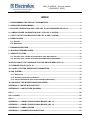
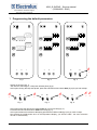
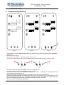
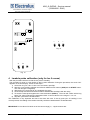
PROJECT ONE OVENS – Service Manual (593804600 - ENG) Electrolux Professional S.p.A. Ovens Platform Customer Support Technical Training & Service ELECTROLUX – ZANUSSI - ALPENINOX PROJECT ONE OVENS - Service manual - CONTENTS: This document contains the information about parameters that can be read and/or modified by means of user interface, service utilities, .... PROJECT REF: ONE ovens AUTHORS: F. Ornella CONTRIBUTION BY: S.Gant DOCUMENT HISTORY: Rel. 01 Date: 26/11/2008 File: Author: Note: AOS ONE Service Manual ENG (01) F.Ornella Lambda sensor management, general update File: AOS ONE service manual (ENG).01.doc ©Copyright 2007 by Electrolux Professional P.1/31 Electrolux Professional S.p.A. Ovens Platform Customer Support Technical Training & Service AOS_Q OVENS – Service manual (593804600 - ENG) INDEX 1 PROGRAMMING THE DEFAULT PARAMETERS ......................................................................4 2 ADVANCED PROGRAMMING.....................................................................................................5 3 BY-PASS CALIBRATION (ONLY FOR LEV. B, NOT REQUIRED ON LEV.C)...........................6 4 LAMBDA PROBE CALIBRATION (ONLY FOR LEV. A OVENS) ...............................................7 5 CAVITY OFFSET CALIBRATION (FOR LEV. A AND C OVENS)...............................................8 6 ERROR CODES............................................................................................................................8 6.1 ERRORS ..................................................................................................................................8 6.2 WARNINGS...............................................................................................................................9 7 FIRMWARE RELEASE.................................................................................................................9 8 WORKING TEMPERATURES......................................................................................................9 9 SERVICE UTILITIES...................................................................................................................10 9.1 UTILITIES THAT CAN BE ACTIVATED WITH OVEN SWITCHED ON..................................................10 9.2 UTILITIES THAT CAN BE ACTIVATED IN PARAMETER PROGRAMMING ..........................................11 10 SELECTION OF THE LANGUAGE FOR THE RECIPE MENU (LEV. A) ..................................11 11 CLEANING CYCLES (LEV. A) ...................................................................................................12 12 CYCLES, UTILITIES, IMPORTANT PARAMETERS .................................................................12 13 GAS SYSTEM.............................................................................................................................13 13.1 GAS VALVE ..........................................................................................................................15 13.2 OFFESET PRESSURE CALIBRATION .......................................................................................16 13.3 USE OF MANOMETER (FOR OFFSET PRESSURE MEASURE)......................................................17 14 CHANGE OF THE MICROPROCESSOR BOARD ....................................................................18 APPENDIX A – WATER BOILING POINT ......................................................................................19 APPENDIX B – CONTACTORS DIAGRAM ...................................................................................20 LEV. C .............................................................................................................................................20 LEV. A AND B .................................................................................................................................20 LEV. C .............................................................................................................................................20 APPENDIX C – CONNECTIONS ON MAIN BOARD (LEV. A).......................................................20 APPENDIX C – CONNECTIONS ON MAIN BOARD (LEV. A).......................................................21 APPENDIX D – LAMBDA PROBE..................................................................................................24 APPENDIX E – PARAMETER DESCRIPTIONS ............................................................................25 File: AOS ONE service manual (ENG).01.doc ©Copyright 2007 by Electrolux Professional P.2/31 Electrolux Professional S.p.A. Ovens Platform Customer Support Technical Training & Service AOS_Q OVENS – Service manual (593804600 - ENG) APPENDIX F – WATER TREATMENT ...........................................................................................27 APPENDIX G – CONNECTION TO HACCP SYSTEM ...................................................................29 APPENDIX H – RELAY DESCRIPTIONS .......................................................................................30 File: AOS ONE service manual (ENG).01.doc ©Copyright 2007 by Electrolux Professional P.3/31 AOS_Q OVENS – Service manual (593804600 - ENG) Electrolux Professional S.p.A. Ovens Platform Customer Support Technical Training & Service 1 Programming the default parameters A B C A B C A C 1 Fig. 2 Fig. 1 Fig. 3 Switch on the oven (fig. 1). Just after the switching on, a lamp test will take place (fig 2). At this point, during the lamp test phase, press the external service buttons A&C (fig.3) till you hear a beep. B 1 C A B 1 Fig. 4 B 1 Fig. 5 1 Fig. 6 At this point press the right service buttons B&C till you hear a beep (fig. 4). Press then the left service buttons A&B till the beep (fig. 5). At this point release the left button A keeping pressed the middle one B (fig. 6) till you hear 2 beeps. Now release the middle button and, on the temperature display, you will see “PdEF”: the oven will switch off and on automatically. File: AOS ONE service manual (ENG).01.doc ©Copyright 2007 by Electrolux Professional P.4/31 2 AOS_Q OVENS – Service manual (593804600 - ENG) Electrolux Professional S.p.A. Ovens Platform Customer Support Technical Training & Service 2 Advanced programming A B C A Fig. 7 B C A Fig. 8 C 1 Fig. 9 The procedure to enter in advanced programming is similar to the procedure for programming the defaults parameters. Switch on the oven (fig. 7). Just after the switching on, a lamp test will take place (fig. 8). At this point, during the lamp test, press the external service buttons A&C (fig.9) till you hear a beep. B 1 C A B 1 Fig. 10 1 Fig. 11 At this point press the right buttons B&C till you hear a beep (fig. 10). Press then the left service buttons A&B till the beep (fig. 11). Release the buttons and on the temperature display you will see “P 1” while on the little display the name of the parameter will appear (fig. 12). With the external service buttons (A or C) it is possible to scroll the list of the parameters. Pressing the middle button B it is possible to see the value of the parameter (fig. 13) and pressing at this point the external buttons (A or C) it is possible to modify the value. Press again the middle button B to return to the displaying of the number of the parameter and to store the new value. Switch off the oven to exit from programming. File: AOS ONE service manual (ENG).01.doc ©Copyright 2007 by Electrolux Professional P.5/31 Electrolux Professional S.p.A. Ovens Platform Customer Support Technical Training & Service A B AOS_Q OVENS – Service manual (593804600 - ENG) C Fig. 12 B Fig. 13 3 By-pass calibration (only for lev. B, not required on lev.C) In order to calibrate the by-pass probe on lev. B ovens. Follow these steps (During the procedure, the word “CAL” appears on the time display): 1) Switch on the oven 2) Enter in parameter programming and set parameters cort and OCA1 to 0 3) Exit from programming and switch on again the oven 4) Select a steam cycle (100 °C) 5) Select continuous time (indication “cont” on time display) 6) Press and hold down the left service buttons (A&B) and then press the START button (fig. 14); the oven will give a long beep. 7) Release the three buttons and wait for the preheating of the boiler. Then wait for the stabilization of the temperature reading by the by-pass probe (check at intervals the by-pass temperature pressing the buttons A&B) 8) When the temperature has stabilized, press the three service buttons (A&B&C) together in order to memorize the value (fig. 15); the oven will confirm the storing with a long beep 9) Allow the oven to work for several minutes in steam mode checking the oven cavity temperature, which should stabilize at the water boiling point. If this reading is greater or less than the correct water boiling point 1 , a corrective value can be stored in the parameter OCA1. Pushing the 3 service buttons to store the bypass temperature, the microprocessor will calculate and store also the value of OCA1. 10) Set parameter cort to 1. 11) Set the altitude above sea level of the site on parameter SEAL TPF TP 1 PT FPT See Appendix A File: AOS ONE service manual (ENG).01.doc ©Copyright 2007 by Electrolux Professional P.6/31 Electrolux Professional S.p.A. Ovens Platform Customer Support Technical Training & Service AOS_Q OVENS – Service manual (593804600 - ENG) A B C Fig. 15 A B Fig. 14 4 Lambda probe calibration (only for lev. A ovens) With this procedure we have to find the 0% point of humidity. The procedure is done in a way similar to the by-pass calibration. During the procedure, the word “CAL” appears on the time display. These are the steps: 1) Set an hot air cycle, 160 °C, time over 15 minutes, open flap; 2) Start the cycle pressing together the left and middle service buttons (A&B)and the START button. The oven will give a long beep; 3) Wait around 10-15 minutes to dry completely the cavity; 4) Close the flap and wait around 20 seconds to stabilize the humidity inside the cavity; 5) To store the value press together the 3 service buttons (A&B&C). The oven will confirm with a long beep. The value is stored in the parameter OLbd. A correct value is in the range of -5 to -75. 6) Stop the cycle with the START button. This calibration is very important and has to be done with care. If the dry point (0% of humidity) is not correctly stored, the reading of the relative humidity could be overestimated or underestimated. IMPORTANT: If the value of OLbd is out of the correct range [-5 ; -75] the reasons are: File: AOS ONE service manual (ENG).01.doc ©Copyright 2007 by Electrolux Professional P.7/31 Electrolux Professional S.p.A. Ovens Platform Customer Support Technical Training & Service AOS_Q OVENS – Service manual (593804600 - ENG) 1. The calibration was not done correctly. The cavity was not completely dry. Do it again. 2. An electric/electronic problem. Please verify the follow: • • • • • • 230V AC at the input of the lambda switching feeder approximately 9.5V DC at the feeder’s output approximately 9.5V DC at the lambda input (if not, verify the cable integrity) an output from the lambda in the range of [-50mV ; -1200mV] depending on the % of humidity in the cooking chamber same value at the PCB input (connector X23). If there is no signal please verify the cable integrity if the above conditions are respected and the value stored in the parameter OLbd is still out of the correct range, the problem is in the PCB. 5 Cavity offset calibration (for lev. A and C ovens) In order to adjust the offset of the cavity probe, enter in parameter programming and set parameters cort and OCA1 to 0. Then run a steam cycle for several minutes and check the cavity temperature, which should stabilize at the water boiling point. If the stabilized cavity temperature is less or greater than the correct water boiling point 2 , a corrective value can be stored in parameter OCA1. After this, set parameter cort to 1and set parameter SEAL (altitude above sea level). TPF FPT 6 Error codes Errors can be divided into 2 categories: errors (they stop the appliance) and warnings (they do not stop the appliance). 6.1 Errors EE2P: Communication error with the EEPROM E---: If the controller detects one or more parameters which have values not permitting the minimum operational requirements, an error code will appear on the display, i.e. “E---” followed by the parameter number. Enter the programming mode and set the correct value according to the parameter list. EtUC: Cavity over temperature; cavity temperature exceeded value stored in parameter cot. EtUB: Boiler over temperature; boiler temperature exceeded value stored in parameter bot. EFUN UP/DOWN: Activation of the thermal protection of the motor. On the little temperature display it will appear “UP” or “DOWN” according it is the thermal protection of the upper motor (and the motor of 6-10 grid ovens) or lower motor on 20-grid oven. The thermal protection has an automatic reset but in order to continue with the cooking process, parameter ALFn has to be reset to 0. Etc: Tripping out of cavity limiter Etb: Tripping out of boiler limiter ESCH: Over temperature on the electronic board; check the cooling fan and the ventilation openings on the bottom of the control panel. Ept1: cavity probe in open circuit (only the steam cycle – 100 °C can be selected) Ept2: boiler probe in open circuit (only hot air cycle can be selected) Ept3: meat probe in open circuit (only time cooking can be selected) Ept4: by-pass probe in open circuit (only hot air, regeneration or low temperature steam cycle can be selected) Ept8: NTC probe in short or open circuit ECAD: Analogic/Digital converters not working (thermocouples input signal) Ertc : No communication with the clock. On lev. C set parameter Ertc to zero E PM: Communication error with PWM system (only gas versions) E SL: Water level probe error (probes in short circuit). If the boiler heating elements or burners are on for a time over that one defined in parameter tbon without a water charging phase, this error message is activated. To reset it, parameter ALFn has to be reset to 0. TP 2 PT See Appendix A File: AOS ONE service manual (ENG).01.doc ©Copyright 2007 by Electrolux Professional P.8/31 Electrolux Professional S.p.A. Ovens Platform Customer Support Technical Training & Service AOS_Q OVENS – Service manual (593804600 - ENG) burn CAUP: Lockout of cavity burner (gas oven) (the upper one in the 20 grid ovens) burn CAdo: Lockout of lower cavity burner (gas oven) in 20 1/1 and 2/1 ovens burn boUP: Lockout of boiler burner (gas oven) (the upper one in 20 2/1 ovens) burn bodo: Lockout of lower boiler burner (gas oven) 6.2 Warnings EH2O: Before the starting of the cleaning system and during its working, there are some check points of the water pressure. If the water pressure is too low this warning message appears on the display. Check the water pressure (1.5÷2.5 bar), check the correct working of the water pressure switch, check if there are obstructions on the cleaning water inlet pipe (its inner diameter must be 20 mm). EFLP: Cavity ventilation flap failure; check the motoreducer or the micro switch that detects the close position of the flap.If the motoreducer does not close the flap within the time set in the firmware (40 sec), the error appears. ELMb: lambda system error. The signal from the lambda probe is out of the range [-50mV ; 1200mV] ECLO: Clock error, it appears if the clock was never adjusted or the battery is discharged EPrG: Error in reading the phases of a multiphase recipe EIND: Error in reading the index of the recipes EDES: Error in reading the description of a recipe ERAM: Communication error with the RAM nFIP: Communication error of recipe display FILL: Safety level probe of the boiler out of water PrEH: Preheating phase of the boiler; it indicates the preheating phase of the cavity if the warning message appears on temperature display. OPEN: boiler drain activated COOL: Cavity cooling phase dEt: low level of detergent rAI: low level of rinser rCLN: request for a cleaning cycle (manual or automatic);parameter FCLn is set to a value different from 0. 7 Firmware release In order to check the version of the firmware, switch on the oven and wait for the lamp test and the end of the start-up phase (4 lines on the temperature display). When on the temperature display, the actual cavity temperature appears, pressing the three service buttons together on the display temperature the firmware version will appear. Pressing again these buttons, the board temperature will be displayed. 8 Working temperatures While the oven is working, it is possible to see the temperature of the several probes pressing the service buttons. See the following figures: Fig. 16 Boiler temperature “tbol” on the display Fig. 18 Meat probe temperature “tPrb” on the display Fig. 17 By-pass temperature “tbyp” on the display Fig. 19 PCB temperature “tntc” on the display File: AOS ONE service manual (ENG).01.doc ©Copyright 2007 by Electrolux Professional P.9/31 Electrolux Professional S.p.A. Ovens Platform Customer Support Technical Training & Service AOS_Q OVENS – Service manual (593804600 - ENG) 9 Service utilities These utilities can be divided in 2 sets: utilities that can be activated with the oven switched on, utilities that can be activated with the oven in parameter programming 9.1 Utilities that can be activated with oven switched on With the oven switched on and not in a cooking phase, pressing simultaneously the following buttons it is possible to activate the detergent, rinse pumps and water valve of the cleaning system: • Combi cycle, temperature buttons (fig. 20): activation of detergent pump (tdEt appears on time display) • Combi cycle, time buttons (fig. 21): activation of rinser pump (trAI appears) • Combi cycle, utility buttons (fig. 22): activation of water valve of the cleaning system (H200 appears at the beginning with pressure switch in open circuit, H201 with closed circuit and water flowing at sufficient pressure) These routines are achievable only on lev. A and lev. C ovens, i.e. with the parameter dCLn set to 0, closed door and cavity temperature less than 80 °C and with the oven not blocked with password. tdEt Fig. 20 DETERGENT PUMP trAI Fig. 21 RINSE PUMP File: AOS ONE service manual (ENG).01.doc ©Copyright 2007 by Electrolux Professional H20n Fig. 22 WATER VALVE P.10/31 Electrolux Professional S.p.A. Ovens Platform Customer Support Technical Training & Service 9.2 • • • AOS_Q OVENS – Service manual (593804600 - ENG) Utilities that can be activated in parameter programming Pressing the steam cycle and hot air cycle buttons(lev. A and lev.B) or pressing Phase and Start button (on lev. B and lev. C), all the output relays are sequentially activated and on the time display it will be displayed the activated relay with the message do1, do2, . (dox=RLx on the EWD). See APPENDIX H. o The steam cycle or phase button acts as main switch: if it is released, the test stops. o Each time the hot air cycle or start button is pressed, the next relay is activated and remains activated till the next pressure of the hot air cycle or start button. o If the hot air cycle or start button is kept pressed, the relays are sequentially activated. Pressing the time buttons, the time will be displayed Pressing the utility button, on the time display a 4-characters message will be displayed while on the little display will be shown a number with the following meanings Big display ntc Prb1 Prb2 Prb3 Prb4 Prb5 Prb6 CEL1 CEL2 boL1 boL2 byP Prb HuM Meaning of the number on the little display PCB temperature First meat probe temperature (lev. A) Second meat probe temperature (lev. A) Third meat probe temperature (lev. A) Fourth meat probe temperature (lev. A) Fifth meat probe temperature (lev. A) Sixth meat probe temperature (lev. A) First cavity temperature Second cavity temperature First boiler probe Second boiler probe Bypass probe Single-point meat probe (lev. B) KS contactor is activated for 15 s and the lambda probe is fed and after a while the cavity humidity will be displayed If one of the probes is detecting the same temperature of the ntc probe (PCB temperature), the meanings are the following: 1) Probe in short circuit 2) Probe not connected (for example Prb on a lev. A oven) 3) Probe at the same temperature of the ntc probe • • • • • Pressing the temperature button a lamp test is activated If the word “HOLD” in the utility section is green it means the door microswitch is in closed position If the word “HACCP” in the utility section is green it means the cavity flap microswitch is closed If the led “open door” is switched on in parameter programming mode, it means that the safety level probe of the boiler is detecting water If the led “scale alarm” is switched on in parameter programming mode, it means that the working level probe of the boiler is detecting water 10 Selection of the language for the recipe menu (lev. A) It is possible to select a language for the menu of the recipes. To select the language, set parameter LanG to the correct value for the desired language (see the relevant parameter list). File: AOS ONE service manual (ENG).01.doc ©Copyright 2007 by Electrolux Professional P.11/31 Electrolux Professional S.p.A. Ovens Platform Customer Support Technical Training & Service AOS_Q OVENS – Service manual (593804600 - ENG) 11 Cleaning cycles (lev. A) Each cleaning cycle can be divided into the repeating of 3 fundamental phases 3 : Phase A - Washing phase controlled through the parameters CLt1 (time of detergent injection) and CLt2 (time of detergent + water injection) Phase C - Rinsing and drying phase controlled through the parameters CLt3 (time of rinse aid injection) and CLt4 (time of water injection) TPF FPT The cleaning cycles are composed according to the following table: Cycle SOFT CYCLE MEDIUM CYCLE STRONG CYCLE EXTRA–STRONG CYCLE Name of the program CLEAN 1/SOFT CLEAN 2/MEDIUM CLEAN 3/STRONG CLEAN 4/X-STRONG Composition of the phases A+C 2A+C 4A+C 6A+C At the end of a cleaning cycle (at the end of the acoustic signal) the oven enter in a stand-by state, i.e. the user interface shows only the time and the ON-OFF button led is the only lit up led. The exit from this standby state takes place with an action from the user: pressing of a button of the user interface or opening the oven door. NB: To check the correct water installation, make sure the rotating wash arm does not turn below 100 rpm (120 rpm max.) 12 Cycles, utilities, important parameters Hot air cycle(Lev. A, B, C): Only the cavity heating elements/burners are working. The maximum temperature is 300 °C; if the set point is over 250 °C, the maximum working time that can be set is given by parameter dutM. If on a lev. A oven a humidity value is set, the lambda probe will control only the cavity flap. Steam cycle(Lev.A, B): The maximum set point temperature is 100 °C (130 °C from firmware 2.6). Boiler heating elements/burners are controlled with the lambda probe (lev. A ovens) or with the by-pass probe (lev. B ovens) for a set point of 100 °C; for set point lower than 100 °C, the boiler is controlled with the cavity probe. If the set temperature is over 100 °C, also the cavity heating elements/burners are switched on. Combi cycle(Lev.A, B, C): Boiler and cavity heating elements/burners are working (Lev. A, B). Cavity heating elements/burners are controlled with the cavity probe (Lev.A,B,C); boiler heating elements/burners are controlled by the lambda probe (lev. A ovens) or by the by-pass probe (lev. B ovens). In the Lev.C water is sprayed directly in the cavity fan with the umidifier. The maximum set point is 250 °C. From firmware 2.6, for a set point lower than 100 °C, to obtain the required steam the humidifier is used (not the boiler). Regeneration cycle: In this cycle boiler and cavity heating elements/burners work alternatively during the first rising till the set point is reached. After the set point is reached, boiler and cavity works in parallel to maintain temperature and humidity. DELTA-COOKING cycle: This cooking cycle is used with the meat probe and hot air, steam or combi cycle. For this cycle it is set a Delta temperature (let’s call it Δ) and not a cavity set-point. The cavity will be thermostatically controlled to have in any moment a cavity temperature that is Δ °C over the meat probe temperature. COOL: The cavity-cooling mode takes place with the fan running and water injection from the temperature of 180 °C (parameter trMA) to the temperature of 40 °C (parameter trMn). Passing from a cooking cycle to a steam cycle, an automatic cooling phase will take place if the cavity temperature is over the set point of the steam cycle. Boiler automatic drain: The automatic boiler drain takes place each 15 minutes of working of the boiler heating elements/burners (parameter dbon in quarter of hour) and if the water temperature is lower than 50 °C (parameter tcdb). Then the boiler is automatically filled Board cooling: The cooling fan is activated starting from the temperature defined in parameter Sbc. 3 At the beginning of each phase the cavity is brought at a certain temperature with a COOLING phase without water or with an hot air cycle TP PT File: AOS ONE service manual (ENG).01.doc ©Copyright 2007 by Electrolux Professional P.12/31 Electrolux Professional S.p.A. Ovens Platform Customer Support Technical Training & Service AOS_Q OVENS – Service manual (593804600 - ENG) Boiler preheating: After the filling of the boiler, the water is heated up to 85 °C (parameter SPHb) and maintained at this temperature if the boiler is not used (if the preheating is enabled i.e. if parameter dSPS is set to 1). Hour counters: The hour counter parameters are the following: hbol: boiler quarter of hour counter from the latest draining (automatic or manual) hAir: hot air mode hour counter hStM: steam mode hour counter hcMb: combi mode hour counter Parameter PPM: Setting this parameter to 1, the Energy Optimiser function is enabled (with Sicotronic system) in the foreseen electric ovens. The 2 high voltage digital inputs named IND4 (X10-11/5) and IND5 (X10-11/6) and the 2 output relays RL5 and RL24 are used. RL5 is closed each time the oven has to use the heating elements at half or full power while RL24 is closed when the heating elements have to be used at full power (independently from Sicotronic system). IND4 and IND5 are the high voltage inputs of the commands from Sicotronic system: if on IND4 and IND5 are present 230V the oven is working normally; if only one is at 230V the oven is forced from Sicotronic system to work at half power (with no visualization on the display); if both IND4 and IND5 are at 0V, the oven is forced to cut all the heating elements Parameter dEMO: If enabled (set to 1), this parameter makes the oven working in demo function i.e. the user interface is fully working but the oven does not make any real function (no load is activated). Parameter tbon: Timeout for E SL error; if it is set to 0 the control is disabled (from firmware 2.80). Parameter AbSP: Setting this parameter to 1, the selected cooking cycle starts closing the door without pressing the START/STOP button. Parameter dSPS: Setting this parameter to 1 the pre-heating of the boiler is disabled when the oven is not in cooking mode, so the pre-heating will start at the beginning of a combi or steam mode or of a recipe that provided the use of those modes in one of its steps. 13 Gas system File: AOS ONE service manual (ENG).01.doc ©Copyright 2007 by Electrolux Professional P.13/31 Electrolux Professional S.p.A. Ovens Platform Customer Support Technical Training & Service AOS_Q OVENS – Service manual (593804600 - ENG) The gas system is made with CO and NOx low emission burner. The main components are the following: gas valve from SIT type SIGMA 848 AC burner blower that is intaking air through a calibrated mixer where the air–gas mixture is created; then the fun conveys the mixture to the burner A cavity and a boiler heat exchanger made with a corrugated tube for increasing the efficiency An ignition rod and a detection rod A flame control device An external igniter Starting a cooking cycle, the POW board of the oven activates the flame control device and the burner fan whose speed is controlled with a PWM signal. The POW board activates the flame control device. From pin 8 of this device a high voltage output (230 Vac) is carried to the relevant burner fan and to the high voltage digital input section of the POW board (X10/5÷8). With an high voltage input on X10/5÷8, the POW board generates on X9/2÷5 a PWM signal to control the speed of the burner fans (a signal that defines the rotating speed of he fan and so the quantity of sucked air and gas) and the 12 Vdc on X9/1 to feed the inner board of the burner fan. The PWM signal changes according to the status of the burner, i.e.: Start of the burner: controlled with parameters StcA (start of cavity burners) and Stbo (start of boiler burners). Full power of the burner: controlled with parameters FucA (full power of cavity burners) and Fubo (full power of boiler burners) Half power of the burner: controlled with parameters hAcA (half power of cavity burners) and hAbo (half power of boiler burners) The quantity of sucked gas is controlled with those parameters (which are determining the speed of the burner fans), with the injector/diaphragm inserted at the outlet of the gas valve and with the calibration of the offset value on the gas valve. The quantity of sucked air is controlled with the above parameters and with the calibrated aerator on the mixer. The ignition sequence is then the following: • The POWER board activates the flame control device • After 1.5 s, the control device activates the fan that start at the speed determined with parameters Stxx • The flame control device activates the external igniter through pin 14, the igniter generates the spark for 2s and after these, there are 2 s for flame detection • If the flame is detected, the start speed is maintained for around 10 s and after this time the fans are carried to their working speed (half or full power) • If the flame is not detected, the fan keep on running for an inter purge phase of 15 s; after this phase there is a stop of the fan for 1 s and the ignition sequence is repeated. If the flame is still not detected there will be again 15 s of purging phase and this for five times before the lockout signal. In case of loosening of the flame signal during working, only one re-ignition attempts takes place. So if the burner fan is off for at least 0.5 s (the fan is controlled from the flame control device through the 230Vac signal form pin 8), the POW board deduces that the flame control device is going to try again an ignition sequence and then goes back to the beginning of the ignition sequence. If on the contrary the burner fan is off for at least 5 s, the POW board deduces that the flame control device is in lockout. In case of conversion to different type of gas, besides the injector/diaphragm also the parameters, which control the PWM signal, and the offset pressure calibration have to be changed according to the gas calibration table NB: In case of changing from natural gas to LPG or G30 in some models, the fan flange (fig. 24) has to be changed; these changes has to be made in • CAVITY burner of 10 2/1 e 20 2/1 ovens • BOILER burner of 10 1/1, 10 2/1 e 20 1/1 ovens File: AOS ONE service manual (ENG).01.doc ©Copyright 2007 by Electrolux Professional P.14/31 Electrolux Professional S.p.A. Ovens Platform Customer Support Technical Training & Service AOS_Q OVENS – Service manual (593804600 - ENG) 13.1 Gas valve Injector Remove this threaded cap to get access to the offset adjustment screw Offset pressure test point Inlet pressure test point File: AOS ONE service manual (ENG).01.doc ©Copyright 2007 by Electrolux Professional P.15/31 AOS_Q OVENS – Service manual (593804600 - ENG) Electrolux Professional S.p.A. Ovens Platform Customer Support Technical Training & Service - + Offset adjustment screw Offset pressure test point Fig. 23 - Injector Fig. 24 – burner flange 13.2 Offeset pressure calibration For the adjustment of the offset pressure, connect a manometer with a resolution of 1 Pa (100 Pa=1 mbar) to the offset pressure test point after loosening the sealing screw. To adjust the cavity gas valve offset, set a hot air cycle, half power; to adjust the boiler gas valve offset select a steam cycle, half power. Wait around 3 minutes for the stabilization of the pressure before adjusting it turning slowly the screw indicated in the picture above. File: AOS ONE service manual (ENG).01.doc ©Copyright 2007 by Electrolux Professional P.16/31 Electrolux Professional S.p.A. Ovens Platform Customer Support Technical Training & Service AOS_Q OVENS – Service manual (593804600 - ENG) 13.3 Use of manometer (for offset pressure measure) Fig. 26 - Manometer 0S0388 Using the pressure inlet signed with “+” and with negative reading on the display as in the fig. 27-28, this means we are measuring – 0.16 hPa = – 16 Pa: Fig. 27 Fig. 28 Using the pressure inlet signed with “+” and with positive reading on the display as in the fig. 29-30, this means we are measuring + 0.16 hPa = + 16 Pa: Fig. 29 Fig. 30 Using the pressure inlet signed with “–” and with negative reading on the display as in the fig.31-32, this means we are measuring + 0.16 hPa = + 16 Pa: File: AOS ONE service manual (ENG).01.doc ©Copyright 2007 by Electrolux Professional P.17/31 Electrolux Professional S.p.A. Ovens Platform Customer Support Technical Training & Service AOS_Q OVENS – Service manual (593804600 - ENG) Fig. 31 Fig. 32 Using the pressure inlet signed with “–” and with positive reading on the display as in the fig. 33-34, this means we are measuring – 0.16 hPa = – 16 Pa: Fig. 33 Fig. 34 14 Change of the microprocessor board In case of changing of the microprocessor board, the following operations/calibrations have to be done: 1) Default parameter programming 2) Change parameters according to the parameter list 3) Lambda probe calibration for lev. A ovens 4) By-pass calibration (lev. B ovens) and cavity offset (parameter OCA1), or only cavity offset for lev. A and C ovens. File: AOS ONE service manual (ENG).01.doc ©Copyright 2007 by Electrolux Professional P.18/31 AOS_Q OVENS – Service manual (593804600 - ENG) Electrolux Professional S.p.A. Ovens Platform Customer Support Technical Training & Service APPENDIX A – WATER BOILING POINT Height (m) 0 300 500 800 1000 1500 2000 Water boiling point (°C) 100.00 98.90 98.30 97.50 96.80 95.00 93.50 File: AOS ONE service manual (ENG).01.doc ©Copyright 2007 by Electrolux Professional P.19/31 AOS_Q OVENS – Service manual (593804600 - ENG) Electrolux Professional S.p.A. Ovens Platform Customer Support Technical Training & Service APPENDIX B – CONTACTORS DIAGRAM LEV. A and B C o n ta c to rs u s e d o n 0 6 1 E _ ,1 0 1 E _ ,1 0 2 E 100% 1 /2 H O T A IR 100% 1 /2 COMBI 100% 1 /2 STEAM KS K1 K2 K3 K4 KS K1 K2 K3 K4 KS K1 K2 K3 K4 LEV. C C o n ta c to rs u s e d o n 0 6 1 E _ ,1 0 1 E _ ,1 0 2 E 100% 1 /2 H O T A IR & COMBI KS K1 K2 K3 K4 LEV. A and B C o n ta c to rs u s e d o n 2 0 1 E _ , 2 0 2 E _ 100% 1 /2 H O T A IR 100% 1 /2 COMBI 100% 1 /2 STEAM KS K1 K2 K3 K4 K5 K6 K7 K8 KS K1 K2 K3 K4 K5 K6 K7 K8 KS K1 K2 K3 K4 K5 K6 K7 K8 LEV. C C o n ta c to rs u s e d o n 2 0 1 E _ ,2 0 2 E 100% 1/2 H O T A IR & COM B I KS K1 K2 K3 K4 K5 K6 K7 K8 File: AOS ONE service manual (ENG).01.doc ©Copyright 2007 by Electrolux Professional P.20/31 Electrolux Professional S.p.A. Ovens Platform Customer Support Technical Training & Service AOS_Q OVENS – Service manual (593804600 - ENG) APPENDIX C – CONNECTIONS ON MAIN BOARD (Lev. A) X20 X21 X22 X23 X18 X19 X15 X16 X17 X14 Put a jumper to make a short in the not used connections. File: AOS ONE service manual (ENG).01.doc ©Copyright 2007 by Electrolux Professional P.21/31 AOS_Q OVENS – Service manual (593804600 - ENG) Electrolux Professional S.p.A. Ovens Platform Customer Support Technical Training & Service X1-1 X10/11-1 X25/26-1 X24-1 X28-1 X12/13-1 X9-1 X2/3-1 X4/5-1 X8-1 X6/7-1 File: AOS ONE service manual (ENG).01.doc ©Copyright 2007 by Electrolux Professional P.22/31 Electrolux Professional S.p.A. Ovens Platform Customer Support Technical Training & Service Connector X1 X2/3 X4/5 X6/7 X8 X9 X10/11 X12/13 X14 X15 X16 X17 X18 X19 X20, X21, X22 X23 X25/26 X28 AOS_Q OVENS – Service manual (593804600 - ENG) Description Main board supply (24 Vac) Power supply to cavity fan motors, cooling fans, cavity flap motor, switching feeder for the lambda probe Power supply to coils of cavity/boiler heating element contactors or cavity/boiler burner gas valves, steam condensing valve, humidifier valve, cavity lamps Power supply to boiler water filling valves, boiler drain valve Power supply to cleaning system Output of PWM signal and 12 Vdc for burner fans High voltage digital input, i.e. thermal protection of the cavity fan motors and command signal of the burner fans from the ignition devices Low voltage digital input, i.e. cleaning system water pressure switch, cavity limiter, boiler limiter, door micro switch and micro switch of the cavity flap Connection of bypass probe Connection of cavity probe Connection of boiler probe Connection of single point meat probe Connection of second cavity probe Connection of second boiler probe Connections of multi point probe Connection of lambda probe Connections of water level probes RS485 connection File: AOS ONE service manual (ENG).01.doc ©Copyright 2007 by Electrolux Professional P.23/31 Electrolux Professional S.p.A. Ovens Platform Customer Support Technical Training & Service AOS_Q OVENS – Service manual (593804600 - ENG) APPENDIX D – LAMBDA PROBE In the lev. A ovens the lambda probe is used to measure the humidity. How does it work? The lambda probe permits measurement of oxygen concentration through a solid electrolyte (ceramic element) The ceramic part of the probe is in the form of a tube closed at one end. The inside and outside surfaces of the ceramic sensor have a microporous platinum layer (electrode). The platinum layer, which is in contact with the analyzed gas, is covered with a highly porous protective ceramic layer. The ceramic sensor (ZrOB2 – solid electrolyte) is heated from inside by means of a ceramic heater so that the temperature of the sensor ceramic remains above 350 °C. Starting from 300°C, the ZrOB2B sensor becomes conductive for the oxygen ions so that if there is a different concentration of oxygen at the two sides of the sensors (one side is in contact with the analyzed gas, the other side is in contact with the external), a voltage is generated. Since the Oxygen/Nitrogen ratio in the air is constant, a measurement of the concentration of oxygen enables the percentage of a third gas (in this case water vapor) to be determined. In fact the addition of a third gas to a sample of air has the effect of reducing in a proportional manner the presence of oxygen and nitrogen so that, as said, determining the relative concentration of oxygen allows the amount of the third introduced gas of the mixture to be determined (see the diagram). 1 2 3 4 5 100 90 80 water 70 60 50 40 nitrogen 30 20 10 oxygen 0 0 10 20 30 40 50 60 70 80 90 100 water percentage Connections on the lambda probe: Pin 1: not used Pin 2-3: connections to the main board (connector X23) Pin 4-5: connections to the switching feeder File: AOS ONE service manual (ENG).01.doc ©Copyright 2007 by Electrolux Professional P.24/31 Electrolux Professional S.p.A. Ovens Platform Customer Support Technical Training & Service AOS_Q OVENS – Service manual (593804600 - ENG) APPENDIX E – PARAMETER DESCRIPTIONS Nome 6Prb Descrizione Presence of 6-point meat probe (1=yes for lev. A, 0 for lev. B) AbLP Flag to enable only the half power mode in the gas version (0=disable; 1= enable) AbSP AbtF Addr Flag to enable starting of cooking closing the door (0=disable; 1=enable) Flag to enable the by-pass probe (0=disabled ; 1=enabled) RS485 address Flag to enable detergent/rinser level probes (0=disable; 1=enable) when the relevant sensors are installed Activation of cavity motor thermal protection Level of the oven Type of oven RS485 bit rate Max. steam generator overheating (ETUB alarm) First character of the password Second character of the password Third character of the password Fourth character of the password Fifth character of the password Sixth character of the password Seventh character of the password Eighth character of the password Length of detergent injection (phase A) Length of detergent+water injection (phase A) Length of rinser+water injection (phase C) Length of water injection (phase C) Flag to enable cavity temperature displaying adjustment Max. cooking chamber overheating (ETUC alarm) Delay for boiler drain Flag to disable automatic cleaning cycles (1=disable) Flag to enable automatic cleaning cycles from “utility” button (0=enable; 1=disable) Flag to enable DEMO (0=disable; 1=enable) Flag to disable the oven stops when door is open in convection, steam and combi mode: (0=the oven stops) Flag to disable pre-heating of the boiler when the oven is in stand-by mode (0=enable pre-heating; 1=disable) Delay for activation of fast filling during opening of boiler drain valve Maximum length of a phase with cavity temperature over 250 ºC Flag to enable storing/erasing of recipes on EEPROM (0=enable; 1=disable) Temperature for starting time computation of phase 1 during semi-automatic cleaning Presence of motorised cavity flap (1=yes) Flag to enable the RTC real time clock (0=disable; 1= enable) Temperature unit (°F = 1, °C = 0) Start speed of the motor (only for USA gas 2/1 models) 0=start at the selected speed; 1=start at full speed; 2= start at half speed Minimum time to force a cleaning cycle (0=no cleaning cycle) PWM value at full power of boiler burners PWM value at full power of cavity burners Define if the oven is GAS heated (1) or ELECTRIC heated (0) AL1E ALFn APPL APPM bAud bot chr1 chr2 chr3 chr4 chr5 chr6 chr7 chr8 CLt1 CLt2 CLt3 CLt4 cort cot dbon dCLn dCLo dEMO dSod dSPS dtSb dutM E2PP EcLn EnFL Ertc FAHr FAn FCLn Fubo FucA GAS File: AOS ONE service manual (ENG).01.doc ©Copyright 2007 by Electrolux Professional P.25/31 Electrolux Professional S.p.A. Ovens Platform Customer Support Technical Training & Service Nome hAbo HabP hAcA hAir hboL HbYP HCCP hcMb Hdut hHEA hStM Huon LAMb LanG Man nMod OCA1 0lbd PASS PAUT PFAC PPM PrEH Sbc SbYP SEAL SinC SPHb SPHF Stbo StbP StcA StoF Ston tbon tcdb tCMS thMA tPrn trMA trMn AOS_Q OVENS – Service manual (593804600 - ENG) Descrizione PWM value at middle power of boiler burners Steam condenser engagement in "hot air" mode PWM value at middle power of cavity burners Hot air hour counter Boiler hour counter Max humidity value to stop the boiler HACCP Mode Combi hour counter Flag to enable heater duty cycle (0=disable; 1=enable) Delay on burner flame ignition after the start of the cavity motor Steam hour counter ON phase of the humidifier with combi cycle beetween 50 and 100 degrees Presence of lambda probe (1=yes) Language for the menu Flag to enable manual cookings (0=disable; 1=enable) Define if the modification of store program is disable OFFSET of first cavity probe Calibration of the lambda probe (0% of humidity) Flag to enable password (0=disable, 1=enable) Flag to enable special programs, i.e. preheating programs and Low temperature (0=disable; 1=enable) Flag to enable factory preset recipes (0=disable; 1=enable) Flag to enable Peak Power Management (0=disable; 1=enable) Flag to enable cavity preheating during cooking (0=disable; 1=enable) Cooling temperature set for board ventilation Bypass temperature with max. cooking cavity steam temperature (calibration) Altitude above sea level Boiler temperature that detect presence of scale Preheating temperature of the boiler Boiler temperature during leavening PWM value at start of boiler burners Steam condenser engagement in "boiler" mode PWM value at start of cavity burners Minimum time for "switch off" of boiler Minimum time for "switch on" of boiler Timeout for E SL alarm, water level probe alarm Max water temperature for boiler drain Limit of cavity temperature set for working at high temperature Define the max. temperature limit for the manual injection of water Print frequency (0=no print) Define the max. temperature for water injection during cooling phase Define the min. temperature for water injection during cooling phase File: AOS ONE service manual (ENG).01.doc ©Copyright 2007 by Electrolux Professional P.26/31 Electrolux Professional S.p.A. Ovens Platform Customer Support Technical Training & Service AOS_Q OVENS – Service manual (593804600 - ENG) APPENDIX F – WATER TREATMENT File: AOS ONE service manual (ENG).01.doc ©Copyright 2007 by Electrolux Professional P.27/31 AOS_Q OVENS – Service manual (593804600 - ENG) Electrolux Professional S.p.A. Ovens Platform Customer Support Technical Training & Service Summary table: Graph Hardness Treatment Not required < 5°F Not required Not required > 5°F Softener Nanofilter < 5°F Nanofilter Nanofilter >5°F Nanofilter File: AOS ONE service manual (ENG).01.doc ©Copyright 2007 by Electrolux Professional Osmotizer < 5°F Osmotizer Osmotizer > 5°F Osmotizer P.28/31 Electrolux Professional S.p.A. Ovens Platform Customer Support Technical Training & Service AOS_Q OVENS – Service manual (593804600 - ENG) APPENDIX G – CONNECTION TO HACCP SYSTEM TO BE DEFINED File: AOS ONE service manual (ENG).01.doc ©Copyright 2007 by Electrolux Professional P.29/31 Electrolux Professional S.p.A. Ovens Platform Customer Support Technical Training & Service AOS_Q OVENS – Service manual (593804600 - ENG) APPENDIX H – RELAY DESCRIPTIONS ELECTRIC OVENS RL 1/do1 RL 2/do2 RL 3/do3 RL 4/do4 RL 5/do5 RL 6/do6 RL 7/do7 RL 8/do8 RL 9/do9 RL 10/do10 RL 11/do11 RL 12/do12 RL 13/do13 RL 14/do14 RL 15/do15 RL 16/do16 RL 17/do17 RL 18/do18 RL 19/do19 RL 20 /do20 RL 21/do21 RL 22/do22 RL 23/do23 RL 24/do24 FAN MOTOR POWER SUPPLY HALF/FULL SPEED FAN MOTOR COOLING FAN/S SAFETY CONTACTOR (KS OR KS1&KS2) /LAMBDA FEEDER N/A CAVITY VENT VALVE K2/K6 CONTACTOR/S (FOR CAVITY) K4/K8 CONTACTOR/S (FOR BOILER) K1/K5 CONTACTOR/S (FOR CAVITY) K3/K7 CONTACTOR/S (FOR BOILER) CAVITY UMIDIFIER SOLENOID VALVE STEAM CONDENSER SOLENOID VALVE CAVITY LAMPS BOILER SLOW WATER FILLING BOILER FAST WATER FILLING BOILER AUTOMATIC DRAIN VALVE N/A N/A N/A N/A DETERGENT PUMP RINSE PUMP WATER SOLENOID VALVE (CLEANING SYSTEM) N/A File: AOS ONE service manual (ENG).01.doc ©Copyright 2007 by Electrolux Professional P.30/31 Electrolux Professional S.p.A. Ovens Platform Customer Support Technical Training & Service AOS_Q OVENS – Service manual (593804600 - ENG) GAS OVENS RL 1/do1 RL 2/do2 RL 3/do3 RL 4/do4 RL 5/do5 RL 6/do6 RL 7/do7 RL 8/do8 RL 9/do9 RL 10/do10 RL 11/do11 RL 12/do12 RL 13/do13 RL 14/do14 RL 15/do15 RL 16/do16 RL 17/do17 RL 18/do18 RL 19/do19 RL 20/do20 RL 21/do21 RL 22/do22 RL 23/do23 RL 24/do24 FAN MOTOR POWER SUPPLY HALF/FULL SPEED FAN MOTOR COOLING FAN/S LAMBDA SWITCHING FEEDER N/A CAVITY VENT VALVE CAVITY IGNITION DEVICE RESET BOILER IGNITION DEVICE RESET CAVITY IGNITION DEVICE POWER SUPPLY BOILER IGNITION DEVICE POWER SUPPLY CAVITY UMIDIFIER SOLENOID VALVE STEAM CONDENSER SOLENOID VALVE CAVITY LAMPS BOILER SLOW WATER FILLING BOILER FAST WATER FILLING BOILER AUTOMATIC DRAIN VALVE N/A N/A N/A N/A DETERGENT PUMP RINSE PUMP WATER SOLENOID VALVE (CLEANING SYSTEM) N/A File: AOS ONE service manual (ENG).01.doc ©Copyright 2007 by Electrolux Professional P.31/31