1
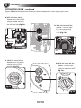
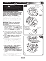
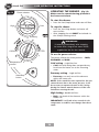
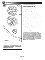
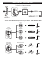
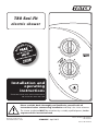
T80 Easi-Fit electric shower Installation and operating instructions Installers please note these instructions are to be left with the user Please read this book thoroughly and familiarise yourself with all instructions before commencing installation and keep it for future reference. The shower installation MUST be carried out by a suitably qualified person, in the sequence of this instruction book. EC Registered Design No. 001902388-0005 to 0007 2180858E - April 2013 Patents Pending:GB 2489547 GB 2495343 Patent:GB 2481878 INTRODUCTION - PLEASE READ PLEASE READ THIS IMPORTANT SAFETY INFORMATION Products manufactured by Triton are safe and without risk provided they are installed, used and maintained in good working order in accordance with our instructions and recommendations. WARNING: DO NOT operate shower if frozen, or suspected of being frozen. It must thaw out before using. DO NOT operate the unit if the showerhead or spray hose becomes damaged. DO NOT restrict flow out of shower by placing showerhead in direct contact with your body. DO NOT operate the shower if water ceases to flow during use or if water has entered inside the unit because of an incorrectly fitted cover. WARNING: If restarting the shower immediately after stopping, be aware that a slug of hot water will be expelled for the first few seconds. This contains all the necessary fitting and operating for your shower. 2.3 instructions DO NOT solder pipes electric or fittings within 300mm 1 book GENERAL of the shower unit, as heat can transfer along 1.1 Isolate the electrical and water supplies before Care taken during the installation will provide a long, trouble-free life from your shower. the pipework and damage components. removing the cover. 2.4 DO NOT fit any form of outlet flow control as 1.2 Read all of these instructions and retain them thecover outletelectric acts asshower a vent for the heater Triton watching the short online *videos that basics beforecan. your for recommend later use. 2.5 DO NOT use excessive force when making installation *(videos risks may not with show the plumbing exact model purchased) 1.3 DO NOT- take or .electrical connections to the flexible hose or showerhead, finger tight is sufficient. 2.6 All plumbing connections must be completed proceeding with the installation. before making the electrical connections. • Electrical requirements for electric showers 1.5 The unit must be mounted onto the finished 2.7 This appliance MUST not be connected to the wall surface (on top of the tiles). DO NOT tile • Plumbing requirements for electric showers inlet supply by a hose-set. up to or seal around ANY PART of the unit • Kilowatt ratings explained using silicone sealer after fixing to the wall. 3 Special care mustvisit: be taken NOT TO BLOCK To view these videos www.tritonshowers.co.uk/triton-products/product-videos.aspx 3.1 The installation must comply with BS 7671 OR SEAL ANY PRD VENTS ON THE UNIT. ‘Requirements for electrical installations’ (IEE 1.6 Contact Customer Service (see back page), if wiring regulations), building regulations or any any of the following occur: particular regulations specified by the local USE THE FOLLOWING TO AID YOURas INSTALLATION a)PLEASE If it is intended to operate the shower at CHECK LIST Electrical Supply Company. pressures above the maximum or below the 3.2 This appliance MUST be earthed. Tick off as you complete minimum stated. 3.3 In accordance with ‘The Plugs and Sockets etc. SECTION b) If the unit shows a distinct change in performance. (Safety) Regulations 1994’, this appliance is1 Check that the water supply will satisfy requirements............................................... c) 1If the shower is frozen. intended to be permanently connected to the 1.7 SECTION If it is intended to operate the shower in areas fixed wiring of the electrical mains system. Check that water200 & cable entry points of the unitMake meetsure requirements...................... tight 2 2of hard water (above ppm temporary 3.4 all electrical connections are to hardness), a scale inhibitor may have to be prevent overheating. SECTION For advice on the Scalesupply Inhibitor, Check that the electric will satisfy requirements............................................. 3 3.5 A 30mA residual current device (RCD) MUST 3fitted. contact Customer Service. be installed in all UK electric and pumped SECTION 1.8 The showerhead must be cleaned regularly shower circuits. This may be part of the of the shower..scale ................................................................................................ 4 4with Siting descalent to remove and debris, consumer unit or a separate unit. otherwise restrictions to the flow on the outlet SECTION 3.6 Switch off immediately at isolating switch if unit will result in higher temperatures installation................................................................................................ 5 water ceases to flow during use. 5of thePlumbing and could also cause the (PRD) Pressure Relief 3.7 Other electrical equipment i.e. extractor fans, SECTION Device in the unit to operate. pumps must not be connected to the circuits 6 1.9 6This Electrical product isinstallation................................................................................................. not suitable for mounting into within the unit. steam rooms or steam cubicles. SECTION 3.8 Switch off at isolating switch when not in use. 7 7 Fit to the wall & connect the shower supplies........................................................... This is a safety procedure recommended with 2 SECTION all electrical appliances. 2.1 The plumbing installation must comply with the cover....................................................................................................... 8 8WaterFitting Regulations, Building Regulations or any 3.9 As with all electrical appliances it is particular regulations as specified by Local SECTION recommended to have the shower and Company or Water the Undertakers Commission shower and in the way described. ............................................ 9 by 9WaterONLY installation checked at least every two years should be in accordance with BS EN 806. a competent electrician to ensure there is no SECTION 2.2 The supply pipe must be flushed to clear debris deterioration due to age and usage. Familiarise yourself theunit. user operating instructions............................................ 10 10before connecting to the with shower equipment. • What an electric shower? 1.4 Isolate is electrical and water supplies before ELECTRICAL PLUMBING 2 DO NOT operate the shower if water ceases to flow during use or if water has entered inside the unit because of an incorrectly fitted cover. WARNING: If restarting the shower immediately after stopping, be aware that a slug of IMPORTANT GENERAL GUIDANCE NOTES hot water will be expelled for the -first few seconds. 1 GENERAL 1.1 Isolate the electrical and water supplies before 2.3 DO NOT solder pipes or fittings within 300mm of the shower unit, as heat can transfer along the pipework and damage components. 2.4 DO NOT fit any form of outlet flow control as the outlet acts as a vent for the heater can. 2.5 DO NOT use excessive force when making connections to the flexible hose or showerhead, finger tight is sufficient. 2.6 All plumbing connections must be completed before making the electrical connections. 2.7 This appliance MUST not be connected to the inlet supply by a hose-set. removing the cover. 1.2 Read all of these instructions and retain them for later use. 1.3 DO NOT take risks with plumbing or electrical equipment. 1.4 Isolate electrical and water supplies before proceeding with the installation. 1.5 The unit must be mounted onto the finished 1.6 a) b) c) 1.7 1.8 1.9 wall surface (on top of the tiles). DO NOT tile up to or seal around ANY PART of the unit using silicone sealer after fixing to the wall. Special care must be taken NOT TO BLOCK OR SEAL ANY PRD VENTS ON THE UNIT. Contact Customer Service (see back page), if any of the following occur: If it is intended to operate the shower at pressures above the maximum or below the minimum stated. If the unit shows a distinct change in performance. If the shower is frozen. If it is intended to operate the shower in areas of hard water (above 200 ppm temporary hardness), a scale inhibitor may have to be fitted. For advice on the Scale Inhibitor, contact Customer Service. The showerhead must be cleaned regularly with descalent to remove scale and debris, otherwise restrictions to the flow on the outlet of the unit will result in higher temperatures and could also cause the (PRD) Pressure Relief Device in the unit to operate. This product is not suitable for mounting into steam rooms or steam cubicles. ELECTRICAL 3 3.1 The installation must comply with BS 7671 ‘Requirements for electrical installations’ (IEE wiring regulations), building regulations or any particular regulations as specified by the local Electrical Supply Company. 3.2 This appliance MUST be earthed. 3.3 In accordance with ‘The Plugs and Sockets etc. (Safety) Regulations 1994’, this appliance is intended to be permanently connected to the fixed wiring of the electrical mains system. 3.4 Make sure all electrical connections are tight to prevent overheating. 3.5 A 30mA residual current device (RCD) MUST be installed in all UK electric and pumped shower circuits. This may be part of the consumer unit or a separate unit. 3.6 Switch off immediately at isolating switch if water ceases to flow during use. 3.7 Other electrical equipment i.e. extractor fans, pumps must not be connected to the circuits within the unit. 3.8 Switch off at isolating switch when not in use. This is a safety procedure recommended with all electrical appliances. PLUMBING 2 2.1 The plumbing installation must comply with Water Regulations, Building Regulations or any particular regulations as specified by Local Water Company or Water Undertakers and should be in accordance with BS EN 806. 2.2 The supply pipe must be flushed to clear debris before connecting to the shower unit. 3.9 As with all electrical appliances it is recommended to have the shower and installation checked at least every two years by a competent electrician to ensure there is no deterioration due to age and usage. WARNING This appliance can be used by children aged from 8 years and above and persons with reduced physical, sensory or mental capabilities or lack of experience or knowledge if they have been given supervision or instruction concerning use of the appliance in a safe way and understand the hazards involved. Children may not play with the appliance. Cleaning and user maintenance shall not be made by children without supervision 3 GENERAL ADVICE TO USERS IMPORTANT ADVICE TO USERS The following points will help you understand how the shower operates: a. The electric heating elements operate at a constant rate at your chosen power setting. It is the rate of the water passing through the heater can which determines the water temperature. (The slower the flow, the hotter the water becomes; the faster the flow, the cooler the water). COMISSIONING ADVICE When first installed the unit will be empty. It is essential the unit should contain water before the elements are switched on. It is vital that the commissioning procedure is followed. Failure to carry out this operation will result in damage to the unit and will invalidate the guarantee. b. During winter, the mains water supply will be cooler than in the summer. The flow rate will vary between seasons at any one temperature setting. At different times of the year you may have to adjust the position of the temperature control to maintain your desired temperature setting. ADVISORY - CLEANING It is recommended that all products are cleaned using warm, soapy water. c. The stabiliser valve minimises variations in shower temperature during mains water pressure changes. If changes in shower temperature are experienced during normal use, it will most likely be caused by the water pressure falling near to or below the minimum level. The drop in pressure may be due to water being drawn off at other points in the house whilst the shower is in use. If pressure drops appreciably below the minimum, the heating elements will automatically cut out. DO NOT use abrasive or aggressive chemical cleaning products as this may affect the product surface finish and invalidate your guarantee. NOTE: If ever the water becomes too hot and you cannot obtain cooler water, first check that the sprayplate in the showerhead has not become blocked. DO NOT place items such as soap or shampoo bottles on top of the unit. Liquid could seep through the joint between the cover and backplate. 4 CONTENTSPage INTRODUCTION IMPORTANT SAFETY INFORMATION (please read) Installation check list (please follow & complete) GENERAL GUIDANCE NOTES GENERAL ADVICE TO USERS - CLEANING ADVICE SPECIFICATIONS.............................................................................. 2 DIMENSIONS & CABLE/WATER ENTRY POINTS............................... 3 ELECTRICAL REQUIREMENTS........................................................ 4 - 5 INSTALLING THE SHOWER.................................................. 6 - 14 Siting of the shower................................................................. 6 - 7 Plumbing installation................................................................... 8 Electrical installation.................................................................... 9 Fit to the wall & connect shower supplies............................... 9 - 13 Fitting the cover..................................................................... 13 - 14 COMMISSIONING PROCEDURE..........................................15 USER OPERATING INSTRUCTIONS...................................... 16 - 18 Operating functions........................................................................ 18 Cleaning the filter - installers & service engineers only.................... 19 Fault finding/Troubleshooting..................................................... 20 - 21 Spare parts................................................................................. 22 - 23 SHOWER CONTROLS - QUICK USER GUIDE................ Inside rear cover UK Service Policy/UK Guarantee............................................... Rear cover To check the product suitability for commercial and multiple installations, please contact Triton’s specification advisory service before installation. Telephone: 0844 980 0730 Facsimile: 0844 980 0744 E mail: [email protected] 1 SECTION 1 check list SPECIFICATIONS ELECTRICAL Nominal power - rating at 240V Nominal power - rating at 230V 8.5kW – (40A MCB rating) 7.8kW – (40A MCB rating) 9.5kW – (40A MCB rating) 8.7kW – (40A MCB rating) PLUMBING (see page 6 & 7 for water regulations) Supply Source Mains pressure cold water only Minimum running pressure and flow to the inlet of the shower for full performance 100kPa (1.0 bar) at 8 litres per minute for 8.5kW & 9.5kW Maximum static pressure 1000 kPa (10 bar) Maximum inlet temperature 28°C Minimum inlet temperature 2°C Inlet connection 15mm diameter Outlet connection ½” BSP male thread MATERIALS ABS Backplate, cover, controls, showerhead Acetal Sprayplate Minerally insulated corrosion resistant metal sheathing Elements STANDARDS and APPROVALS Splashproof rating IPX4 Safety Complies with the requirements of current British and European safety standards for household and similar electrical appliances BEAB Complies with requirements of the British Electrotechnical Approvals Board (BEAB) CE Meets with Compliance with European Community Directives (CE) 2 SECTION check list DIMENSIONS & ENTRY POINTS Fig.1 DIMENSIONS 225mm 101mm 333mm Fig.2 ENTRY POINTS WATER = Back = Others Left: Bottom, Back, Top & Side. Right: Bottom, Back, Top & Side. CABLE = Back = Others Left: Bottom, Back & Top. Right: Bottom, Back & Top. PLEASE NOTE: Deviation from the approved entry points will invalidate product specifications and warranty. 3 2 SECTION 3 check list ELECTRICAL REQUIREMENTS ELECTRICAL REQUIREMENTS WARNING Shepperton Park, Triton Road, Nuneaton, Warwickshire, CV11 4NR THIS APPLIANCE MUST BE EARTHED The installation, supply cable and circuit protection must conform with BS 7671 (IEE wiring regulations) and be sufficient for the amperage required. The following notes are for guidance only: 1 The shower must only be connected to a 230-240V ac supply. If you are installing a shower with a kilowatt rating above 9kW, it is advisable to contact the local electricity supply company. 1.1 The electrical rating of the shower is shown on the rating label (Fig.3) within the unit. 2 3 Fig.3 Before making any sort of electrical connection within the installation make sure that no terminal is live. If in any doubt, switch off the whole installation at the mains supply and remove the correct fuse. Fig.4 Schematic of installation circuit Pull cord isolating switch The shower must be connected to its own independent electrical circuit. IT MUST NOT be connected to a ring main, spur, socket outlet, lighting circuit or cooker circuit. Shower unit RCD (can be part of consumer unit) 3.1 The electrical supply must be adequate for the loading of the unit and existing circuits. 4 Check your consumer unit (main fuse box) has a main switch rating of 80A or above and that it has a spare fuse way which will take the fuse or Miniature Circuit Breaker (MCB) necessary for the shower (Fig.4). Fuse or MCB 80A or 100A main switch 4.1 If your consumer unit has a rating below 80A or if there is no spare fuse way, then the installation will not be straightforward and may require a new consumer unit serving the house or just the shower. Meter tails 4.2 You will need to contact the local electricity company. They will check the supply and carry out what is necessary. 5 For close circuit protection DO NOT use a rewireable fuse. Instead use a suitably rated Miniature Circuit Breaker (MCB) or cartridge fuse (see Table A). 5.1 A 30mA residual current device (RCD) must be installed in all UK electric and pumped shower circuits. This may be part of the consumer unit or a separate unit. 6 A 45 amp double pole isolating switch with a minimum contact gap of 3 mm in both poles must be incorporated in the circuit. 6.1 It must have a mechanical indicator showing Consumer unit Meter 4 Incoming supply fuse fuse (see Table A). when the switch is in the OFF position, and the wiring must be connected to the switch SECTION without the use of a plug or socket outlet. 5.1 A 30mA residual current device (RCD) must be installed in all UK electric and pumped shower circuits. This may be part of the consumer unit or a separate unit. 6 3 Continued 6.2 The switch must be accessible and clearly identifiable, but out of reach of a person using a fixed bath or shower, except for the Table A cord of a cord operated switch, and should CIRCUIT Circuit be placed so that PROTECTION itProtection is not possible to touch theunit switch body while standing in a bath or cartridge E-002-A shower cubicle. ItMCB should be readily rating fuse accessible to switch off after using the shower. 7.0kW 30/32A 30A 7 Where shower cubicles in any 7.5kW 32A are located 35A rooms other than bathrooms, all socket 8.0kW 40A 35A outlets in those rooms must be protected by 8.5kW 40A 45A a 30mA RCD. 9.0kW 40A 45A 8 The current carrying capacity of the cable 9.5kW 40/45A 45A must be at least that of the shower circuit 10.5kW (see Table 45A B). 45A protection A 45 amp double pole isolating switch with a minimum contact gap of 3 mm in both poles must be incorporated in the circuit. 6.1 It must have a mechanical indicator showing when the switch is in the OFF position, and the wiring must be connected to the switch without the use of a plug or socket outlet. 6.2 The switch must be accessible and clearly identifiable, but out of reach of a person using a fixed bath or shower, except for the cord of a cord operated switch, and should be placed so that it is not possible to touch the switch body while standing in a bath or E-002-A shower cubicle. It should be readily accessible to switch off after using the shower. 7 Where shower cubicles are located in any rooms other than bathrooms, all socket outlets in those rooms must be protected by a 30mA RCD. 8 The current carrying capacity of the cable must be at least that of the shower circuit protection (see Table B). 8.1 To obtain full advantage of the power B use the shortest provided by theTable shower, cable route possible from the consumer unit Twin earth PVC insulated cable to theand shower. Current carrying capacity 8.2 It is also necessary to satisfy the disconnection time and thermal constraints Clipped direct which means that for any given combination or buried in a of current demand, voltage drop and cable Installed in an In conduit non-insulated size, there is a maximum circuit insulated wall trunking permissible wall length. 6 mm² 6 should mm² be separated 6 mm²from 9 The shower circuit 35A 38A 47A other circuits by at least twice the diameter 10the mm² 10 mm² 10 mm² of cable or conduit. 47A 52A 64A 9.1 The current rating will be reduced if the 16 mm² 16 mm² 16 mm² cabling with others, surrounded 63A is bunched69A 85A by thermal loft or wall insulation or placed in areas where ambientistemperature Note: Cablethe selection dependent ison above 30°C.derating Under these conditions, factors derating factors apply and it is necessary to select a larger cable size. 8.1 To obtain full advantage of the power provided by the shower, use the shortest cable route possible from the consumer unit to the shower. 8.2 It is also necessary to satisfy the disconnection time and thermal constraints which means that for any given combination of current demand, voltage drop and cable size, there is a maximum permissible circuit length. 9 The shower circuit should be separated from other circuits by at least twice the diameter of the cable or conduit. 9.2 In the majority of installations, the cable will unavoidably be placed in one or more of the above conditions. This being so, it is strongly recommended to use a minimum of 10mm cabling throughout the shower installation. 9.1 The current rating will be reduced if the cabling is bunched with others, surrounded by thermal loft or wall insulation or placed in areas where the ambient temperature is above 30°C. Under these conditions, derating factors apply and it is necessary to select a larger cable size. 9.3 In any event, it is essential that individual site conditions are assessed by a competent electrician in order to determine the correct cable size and permissible circuit length. 9.2 In the majority of installations, the cable will unavoidably be placed in one or more of the above conditions. This being so, it is strongly recommended to use a minimum of 10mm cabling throughout the shower installation. 9.3 In any event, it is essential that individual site conditions are assessed by a competent electrician in order to determine the correct cable size and permissible circuit length. 5 SECTION 4 check list Installation - SITING OF THE SHOWER SITING OF THE SHOWER Mains electric supply (via double pole switch) The installation must be in accordance with Water Regulations/Bylaws - see page 2 for water specifications • If it is intended to operate the shower at pressures above the maximum or below the minimum stated, contact Customer Service for advice. Double pole isolating switch • If the stated flow rates are not available, it may not be possible to achieve optimum performance from the unit throughout the year. Shower unit Isolating stopvalve • During periods of high ambient temperatures it may be necessary to select the economy power setting to achieve your preferred shower temperature. Mains water supply Fig.5 shows a typical system layout. NOTE: The control knobs are an integral part of the cover. Do not attempt to remove them. • Lift the cover from the backplate and remove the trimplate. Separate permanently connected supply from consumer unit • Refer to (fig.6) for the correct siting of the shower. Position the unit where it will NOT be in direct contact with water from the showerhead. Position the shower unit vertically. Fig.5 • Allow enough room between the ceiling and the shower to access the cover top screws. • Mark out entry points and routing of the water and electric supplies into the shower. 6 Diagrammatic view (not to scale) SECTION Continued IMPORTANT: Water regulations (fig.6) 4 WARNING • It is required that the showerhead be ‘constrained by a fixed or sliding attachment so that it can only discharge water at a point not less than 25mm above the spill-over level of the relevant bath, shower tray or other fixed appliance’. The shower MUST NOT be positioned where it will be subjected to freezing conditions. • If the riser kit is supplied with a ‘soapdish hose retainer’ or bespoke ‘hose retainer’, it will in most cases meet this requirement. If the showerhead can still be placed within a bath, basin or shower tray within the 25mm limit, then a double check valve, or similar, MUST be fitted in the supply pipework to prevent back-flow. Shower unit can be mounted either side of riser rail Height of showerhead and shower to suit user's requirement Pressure relief safety device • A pressure relief device (PRD) is designed into the shower unit which complies with European standards. The PRD provides a level of appliance protection should an excessive build up of pressure occur within the shower. DO NOT operate the shower with a damaged or kinked shower hose, or a blocked showerhead. This may cause the PRD to operate. 25 mm minimum Spillover level • When commissioning, the showerhead must be removed from the flexible hose. Failure to follow this procedure may cause the PRD to operate. • Make sure the shower is positioned over a bath or shower tray. If the PRD operates, then water will eject from the bottom of the unit. Should this happen, turn off the electricity and water supplies to the shower at the isolating switch and stopvalve. Contact Customer Service for advice on replacing the PRD. Fig.6 Outline of bath or shower tray Shower unit must not be within an area 1 metre from base *(diagrammatic view – not to scale) IMPORTANT: If installing onto a tiled wall, ALWAYS mount the unit on the surface of the tiles. NEVER tile up to the unit. IMPORTANT: The unit must be mounted on a flat surface which covers the full width and length of the backplate. It is important that the wall surface is flat otherwise difficulty may be encountered when fitting the cover and subsequent operation of the unit may be impaired. 7 SECTION 5 check list Installation - PLUMBING INSTALLATION PLUMBING INSTALLATION IMPORTANT INFORMATION Plumbing to be carried out before wiring The outlet of the shower acts as a vent and must not be connected to anything other than the hose and showerhead supplied. • DO NOT use jointing compounds on any pipe fittings for the installation. • DO NOT solder fittings near the shower unit as heat can transfer along the pipework and damage components. • Compression fittings MUST be used to connect to the inlet of the shower (fig.7). (Push-on fittings must NOT be used as full engagement cannot be guaranteed). • If installing a feed pipe from the back or bottom, the centre of the inlet valve to the wall surface is 21mm (fig.7). NOTE: If entry is from the back, the nut of the compression fitting will be partially behind the surface of the wall. This area MUST be left clear when plastering and tiling around the pipework in order to make the nut accessible for future adjustments. 21mm NOTE: An additional stopvalve (complying with Water Regulations) must be fitted in the mains water supply to the shower as an independent means of isolating the water supply should maintenance or servicing be necessary. IMPORTANT: Before completing the connection of the water supply to the inlet of the shower, flush out the pipework to remove all swarf and system debris. This can be achieved by connecting a hose to the pipework and turning on the mains water supply long enough to clear the debris to waste. Fig.7 8 SECTION Installation - ELECTRICAL INSTALLATION 6 check list ELECTRICAL INSTALLATION NOTE: Deviations from the designated entry points will invalidate product approvals. The cable entry points are listed on page 3. IMPORTANT: Switch off the electricity supply at the mains before proceeding. • The supply cable MUST be secured either by routing through conduit, in trunking, or by embedding in the wall, in accordance with IEE regulations. • Seal around rear entry cable to prevent water ingress into the wall. NOTE: Conduit entry can only be from rear. SECTION Installation - FIT TO THE WALL & CONNECT THE SHOWER SUPPLIES FIT TO THE WALL & CONNECT THE SHOWER SUPPLIES check list Fig.8 • The water inlet has been designed to allow left or right fitting - (fig.8) decide the inlet direction and then turn the inlet either left or right. IMPORTANT! The water inlet MUST ONLY be used in the ‘Left’ or ‘Right’ entry position. Turn the inlet 180° for right entry fitting 9 7 SECTION 7 Continued Fig.9 Top pipe trims Top cable “Cut out” entry points The backplate has removable top trims (top left and top right) that may be used for pipe entry and two additional sections (top left and top right) that may ONLY be used as a ‘cut out’ for top electrical cable entry (fig.9). The showers bottom trimplate has also been designed with four ‘cut out’ bottom/side water pipe access points and two ‘cut out’ electrical cable access points (fig.9). • Decide which entry points are to be used for the water pipe entry and electrical cable entry. • Once chosen, remove either the appropriate trim, or if ‘cut outs’ have been chosen, remove them using a junior hacksaw, file or appropriate knife. PLEASE NOTE: NONE of the 'cut outs' are designed to 'snap out'. ONLY a junior hacksaw, file, or suitable knife should be used. Excessive damage to the backplate or lower trimplate outside the prescribed areas marked in (fig.9) may invalidate product specifications and warranty. Fitting Procedure • Turn off water supply either at the mains stopvalve or the isolating stopvalve. “Cut out” Cable entry point “Cut out” Cable entry point “Cut out” Pipe entry points - on trimplate • Temporarily connect the mains water supply to the inlet of the shower using a 15mm x 15mm compression fitting. • Use the backplate as a template making sure it is level and mark the fixing holes (fig.10). The top and one of the bottom two fixing holes should be sufficient to hold the shower. • Remove the unit from the wall. Drill and plug the wall. (An appropriate drill bit should be used. If the wall is plasterboard or a soft building block, appropriate wall plugs should be fitted). • Screw the top fixing screw into position leaving the base of the screw head protruding 6mm out from the wall. 10 SECTION Continued • Hook the backplate over the top screw and fit the bottom fixing screws into position, but DO NOT fully tighten the screws at this stage. The fixing holes are elongated to allow for out of square adjustment after the plumbing connection has been completed. 7 Fig.10 • Connect the mains water supply to the inlet DO NOT use excessive force when making the connection. • Make sure the backplate is square on the wall and tighten the retaining screws which hold it to the wall. Fixing holes • Turn on the mains water supply and check for leaks in the pipework connection to the shower. NOTE: At this stage no water can flow through the unit. IMPORTANT: A suitable sealant should always be used to seal around the incoming pipework to prevent water entering the wall. WARNING Check there are no hidden cables or pipes before drilling holes for wall plugs. Use great care when using power tools near water. The use of a residual current device (RCD) is recommended when using power tools. 11 SECTION 7 Continued Fig.11 DO NOT DISCONNECT THE TOP WIRES Terminal block in left hand entry position 2 Terminal block in right hand entry position 3 1 Earth terminal 1 Terminal block - left or right entry The Terminal block is factory assembled as a ‘left’ electrical entry, but this can be altered to a ‘right’ electrical entry (fig.11). IMPORTANT: DO NOT disconnect the top wires. Earth terminal 2 • Install the Earth cable to Earth terminal 1 or 2 to match the left or right Terminal block position. • Route the cable into the shower unit for connection to the terminal block as follows: 1. Remove the retaining screw from the Terminal block. Earth cable to terminal marked Neutral cable to terminal marked N 2. Move the Terminal block over to the right hand side of the unit and locate the lugs on the back of the terminal block carrier into the backplate. Live cable to terminal marked L 3. Insert the retaining screw back through the Terminal block to secure it. • Once the cables have been installed and securely tightened the trimplate will need to be fitted. 12 SECTION 7 Continued • (fig.12) shows a schematic wiring diagram. IMPORTANT: When connecting the cable fully tighten the terminal block screws and make sure that no cable insulation is trapped under the screws. Loose connections can result in cable overheating. L E 2 1 5 N 3 3 6 NOTE: The supply cable earth conductor must be sleeved. The outer sheath of the supply cable must be stripped back to the minimum. • The use of connections within the unit or other points in the shower circuit to supply power to other equipment i.e. extractor fans, pumps etc. will invalidate the guarantee. 7 7 • DO NOT switch on the electricity supply until the shower cover has been fitted. 4 NOTE: The elements on UK models are to 240V specification and will give a lower kW rating if the voltage supply is below 240V. outlet 1. Terminal block 2. Start/Stop switch 3. Power selector Microswitch 4. Solenoid valve T00404 inlet 5. Thermal cut-out (main) 6. Neon - power 7. Element Fig.12 SECTION Installation - FITTING THE COVER FITTING THE COVER check list 8 WARNING COVER RETAINING SCREWS Figures 13, 14, 15 and 16 (on page 14) show the correct control knob position when replacing the cover. ONLY the SUPPLIED SCREWS should be used. The use of none supplied screws WILL invalidate product specifications & warranty. • Clip the neon into the back of the Start/Stop assembly on the inside of the cover • Check to ensure that the wiring is not trapped and replace the cover squarely to the backplate and guide into position so that the knobs locate correctly into the splined spindles. • Should any difficulty arise, recheck the points above. • While applying slight pressure to the cover, secure in position with the retaining screws. • Fit the Riser Rail and Kit (see kit instructions). 13 SECTION 8 Continued FITTING THE COVER - continued Figures 13, 14, 15 and 16 show the correct control knob position when replacing the cover. A.With the cover off the shower - turn the POWER selector spindle clockwise until the flat section is on the left hand side (fig.13). B. With the cover off the shower - turn the stabiliser valve spindle fully clockwise until resistance is felt (fig.14). Flat section to left hand side Fig.13 Stabiliser valve C. With the cover off the shower - turn the power selector to the COLD position (fig.15). Fig.14 D. With the cover off the shower - turn the temperature control so that it goes to Maximum HOT (fig.16). Fig.15 Fig.16 14 SECTION !! IMPORTANT !! check list COMMISSIONING WARNING 9 Fig.17 Power selector to COLD Before normal operation of the shower, it is essential the following commissioning procedure is completed correctly. COMMISSIONING PROCEDURE The first operation of the shower is intended to flush out any remaining unit debris, and to make sure the heater unit contains water before the elements are switched on. This operation MUST be carried out WITH the flexible hose screwed to the outlet but WITHOUT THE SHOWERHEAD ATTACHED. Make sure the outlet of the flexible hose is directed to waste. IMPORTANT: Failure to turn the control to the minimum flow position MAY cause the PRD to operate. 1. Before turning on the electric and mains water supplies to the shower, make sure that the power selector is at the ‘COLD‘ position and the temperature control is turned to fully clockwise to ‘MINIMUM’ flow (fig.17). Temperature control - Turn fully clockwise to ‘MINIMUM flow Start/Stop button 2. Turn on the mains water supply to the shower at the isolating stopvalve and then turn on the electric supply to the shower at the isolating switch. 3. Press the Start/Stop button (fig.17) and wait until water starts to flow from the flexible hose. Fig.18 4. Slowly rotate the temperature control fully anti-clockwise to the MAXIMUM flow position (fig.18). It will take about thirty seconds for a smooth flow of water to be obtained while air and any debris is flushed from the shower. Temperature control Turn fully anti-clockwise to MAXIMUM flow • When a smooth flow of water is obtained, rotate the temperature control from MINIMUM to MAXIMUM several times to release any trapped air within the unit. • Once flushing out has been completed, stop the water flow by pressing the Start/Stop button. • Fit the showerhead to the flexible hose and place in the showerhead holder. The shower is now ready for normal operation. 15 SECTION 10 check list Fig.19 USER OPERATING INSTRUCTIONS OPERATING THE SHOWER - Power selector (fig.19) Make sure the commissioning procedure has been carried out. To start the shower • Press the Start/Stop button and water will flow. High Cold To stop the shower • Press the Start/Stop button and water will cease to flow. Economy • After stopping the unit MUST be isolated via the 45amp isolating switch. WARNING COOLER If restarting immediately after stopping, be aware that a slug of hot water will be expelled for the first few seconds. HOTTER To use the power selector The power selector has three positions - COLD, ECONOMY and HIGH. Temperature control Start/Stop button Cold setting - single blue line. • Cold: the cold setting does not provide any heat from the heater can to the incoming water. Economy setting - single red line. • Economy: uses only one of the elements within the heater can. NOTE: If the stated flow rate required for the unit cannot be met due to low water pressure, it will be necessary to operate the unit on this setting during the warmer months because of flow rate limitations entering the unit. High Setting - double red lines. • High: uses both of the elements within the heater can. IMPORTANT: it will take a few seconds for the temperature to stabilise once changes have been made. 16 SECTION Continued To adjust the shower temperature Economy and High settings only • The water temperature is altered by increasing or decreasing the flow rate of the water through the shower via the temperature control (fig.19). • After obtaining your showering temperature, the knob can be left as the normal setting and should only need altering to compensate for seasonal changes in ambient water temperature. NOTE: The preferred knob position on ECONOMY will give a different temperature to the same position on HIGH. To decrease the shower temperature • Turn the temperature control anti-clockwise - this will increase the flow of water through the shower and make the water colder. To increase the shower temperature • Turn the temperature control clockwise - this will decrease the flow of water through the shower and make the water hotter. NOTE: It is advisable that the showering temperature is satisfactory by testing with your hand before stepping under the showerhead. There will always be a time delay of a few seconds between selecting a flow rate and the water reaching the stable temperature for that flow rate. 17 10 SECTION 10 Continued OPERATING FUNCTIONS Fig.20 Power on indicator (fig.20) When the electricity supply to the shower is switched on at the isolating switch, the neon in the START/STOP button will illuminate. TP – Temperature Protection Low pressure indicator During normal operation if the temperature exceeds the showering safety limit the power to the elements will be removed completely, although water will continue to flow. When the temperature has cooled sufficiently, power to the elements will be automatically restored to the settings at the time of interruption. Abnormal Safety cut-out Power ‘on’ indicator The unit is fitted with a non-resettable thermal cut-out safety device. In the event of abnormal operation which could cause unsafe temperatures within the unit, the device will disconnect the heating elements. It will require a visit from a qualified engineer to determine the nature of the fault and replace the safety device, once the unit has been repaired. Low pressure indicator If this indicator is on, this means the water pressure has fallen below the minimum required for correct operation of the shower, resulting in the low pressure cut-out operating. This switches off power to the heating elements preventing any undue temperature rises (water will continue to flow). Power will automatically be restored when adequate water pressure returns. NOTE: In normal use, it is in order to leave the water supply permanently on to the shower unit, but as with most electrical appliances, the unit MUST be switched off at the isolating switch when not in use. 18 CLEANING THE FILTER INSTRUCTIONS FOR INSTALLERS ANDservice SERVICE engineers ENGINEERS ONLY Instructions installers only Instructions for installers andfor service engineers onlyand CLEANING THE FILTER It is recommended that the filter is periodically cleaned in order to maintain the performance of the shower. It is essential that this operation is carried out by a competent person. IMPORTANT: Before servicing, switch off the electricity supply at the mains. • Switch off the water supply at the isolator valve. • The inlet filter is situated inside the water inlet fitting (fig.21). • To gain access to the filter, remove the cover and bottom left trimplate. • Unscrew the filter cap from the bottom of the inlet pipe. Inlet • Inspect the ‘O’ ring for damage when the filter cap is removed. ‘O’ ring • When cleaning the filter, DO NOT use a sharp object, as it will cause damage. It is preferable to use an old toothbrush or similar. Filter assembly • To reassemble, follow the procedure in reverse. • Make sure that the sealing ‘O’ ring is in place. • DO NOT over tighten the filter cap on reassembly. NOTE: Full commissioning procedure will need to be performed after cleaning of the filter - see page 15 for information on commissioning procedure. Fig.21 19 FAULT FINDING/TROUBLESHOOTING IMPORTANT: Switch OFF the electricity at the mains supply and remove the circuit fuse before attempting any fault finding inside the unit. Problem/SymptomCause Action/Cure 1Shower inoperable, no water flow. 1.1 Interrupted power supply. 1.1.1 Blown fuse or circuit breaker. Check supply. Renew or reset fuse or circuit breaker. If it fails again, consult a qualified electrician. 1.2 Unit malfunction. 1.2 2.1 Not enough water flowing through the shower. 2.1.1 Increase flow rate via temperature control. 2.1.2 Blocked showerhead — clean or replace blocked sprayplate in showerhead. 2.2 Blockage in supply. 2.2.1 Check if stop valves are fully open. Check if a blockage in the inlet filter. 2.3 Increase in ambient water temperature. 2.3.1 Readjust flow rate to give increased flow. 2.3.2 Select ‘ECONOMY’ power. 3Water temperature cycling hot/cool at intervals. 3.1 Heater cycling on temperature limiter. 3.1.1 See 'Water too hot' causes 2.1, 2.2 and 2.3 and their appropriate action/cures. If it continues contact Triton Customer Service. 4 Water too cool or cold. 4.1 Too much flow. 4.1.1 Reduce flow rate via temperature control. 4.2.1 Is water supply mains or tank fed? 4.2 Water pressure below minimum required (see rating label). 4.2.2 If tank fed, replumb to mains water supply or see 4.2.4. 4.2.3 If mains fed, make sure that mains stopvalve is fully open and that there are no other restrictions in the supply while shower is in use, or see 4.2.4. 4.2.4 Fit pump to give minimum pressure (see rating label). Contact Customer Service for advice. 4.3 Reduction in ambient water temperature. 4.3.1 Readjust flow rate to give reduced flow. 4.3.2 Select ‘HIGH’ power. 2 Water too hot. Power cut. Check other appliances and if necessary, contact local Electricity Supply Co. 1.2.1 Have unit checked. Ring Customer Service. 20 FAULT FINDING/TROUBLESHOOTING Problem/SymptomCause Action/Cure 4 Water too cool or cold. (continued) 4.4Electrical malfunction. 4.4.1 Have unit checked by suitably qualified electrician or contact Triton Customer Service. 4.5 Safety cut-out operated. 4.5.1 Thermal safety cut-out device has operated. Have the unit checked by a suitably qualified engineer or contact Customer Service. 5 Shower varies from normal temperature to cold during use. 5.1 Water pressure has dropped below minimum required. 5.1.1 Wait until the water pressure resumes to normal. 6 Pressure relief device has operated (water ejected from PRD tube). 6.1 Blocked showerhead. 6.1.1 Clean or replace blocked sprayplate in showerhead and then fit new PRD. 6.2Twisted/blocked flexible shower hose. 6.2.1 Check for free passage through hose. Replace the hose if necessary and fit new PRD. 6.3 Showerhead not removed while commissioning. 6.3.1 Fit new PRD. Commission unit with showerhead removed. 7 Shower fails to shut off. 7.1 Faulty start/stop switch. 7.1.1 Replace start/stop switch. 7.2 Debris in the solenoid. 7.2.1 Replace solenoid valve. Note: Identify the cause of operation before fitting a new PRD unit. When fitting a new PRD, follow the commissioning procedure. It is advised all electrical maintenance/repairs to the shower should be carried out by a suitably qualified person. In the unlikely event of unit failure other than detailed in the fault finding page, please contact Customer Service for advice. 21 SPARE PARTS 13 1 14 7 10 9 2 4 5 7 3 8 11 3 12 2 9 8 1 6 15 10 4 16 11 5 12 6 13 14 15 Images are for reference only - due to continual development, supplied spares may have modified appearance 22 SPARE PARTS SPARE PARTS Ref.Description Part No. Model 1. Inlet Filter Assembly....................P82800843 2. Start/stop switch.........................P81901342 3. Can & Element Assembly............83314800(8.5kW) 83314810(9.5kW) 4. Switch carriage...........................P22611001 5. Pressure Switch...........................P22611003 6.Trimplate....................................7054303 7. Terminal block & loom...............S82201190 8. Outlet pipe & PRD......................S85000260 9. Micro switch (set of 2)................83314900 10. Thermal Cut-Out (TCO)..............22012340 11. Stabilising Valve..........................P22640800 12. Solenoid valve............................P22610801 13. Pipe trims (top left).....................7054305 14. Pipe trims (top right)..................7054307 15. Pressure Relief Device (PRD)........82800450 16. Cover Assembly..........................P80000014 - Neon Assembly...........................P22610903 (not illustrated) 23 24 25 WEEE Directive – Policy Statement As a producer and a supplier of electric showers, Triton Showers is committed to the protection of the environment via our own environmental policy and the compliance with the WEEE directive. Triton Showers is fully registered with the Environment Agency under the following schemes: Repic: Producers take-back scheme (PTS), registration number WEE/EJ3466QV Valpak: Distributor take-back scheme (DTS), registration number 9659 All our electric products are labelled accordingly with the crossed out wheeled bin symbol. This indicates, for disposal purposes at end of life, that these products must be taken to a recognised collection points, such as local authority sites/local recycling centres; this will be free of any charges. Do not return to Triton Showers. 26 SHOWER CONTROLS - QUICK USER GUIDE To START or STOP your shower. The power light will illuminate. 1 2 3 To start the shower, press the Start/Stop button. To STOP the shower - press the Start/Stop button, then turn the isolator switch OFF. Turn the main power isolator switch ON 4 To alter the FLOW and Temperature of your shower - HEAT SETTINGS ONLY. COLD HOT HEATER ELEMENTS USED 0 Power Knob setting 1 NONE OF THE ELEMENTS USED 2 ECONOMY COLD HOT HEATER ELEMENTS USED 0 1 1 OF THE ELEMENTS USED 2 HIGH COLD HOT HEATER ELEMENTS USED 0 HOTTER (slower flow) 2 COLD O T HOT H COLDER (faster flow) COLD LD HOT O Temperature Knob setting 1 2 OF THE ELEMENTS USED C 27 COLD UK SERVICE POLICY TRITON STANDARD GUARANTEE In the event of a product fault or complaint occurring, the following procedure should be followed: 1. Telephone Customer Service on 0844 980 0750 having available, your details including post code, the model number and power rating of the product, together with the date of purchase and, where applicable, details of the particular fault. 2. If required, the Customer Service Advisor will arrange for a qualified engineer to call. 3. All products attended to by a Triton service engineer must be installed in full accordance with the Triton installation guide applicable to the product. (Every product pack contains an installation guide, however, they can also be bought via our Customer Service Spares Department). 4. Our engineer will require local parking and if a permit is required this must be available to the engineer on arrival at the call. 5. It is essential that you or an appointed representative (who must be over 18 years of age) is present for the duration of the service engineer's visit. If the product is in guarantee you must produce proof of purchase. 6. Where a call under the terms of guarantee has been booked and the failure is not product related (i.e. scaling and furring, incorrect water pressure, pressure relief device operation or electrical/plumbing installation fault) a charge will be made. A charge will also be issued if nobody is at home when the service engineer calls or adequate parking/permit is not available. 7. If the product is no longer covered by the guarantee an up front fixed fee will be charged before the site visit. 8. Should proof of purchase not be available on an “in-guarantee” call, or should the service engineer find that the product is no longer under guarantee, the engineer will charge the same fixed price and the customer will be expected to pay the engineer before he leaves. If payment is not made on the day an administration charge will be added to the fixed charge. 9. If a debt is outstanding from a previous visit, or from any other Triton purchase, Triton reserves the right to withhold service until the debt has been settled. 10. Triton takes the health, safety and wellbeing of its employees very seriously and expects customers to treat all staff members with respect. Should any employee feel threatened or receive abuse, either verbally or physically, Triton reserves the right to withhold service and will support the employee with a legal prosecution. With the exception of accessories, Triton guarantee the product against all manufacturing defects for a period of 2 years (for domestic use only) from the date of purchase, provided that it has been installed by a competent person in full accordance with the fitting instructions. Replacement Parts Policy Availability: It is the policy of the manufacturer to maintain parts availability for the duration of production and a period of five years thereafter, in accordance with industry standards. Spare parts are available via our website, www.tritonshowers.co.uk, or by telephoning Triton Customer Service Spares Department. Payment should be made by credit/debit card (excluding American Express or Diners Card). Payment can also be made by pre-payment of a pro forma invoice by cheque or money order. Telephone orders are based on information given during of the call. Before contacting Triton, please verify your requirements using the information contained in the supplied user guide. Triton cannot accept liability for incorrect part identification. Triton Showers Triton Road Nuneaton Warwickshire CV11 4NR Triton is a division of Norcros Group (Holdings) Limited All accessories such as shower heads, hoses and riser rails carry a 1 year parts only guarantee against manufacturing defects. Any part found to be defective during this guarantee period we undertake to repair or replace at our option without charge so long as it has been properly maintained and operated in accordance with the operating instructions, and has not been subject to misuse or damage. This product must not be taken apart, modified or repaired except by a person authorised by Triton. This guarantee applies only to products installed within the United Kingdom and does not apply to products used commercially. This guarantee does not affect your statutory rights. What is not covered: 1. Breakdown due to: a) use other than domestic use by you or your resident family; b) wilful act or neglect; c) any malfunction resulting from the incorrect use or quality of electricity, gas or water or incorrect setting of controls; d) failure to install in accordance with this installation guide 2. Claims for missing parts once the product has been installed. 3. Repair costs for damage caused by foreign objects or substances. 4. Total loss of the product due to non-availability of parts. 5. Compensation for loss of use of the product or consequential loss of any kind. 6. Call out charges where no fault has been found with the appliance. 7. The cost of repair or replacement of pressure relief devices, showerheads, hoses, riser rails and/or wall brackets, isolating switches, electrical cable, fuses and/or circuit breakers or any other accessories installed at the same time. 8. The cost of routine maintenance, adjustments, overhaul modifications or loss or damage arising therefrom, including the cost of repairing damage, breakdown, malfunction caused by corrosion, furring, 9. Call out charges where the water supply cannot be isolated, this includes consequential losses arising from unserviceable supply valves. For the latest Terms & Conditions, please see: www.tritonshowers.co.uk Customer Service: % 0844 980 0750 % Trade Installer Hotline: 0844 980 0730 Fax: 0844 980 0744 www.tritonshowers.co.uk E-mail: [email protected] Extended Warranty AVAILABLE NOW. Call 0844 980 0740 for more details. 4-12-2012 - 2 yr elec TRITON reserve the right to change product specification without prior notice. E&OE. © TRITON SHOWERS 2013