1
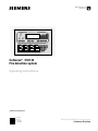
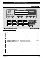
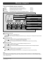
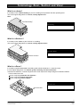
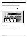
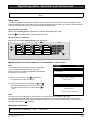
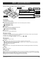
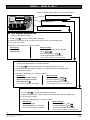
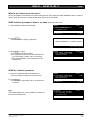
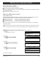
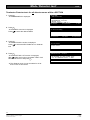
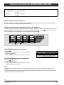
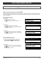
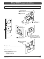
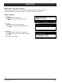
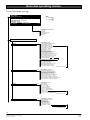
Manual CS11.2 Section 7 FIREFIGHTER FACILITY ALARM FAULT ISOL EXT BELL ISOL EXT BELL ISOLATE AlgoRex WARN SYS ISOL WARN SYS ISOLATE PREV ACK NEXT RESET ISOLATE Information Isolation Alarms Faults 7 8 9 F1 Premises manned Alarm device isolate(d) Alarm device active Alarm device fault 4 5 6 F2 Alarm delay off Remote alarm isolate(d) Remote alarm active Remote transmission fault 1 2 3 ok Detector test mode Control function isolated Mains available System fault 0 C Cerberus® CS1145 Fire detection system Operating instructions Software version EP5-Z3 Cerberus Security for People and Assets Siemens Building Technologies Cerberus Division Data and design subject to change without notice. / Supply subject to availability. E Copyright by Siemens Building Technologies AG We reserve all rights in this document and in the subject thereof. By acceptance of the document the recipient acknowledges these rights and undertakes not to publish the document nor the subject thereof in full or in part, nor to make them available to any third party without our prior express written authorization, nor to use it for any purpose other than for which it was delivered to him. CERBERUS CS1145 series Fire Indicator Panel. Model Number CI1145 Approved to AS4428.1 Siemens Building Technologies Cerberus Division CH–8708 Männedorf Switzerland 411 Ferntree Gully Road Mount Waverley 3149 Australia Tel: 03 9550 9245 Operating instructions CI1145 Introduction . . . . . . . . . . . . . . . . . . . . . . . . . . . . . . . . . . . . . . . . . . . . . . . . . . . . . 4 Operating access . . . . . . . . . . . . . . . . . . . . . . . . . . . . . . . . . . . . . . . . . . . . . . . . 5 Control console layout . . . . . . . . . . . . . . . . . . . . . . . . . . . . . . . . . . . . . . . . . . . . 6 Message categories . . . . . . . . . . . . . . . . . . . . . . . . . . . . . . . . . . . . . . . . . . . . . . 8 Terminology ’Area’, ’Section’ and ’Zone’ . . . . . . . . . . . . . . . . . . . . . . . . . . . . . 9 Normal operation . . . . . . . . . . . . . . . . . . . . . . . . . . . . . . . . . . . . . . . . . . . . . . . . 10 Mains available . . . . . . . . . . . . . . . . . . . . . . . . . . . . . . . . . . . . . . . . . . . . . . . . . . 10 Operating states ’Manned’ and ’Unmanned’ . . . . . . . . . . . . . . . . . . . . . . . . . 11 Quick reference instruction . . . . . . . . . . . . . . . . . . . . . . . . . . . . . . . . . . . . . . . . 12 Cerberus Alarm Concept . . . . . . . . . . . . . . . . . . . . . . . . . . . . . . . . . . . . . . . . . . 13 Alarm – general information . . . . . . . . . . . . . . . . . . . . . . . . . . . . . . . . . . . . . . . 14 . Alarm – what to do ? . . . . . . . . . . . . . . . . . . . . . . . . . . . . . . . . . . . . . . . . . . . . . 16 Detector zone isolation . . . . . . . . . . . . . . . . . . . . . . . . . . . . . . . . . . . . . . . . . . . 18 Detector isolation . . . . . . . . . . . . . . . . . . . . . . . . . . . . . . . . . . . . . . . . . . . . . . . . 20 Fault . . . . . . . . . . . . . . . . . . . . . . . . . . . . . . . . . . . . . . . . . . . . . . . . . . . . . . . . . . . 21 Detector test . . . . . . . . . . . . . . . . . . . . . . . . . . . . . . . . . . . . . . . . . . . . . . . . . . . . 22 Installation test . . . . . . . . . . . . . . . . . . . . . . . . . . . . . . . . . . . . . . . . . . . . . . . . . . 26 Renovation mode . . . . . . . . . . . . . . . . . . . . . . . . . . . . . . . . . . . . . . . . . . . . . . . . 27 Remote transmission isolation . . . . . . . . . . . . . . . . . . . . . . . . . . . . . . . . . . . . . 28 Alarm devices isolation . . . . . . . . . . . . . . . . . . . . . . . . . . . . . . . . . . . . . . . . . . . 29 Printer isolation . . . . . . . . . . . . . . . . . . . . . . . . . . . . . . . . . . . . . . . . . . . . . . . . . . 30 Printer paper replenishing . . . . . . . . . . . . . . . . . . . . . . . . . . . . . . . . . . . . . . . . . 31 Lamp test . . . . . . . . . . . . . . . . . . . . . . . . . . . . . . . . . . . . . . . . . . . . . . . . . . . . . . . 32 Alarm counter . . . . . . . . . . . . . . . . . . . . . . . . . . . . . . . . . . . . . . . . . . . . . . . . . . . 33 Event memory . . . . . . . . . . . . . . . . . . . . . . . . . . . . . . . . . . . . . . . . . . . . . . . . . . . 34 Set clock and date . . . . . . . . . . . . . . . . . . . . . . . . . . . . . . . . . . . . . . . . . . . . . . . 35 Overview operating menus . . . . . . . . . . . . . . . . . . . . . . . . . . . . . . . . . . . . . . . . 36 3 Siemens Building Technologies Cerberus Division e1955 11.1999 Introduction This Cerberus fire detection installation consists of the following components: System components Operating console Series of fire detectors ? Equipped Type ’CI1145’ Interactive detectors Addressable detectors Collective detectors Includes also extinguishing SECTIONS ? CO2 N2 water .......... yes Printer connected ? Location no .............................. .............................. Remote transmission connected ? yes no Cerberus Alarm Concept activated ? (operating ’manned’ / ’unmanned’ used ?) yes no Multi area installation ? yes no Duration of emergency power operation ? ......... hours This table to be filled in by the commissioning engineer. Note Make sure that all system operators of the fire detection installation are sufficiently instructed. If there is any doubt about any function or measures to be taken call the local service organization for assistance. 4 Siemens Building Technologies Cerberus Division e1955 11.1999 Operating access General: The control console is protected by a front door against unauthorized or unintentional manipulation. So no further password protection is necessary except for some special functions which are restricted to the service engineer. Possible access levels: Access level 1 Access level 3 Everybody Service access to all user functions full privileges (service engineer only) How to get USER operating access: Just open the front door. Immediate access to all user functions is possible. Ü See ’Overview operating menus’ on pages 36 up to 41 How to get SERVICE ENGINEER operating access: Log in MON 20-SEP-1999 1. Type in your service password via keypad (an entering box is displayed) and press ok password : _ 0..9,del:password Ü The confirmation «password CORRECT» or «password INCORRECT» is displayed Ü To cancel keying errors press 2. Press F2 3. Start operation 11:23:44 ok:enter c:end password CORRECT authorized access level: 2.1 C MAIN MENU FIRE section EXTINGUISHING section CONTROL in- /outputs GEOGRAPHICAL location DEVICE level logical address (CSX no.) ok:select F1:function C:end Log out Log out is not required because operating is automatically inhibited if no key is pressed within a certain time (programmable timeout 2...10 minutes). 5 Siemens Building Technologies Cerberus Division e1955 11.1999 Control console layout Firefighter facility FIREFIGHTER FACILITY 17 18 19 20 21 ALARM FAULT ISOL INFORMATION 01 manned main building EXT WARN BELL 22 SYS ISOL ISOL EXT BELL WARN SYS ISOLATE ISOLATE 23 Premises manned 9 Alarm delay off Detector 13 test mode AlgoRex R F2:menu 17c NEXT ACK RESET ISOLATE 25 26 27 28 29 Isolation 6 17a PREV Alarms 3 2 5 1 17b F1:function 24 Information 1 Total: Alarm device isolate(d) Alarm device active 11 Remote alarm active 12 Remote transmission fault 15 Mains available 16 System fault Control function 14 isolated 8 7 8 9 F1 32 7 Remote alarm 10 isolate(d) Faults 4 Alarm device fault 4 1 5 2 6 37 0 33 3 31 ok C 34 35 36 Special keys and indicators F2 30 Function key pad Special keys and indicators List Handling 1 Information indicator & key 2 Isolation indicator & key 3 Alarm indicator & key 4 Fault indicator & key Operating states 5 Premises manned indicator & key Alarm devices 6 Alarm device isolate(d) indicator & key 7 Alarm device active indicator & key 8 Alarm device fault indicator Remote Transmission 9 Alarm delay off indicator & key 10 Remote alarm isolate(d) indicator & key 11 Remote alarm active indicator 12 Remote transmission fault indicator Control and System 13 Detector test mode indicator 14 Control function isolated indicator 15 Mains available indicator 16 System fault indicator Information message list handling & indication see page 8 Isolation message list handling & indication see page 8 Alarm message list handling & indication see page 8 Fault message list handling & indication see page 8 Premises manned / unmanned switch over & indication see page 11 Isolation / de–isolation of alarm devices see page 29 Activation / deactivation of Alarm devices Indicates fault of alarm devices Immediately initiates the alarm remote transmission see page 16 Disables alarm remote transmission see page 28 Indicates active alarm remote transmission Indicates faults of the alarm remote transmission Indicates zones are in mode ’detector test’ see page 22 Indicates isolated control functions Indicates main power supply normal operation see page 10 Indicates fatal system fault 6 Siemens Building Technologies Cerberus Division e1955 11.1999 Control console layout cont. Firefighter facility 17 Text display with yellow illumination. dark, if no danger message («Alarm») is pending and no operator activity is in progress. 17a Information bar Information is context dependent 17b Message part e.g. abnormal states or menu items to be selected 17c Instruction bar Indicates the currently possible actions Common indicators 18 ALARM indicator 19 FAULT indicator 20 ISOL indicator Sound handling 21 EXT BELL ISOL indicator 22 WARN SYS ISOL indicator Indicates pending zone alarms (blinking if unacknowledged) Indicates pending zone faults (blinking if unacknowledged) Indicates pending zone isolations (blinking if unacknowledged) Indicates external bells isolated Indicates warning system isolated 23 EXT BELL ISOLATE key To isolate/de–isolate the external bells 24 WARN SYS ISOLATE key To isolate/de–isolate the warning system Message scrolling 25 PREV key To scroll messages upwards in the text display 26 NEXT key To scroll messages downwards in the text display Zone handling 27 ACK 28 RESET key 29 ISOLATE To acknowledge new messages (e.g. alarms, faults) key key To reset alarms To isolate / de–isolate zones Function key pad Message scrolling 30 Scroll up key 31 Scroll down key Corresponds to key 25 PREV on Firefighter facility Corresponds to key 26 NEXT on Firefighter facility Message & display control 32 F1 key Calls context menu (corresponding function list) 33 F2 key Calls main menu 34 ok key 35 36 C Delete key Clear key Numeric keys 0 .. 9 Numeric keys 37 see page 12 Displays intervention text or expands messages Deletes one character to the left of the cursor Cancels current input To set clock and date e.g. see page 35 7 Siemens Building Technologies Cerberus Division e1955 11.1999 Message categories There are the following message categories: Alarms danger messages acquired by the system Priority 1 Faults messages that require an immediate response Priority 2 Isolation system components out of service Priority 3 Information messages that do not require an immediate response Priority 4 FIREFIGHTER FACILITY ALARM Fire brigade REQUESTED 01 AUTOM. ALARM SMOKE main building / 1st floor room 104 FAULT ISOL EXT BELL ISOL EXT BELL ISOLATE 1 1 F1:function WARN SYS ISOL WARN SYS ISOLATE 2 ok:interv.text PREV 3 4 Zones: 1 NACK F2:menu 5 6 7 8 Zones: 1 AlgoRexR F1:function ISOLATION 01 detector main building / 1st floor RESET ISOLATE room 104 ACK NEXT FAULTS 01 detector main building / 1st floor room 104 F1:function Information Isolation Alarms Faults 7Information 8 9 F1 Premises manned Alarm device isolate(d) Alarm device active Alarm device fault 4 Alarm delay off Remote alarm isolate(d) Remote alarm active Remote transmission fault 1 Detector test mode Control function isolated Mains available System fault F2:menu Zones: 1 F2:menu Total: 1 01 detector 5 F2 main6 building / 1st floor room 104 2 3 0 C ok F1:function F2:menu Information display field Press key 2 to display the information list. Certain information messages are displayed spontaneously (e.g. warnings) if no message with a higher priority is pending. 3 Isolation display field Ü The indicator is blinking if there are unacknowledged messages in then list Press key 4 to display the list of disabled system components. This message type is displayed spontaneously if no message with a higher priority is pending. 5 Alarms display field Ü The indicator is blinking if there are unacknowledged messages in then list Press key 6 to display the list of alarms. This message type is always displayed spontaneously and overwrites all other message categories 7 Faults display field Ü The indicator is blinking if there are unacknowledged messages in then list Press key 8 to display the list of existing faults. This message type is displayed spontaneously if no message with a higher priority is pending. Note Switching from one message category to another is always possible by pressing the corresponding selection key. If a lower priority is selected, the system always goes back after a short time-out, to that message category with the highest priority. 8 Siemens Building Technologies Cerberus Division e1955 11.1999 Terminology ’Area’, ’Section’ and ’Zone’ What is an «Area»? It normally covers a whole building or part of a building and represents also the operating level. This is the logical designation for several, usually adjacent sections Area ’Main building’ AREA 01 main building 02 factory ok:section F2:menu F1:function What is a «Section»? It normally covers a floor or part of a floor in a building. This is the logical designation for several, usually adjacent zones SECTION ’fire’ 01 ground floor 02 first floor 03 second floor Section «1st floor» ok:zone F2:area F1:function What is a «Zone»? It normally comprises one room of a building (with collective detectors => several rooms) It is the logical designation of a detector group containing at least one detector Automatic fire detectors, manual call points and control outputs are always assigned to different ZONES For this reason we have zones comprising automatic fire detectors zones comprising manual call points zones comprising control outputs ZONES’fire’ 01 room 103 02 room 104 03 room 105 Zone «room 104» ok:element F2:section F1:function 9 Siemens Building Technologies Cerberus Division e1955 11.1999 Normal operation / Mains available What is «Normal operation»? The system is ready for receiving danger messages No alarm and no fault messages are pending and no part of the system is isolated Ü The system can either be in state «manned» or «unmanned» (see page 11) Ü The operating states «manned» / «unmanned» are information messages. This means that even in «normal operation» at least this message is always pending in the information list 1 FIREFIGHTER FACILITY ALARM INFORMATION 01 manned main building FAULT ISOL 1 F1:function EXT BELL ISOL WARN SYS ISOL EXT BELL ISOLATE WARN SYS ISOLATE PREV Total: 1 AlgoRex R F2:menu ACK NEXT RESET ISOLATE Information Isolation Alarms Faults 7 8 9 F1 Premises manned Alarm device isolate(d) Alarm device active Alarm device fault 4 5 6 F2 Alarm delay off Remote alarm isolate(d) Remote alarm active Remote transmission fault 1 2 3 ok Detector test mode Control function isolated Mains available System fault 0 C 2 What is «Mains available»? The green indicator 2 in the display field «Mains available» shows the state of the main power supply: It is ON as long as the main power supply is in normal operation. It is OFF if the the main power supply fails and the control unit runs on battery. 10 Siemens Building Technologies Cerberus Division e1955 11.1999 Operating states ’manned’ and ’unmanned’ Is the Cerberus Alarm Concept activated? Yes No Basic rules The operating states «Manned» and «Unmanned» are only relevant for systems in which the signals for automatic fire detectors and manual call points are processed differently, that means, the Cerberus Alarm Concept is activated. The switchover can be performed manually or automatically. Operating state «manned» Means: The operating person responsible for «Alarm» investigation is on site. Indicator 1 in the display field «Premises manned» is ON. Operating state «unmanned» Means: The responsible operating person is not on site. 1 2 Information Isolation Alarms Faults 7 8 9 F1 Premises manned Alarm device isolate(d) Alarm device active Alarm device fault 4 5 6 F2 Alarm delay off Remote alarm isolate(d) Remote alarm active Remote transmission fault 1 2 3 ok Detector test mode Control function isolated Mains available System fault 0 C 3 Manual switch over from «manned» to «unmanned» or vice versa Note For several areas, this function works only, if all areas are in the same state (unmanned or manned). With this function you switch over all areas from manned to unmanned or vice versa. 1. Switch over by pressing key 2 (toggling key) Ü Confirmation prompt is displayed 2. Confirm the switchover by pressing the ok key 3 Ü The new operating state is shown in the display Ü In the «manned mode» the state indicator 1 is ON INFORMATION 01 manned building A 02 manned building B Total: F1:function 2 F2:menu actual state: manned switch over ? ok:switch over C:cancel switched over ! actual state: unmanned Note The switchover from «manned» to «unmanned» (or vice versa) is also possible via the menu. If several organizationally autonomous systems are operated via a common multi-area terminal (areas with manned state, other areas with unmanned state) the state can only be changed via the menu, the «Premises manned» state indicator 1 is flashing. Automatic switchover From «unmanned» to «manned»: No From «manned» to «unmanned»: No Yes, time = . . . . . . . Yes, time = . . . . . . . . 11 Siemens Building Technologies Cerberus Division e1955 11.1999 Quick reference instructions How to start operating ? 1. Press F2 Ü The MAIN MENU is displayed 2. Select desired function in ’MAIN MENU’ by using and the arrow keys 3. Then press ok Ü option selected is shown inverse MAIN MENU FIRE detection EXTINGUISHING sections CONTROL in- /outputs GEOGRAPHICAL location DEVICE level logical address (CSX no.) ok:select F1:function C:end Function ’FIRE detection’ to navigate to a fire detection SECTION or ZONE or ELEMENT (= detector) in order to isolate or reactivate detector zones set detector zones on mode ’detector test’ or to terminate ’detector test’ , etc. Function ’Extinguishing section’ to navigate to an extinguishing SECTION in order to isolate detector zones related to the selected extinguishing section set detectors related to the selected extinguishing section on mode ’detector test’ or to terminate test the extinguishing ’alarm horn’ or ’warning panel’ , etc. Function ’CONTROL in-/ outputs’ to select a control SECTION or ZONE in order to isolate or reactivate a fire control function (e.g. air-conditioning shut down, etc.) initiate manually or deactivate a fire control function, etc. Function ’GEOGRAPHICAL location’ to select any SECTION or ZONE in order to isolate or reactivate a zone, etc. Function ’DEVICE level’ to initiate a specific function such as lamp test printer test, also to isolate or de–isolate the printer, etc. Function ’LOGICAL address (CSX. no.)’ to jump directly to a known logical location the complete address (AREA no./ SECTION no./ ZONE no./ELEMENT no.) must be known Notes Full list of all possible functions see ’Overview operating menus’ on pages 36 to 41 The text ’MAIN MENU’ is sometimes abbreviated to ’MENU’ because of the limited text length in the display 12 Siemens Building Technologies Cerberus Division e1955 11.1999 Cerberus Alarm Concept How does the Cerberus Alarm Concept function? When the system operates in «manned» mode, manual call points and automatic fire detectors trigger different actions in the event of an alarm. ÈÈÈÈ ÈÈÈÈ ÈÈÈÈ ÈÈÈÈ ÈÈÈÈ Alarm event manned or unmanned unmanned manned Operating mode F Local alarm ACK V1 pressed running V1 = 0 «Emergency» F pressed «Minor incident» RESET V2 pressed running V2 = 0 General alarm Remote alarm Alarm acknowledgement time «V1» This is a countdown time that is active for automatic detectors when the system operates in «manned» mode. Checks whether someone acknowledges the danger alarm message within the preprogrammed time. On expiration of this time the alarm is transmitted to the fire department. The remaining time is displayed in minutes and seconds. Alarm investigation time «V2» This is a countdown time that is active for automatic detectors when the system operates in «manned» mode. Limits the time for investigating the fire location to an individually programmed time. On expiration of this time the alarm is transmitted to the fire department. The remaining time is displayed in minutes and seconds. In case of minor incidents, an alarm must be reset before V2 expires. Normal operation V1 = ............... minutes V2 = ............... minutes 13 Siemens Building Technologies Cerberus Division e1955 11.1999 Alarm – general information How are alarm messages shown in the text display? 1st alarm message Zone «Room 104» Room 103 Corridor Room 102 Room 103 2nd alarm message Zone «Room 102» detector type Fire brigade REQUESTED 01 AUTOM. ALARM SMOKE main building / 1st floor room 104 02 AUTOM. ALARM HEAT main building / 1st floor room 102 F1:function ok:interv.text total amount of pending zone messages Zones: 2 NACK NACK 1st message + «scroll box» last message F2:menu bottom line = instruction bar Room 104 up to 2 messages can be displayed simultaneously Text Display The display consists of 3 parts: Information bar on the top line Reports the status of remote transmission. One of the following texts is indicated: Fire brigade REQUESTED FIRE BRIGADE in ... min CALL fire brigade: Tel. 000 Message part The display can show 2 messages simultaneously: Upper section shows 1st message Lower section shows last message Instruction bar Indicates the currently possible actions. Message scrolling If more than 2 messages have been reported, scrolling becomes necessary in order to show all reported messages in the ’upper section’ (one after the other). and . Scrolling is done by PREV and NEXT or with the arrow keys Message text The message consists of 3 lines: First line: A message number (which does not necessarily correspond to the alarm order) The kind of detection device: automatic detector (SMOKE, HEAT, FLAME) or manual call point (MCP). Isolated alarms have the additional text ’ISOL’ The Message state (see below) Second line: Customer text line 1 with programmable additional location information (logical address of the alarming zone) Third line: Customer text line 2 Message state Most messages have to be acknowledged. If they occur, they are in the state ’not acknowledged’. By pressing ACK they change to the ’acknowledged’ state. The state is indicated by the texts ’NACK’ for ’not acknowledged’ and ’ACKD’ for ’acknowledged’ at the end of the first line of the message. Messages which do not have to be acknowledged do not have these texts. 14 Siemens Building Technologies Cerberus Division e1955 11.1999 Alarm – general information cont. Message order Messages are presented in the following order: 1. unacknowledged alarms 2. acknowledged alarms 3. isolated alarms Within these categories the messages are sorted chronologically. Acknowledge Ü Each message has to be acknowledged separately 1. Select the desired unacknowledged message 2. Press Ü The message state text changes from ’NACK’ to ’ACKD’ Ü The unacknowledged message is placed on top ACK Supplementary information The logical address of the alarming zone (if programmed) Fire brigade REQUESTED Zones: 2 01 AUTOM. ALARM SMOKE NACK main building / 1st floor 01/001/004 room 104 02 AUTOM. ALARM HEAT NACK main building / 1st floor 01/001/006 room 102 F1:function ok:interv.text F2:menu message state Fire brigade REQUESTED Zones: 2 01 AUTOM. ALARM HEAT NACK main building / 1st floor 01/001/006 room 104 02 AUTOM. ALARM SMOKE ACKD main building / 1st floor 01/001/004 room 102 F1:function ok:interv.text F2:menu logical address of the alarming zone NACK = not acknowledged message state ACKD = acknowledged How can an intervention text be read out ? 1. Press «Alarms» key and select the desired message by pressing NEXT or PREV , if necessary (the selected message is displayed in inverted colors) 2. Press ok Ü The intervention text is displayed (if programmed) Fire brigade REQUESTED Zones: 2 01 AUTOM. ALARM SMOKE ACKD main building / 1st floor 01/001/004 room 104 02 AUTOM. ALARM HEAT ACKD main building / 1st floor 01/001/006 room 102 F1:function ok:interv.text F2:menu Fire brigade REQUESTED Zones: DANGER: hazardeous materials !! -> alert emergency squad 2 intervention text 3. Pressing ok again returns back to the original message ok:message Reset Ü Each message has to be reset separately Ü Unacknowledged messages are reset in the same way as acknowledged ones 1. Select the message to be reset Fire brigade REQUESTED Zones: 2 01 AUTOM. ALARM SMOKE ACKD main building / 1st floor 01/001/004 room 104 02 AUTOM. ALARM HEAT ACKD main building / 1st floor 01/001/006 room 102 F1:function ok:interv.text F2:menu 2. Press RESET Ü The confirmation dialog is displayed 3. Press ACK to confirm PRESS ACKNOWLEDGE TO CONFIRM RESET any other key:end 15 Siemens Building Technologies Cerberus Division e1955 11.1999 Alarm – what to do ? Top line of display reports status of remote transmission: ’CALL fire brigade: TEL. 000’ ............ FIREFIGHTER FACILITY AlgoRex 1 ’FIRE BRIGADE in .... ’ ............ 3 Fire brigade REQUESTED ............ 2 " 'Fire brigade REQUESTED' Alarm is already transmitted 1. Press ACK for each pending alarm message 1 2. Read the fire location of the 1st alarm in the upper half of the text display field 3. Go to the fire location 4. Decide on «Emergency» or «Minor incident»: Emergency: Minor incident: Save people Fight the fire Immediately try to stop the fire brigade Press RESET 3 and acknowledge by ACK 1 for each pending alarm message The system reverts to normal operation " 'FIRE BRIGADE in 4:31 (min)' Alarm will be transmitted in the time indicated 1. Press ACK 1 for each pending alarm message (before time is 0:00) 2. Read the fire location of the 1st alarm in the upper half of the text display field 3. Go to the fire location 4. Decide on «Emergency» or «Minor incident»: Emergency: Minor incident: Immediately actuate nearest manual call point or the key ’Alarm delay off’ 2 Immediately press RESET 3 and acknowledge by ACK 1 for each pending alarm message The alarm message is transmitted The system reverts to normal operation " 'CALL fire brigade: TEL. 000' 1. Press 1 for each pending alarm message 2. Read the fire location of the 1st alarm in the upper half of the text display field ACK 3. Go to the fire location 4. Decide on «Emergency» or «Minor incident»: Emergency: Minor incident: Immediately call the fire brigade (e.g. TEL. 000) Immediately press RESET 3 and acknowledge by ACK 1 for each pending alarm message the alarm message is transmitted The system reverts to normal operation 16 Siemens Building Technologies Cerberus Division e1955 11.1999 Alarm – what to do ? cont. What to do if alarm cannot be reset ? As long as a detector still detects a fire phenomena (smoke, heat, flame) the alarm cannot be reset. In order to remove such an alarm the corresponding detector zone has to be isolated. ZONE isolation procedure if zone is on alarm (Example ZONE ’fire’) 1. Select ZONE on alarm to be isolated ALARMS 01 AUTOM. ALARM SMOKE main building/1st floor conference room F1:function Zones: 1 ACKD F2:menu 2. Press ISOLATE Ü The confirmation dialog is displayed PRESS ACKNOWLEDGE TO CONFIRM ISOLATE any other key:end 3. Press ACK to confirm Ü The selected ZONE is isolated Ü It is displayed spontaneously in the Alarms list (if no messages of higher order are pending) Ü The isolated ZONE is as well displayed in the Isolation list ALARMS 01 ISOL AUTOM. ALARM SMOKE main building/1st floor conference room F1:function Zones: 1 ACKD F2:menu ZONE de–isolation procedure 1. Select the isolated ZONE in the alarms list Ü The message is displayed in inverted colors 2. Press ISOLATE Ü The ZONE is reactivated, that is, the isolation is cancelled Note The isolated ZONE may for de–isolation as well be selected in the Isolation list ALARMS 01 ISOL AUTOM. ALARM SMOKE main building/1st floor conference room F1:function ISOLATION 01 detector zone ISOLATED main building/1st floor conference room F1:function Zones: 1 ACKD F2:menu Zones: 1 F2:menu 17 Siemens Building Technologies Cerberus Division e1955 11.1999 Detector zone, temporary isolation What is ISOLATION of a ZONE ? Isolated zones have the following characteristics: The zone state (alarm and fault) is evaluated and displayed Alarms on isolated zones do NOT activate any control outputs (e.g. warning system, external bell, extinguishing, remote transmission) Isolated alarms are identified by the text ’ISOL’ When does a ZONE have to be isolated ? If zones are NOT in alarm ZONES equipped with automatic fire detectors or manual call points can be temporarily isolated. This is only necessary in exceptional situations, for example while major construction is in progress: ZONE with smoke detectors if smoke or dust is produced by unusual work ZONE with heat detectors if heat or steam is produced by unusual work ZONE with manual call point if there is a possibility of inadvertent actuation As soon as conditions have returned to normal, ISOLATED ZONES must immediately be de–isolated again. If zones are in alarm If zones in alarm cannot be reset because they still detect an alarm condition (e.g. smoke) then they can be isolated. As soon as conditions have returned to normal, ISOLATED ZONES must be immediately switched on again. ZONE isolation procedure if zone is NOT on alarm (Example ZONE ’fire’) 1. Press F2 Ü The MAIN MENU is displayed 2. Press ok Ü The AREAS overview is displayed Press to select the desired AREA 3. Press ok Ü The SECTIONS overview is displayed Press to select the desired SECTION 4. Press ok Ü The ZONES overview is displayed Press to select the desired ZONE MAIN MENU FIRE detection EXTINGUISHING sections CONTROL in- /outputs GEOGRAPHICAL location DEVICE level logical address (CSX no.) ok:select F1:function C:end AREAS 01 main building 02 factory ok:section F2:menu F1:function F2:area F1:function SECTIONS ’fire’ 01 ground floor 02 1st floor ok:zone ZONES ’fire’ 01 room 101 02 room 102 03 storage room 04 conference room 05 corridor ok:element F2:section F1:function Ü continued on next page 18 Siemens Building Technologies Cerberus Division e1955 11.1999 Detector zone, temporary isolation 5. Press F1 Ü The FUNCTION LIST ’zone’ is displayed Select the function ’ISOLATE zone’ Press ok to confirm Ü The selected ZONE is isolated Ü It is displayed spontaneously (if no messages of higher priority are pending). FUNCTION LIST ’zone’: ISOLATE zone DE–ISOLATE zone set zone -> TEST set zone -> TEST OFF activate ZONE TEST set zone -> RENOVATION ok:execute F1:zones ISOLATION 01 detector zone ISOLATED main building/1st floor conference room F1:function cont. C:end Zones: 1 F2:menu ZONE reactivation procedure 1. Select the message category by pressing the Isolation key 2. Select the zone to be de–isolated Ü The message is displayed in inverted colors ISOLATION 01 detector zone ISOLATED main building/1st floor conference room F1:function Zones: 1 F2:menu 3. Press ISOLATE Ü The ZONE is reactivated, that is, the isolation is cancelled 19 Siemens Building Technologies Cerberus Division e1955 11.1999 Isolation of individual detectors When does a detector have to be isolated ? Only when it is damaged or defective until it is replaced. Note An isolated detector cannot generate any messages. The isolation of detectors only makes sense if the corresponding ZONE is de–isolated Isolate a detector via the menu Steps 1 to 4 are identical to «Zone isolation» as described above 5. Press ok Ü The ELEMENTS summary is displayed Press to select the desired ELEMENT 6. Press F1 Ü The FUNCTION LIST ’element’ is displayed Press to select the function «ISOLATE element» and press ok Ü The selected detector is isolated and displayed spontaneously if no messages of higher priority are pending. ELEMENTS ’fire’ 01 conference room 02 conference room 03 conference room 04 conference room F2:zone F1:function FUNCTION LIST ’element’: poll INFORMATION ’element’ ISOLATE element DE–ISOLATE element ACTIVATE element DEACTIVATE element ok:execute F1:element C:end Note If all elements of a zone are isolated, the corresponding zone is automatically isolated as well. ISOLATION 01 detector ISOLATED main building / 1st floor conference room F1:function Reactivate a detector (element) 1 F2:menu 1. Select the message category by pressing the Isolation key. The message is displayed in inverted colors. ISOLATION 01 detector ISOLATED main building / 1st floor conference room 01 detector ISOLATED main building / 1st floor 2. Press F1 Ü The FUNCTION LIST ’element’ is displayed Press to select the function «DE–ISOLATE element» and press ok Ü The detector is reactivated FUNCTION LIST ’element’ poll INFORMATION ’element’ ISOLATE element DE–ISOLATE element ACTIVATE element DEACTIVATE element F1:function ok:execute Zones: Zones: 1 F2:menu F1:element C:end Isolate a detector when a fault message is pending 1. Select the message category by pressing the Faults key, then select the desired message by scrolling with , if necessary. The selected message is displayed in inverted colors. 2. Press F1 Ü The FUNCTION LIST ’element’ is displayed Press to select the function «ISOLATE element» and press ok to confirm Ü The detector is reactivated 20 Siemens Building Technologies Cerberus Division FAULTS 01 detector main building / 1st floor room 102 F1:function F2:menu FUNCTION LIST ’element’ poll INFORMATION ’element’ ISOLATE element DE–ISOLATE element ACTIVATE element DEACTIVATE element ok:execute F1:element C:end e1955 11.1999 Fault What to do in case of reported fault messages? 1. Confirm the message by pressing ACK 2. Read the fault location on the display 3. Go to the fault location 4. If the fault cannot be removed call the Cerberus service organization What remedies are available to the user? Defective automatic detector Go to the location of the defective detector, if the detector is missing: Ü reinsert the detector if the detector is defective: Ü replace it with a spare detector Important: only replace a defective detector with a unit of the same type. Defective manual call point Go the location of the defective call point, if the glass pane is broken: Ü replace the glass pane if there is any other defect: Ü call the Cerberus service organization Printer out of paper Go to the printer, Ü insert a new paper roll, see section «Printer: Paper replenishing» page 31 Mains supply failure Mains failure in the public supply network: Ü no action required the emergency power battery supplies the system for at least 24.5 hours (depending on the user’s specification up to 72 hours) Mains supply ok: Ü check the power fuse (main distribution panel of the building) and replace the fuse, if it is blown. FAULTS 01 detector main building / 1st floor room 102 F1:function FAULTS 01 call point GLASS BROKEN main building / 2nd floor CORRIDOR F1:function FAULTS 01 printer terminal PAPER END main building / 1st floor conference room F1:function FAULTS 01 mains failure control unit, basement F1:function Zones: 1 F2:menu Zones: 1 F2:menu Zones: 0 F2:menu Zones: 0 F2:menu Note Isolated detectors also cause a fault message. ÁÁÁÁÁÁÁÁÁÁÁÁÁÁÁÁÁÁÁÁÁÁÁÁÁÁÁÁÁÁÁÁÁ ÁÁÁÁÁÁÁÁÁÁÁÁÁÁÁÁÁÁÁÁÁÁÁÁÁÁÁÁÁÁÁÁÁ For all other faults call the Cerberus service organization 21 Siemens Building Technologies Cerberus Division e1955 11.1999 Mode ’Detector test’ What is the «Detector test» mode for? The mode «Detector test» allows individual on-site function testing of automatic fire detectors and manual call points without generating an alarm message. Automatic fire detectors are actuated with a special detector tester. Interactive detectors are set to the special parameter set ’Test’ in order to achieve a fast activation with the detector tester. Manual call points are activated depending on the type: – From externally with a special test key without breaking the glass pane or opening the housing. – Simply by opening the door of the manual call point. Test alarm is the active state of automatic fire detectors or manual call points in «Detector test» mode. A test alarm does not generate a danger message in the control console. That means that neither acoustical alarm devices nor remote transmission or any other control functions are activated. Test alarms are recorded in the event memory and logged spontaneously, if a printer is connected. How to set detectors or manual call points to mode «Detector test»? This is normally done on the section level, but also possible on the zone level. It is not possible to set an individual fire detector or manual call point (element) to «Detector test». Zones or sections set to «Detector test» are displayed spontaneously as a message in the category ’Isolation’ Set all detector zones within a SECTION to «Detector test» 1. Press F2 Ü The MAIN MENU is displayed to select the desired menu item. Press 2. Press ok Ü The AREAS overview is displayed Press to select the desired AREA MAIN MENU FIRE detection EXTINGUISHING sections CONTROL in- /outputs GEOGRAPHICAL location DEVICE level logical address (CSX no.) ok:select F1:function AREAS 01 main building 02 factory ok:section 3. Press ok Ü The SECTIONS overview is displayed Press to select the desired SECTION F2:menu F1:function SECTIONS 01 ground floor 02 1st floor 03 lift shaft 04 2nd floor ok:zone 4. Press F1 Ü The FUNCTION LIST ’section’ is displayed With select the function «set all DETECTOR zones –> TEST» and press ok (automatic detectors only). C:end F2:area F1:function FUNCTION LIST ’section’: ISOLATE all DETECTOR zones DE–ISOLATE all DETECTOR zones ISOLATE all CALL POINT zones DE–ISOLATE all CALL POINT zones set all DETECTOR zones -> TEST terminate TEST of all DETECTOR zones ok:execute F1:sections C:end Ü All zones of automatic detectors that belong to this section are set to «Detector test» Indicator «Detector test mode» is on Same procedure for manual call points 22 Siemens Building Technologies Cerberus Division e1955 11.1999 Mode ’Detector test’ cont. Recommendations for detector test Perform the function test periodically. The interval of this test is determined by the service engineer. Switch only the fire detectors of one SECTION at a time to «Detector test», never the entire building. For manual call points the function test needs to be performed only based on a spot-check. Test automatic fire detectors and manual call points of the same room always separately. Do not set them to «Detector test» simultaneously. After the test work has been completed immediately cancel the mode «Detector test». Testing of automatic AlgoRex detectors Neural smoke detector 1. Set the SECTION (or zone) to «Detector test» mode. 2. Place the detector tester on the detector. Observe the marking! Ü For smoke detectors and multisensor smoke detectors the detector exchanger and tester DZ1193 is needed: Ü For heat detectors the detector tester RE6T is required: The temperature rise is simulated with a hot-air blower Heat detector Smoke detector 3. Wait until the response indicator on the detector flashes. 4. Remove the detector tester. Ü The function test is completed. Go to next detector Detector exchanger and tester DZ1193 Detector tester RE6T Note Smoke detectors, multisensor smoke detectors and heat detectors have different housings (see illustration). Testing of manual call points Manual call points DM1101, DM1151 (type KAC) 1. Set the manual call point ZONE to «Detector test» mode. 2. Insert the test key into the opening «Test alarm» is simulated. 3. Wait until the response indicator of the manual call point flashes. Test key 4. Remove the test key. Ü The function test is completed 23 Siemens Building Technologies Cerberus Division e1955 11.1999 Mode ’Detector test’ cont. Terminate «Detector test» for all detector zones within a SECTION 1. Press F2 Ü The MAIN MENU is displayed 2. Press ok Ü The AREAS overview is displayed to select the desired AREA Press MAIN MENU FIRE detection EXTINGUISHING sections CONTROL in- /outputs GEOGRAPHICAL location DEVICE level logical address (CSX no.) ok:select F1:function AREAS 01 main building ok:section 3. Press ok Ü The SECTIONS overview is displayed Press to select the SECTION that is on ’detector test’ F2:menu F1:function SECTIONS 01 ground floor 02 1st floor 03 lift shaft 04 2nd floor ok:zone 4. Press F1 Ü The FUNCTION LIST ’section’ is displayed With select the function «terminate TEST of all DETECTOR zones» and press ok C:end F2:area F1:function FUNCTION LIST ’section’ : DE–ISOLATE all DETECTOR zones ISOLATE all CALL POINT zones DE–ISOLATE all CALL POINT zones set all DETECTOR zones -> TEST terminate TEST of all DETECTOR zones set all CALL POINT zones -> TEST ok:execute F1:sections C:end Ü The «Detector test» is now cancelled for all detector zones of this section 24 Siemens Building Technologies Cerberus Division e1955 11.1999 Mode ’Detector test’ cont. Poll ’test alarms’ in the event memory 1. Press F2 Ü The MAIN MENU is displayed to select DEVICE level Press 2. Press ok Ü The STATIONS overview is displayed Press to select the desired STATION MAIN MENU FIRE detection EXTINGUISHING sections CONTROL in- /outputs GEOGRAPHICAL location DEVICE level logical address (CSX no.) ok:select F1:function STATIONS 01 CC1142 CBUS no1 02 CI1142 CBUS no2 05 CT1142 CBUS no5 ok:funct.unit 3. Press F1 Ü The function list Control unit is displayed to select ’poll EVENT MEMORY’ Press C:end F2:menu F1:function FUNCTION LIST ’terminal’: poll INFORMATION ’terminal’ initiate LAMP TEST set contrast of DISPLAY set sound level of BUZZER poll EVENT MEMORY ’terminal’ ISOLATE PRINTER ’terminal’ ok:execute F2:stations c:end 4. Press ok Ü The function list Event Memory is displayed Press to select ’poll all TEST ALARM’ messages FUNCTION LIST ’event memory’: poll all messages poll all DANGER messages poll all FAULT messages poll all DISCONNECTION messages poll all INFORMATION messages poll all TEST-ALARM messages ok:execute F1:station F2:->date/time 5. Press ok Ü The TEST Alarms are displayed use and to poll the test alarms EVENT MEMORY **** TOP OF LIST **** 03-SEPT-1997 16:15:52 INFORMATION +detector TEST ACTIVATION main building / 1st floor room 102 04-SEPT-1997 09:00:59 INFORMATION ^/v:scroll F1:print F2:->date/time 25 Siemens Building Technologies Cerberus Division e1955 11.1999 Mode ’Installation test’ What is the mode «Installation test» for? The mode «Installation test» allows to test the correct function of the whole fire detection system including fire controls, acoustical alarm devices, etc. All functions remain enabled. Make sure that the remote transmission is isolated or the fire department is informed about the test activities. In the mode ’Installation test’ interactive detectors become more sensitive and respond faster (response behavior as in mode «Detector test»). The mode ’Installation test’ shall be carried out only by security staff and serves basically to test the alarm organization and fire controls. After the test work has been completed immediately cancel the mode «Installation test». Mode «Installation test» is normaly enabled and disabled on the level ’ZONE’ but also possible on the level ’SECTION’ Setting a zone to mode «Installation test» MAIN MENU FIRE detection EXTINGUISHING sections CONTROL in- /outputs GEOGRAPHICAL location DEVICE level logical address (CSX no.) ok:select F1:function 1. Press F2 Ü The MAIN MENU is displayed 2. Press ok Ü The AREAS overview is displayed Press to select the desired AREA AREAS 01 main building ok:section 3. Press ok Ü The SECTIONS overview is displayed Press to select the desired SECTION F2:menu F1:function SECTIONS ’fire’ 01 ground floor 02 1st floor 03 lift shaft 04 2nd floor ok:zone 4. Press ok Ü The ZONES overview is displayed Press to select the desired ZONE F2:area F1:function ZONES ’fire’ 01 room 101 02 1st floor 03 storage room 04 conference room 05 corridor ok:element 5. Press F1 Ü The FUNCTION LIST ’zone’ is displayed With scroll to the function «set zone –> INSTALLATION TEST» and press Ü The ZONE is set to mode «Installation test» C:end ok F2:section F1:function FUNCTION LIST ’zone’ : set zone -> TEST OFF activate FAULT TEST set zone -> RENOVATION set zone -> RENOVATION OFF set zone -> INSTALLATION TEST set zone -> INSTALLATION TEST OFF ok:execute F1:zones C:end Termination of mode «Installation test» of a zone 1. Press the Information key and select the desired message by pressing , if necessary. The selected message is displayed in inverted colors. INFORMATION Total: 01 detector zone INSTALL. TEST main building / 1st floor conference room F1:function 2. Press F1 The FUNCTION LIST ’zone’ is displayed With scroll to the function «set zone –> INSTALLATION TEST OFF» and press ok Ü The ZONE is set to normal operation mode 1 F2:menu FUNCTION LIST ’zone’: set zone -> TEST OFF activate FAULT TEST set zone -> RENOVATION set zone -> RENOVATION OFF set zone -> INSTALLATION TEST set zone -> INSTALLATION TEST OFF ok:execute F1:zones C:end 26 Siemens Building Technologies Cerberus Division e1955 11.1999 Mode ’Renovation’ What is the «Renovation» mode for? In «Renovation» mode, automatic detectors are much less sensitive. This may be required while unusual work is in progress (e.g. during renovation of a building). The fire detection system remains working, the remote transmission of alarm and fault messages is enabled. Manual call points work as in normal operation mode. Detectors in the mode ’Renovation’ are from the insurance and approval point of view out of order. This is why the ’isolation’ message is generated. Mode ’Renovation’ is enabled and disabled on the level ’ZONE’ only. Mode ’Renovation’ is enabled and disabled on the level ’ZONE’ only. Setting a zone to mode «Renovation» 1. Press F2 Ü The MAIN MENU is displayed 2. Press Ü The AREAS overview is displayed Press to select the desired AREA ok MAIN MENU FIRE detection EXTINGUISHING sections CONTROL in- /outputs GEOGRAPHICAL location DEVICE level logical address (CSX no.) ok:select F1:function AREAS 01 main building ok:section 3. Press ok Ü The SECTIONS overview is displayed Press to select the desired SECTION F1:function F2:area F1:function ZONES ’fire’ 01 room 101 02 1st floor 03 storage room 04 conference room 05 corridor ok:element 5. Press F1 Ü The FUNCTION LIST ’zone’ is displayed With scroll to the function «set zone –> RENOVATION» and press ok Ü The ZONE is set to mode «Renovation» F2:menu SECTIONS ’fire’ 01 ground floor 02 1st floor 03 lift shaft 04 2nd floor ok:zone 4. Press ok Ü The ZONES overview is displayed Press to select the desired ZONE C:end F2:section F1:function FUNCTION LIST ’zone’: DE–ISOLATE zone set zone –> TEST set zone -> TEST OFF activate FAULT TEST set zone -> RENOVATION set zone -> RENOVATION OFF ok:execute F1:zones C:end Termination of mode «Renovation» of a zone 1. Press the Isolation key and select the desired message by pressing , if necessary. The selected message is displayed in inverted colors. ISOLATION 01 detector zone RENOVATION main building / 1st floor conference room F1:function 2. Press F1 The FUNCTION LIST ’zone’ is displayed With scroll to the function «set zone –> RENOVATION OFF» and press ok Ü The ZONE is set to normal operation mode FUNCTION LIST ’zone’: set zone -> TEST set zone -> TEST OFF activate FAULT TEST set zone -> RENOVATION set zone -> RENOVATION OFF set zone -> INSTALLATION TEST ok:execute F1:zones Zones: 1 F2:menu C:end 27 Siemens Building Technologies Cerberus Division e1955 11.1999 Remote transmission ISOLATE/DE–ISOLATE This system is equipped with a remote transmission facility for FIRE ALARM Yes, destination: No for FAULT Yes, destination: No ............................................................................................... ............................................................................................... What is «Remote transmission»? Remote transmission establishes a transmission path to the fire department in the event of a FIRE ALARM. For FAULT there is normally a separate path established. When does the remote transmission have to be isolated? Normally the remote transmission operates in active stand-by. Isolation is needed only in special cases, for example for testing the control functions. For this test the Remote alarm isolate key 1 on the control console has to be pressed. The «ISOLATED» state is signalled by the indicator 2 . Information Isolation Alarms Faults 7 8 9 F1 Premises manned Alarm device isolate(d) Alarm device active Alarm device fault 4 5 6 F2 Alarm delay off Remote alarm isolate(d) Remote alarm active Remote transmission fault 1 2 3 ok Detector test mode Control function isolated Mains available System fault 0 C 2 1 ISOLATING the remote transmission Press key 1 Ü The corresponding isolation message is displayed Ü Indicator 2 turns on Ü The FIRE ALARM remote transmission is isolated ISOLATION Zones: 0 01 RT ’fire’ ISOLATED main building remote transmission channel FIRE 02 RT ’fire’ ISOLATED factory remote transmission channel FIRE F1:function F2:menu DE–ISOLATING the remote transmission Press key 1 (toggling key) Ü Indicator 2 turns off Ü The FIRE ALARM remote transmission is de–isolated and switched to stand-by Note The remote transmission can also be isolated and de–isolated via the menu, separately for «Alarm» and «Fault». The remote transmission must be periodically checked by activating a manual call point. The fire department must be notified before the test is initiated. 28 Siemens Building Technologies Cerberus Division e1955 11.1999 Alarm devices ISOLATE/DE–ISOLATE When do alarm devices (horns, sirens, etc.) have to be isolated ? Normally the alarm devices operate in active stand-by. Isolation is needed only in special cases, for example for testing the control functions. Information Isolation Alarms Faults 7 8 9 F1 Premises manned Alarm device isolate(d) Alarm device active Alarm device fault 4 5 6 F2 Alarm delay off Remote alarm isolate(d) Remote alarm active Remote transmission fault 1 2 3 ok Detector test mode Control function isolated Mains available System fault 0 C 2 1 ISOLATING the alarm devices Press key 1 Ü The corresponding isolation message is displayed Ü Indicator 2 turns on Ü The alarm devices (warning system AND external bell) are isolated ISOLATION 01 external bell ISOLATED main building external horn (horn II) 02 warning system ISOLATED main building internal horn (horn I) F1:function Zones: 0 F2:menu DE–ISOLATING the alarm devices Press key 1 (toggling key) Ü Indicator 2 turns on Ü The alarm devices are de–isolated and switched to stand-by Note The alarm devices can also be isolated and de–isolated via the menu. 29 Siemens Building Technologies Cerberus Division e1955 11.1999 Printer ISOLATE/DE–ISOLATE This system is equipped with a printer Yes No When does the printer have to be ISOLATED? Normally the printer (if installed) operates in active stand-by. Isolation is needed only in special cases (for example to change the paper). The printer can be isolated and de–isolated via the menu. The «ISOLATED» state is shown on the display. ISOLATING the printer 1. Press F2 Ü The MAIN MENU is displayed With choose the function «DEVICE level» 2. Press ok Ü The STATIONS overview is displayed Press , if necessary, to select the desired station (control unit or terminal) MAIN MENU FIRE detection EXTINGUISHING sections CONTROL in- /outputs GEOGRAPHICAL location DEVICE level logical address (CSX no.) ok:select F1:function STATIONS 01 control unit CC1140 ground floor 02 terminal CT11 corridor 1st floor ok:funct.unit 3. Press F1 Ü The FUNCTION LIST ’control unit’ is displayed to select «ISOLATE printer» and press ok Press Ü The printer is isolated DE–ISOLATING the printer 1. Press the Isolation key and select the desired message by pressing , if necessary. The selected message is displayed in inverted colors. C:end F2:menu F1:function FUNCTION LIST ’terminal’: initiate LAMP TEST set contrast of DISPLAY set sound level of BUZZER poll EVENT MEMORY ’terminal’ ISOLATE printer ’terminal’ DE–ISOLATE printer ’terminal’ ok:execute F1:stations ISOLATION Zones: 01 printer ’terminal’ ISOLATED reception ground floor F1:function 2. Press F1 Ü The FUNCTION LIST ’control unit’ is displayed With select the function «DE–ISOLATE printer» and press ok Ü The printer is de–isolated C:end FUNCTION LIST ’terminal’: set contrast of DISPLAY set sound level of BUZZER poll EVENT MEMORY ’terminal’ ISOLATE printer ’terminal’ DE–ISOLATE printer ’terminal’ initiate PRINTER TEST ’terminal’ ok:execute F1:stations 0 F2:menu C:end 30 Siemens Building Technologies Cerberus Division e1955 11.1999 Printer B2Q191: paper replenishing Valid for this system Yes, system equipped with printer B2Q191 No printer of this type installed 1 Isolate the printer first Swing out printer unit 2 Remove the used paper roll ÎÎÎÎ ÎÎÎ ÎÎÎÎ ÎÎÎ ÎÎÎ ÎÎÎÎ ÎÎÎ ÎÎÎ ÎÎÎ 3 5 Lift the paper flap and slide a new paper roll over the spindle The paper can be transported by means of the knurled wheel A 4 7 Press the winding up key De–isolate the printer 6 Press the leading edge of the paper lightly against the flap and feed it into the printer through the slot. Push down the release lever A to insert the paper. Thread the leading edge of the paper around the take-up roller and fix it with the clamp Print intensity If the print intensity is too low, call the Cerberus service organization. Spare paper rolls Cerberus part no. 379 977 (= 4 pcs.) or – JUJU TP 50KS-A – HONSHU PS 65 B1 – MITSUBISHI F-200 U7X 31 Siemens Building Technologies Cerberus Division e1955 11.1999 Lamp test What is the «Lamp test» used for? For testing the correct functioning of all indicators (LEDs), the display, and the alarm buzzer. All visual and audible devices of the control console are activated for a few seconds. Initiate lamp test 1. Press F2 Ü The MAIN MENU is displayed With choose the function «DEVICE level» 2. Press ok Ü The STATIONS overview is displayed Press to select the desired station (terminal) MAIN MENU FIRE detection EXTINGUISHING sections CONTROL in- /outputs GEOGRAPHICAL location DEVICE level logical address (CSX no.) ok:select F1:function STATIONS 01 control unit CC1140 ground floor 02 terminal CT11 corridor 1st floor ok:funct.unit 3. Press F1 Ü The FUNCTION LIST ’terminal’ is displayed Press to select «initiate LAMP TEST» and press ok Ü The lamp test is initiated C:end F2:menu FUNCTION LIST ’terminal’: poll INFORMATION ’terminal’ initiate LAMP TEST set contrast of DISPLAY set sound level of BUZZER poll EVENT MEMORY (terminal) ISOLATE PRINTER (terminal) ok:execute F1:stations F1:function C:end 32 Siemens Building Technologies Cerberus Division e1955 11.1999 Alarm counter What is the purpose of polling the alarm counter? The alarm counter shows the number of past alarm events. Polling alarm counter 1. Press F2 Ü The MAIN MENU is displayed 2. Press ok Ü The AREAS overview is displayed Press to select the desired AREA MAIN MENU FIRE detection EXTINGUISHING sections CONTROL in- /outputs GEOGRAPHICAL location DEVICE level logical address (CSX no.) ok:select F1:function AREAS 01 main building ok:section 3. Press F1 Ü The FUNCTION LIST ’area’ is displayed Press to select «poll COUNTER ’fire alarms’» or «poll COUNTER ’remote alarms’» and press ok C:end F2:menu F1:function FUNCTION LIST ’area’: switching MANNED/UNMANNED poll COUNTER ’fire alarms’ poll COUNTER ’remote alarms’ DE–ISOLATE alarm HORNS ISOLATE alarm HORNS alarm HORNS –> START ok:execute F1:areas C:end Ü The number of alarms is displayed COUNTER ’fire alarms’ : 4 33 Siemens Building Technologies Cerberus Division e1955 11.1999 Event memory Polling event memory of an ’AREA’ 1. Press F2 Ü The MAIN MENU is displayed MAIN MENU FIRE detection EXTINGUISHING sections CONTROL in- /outputs GEOGRAPHICAL location DEVICE level logical address (CSX no.) ok:select F1:function 2. Press Ü The AREAS overview is displayed to select the desired AREA Press ok C:end AREAS 01 main building 02 machine building 03 warehouse building ok:section 3. Press F1 Ü The FUNCTION LIST ’area’ is displayed Press to select «poll EVENT MEMORY» F2:menu F1:function FUNCTION LIST ’area’: ISOLATE REMOTE transm. ’fire’ DE–ISOLATE REMOTE transm. ’others’ ISOLATE REMOTE transm. ’others’ DE–ISOLATE REMOTE transm. ’fault’ ISOLATE REMOTE transm. ’fault’ poll EVENT MEMORY ok:execute F1:areas C:end 4. Press ok Ü The FUNCTION LIST ’event memory’ is displayed Press , if necessary, to select the desired function and press ok Ü The display now shows the desired list. Either the latest entry is visible completely, older entries (if existing) can be scrolled by pressing Note with F2 :–>date/time a entry of a particular date/time can be selected and displayed. FUNCTION LIST ’event memory’: poll all messages poll all DANGER messages poll all FAULT messages poll all DISCONNECTION messages poll all INFORMATION messages poll all TEST-ALARM messages ok:execute F1:areas F2:->date/time EVENT MEMORY machine building engine room 21-FEB-1996 11:26:43 INFORMATION -detector zone INSTALL. TEST machine building compressor room ^/v:scroll F1:print F2:->date/time Printing selected entries of the event memory Steps 1..4 are identical to «Polling event memory of an area» as described above 5. Press F1 Ü The ’printout EVENT MEMORY’ menu is displayed Press F2 to print all entries or select desired range of date and time to print out particular events. and to set date and time and press Use select the next field. Press ok to print out selected entries. F1 printout EVENT MEMORY VV Printout starts at: 08:00 21-FEB-1996 Printout stops at: to Ü During the print out procedure on the bottom line a flashing”printing” in inverted coulors is displayed. ok:set 08:00 21-FEB-1996 F1:next field F2:print all printout EVENT MEMORY ... printing ... Note The event memory can only be printed out, if the printer is connected to the operated terminal. 34 Siemens Building Technologies Cerberus Division e1955 11.1999 Set clock and date Normally the date and time do not have to be corrected! The date and time are set by the service engineer when installing the system. The summer/winter time changeover is performed automatically. Time and date are always displayed when the password is entered. Setting the clock 1. Press F2 Ü The MAIN MENU is displayed 2. Press F1 Ü The FUNCTION LIST ’installation’ is displayed MAIN MENU FIRE detection EXTINGUISHING sections CONTROL in- /outputs GEOGRAPHICAL location DEVICE level logical address (CSX no.) ok:select F1:function FUNCTION LIST ’installation’: set CLOCK set DATE re-configuration C-bus ok:execute 3. Press ok Ü An input prompt is displayed Enter the current time and press ok (2 digits each for hours / minutes / seconds) Ü The new time is read in and loaded 1. Press F2 Ü The MAIN MENU is displayed 2. Press F1 Ü The FUNCTION LIST ’installation’ is displayed Press to select the function «set DATE» C:end HHMMSS ok:set MAIN MENU FIRE detection EXTINGUISHING sections CONTROL in- /outputs GEOGRAPHICAL location DEVICE level logical address (CSX no.) ok:select F1:function C:cancel C:end FUNCTION LIST ’installation’: set CLOCK set DATE re-configuration C-bus ok:execute 3. Press ok Ü An input prompt is displayed Enter the current date and press ok (2 digits each for day / month / year) Ü The new date is read in and loaded F1:menu SET CLOCK 0..9,del:edit Setting the date C:end F1:menu C:end SET DATE DDMMYY 0..9,del:edit ok:set C:cancel 35 Siemens Building Technologies Cerberus Division e1955 11.1999 Overview operating menus To enter ’MAIN MENU’ press F2 MAIN MENU FIRE detection EXTINGUISHING sections CONTROL in- /outputs GEOGRAPHICAL location DEVICE level logical address (CSX no.) ok:select F1:function Note F1 = press F1 ok = press ok C:end F1 FUNCTION LIST ’installation’ set CLOCK set DATE re-configuration C-bus acknowledge all reset all F1 FUNCTION LIST ’area’ switching MANNED/UNMANNED poll COUNTER ’fire alarms’ reset COUNTER ’fire alarms’ poll COUNTER ’remote alarms’ DE–ISOLATE alarm HORNS ISOLATE alarm HORNS alarm HORN –> START alarm HORN –> STOP initiate TEST alarm HORN DE–ISOLATE REMOTE transm. ’fire’ ISOLATE REMOTE transm. ’fire’ DE–ISOLATE REMOTE transm. ’others’ ISOLATE REMOTE transm. ’others’ DE–ISOLATE REMOTE transm. ’fault’ ISOLATE REMOTE transm. ’fault’ ok poll EVENT MEMORY select FIRE section ok AREAS... ok FUNCTION LIST ’event memory’ poll all messages poll all DANGER messages poll all FAULT messages poll all DISCONNECTION messages poll all INFORMATION messages poll all TEST-ALARM messages access level 3 ’service’ SECTIONS... ok ZONES... ok F1 FUNCTION LIST ’section’ ISOLATE all DETECTOR zones DE–ISOLATE all DETECTOR zones ISOLATE all CALL POINT zones DE–ISOLATE all CALL POINT zones set all DETECTOR zones –> TEST terminate TEST of all DETECTOR zones set all CALL POINT zones –> TEST terminate TEST of all CALL POINT zones set all DETECTOR ZONES –> INSTALL. TEST terminate INSTALL.TEST of all DET.zones F1 FUNCTION LIST ’zone’ ISOLATE zone DE–ISOLATE zone set zone –> TEST set zone –> TEST OFF activate FAULT TEST set zone –> RENOVATION set zone –> RENOVATION OFF ACTIVATE zone set zone –> INSTALLATION TEST set zone –> INSTALLATION TEST OFF access level 3 ’service’ ELEMENTS... F1 FUNCTION LIST ’element’ poll INFORMATION ’element’ ISOLATE element DE–ISOLATE element ACTIVATE element DEACTIVATE element CHANGE parameter set parameter set -> DEFAULT see document e1957 36 Siemens Building Technologies Cerberus Division e1955 11.1999 Overview operating menus To enter ’MAIN MENU’ press cont. F2 MAIN MENU FIRE section EXTINGUISHING sections CONTROL in- /outputs GEOGRAPHICAL location DEVICE level logical address (CSX no.) ok:select F1:function Note F1 = press F1 ok = press ok C:end F1 FUNCTION LIST ’installation’ set CLOCK set DATE re-configuration C-bus acknowledge all reset all EXTINGUISHING sections (details see document e1956) ok AREAS... ok F1 FUNCTION LIST ’area’ switching MANNED/UNMANNED poll COUNTER ’fire alarms’ reset COUNTER ’fire alarms’ poll COUNTER ’remote alarms’ DE–ISOLATE alarm HORN ISOLATE alarm HORN alarm HORN –> START alarm HORN –> STOP initiate TEST alarm HORN DE–ISOLATE REMOTE transm. ’fire’ ISOLATE REMOTE transm. ’fire’ DE–ISOLATE REMOTE transm. ’others’ ISOLATE REMOTE transm. ’others’ DE–ISOLATE REMOTE transm. ’fault’ ISOLATE REMOTE transm. ’fault’ poll EVENT MEMORY ok FUNCTION LIST ’event memory’ poll all messages poll all DANGER messages poll all FAULT messages poll all DISCONNECTION messages poll all INFORMATION messages poll all TEST-ALARM messages access level 3 ’service’ SECTIONS... ok ZONES... ok F1 FUNCTION LIST ’section’ BLOCKING autom.extinguishing ENABLING autom.extinguishing BLOCKING autom.& man. extinguishing release ENABLING autom.& man. extinguishing release ISOLATE all DETECTOR zones DE–ISOLATE all DETECTOR zones set all DETECTOR zones –> TEST terminate TEST of all DETECTOR zones set all DETECTOR zones –>INSTALL: TEST terminate INSTALL.TEST of all DET. zones set extinguishing control –> REVISION terminate REVISION set extinguishing control –> TEST terminate TEST of exting. control initiate TEST ”horn” initiate TEST ”warning panel” F1 FUNCTION LIST ’zone’ ISOLATE zone DE–ISOLATE zone set zone –> TEST set zone –> TEST OFF activate FAULT TEST set zone –> RENOVATION set zone –> RENOVATION OFF ACTIVATE zone set zone –> INSTALLATION TEST set zone –> INSTALLATION TEST OFF F1 FUNCTION LIST ’element’ poll INFORMATION ’element’ ISOLATE element DE–ISOLATE element ACTIVATE element DEACTIVATE element CHANGE parameter set parameter set -> DEFAULT see document e1956 access level 3 ’service’ access level 3 ’service’ ELEMENTS... see document e1957 37 Siemens Building Technologies Cerberus Division e1955 11.1999 Overview operating menus To enter ’MAIN MENU’ press cont. F2 MAIN MENU FIRE detection EXTINGUISHING sections CONTROL in- /outputs GEOGRAPHICAL location DEVICE level logical address (CSX no.) ok:select F1:function Note F1 = press F1 ok = press ok C:end F1 FUNCTION LIST ’installation’ set CLOCK set DATE re-configuration C-bus acknowledge all reset all F1 FUNCTION LIST ’area’ switching MANNED/UNMANNED poll COUNTER ’fire alarms’ reset COUNTER ’fire alarms’ poll COUNTER ’remote alarms’ DE–ISOLATE alarm HORN ISOLATE alarm HORN alarm HORN –> START alarm HORN –> STOP initiate TEST alarm HORN DE–ISOLATE REMOTE transm. ’fire’ ISOLATE REMOTE transm. ’fire’ DE–ISOLATE REMOTE transm. ’others’ ISOLATE REMOTE transm. ’others’ DE–ISOLATE REMOTE transm. ’fault’ ISOLATE REMOTE transm. ’fault’ ok poll EVENT MEMORY control in–/outputs ok AREAS... ok FUNCTION LIST ’event memory’ poll all messages poll all DANGER messages poll all FAULT messages poll all DISCONNECTION messages poll all INFORMATION messages poll all TEST-ALARM messages access level 3 ’service’ SECTIONS... ok ZONES... ok F1 FUNCTION LIST ’section’ ISOLATE all ZONES DE–ISOLATE all ZONES F1 FUNCTION LIST ’zone’ ISOLATE zone DE–ISOLATE zone ACTIVATE zone DEACTIVATE zone Note: for time channels no function available access level 3 ’service’ ELEMENTS... F1 FUNCTION LIST ’element’ poll INFORMATION ’element’ DISCONNECT element CONNECT element ACTIVATE element DEACTIVATE element 38 Siemens Building Technologies Cerberus Division e1955 11.1999 Overview operating menus To enter ’MAIN MENU’ press cont. F2 MAIN MENU FIRE detection EXTINGUISHING sections CONTROL in- /outputs GEOGRAPHICAL location DEVICE level logical address (CSX no.) ok:select F1:function Note F1 = press F1 ok = press ok C:end F1 FUNCTION LIST ’installation’ set CLOCK set DATE re-configuration C-bus acknowledge all reset all select GEOGRAPHICAL location ok AREAS... ok F1 FUNCTION LIST ’area’ switching MANNED/UNMANNED poll COUNTER ’fire alarms’ reset COUNTER ’fire alarms’ poll COUNTER ’remote alarms’ DE–ISOLATE alarm HORN ISOLATE alarm HORN alarm HORN –> START alarm HORN –> STOP initiate TEST alarm HORN DE–ISOLATE REMOTE transm. ’fire’ ISOLATE REMOTE transm. ’fire’ DE–ISOLATE REMOTE transm. ’others’ ISOLATE REMOTE transm. ’others’ DE–ISOLATE REMOTE transm. ’fault’ ISOLATE REMOTE transm. ’fault’ poll EVENT MEMORY ok FUNCTION LIST ’event memory’ poll all messages poll all DANGER messages poll all FAULT messages poll all DISCONNECTION messages poll all INFORMATION messages poll all TEST-ALARM messages access level 3 ’service’ SECTIONS... F1 FUNCTION LIST ’section’ same as under – FIRE detection – EXTINGUISHING sections – CONTROL in-/outputs but includes all types of sections 39 Siemens Building Technologies Cerberus Division e1955 11.1999 Overview operating menus To enter ’MAIN MENU’ press cont. F2 MAIN MENU FIRE detection EXTINGUISHING sections CONTROL in- /outputs GEOGRAPHICAL location DEVICE level logical address (CSX no.) ok:select F1:function Note F1 = press F1 ok = press ok C:end F1 FUNCTION LIST ’installation’ set CLOCK set DATE re-configuration C-bus acknowledge all reset all F1 FUNCTION LIST ’terminal’ poll INFORMATION ’terminal’ initiate LAMP TEST set contrast of DISPLAY set sound level of BUZZER poll EVENT MEMORY (terminal) ISOLATE PRINTER (terminal) DE–ISOLATE PRINTER (terminal) initiate PRINTER-TEST (terminal) DEVICE level ok terminal CI1145 ok ok FUNCTION LIST ’event memory’ poll all messages poll all DANGER messages poll all FAULT messages poll all DISCONNECTION messages poll all INFORMATION messages poll all TEST-ALARM messages Iā/O ā 's of B3Q460/80 F1 FUNCTION LIST ’function unit’ poll INFORMATION ’function unit’ keys and indicators of CT11 panel F1 FUNCTION LIST ’function unit’ poll INFORMATION ’function unit’ F1 FUNCTION LIST ’function unit’ poll INFORMATION ’function unit’ F1 FUNCTION LIST ’function unit’ poll INFORMATION ’function unit’ initiate BATTERY LOAD TEST I/O’s of E3X120 power supply supervision 40 Siemens Building Technologies Cerberus Division e1955 11.1999 Overview operating menus To enter ’MAIN MENU’ press cont. F2 MAIN MENU FIRE detection EXTINGUISHING sections CONTROL in- /outputs GEOGRAPHICAL location DEVICE level logical address (CSX no.) ok:select F1:function Note ok = press ok C:end F1 FUNCTION LIST ’installation’ set CLOCK set DATE re-configuration C-bus acknowledge all reset all logical address (CSX no.) ok area / section / zone / element 41 Siemens Building Technologies Cerberus Division e1955 11.1999 Siemens Building Technologies AG Cerberus Division CHĆ8708 Männedorf Alte Landstrasse 411 Tel. +ā41 1ā Ć 922 61 11 Fax +ā41 1 Ć 922 64 50 www.cerberus.ch 42 Siemens Building Technologies Cerberus Division Technologies Siemens Building Cerberus Division Cerberus Security for People and Assets Replaces PF99-041 Doc. no e1955 Back_e1955 Edition 11.1999 11.1999


![Cryogenic Freezer - User Manual [EN]](http://vs1.manualzilla.com/store/data/005841262_1-77d7cc3403393239d9b8135bfb24ee2c-150x150.png)