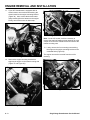
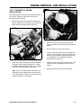
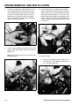
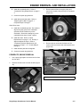
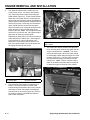
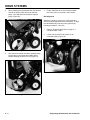
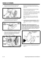
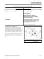
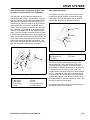
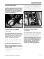
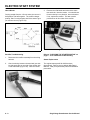
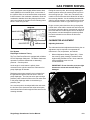
1
SINGLE STAGE SNOWTHROWER SERVICE MANUAL
Table Of Contents – Page 1 of 2
ENGINE APPLICATIONS
GENERAL INFORMATION
GENERAL SAFETY INSTRUCTIONS
IDENTIFICATION AND ORDERING
MIXING INSTRUCTIONS FOR GASOLINE AND OIL
PROPER FUEL AND OIL
OFF SEASON STORAGE
CONTROLS/LOCATION AND OPERATION
PRIMER
CHOKE
ON/OFF IGNITION SWITCH
CHECKING THE IGNITION SWITCH
VANE CONTROL - SNOW PUP - SNOWMASTER S-200 - S-620
CHUTE CONTROL
CHUTE ROTATION AND DETENT SYSTEMS
ENGINE REMOVAL AND INSTALLATION
1965 - 1985 MODELS, ENGINE REMOVAL
1965 - 1985 MODELS, ENGINE INSTALLATION
POWERLITE, ENGINE REMOVAL
POWERLITE, ENGINE INSTALLATION
20” CCR, ALL MODELS, ENGINE REMOVAL
20” CCR, ALL MODELS, ENGINE ASSEMBLY
DRIVE SYSTEMS
DRIVE SYSTEM (BELT) SNOWMASTER - S-200, S-620
BELT REPLACEMENT
BELT/PULLEY ALIGNMENT
ADJUSTING PULLEY ALIGNMENT
ENGINE PULLEY REPLACEMENT
ROTOR PULLEY REPLACEMENT
IDLER ARM / IDLER PULLEY REPLACEMENT
ASSEMBLY
20” CCR STYLE IDLER ARM
CCR2000 IDLER ARM REMOVAL
ROTOR BEARING/ ROTOR SHAFT REPLACEMENT
DRIVE SYSTEM (CHAIN) SNOW PUP - S-140
ELECTRIC START SYSTEM
INTRODUCTION
CCR POWERLITE STARTER REMOVAL
CCR 1000/TECUMSEH HSK 635 STARTER REMOVAL
20” CCR/R TEK STARTER REMOVAL
SNOWMASTER 20”, 5200 – 5620/ TECUMSEH AH520 STARTER REMOVAL
STARTER SWITCH WITH RECTIFIER TROUBLESHOOTING
TROUBLESHOOTING
CHECKING THE STARTER SWITCH
STARTER SWITCH INSPECTION
SINGLE STAGE SNOWTHROWER SERVICE MANUAL
Table Of Contents – Page 2 of 2
MAINTENANCE
WHEEL BRACKET REPLACEMENT (1975 AND OLDER MODELS)
SCRAPER REPLACEMENT
PADDLE REPLACEMENT - STRAIGHT PADDLE
REPLACING ROTOR BLADES (CURVED ROTOR MODELS)
VANE REPLACEMENT
VANE CONTROL SERVICING ON 14” AND 21” SNOWTHROWERS FROM 1965-1967
VANE CONTROL SERVICING
VANE CONTROL SERVICING: ALL 16” POWERLITE AND 20” SINGLE STAGE SNOWTHROWERS
TROUBLESHOOTING
TROUBLESHOOTING TIPS - FAILURE TO START
OLD FUEL
SPARK PLUGS
THE ENGINE RUNS BUT IT DOES NOT THROW SNOW
GAS POWER SHOVEL
GENERAL INSTRUCTIONS
PERSONAL SAFETY
BEFORE OPERATING
WHILE OPERATING
MAINTENANCE AND STORAGE
IDENTIFICATION AND ORDERING
MIXING INSTRUCTIONS FOR GASOLINE AND OIL
CONTROLS — LOCATION AND OPERATION
PRIMER OPERATION
CHOKE OPERATION
TESTING THE SWITCH
ENGINE OPERATING THEORY
CARBURETOR ADJUSTMENT
CARBURETOR SERVICE
CARBURETOR ASSEMBLY
ENGINE SERVICE
CHECKING FOR SPARK
COMPRESSION TEST
ENGINE REMOVAL
ENGINE SHORT BLOCK
FLYWHEEL REMOVAL
IGNITION TIMING/GOVERNOR
DECARBONING THE EXHAUST PORT AND THE MUFFLER
RECOIL STARTER SERVICING
DRIVE SYSTEM
REMOVING ROTOR
REPLACE SCRAPER
STORAGE
MAINTENANCE RECORD
TORO
®
Single Stage
Snowthrower
Service Manual
PREFACE
ABOUT THIS MANUAL
This manual was written expressly for the Toro brand single stage snowthrowers. The Toro
Company has made every effort to make the information in this manual complete and correct.
This manual was written with the assumption that the reader has basic mechanical and
electrical knowledge and skills. The book contains material covering snowthrowers built by The
Toro Company from 1965 through 2000, and will be specified for use on machines built after
2000 that are similar in design.
We hope that you find this manual a valuable addition to your service shop. If you have
questions or comments regarding this manual, please contact us at the following address:
The Toro Company
Consumer Service Department
8111 Lyndale Avenue South
Bloomington, MN 55420-1196
The Toro Company reserves the right to change product specifications or this manual without
notice.
COPYRIGHT© – ALL RIGHTS RESERVED
The Toro Company – 2000
Bloomington, MN 55420 – U.S.A.
TABLE OF CONTENTS
This book covers a variety of models built over several years. Look in the following Table Of Contents for the
portion of the machine that you wish to work on. Within that section we will cover each of the systems used.
ENGINE APPLICATIONS. . . . . . . . . . . . . . . . . . . . . . . . . . . . . . . . . . . . . . . . . . . . . . . . . 1 - 1
GENERAL INFORMATION
General Safety Instructions . . . . . . . . . . . . . . . . . . . . . . . . . . . . . . . . . . . . . . . . . . . . 2 - 1
Identification And Ordering . . . . . . . . . . . . . . . . . . . . . . . . . . . . . . . . . . . . . . . . . . . . . 2 - 2
Mixing Instructions For Gasoline And Oil . . . . . . . . . . . . . . . . . . . . . . . . . . . . . . . . . . 2 - 3
Proper Fuel And Oil . . . . . . . . . . . . . . . . . . . . . . . . . . . . . . . . . . . . . . . . . . . . . . . . . . 2 - 3
Off Season Storage . . . . . . . . . . . . . . . . . . . . . . . . . . . . . . . . . . . . . . . . . . . . . . . . . . 2 - 5
CONTROLS/LOCATION AND OPERATION
Primer . . . . . . . . . . . . . . . . . . . . . . . . . . . . . . . . . . . . . . . . . . . . . . . . . . . . . . . . . . . . . 3 - 2
Choke . . . . . . . . . . . . . . . . . . . . . . . . . . . . . . . . . . . . . . . . . . . . . . . . . . . . . . . . . . . . . 3 - 3
On/off Ignition Switch . . . . . . . . . . . . . . . . . . . . . . . . . . . . . . . . . . . . . . . . . . . . . . . . . 3 - 3
Checking The Ignition Switch . . . . . . . . . . . . . . . . . . . . . . . . . . . . . . . . . . . . . . . . . . . 3 - 4
Vane Control - Snow Pup - Snowmaster S-200 - S-620 . . . . . . . . . . . . . . . . . . . . . . 3 - 5
Chute Control . . . . . . . . . . . . . . . . . . . . . . . . . . . . . . . . . . . . . . . . . . . . . . . . . . . . . . . 3 - 5
Chute Rotation And Detent Systems . . . . . . . . . . . . . . . . . . . . . . . . . . . . . . . . . . . . . 3 - 6
ENGINE REMOVAL AND INSTALLATION
1965 - 1985 Models, Engine Removal . . . . . . . . . . . . . . . . . . . . . . . . . . . . . . . . . . . 4 - 1
1965 - 1985 Models, Engine Installation . . . . . . . . . . . . . . . . . . . . . . . . . . . . . . . . . . 4 - 3
Powerlite, Engine Removal . . . . . . . . . . . . . . . . . . . . . . . . . . . . . . . . . . . . . . . . . . . . 4 - 5
Powerlite, Engine Installation . . . . . . . . . . . . . . . . . . . . . . . . . . . . . . . . . . . . . . . . . . . 4 - 7
20” CCR, All Models, Engine Removal . . . . . . . . . . . . . . . . . . . . . . . . . . . . . . . . . . . 4 - 7
20” CCR, All Models, Engine Assembly . . . . . . . . . . . . . . . . . . . . . . . . . . . . . . . . . . . 4 - 9
Single Stage Snowthrower Service Manual
i
TABLE OF CONTENTS
DRIVE SYSTEMS
Drive System (Belt) Snowmaster - S-200, S-620 . . . . . . . . . . . . . . . . . . . . . . . . . . . .5 - 1
Belt Replacement . . . . . . . . . . . . . . . . . . . . . . . . . . . . . . . . . . . . . . . . . . . . . . . . . . .5 - 14
Belt/Pulley Alignment . . . . . . . . . . . . . . . . . . . . . . . . . . . . . . . . . . . . . . . . . . . . . . . .5 - 15
Adjusting Pulley Alignment . . . . . . . . . . . . . . . . . . . . . . . . . . . . . . . . . . . . . . . . . . . .5 - 15
Engine Pulley Replacement . . . . . . . . . . . . . . . . . . . . . . . . . . . . . . . . . . . . . . . . . . .5 - 15
Rotor Pulley Replacement . . . . . . . . . . . . . . . . . . . . . . . . . . . . . . . . . . . . . . . . . . . .5 - 16
Idler Arm / Idler Pulley Replacement . . . . . . . . . . . . . . . . . . . . . . . . . . . . . . . . . . . .5 - 17
Assembly . . . . . . . . . . . . . . . . . . . . . . . . . . . . . . . . . . . . . . . . . . . . . . . . . . . . . . . . .5 - 17
20” CCR Style Idler Arm . . . . . . . . . . . . . . . . . . . . . . . . . . . . . . . . . . . . . . . . . . . . . .5 - 17
CCR2000 Idler Arm Removal . . . . . . . . . . . . . . . . . . . . . . . . . . . . . . . . . . . . . . . . . .5 - 17
Rotor Bearing/ Rotor Shaft Replacement . . . . . . . . . . . . . . . . . . . . . . . . . . . . . . . .5 - 18
Drive System (Chain) Snow Pup - S-140 . . . . . . . . . . . . . . . . . . . . . . . . . . . . . . . . .5 - 19
ELECTRIC START SYSTEM
Introduction . . . . . . . . . . . . . . . . . . . . . . . . . . . . . . . . . . . . . . . . . . . . . . . . . . . . . . . . .6 - 1
CCR Powerlite Starter Removal . . . . . . . . . . . . . . . . . . . . . . . . . . . . . . . . . . . . . . . . .6 - 1
CCR 1000/Tecumseh HSK 635 Starter Removal . . . . . . . . . . . . . . . . . . . . . . . . . . . .6 - 2
20” CCR/R Tek Starter Removal . . . . . . . . . . . . . . . . . . . . . . . . . . . . . . . . . . . . . . . .6 - 4
Snowmaster 20”, 5200 – 5620/ Tecumseh AH520 Starter Removal . . . . . . . . . . . . .6 - 6
Starter Switch With Rectifier Troubleshooting . . . . . . . . . . . . . . . . . . . . . . . . . . . . . .6 - 7
Troubleshooting . . . . . . . . . . . . . . . . . . . . . . . . . . . . . . . . . . . . . . . . . . . . . . . . . . . . .6 - 9
Checking The Starter Switch . . . . . . . . . . . . . . . . . . . . . . . . . . . . . . . . . . . . . . . . . .6 - 10
Starter Switch Inspection . . . . . . . . . . . . . . . . . . . . . . . . . . . . . . . . . . . . . . . . . . . . .6 - 10
ii
Single Stage Snowthrower Service Manual
TABLE OF CONTENTS
MAINTENANCE
Wheel Bracket Replacement (1975 And Older Models) . . . . . . . . . . . . . . . . . . . . . . 7 - 1
Scraper Replacement . . . . . . . . . . . . . . . . . . . . . . . . . . . . . . . . . . . . . . . . . . . . . . . . 7 - 1
Paddle Replacement - Straight Paddle . . . . . . . . . . . . . . . . . . . . . . . . . . . . . . . . . . . 7 - 2
Replacing Rotor Blades (Curved Rotor Models) . . . . . . . . . . . . . . . . . . . . . . . . . . . . 7 - 4
Vane Replacement . . . . . . . . . . . . . . . . . . . . . . . . . . . . . . . . . . . . . . . . . . . . . . . . . . . 7 - 6
Vane Control Servicing On 14” And 21” Snowthrowers From 1965-1967 . . . . . . . . . 7 - 7
Vane Control Servicing . . . . . . . . . . . . . . . . . . . . . . . . . . . . . . . . . . . . . . . . . . . . . . . 7 - 7
Vane Control Servicing: All 16” Powerlite And 20” Single Stage Snowthrowers . . . . 7 - 8
TROUBLESHOOTING
Troubleshooting Tips - Failure To Start . . . . . . . . . . . . . . . . . . . . . . . . . . . . . . . . . . . 8 - 1
Old Fuel . . . . . . . . . . . . . . . . . . . . . . . . . . . . . . . . . . . . . . . . . . . . . . . . . . . . . . . . . . . 8 - 1
Spark Plugs . . . . . . . . . . . . . . . . . . . . . . . . . . . . . . . . . . . . . . . . . . . . . . . . . . . . . . . . 8 - 3
The Engine Runs But It Does Not Throw Snow . . . . . . . . . . . . . . . . . . . . . . . . . . . . . 8 - 3
GAS POWER SHOVEL
General Instructions . . . . . . . . . . . . . . . . . . . . . . . . . . . . . . . . . . . . . . . . . . . . . . . . . . 9 - 1
Personal Safety . . . . . . . . . . . . . . . . . . . . . . . . . . . . . . . . . . . . . . . . . . . . . . . . . . . . . 9 - 1
Before Operating . . . . . . . . . . . . . . . . . . . . . . . . . . . . . . . . . . . . . . . . . . . . . . . . . . . . 9 - 1
While Operating . . . . . . . . . . . . . . . . . . . . . . . . . . . . . . . . . . . . . . . . . . . . . . . . . . . . . 9 - 1
Maintenance And Storage . . . . . . . . . . . . . . . . . . . . . . . . . . . . . . . . . . . . . . . . . . . . . 9 - 2
Identification And Ordering . . . . . . . . . . . . . . . . . . . . . . . . . . . . . . . . . . . . . . . . . . . . . 9 - 2
Mixing Instructions For Gasoline And Oil . . . . . . . . . . . . . . . . . . . . . . . . . . . . . . . . . . 9 - 3
Controls — Location And Operation . . . . . . . . . . . . . . . . . . . . . . . . . . . . . . . . . . . . . 9 - 5
Single Stage Snowthrower Service Manual
iii
TABLE OF CONTENTS
Primer Operation . . . . . . . . . . . . . . . . . . . . . . . . . . . . . . . . . . . . . . . . . . . . . . . . . . . .9 - 6
Choke Operation . . . . . . . . . . . . . . . . . . . . . . . . . . . . . . . . . . . . . . . . . . . . . . . . . . . .9 - 6
Testing The Switch . . . . . . . . . . . . . . . . . . . . . . . . . . . . . . . . . . . . . . . . . . . . . . . . . . .9 - 6
Engine Operating Theory . . . . . . . . . . . . . . . . . . . . . . . . . . . . . . . . . . . . . . . . . . . . . .9 - 7
Carburetor Adjustment . . . . . . . . . . . . . . . . . . . . . . . . . . . . . . . . . . . . . . . . . . . . . . . .9 - 9
Carburetor Service . . . . . . . . . . . . . . . . . . . . . . . . . . . . . . . . . . . . . . . . . . . . . . . . . .9 - 10
Carburetor Assembly . . . . . . . . . . . . . . . . . . . . . . . . . . . . . . . . . . . . . . . . . . . . . . . .9 - 12
Engine Service . . . . . . . . . . . . . . . . . . . . . . . . . . . . . . . . . . . . . . . . . . . . . . . . . . . . .9 - 14
Checking For Spark . . . . . . . . . . . . . . . . . . . . . . . . . . . . . . . . . . . . . . . . . . . . . . . . .9 - 15
Compression Test . . . . . . . . . . . . . . . . . . . . . . . . . . . . . . . . . . . . . . . . . . . . . . . . . .9 - 16
Engine Removal . . . . . . . . . . . . . . . . . . . . . . . . . . . . . . . . . . . . . . . . . . . . . . . . . . . .9 - 16
Engine Short Block . . . . . . . . . . . . . . . . . . . . . . . . . . . . . . . . . . . . . . . . . . . . . . . . . .9 - 17
Flywheel Removal . . . . . . . . . . . . . . . . . . . . . . . . . . . . . . . . . . . . . . . . . . . . . . . . . .9 - 19
Ignition Timing/Governor . . . . . . . . . . . . . . . . . . . . . . . . . . . . . . . . . . . . . . . . . . . . .9 - 19
Decarboning The Exhaust Port And The Muffler . . . . . . . . . . . . . . . . . . . . . . . . . . .9 - 20
Recoil Starter Servicing . . . . . . . . . . . . . . . . . . . . . . . . . . . . . . . . . . . . . . . . . . . . . .9 - 20
Drive System . . . . . . . . . . . . . . . . . . . . . . . . . . . . . . . . . . . . . . . . . . . . . . . . . . . . . .9 - 21
Removing Rotor . . . . . . . . . . . . . . . . . . . . . . . . . . . . . . . . . . . . . . . . . . . . . . . . . . . .9 - 22
Replace Scraper . . . . . . . . . . . . . . . . . . . . . . . . . . . . . . . . . . . . . . . . . . . . . . . . . . . .9 - 23
Storage . . . . . . . . . . . . . . . . . . . . . . . . . . . . . . . . . . . . . . . . . . . . . . . . . . . . . . . . . . .9 - 23
Maintenance Record . . . . . . . . . . . . . . . . . . . . . . . . . . . . . . . . . . . . . . . . . . . . . . . .9 - 28
iv
Single Stage Snowthrower Service Manual
TABLE OF CONTENTS
ENGINES
Several different engines have been used on the single stage snowthrower product line. Refer to the chart
beginning on page 1 - 1 to determine the engine manufacturer. Engine manuals may be obtained from the
following sources.
Tecumseh Products Co.
900 North St.
Grafton, WI 53024
Tecumseh Engine Models:
• AH520, AH600, HSK600
Toro Engines:
Order the following service manuals through any Authorized Toro Service Dealer:
•
Model 38350 Gas Power Shovel (the engine is covered in this book).
•
Toro 47P series - Use Toro manual 492-0260.
•
Toro R tek (E engine) series - Use Toro manual 492-0647.
Single Stage Snowthrower Service Manual
v
THIS PAGE INTENTIONALLY LEFT BLANK
vi
Single Stage Snowthrower Service Manual
ENGINE APPLICATIONS
Model #
Model Name
Width
Years of Mfg
Eng Mfg
Eng Model
Mix Ratio
Max RPM
Spark Plug *
Gap (in.)
31405
Snow Pup
14”
1976-1977
Tec.
AH520
32:1
4100-4500
Champion
RJ18YC
.035
31410
Snow Pup
14"
1966-1967
Tec.
AH520
16:1
4300-4700
Champion
RJ18YC
.035
31411
Snow Pup
14"
1968-1971
Tec.
AH520
16:1
4100-4500
Champion
RJ18YC
.035
31412
Snow Pup
14"
1972-1975
Tec.
AH520
16:1
4300-4700
Champion
RJ18YC
.035
31500
Snow Husky
21"
1966-1967
Tec.
AH520
16:1
4300-4700
Champion
RJ18YC
.035
31501
Snow Pup
21”
1968-1971
Tec.
AH520
16:1
4300-4700
Champion
RJ18YC
.035
31502
Snow Pup
21"
1972-1974
Tec.
AH520
16:1
4300-4700
Champion
RJ18YC
.035
31505
Snowmaster
20"
1975
Tec.
AH520
32:1
4100-4500
Champion
RJ18YC
.035
31506
Snowmaster
20"
1976-1977
Tec.
AH520
32:1
4100-4500
Champion
RJ18YC
.035
38014
Snowmaster
14”
1978
Tec.
AH520
32:1
4100-4500
Champion
RJ18YC
.035
38020
Snowmaster
20"
1978
Tec.
AH520
32:1
4100-4500
Champion
RJ18YC
.035
38030
Snowmaster
20"
1978
Tec.
AH520
32:1
4100-4500
Champion
RJ18YC
.035
38100
S140
14"
1979-1981
Tec.
AH520
32:1
4100-4500
Champion
RJ18YC
.035
38110C
CR20
20"
1987-1990
Tec.
AH600
32:1
4300-4500
Champion
RCJ8Y
.030
38111C
CR20
20"
1987
Tec.
AH600
32:1
4300-4500
Champion
RCJ8Y
.030
38115C
CR20
20"
1987-1990
Tec.
AH600
32:1
4300-4700
Champion
RCJ8Y
.030
38116
CR20
20"
1988-1989
Tec.
AH600
32:1
4300-4700
Champion
RCJ8Y
.030
38116C
CR20
20"
1987
Tec.
AH600
32:1
4300-4700
Champion
RCJ8Y
.030
38120
S200
20"
1979-1984
Tec.
AH520
32:1
4100-4500
Champion
RJ18YC
.035
38130
S200
20"
1979-1981
Tec.
AH520
32:1
4100-4500
Champion
RJ18YC
.035
38162
S620
20"
1984-1991
Tec.
AH600
32:1
4300-4700
Champion
RCJ8Y
.030
38162C
S620
20"
1984-1986
Tec.
AH600
32:1
4300-4700
Champion
RCJ8Y
.030
38165
S620
20"
1985-1991
Tec.
AH600
32:1
4300-4700
Champion
RCJ8Y
.030
38165C
S620
20"
1986
Tec.
AH600
32:1
4300-4700
Champion
RCJ8Y
.030
38167C
S620
20"
1986
Tec.
AH600
32:1
4300-4700
Champion
RCJ8Y
.030
38170
Powerlite
16"
1991-2000
Tec.
HSK600
50:1
4300-4700
Champion
RCJ8Y
.030
38171
Powerlite
16"
1992-1998
Tec.
HSK600
50:1
4300-4700
Champion
RCJ8Y
.030
38172
Powerlite
16"
2000
Tec.
HSK600
50:1
4300-4700
Champion
RCJ8Y
.030
Single Stage Snowthrower Service Manual
1-1
ENGINE APPLICATIONS
Model #
Model Name
Width
Years of Mfg
Eng Mfg
Eng Model
Mix Ratio
Max RPM
Spark Plug *
Gap (in.)
38173
Powerlite
16"
2000
Tec.
HSK600
50:1
4300-4700
Champion
RCJ8Y
.030
38175
Powerlite
16"
1991-1999
Tec.
HSK600
50:1
4300-4700
Champion
RCJ8Y
.030
38176
Powerlite
16"
1992-1998
Tec.
HSK600
50:1
4300-4700
Champion
RCJ8Y
.030
38177
Powerlite
16"
1999
Tec.
HSK600
50:1
4300-4700
Champion
RCJ8Y
.030
38178
Powerlite
16"
1999
Tec.
HSK600
50:1
4300-4700
Champion
RCJ8Y
.030
38180
CCR2000
20"
1986-1996
Toro
47P**
50:1
3550-3850
NGK BPMR4A
.032
38180C
CCR2000
20"
1987-1989
Toro
47P**
50:1
3550-3850
NGK BPMR4A
.032
38181
CCR2000
20"
1990-1996
Toro
47P**
50:1
3550-3850
NGK BPMR4A
.032
38182
Powerlite
16"
2000
Tec.
HSK600
50:1
4300-4700
Champion
RCJ8Y
.030
38183
Powerlite
16"
2000
Tec.
HSK600
50:1
4300-4700
Champion
RCJ8Y
.030
38185
CCR2000
20"
1987-1996
Toro
47P**
50:1
3550-3850
NGK BPMR4A
.032
38185C
CCR2000
20"
1988-1998
Toro
47P**
50:1
3550-3850
NGK BPMR4A
.032
38186
CCR2000
20"
1990-1996
Toro
47P**
50:1
3550-3850
NGK BPMR4A
.032
38190
CCR1000
20"
1990-1996
Tec.
HSK600
50:1
4300-4700
Champion
RCJ8Y
.030
38191
CCR1000
20"
1992-1996
Tec.
HSK600
50:1
4300-4700
Champion
RCJ8Y
.030
38195
CCR1000
20"
1990-1996
Tec.
HSK600
50:1
4300-4700
Champion
RCJ8Y
.030
38196
CCR1000
20"
1992-1996
Tec.
HSK600
50:1
4300-4700
Champion
RCJ8Y
.030
38210
S140
14"
1979-1980
Tec.
AH520
32:1
4100-4500
Champion
RJ18YC
.035
38220
S200
20"
1979
Tec.
AH520
32:1
4100-4500
Champion
RJ18YC
.035
38225
S200
20"
1980
Tec.
AH520
32:1
4100-4500
Champion
RJ18YC
.035
38230
S200
20"
1979
Tec.
AH520
32:1
4100-4500
Champion
RJ18YC
.035
38232
S200
20"
1981-1985
Tec.
AH520
32:1
4100-4500
Champion
RJ18YC
.035
38235
S200
20"
1980-1983
Tec.
AH520
32:1
4100-4500
Champion
RJ18YC
.035
38242
S200
20"
1981-1983
Tec.
AH520
32:1
4100-4500
Champion
RJ18YC
.035
38252
S200
20"
1981
Tec.
AH520
32:1
4100-4500
Champion
RJ18YC
.035
38350
Gas Power Shovel
14"
1983-1985
Toro
NA
32:1
7800-8800
Champion
RCJ8
.022
38400
CCR1000
20"
1999-2000
Tec.
HSK635
50:1
4300-4700
Champion
RCJ8Y
.030
38405
CCR1000
20"
1999-2000
Tec.
HSK635
50:1
4300-4700
Champion
RCJ8Y
.030
38409
CCR2400
20"
1998-1999
Toro
R tek
50:1
3450-3950
NGK BPMR4A
.032
38410
CCR2400
20"
1997
Tec.
HSK850
50:1
3550-3850
Champion
RCJ8Y
.030
38411
CCR2400
20"
1997
Tec.
HSK850
50:1
3550-3850
Champion
RCJ8Y
.030
38412
CCR2400
20"
1998-1999
Toro
R tek
50:1
3450-3950
NGK BPMR4A
.032
1-2
Single Stage Snowthrower Service Manual
ENGINE APPLICATIONS
Model #
Model Name
Width
Years of Mfg
Eng Mfg
Eng Model
Mix Ratio
Max RPM
Spark Plug *
Gap (in.)
38413
CCR2450
20"
2000
Toro
R tek
50:1
3550-4050
NGK BPMR4A
.032
38414
CCR2400
20"
1998-1999
Toro
R tek
50:1
3450-3950
NGK BPMR4A
.032
38415
CCR2400
20"
1997
Tec.
HSK850
50:1
3550-3850
Champion
RCJ8Y
.030
38416
CCR2400
20"
1997
Tec.
HSK850
50:1
3550-3850
Champion
RCJ8Y
.030
38417
CCR2400
20"
1998
Toro
R tek
50:1
3450-3950
NGK BPMR4A
.032
38418
CCR2400
20"
1999
Toro
R tek
50:1
3450-3950
NGK BPMR4A
.032
38419
CCR2450
20"
2000
Toro
R tek
50:1
3550-4050
NGK BPMR4A
.032
38420
CCR2500
20"
1997
Tec.
HSK850
50:1
3550-3850
Champion
RCJ8Y
.030
38421
CCR2500
20"
1997
Tec.
HSK850
50:1
3550-3850
Champion
RCJ8Y
.030
38422
CCR2500
20"
1998-1999
Toro
R tek
50:1
3550-4050
NGK BPMR4A
.032
38423
CCR2500
20"
1998
Toro
R tek
50:1
3550-4050
NGK BPMR4A
.032
38424
CCR2500
20"
1998-1999
Toro
R tek
50:1
3550-4050
NGK BPMR4A
.032
38425
CCR2500
20"
1997
Tec.
HSK850
50:1
3550-3850
Champion
RCJ8Y
.030
38426
CCR2500
20"
1997
Tec.
HSK850
50:1
3550-3850
Champion
RCJ8Y
.030
38427
CCR2500
20"
1998
Toro
R tek
50:1
3550-4050
NGK BPMR4A
.032
38428
CCR2450
20"
2000
Toro
R tek
50:1
3550-4050
NGK BPMR4A
.032
38429
CCR2450
20"
2000
Toro
R tek
50:1
3550-4050
NGK BPMR4A
.032
38430
CCR3000
20"
1997-1999
Toro
47P**
50:1
3550-3850
NGK BPMR4A
.032
38431
CCR3000
20"
1997-1998
Toro
47P**
50:1
3550-3850
NGK BPMR4A
.032
38432
CCR3000
20"
1999
Toro
R tek
50:1
3650-4150
NGK BPMR4A
.032
38433
CCR3000
20"
1999
Toro
R tek
50:1
3650-4150
NGK BPMR4A
.032
38435
CCR3000
20"
1997-1999
Toro
47P**
50:1
3550-3850
NGK BPMR4A
.032
38436
CCR3000
20"
1997-1998
Toro
47P**
50:1
3550-3850
NGK BPMR4A
.032
38437
CCR3000
20"
1999
Toro
R tek
50:1
3650-4150
NGK BPMR4A
.032
38438
CCR3000
20"
1999
Toro
R tek
50:1
3650-4150
NGK BPMR4A
.032
38439
CCR3600
20"
2000
Toro
R tek
50:1
3650-4150
NGK BPMR4A
.032
38440
CCR3650
20"
2000
Toro
R tek
50:1
3750-4250
NGK BPMR4A
.032
38441
CCR3650
20"
2000
Toro
R tek
50:1
3750-4250
NGK BPMR4A
.032
38442
CCR3650
20"
2000
Toro
R tek
50:1
3750-4250
NGK BPMR4A
.032
38445
CCR3650
20"
2000
Toro
R tek
50:1
3750-4250
NGK BPMR4A
.032
* RJ18YC replaces RJ18Y
Single Stage Snowthrower Service Manual
1-3
THIS PAGE INTENTIONALLY LEFT BLANK
1-4
Single Stage Snowthrower Service Manual
GENERAL INFORMATION
GENERAL SAFETY INSTRUCTIONS
This safety alert symbol means CAUTION
- PERSONAL SAFETY INSTRUCTION.
Read the instruction because it has to do
with safety. Failure to comply with the instruction
may result in personal injury.
Personal Safety
•
Never allow children to operate the snowthrower.
Adults should operate the snowthrower only after
reading the owner’s manual and receiving proper
instructions.
•
Keep everyone, especially children and pets, away
from the area of operation.
•
Wear adequate winter clothing and footwear that
will improve footing on slippery surfaces.
•
Keep face, hands, feet, and other parts of your
body or clothing away from concealed, moving, or
rotating parts. Stay behind the handle while
operating the snowthrower. STAY CLEAR OF
DISCHARGE OPENING AT ALL TIMES.
•
Do not attempt to make adjustments while engine
is running.
•
Use extreme caution when clearing snow from
walk, road, or a gravel drive. Push down on the
handle to raise skid and impeller blades to avoid
picking up rocks and throwing them. Stay alert for
hidden hazards and traffic on roads.
•
Never direct discharge of the snowthrower at
bystanders, glass enclosures, automobiles, trucks,
and window wells. Keep children and pets away.
•
If a solid object is hit or if the snowthrower vibrates
abnormally, turn key to OFF so engine stops.
Next, remove high tension wire from the spark
plug; then check snowthrower for possible
damage, an obstruction, or loose parts. Repair
damage before starting and operating the
snowthrower.
•
Before adjusting, cleaning, repairing, or inspecting
the snowthrower, and before unclogging the
discharge guide, shut engine off and wait for all
moving parts to stop. Next remove high tension
wire from spark plug, and keep wire away from
plug to prevent accidental starting.
•
Use caution when operating snowthrower as the
exhaust pipe is hot and could cause personal injury
or damage to clothing.
Before Operating
•
Familiarize yourself with the controls. Know how to
stop the engine and disengage controls quickly.
•
Since fuel is highly flammable, handle it with care.
Fill the fuel tank with a mixture of gasoline and oil
before trying to start the engine.
•
Use an approved fuel container for storing the
gasoline/oil mixture. Store fuel outside unless it is
stored in a fireproof cabinet.
•
Fill fuel tank outdoors, not indoors. The fuel tank
must not be filled when engine is running or when
engine is hot.
•
Install the gasoline container cap, fuel tank cap,
and wipe up any spilled gasoline before starting the
engine.
•
Keep all shields and safety devices in place. If a
shield or safety device is defective, make all
repairs before operating the snowthrower. Also
tighten all nuts, bolts, and screws.
During Operation
•
•
Never operate the snowthrower without good
visibility or light. Always maintain a secure footing
and keep a firm grip on the handle when clearing
snow: WALK, NEVER RUN. DO NOT USE
SNOWTHROWER ON A ROOF.
Electric Start Safety Precautions
•
Use the extension cord provided with the Electric
Start (P.N. 28-9170) or any 16 gauge 2 or 3 wire
cord.
•
Do not plug the extension cord into the outlet while
standing in water or when hands are wet.
•
Do not use or connect the cord if gasoline has
been spilled on it.
•
Always replace a damaged extension cord
immediately.
•
Authorized Toro Service Dealers are certified for
electrical repairs and electrical servicing. Do not
attempt to repair 110V products.
Do not run the engine indoors.
Single Stage Snowthrower Service Manual
2-1
GENERAL INFORMATION
Storage During Snow Season
•
When storing the snowthrower, REMOVE THE
KEY FROM SWITCH. Store the key in a
memorable place.
•
Never leave gasoline in a snowthrower fuel tank
when snowthrower is stored in a building where a
flame or spark may be present. Allow the engine to
cool before storing. Never store a snowthrower in
the house or basement because of potential fire
hazard.
•
Before performing any maintenance or servicing to
the snowthrower, turn key to OFF and wait for
engine and all moving parts to stop. Remove the
key switch and pull high tension wire from spark
plug.
•
Reinstall the fuel cap when the top cover is
removed for maintenance procedures. Perform
maintenance and use storage instructions
described in this manual.
•
Keep all nuts, bolts, and screws tight to assure
snowthrower is in safe working condition. Be sure
to check the rotor and the engine mounting bolts.
•
ALWAYS USE TORO REPLACEMENT PARTS
AND ACCESSORIES TO ASSURE SAFETY AND
OPTIMUM PERFORMANCE. NEVER USE
“WILL-FIT” REPLACEMENT PARTS AND
ACCESSORIES.
14” and 21” Models
Figure 1
0217-001
Location: Right side of the square tubing on the main
frame. Shroud will need removal to read.
20” Models
Figure 2
0217-002
Location: Right side of the impeller housing just ahead
of the right wheel.
IDENTIFICATION AND ORDERING
IDENTIFICATION:
All Toro Products, including single stage
snowthrowers, have two identification numbers: a
model number and serial number. In any
correspondence concerning your snowthrower, always
supply the model and serial number, to assure the
correct information or replacement parts are obtained.
The two numbers are stamped on a decal, which are
located in various places on the snowthrowers. The
location will vary depending on the model and year the
unit was manufactured. Please note the diagrams to
determine the location of the model and serial number
decal on your unit (Figure 1 through Figure 3).
A
Figure 3
0530-01
(A) Model and Serial Number Decal
2-2
Single Stage Snowthrower Service Manual
GENERAL INFORMATION
ORDERING: Toro parts are available through your
local Authorized Toro Service Dealer.
MIXING INSTRUCTIONS FOR GASOLINE
AND OIL
NOTE: To find the nearest Authorized Toro Service
Dealer in your area, please consult your yellow pages
under “lawn mowers” or “snowthrowers”.
Safety Instructions
Parts:
To order replacement parts from an authorized TORO
Dealer, the following information is needed:
1.
Model and serial number of the snowthrower.
2.
Description of the part(s) and quantity of part(s)
desired. If a parts manual is being used, use the
PART NUMBER and the description.
Manuals:
Should a replacement owner’s manual or parts manual
be needed, please send the complete model and serial
number along with your name and address to:
The Toro Company
8111 Lyndale Avenue South
Minneapolis, MN 55420
ATTN: Parts Department
CAUTION
Gasoline is flammable and caution must be used
when handling or storing it. Do not fill the fuel
tank while snowthrower is running, while it is hot,
or when it is in an enclosed area. Keep away from
an open flame, an electrical spark, and DO NOT
SMOKE while mixing fuel or filling the fuel tank.
Fill the fuel tank to within 1/4 - 1/2 inch from top of
the tank to provide space for expansion of fuel.
Never fill the fuel tank to the top of filler neck.
Always fill the fuel tank outdoors and use a funnel
or spout to prevent spilling. Make sure to wipe up
any spilled fuel before starting the engine.
Store gasoline in a clean, approved container, and
keep the cap in place on the container. Keep
gasoline in a cool, well ventilated place; never in
the house. Never buy more than a 30 day supply
of gasoline to assure volatility. Gasoline is
intended to be used as a fuel for internal
combustion engines; therefore, do not use
gasoline for any other purpose. Since many
children like the smell of gasoline, keep it out of
their reach because the fumes are dangerous to
inhale, as well as being explosive.
PROPER FUEL AND OIL
Three basic engine configurations have been used in
this product group. Due to internal differences, there
are three different fuel/oil mix ratios. See the charts on
page 2 - 4 and 2 - 5 for the proper ratio for your model.
Mixing Procedures
Use the following procedures to assure the fuel is
properly mixed:
Single Stage Snowthrower Service Manual
1.
Add 1 quart of unleaded REGULAR gasoline to a
gasoline container.
2.
If your snowthrower requires a 16:1 gas to oil
ratio; pour one cup or 8 ounces of Toro 2-cycle
engine oil into the gasoline container (Figure 4).
2-3
GENERAL INFORMATION
3.
If your unit requires a gasoline/oil ratio of 32:1,
pour 1/2 cup or 4 ounces of TORO 2-cycle engine
oil into the gasoline container (Figure 5).
Do not store the oil near an open flame or in an
extremely warm environment as the oil is
flammable.
4.
If your snowthrower requires a 50:1 gas to oil
ratio; pour 2.6 oz. of Toro 2-cycle oil into the
gasoline container (Figure 6).
5.
Shake the gasoline container vigorously so oil
mixes with gasoline. Remember to install cap on
gasoline container before shaking.
6.
Add an additional 3 quarts of gasoline to the
premixed gasoline. Fuel mixture is now ready to
use in your snowthrower.
Mix With One U.S. Gallon
Ratio
Oil
16:1
8 oz.
32:1
4 oz.
50:1
2.6 oz.
CAUTION
IMPORTANT: If the fuel and Toro 2-cycle oil are not
mixed at the correct ratio for your snowthrower,
(either 16:1, 32:1, or 50:1) piston damage and other
engine damage may occur. It is important that the
fuel and oil be mixed at temperatures above 40° F
to ensure complete mixing.
Note: To assure the fuel and oil mixes completely,
store your Toro 2-cycle Oil indoors, so it will be at room
temperature (above 50° F).
Filling The Fuel Tank
IMPORTANT: Do not fill the fuel tank with gasoline
that has not been mixed with Toro 2-cycle engine
oil in the correct ratio for your snowthrower. Do
not use gasoline additives, engine damage could
result.
16:1 RATIO MIX
OIL
(1 CUP OR 8 OZ.) (0.236 l)
GAS
(1 U.S. QUART (0.946 l)
SHAKE
CAN
GASOLINE CONTAINER
ADD
MORE
GAS
(3 U.S. QUARTS)
(2.84 l)
GASOLINE CONTAINER
Figure 4
32:1 RATIO MIX
OIL
(1/2 CUP OR 4 OZ.) (0.118 l)
GAS
(1 U.S. QUART (0.946 l)
SHAKE
CAN
GASOLINE CONTAINER
ADD
MORE
GAS
(3 U.S. QUARTS)
(2.84 l)
GASOLINE CONTAINER
Figure 5
2-4
Single Stage Snowthrower Service Manual
GENERAL INFORMATION
50:1 RATIO MIX
OIL
(1/3 CUP OR 2.6 OZ.) (0.079 l)
GAS
(1 U.S. QUART (0.946 l)
ADD
MORE
GAS
(3 U.S. QUARTS)
(2.84 l)
SHAKE
CAN
GASOLINE CONTAINER
GASOLINE CONTAINER
Figure 6
1.
Mix the gasoline and oil in the correct ratio for your
unit. Refer to “MIXING INSTRUCTIONS FOR
GASOLINE AND OIL” on page 2 - 3.
2.
Clean the area around snowthrower fuel tank cap
so foreign matter does not get into the fuel tank.
Remove the cap from the fuel tank.
3.
Fill snowthrower fuel tank to within 1/4 - 1/2 inch
from the top of the tank, not the filler neck.
4.
Install the cap securely on snowthrower fuel tank.
Draining The Fuel Tank
CAUTION
Because the gasoline/oil mixture in the
snowthrower fuel tank is explosive, the fuel
mixture must be drained outdoors, away from fire
and flame. Do not smoke while draining gasoline.
To assure safe servicing of your snowthrower, it is
critical that the fuel tank be drained. To drain the fuel
tank on your snowthrower, use the following procedure:
1.
Use a pump type siphon to remove as much fuel
from the tank as possible. Dispose of fuel
properly. One method of disposing of left over fuel
is to put it in the car. If you have a half tank of fuel
in the car, a gallon or two of fuel mix will blend with
the gas and have no effect. If the fuel is extremely
old and does not smell like gasoline, we would not
recommend its use in any engine. Contact your
local authorities for disposal instructions.
Single Stage Snowthrower Service Manual
2.
Use the primer and choke and start the engine. It
should run several minutes to consume the fuel in
the carburetor and fuel line. When the engine
stops, attempt to start it again. Use the primer
and choke. The engine may start and stop 2 or 3
times. Repeat until you cannot start the engine.
Note: Draining the fuel tank and letting the
unit run out of fuel is a critical servicing
procedure when preparing your snowthrower
for storage. Expending fuel from the engine
will prevent gum-like varnish deposits from
forming in the carburetor, fuel line, and fuel
tank. Such deposits, if allowed to form, will
cause starting problems the following season.
OFF SEASON STORAGE
CAUTION
Because gasoline/oil mixture in the snowthrower
fuel tank is explosive, the fuel mixture must be
drained outdoors, away from fire and flame. Do
not smoke while draining gasoline. If fuel mixture
explodes, personal injury may result.
Properly preparing the machine for off season storage
is the single most important thing that can be done to
prevent problems. The summer heat will rapidly
evaporate fuel in the tank and carburetor. Dried fuel in
the carburetor can and often does plug the fuel
passages and prevent starting the following snow
season. We recommend the use of a petroleum based
fuel stabilizer during the snow season. The stabilizer
will help keep fuel fresh and assist with starting.
2-5
GENERAL INFORMATION
1.
Use a pump type siphon to remove as much fuel
from the tank as possible. Dispose of fuel
properly. One method of disposing of left over fuel
is to put it in the car. If you have a half tank of fuel
in the car, a gallon or two of fuel mix will blend with
the gas and have no affect. If the fuel is extremely
old and does not smell like gasoline, we would not
recommend its use in any engine. Contact your
local authorities for disposal instructions.
2.
Use the primer and choke and start the engine. It
should run several minutes to consume the fuel in
the carburetor and fuel line. When the engine
stops, attempt to start it again. Use the primer
and choke. The engine may start and stop 2 or 3
times. Repeat until you cannot start the engine.
3.
With the key off, slowly pull the starter rope until
resistance is felt, release the starter rope.
4.
Tighten loose nuts and bolts.
5.
On the 14” models with chain drive (Snow Pup),
remove the chain guard and lightly oil the chain
with 30 wt. engine oil. Install the chain guard.
6.
Store the machine in a clean dry area, cover if you
wish. (DO NOT store any gasoline powered
machine in the house, basement, or near any
appliance that contains fire or flame.)
7.
Remove the key and place in a memorable place.
2-6
Single Stage Snowthrower Service Manual
CONTROLS/LOCATION AND OPERATION
The primer and choke controls have been located in
different areas throughout the years. Figure 7, Figure
8, Figure 9, and show the various locations.
B
A
Figure 9
(A) Choke
Figure 7
0217-004
B
1854-28
(B) Primer
The ignition switch has been located in the same
position on the control panel since introduction of the
1975 Snowmaster (Figure 8). Prior to 1975, the unit’s
engine was stopped by depressing the spark plug kill
lever. This lever was located below a translucent boot
on the upper shroud. The lever would ground the
spark to frame of the snowthrower when depressed
(Figure 10). Press and hold until the engine stops
completely.
A
Figure 8
(A) Primer
0217-005
(B) Choke
Figure 10
Single Stage Snowthrower Service Manual
0217-006
3-1
CONTROLS/LOCATION AND OPERATION
PRIMER
The primer, used on most single stage snowthrowers,
is designed to pump a small amount of fuel from the
carburetor into the carburetor throat. This extra fuel
mixture allows the engine to be started in cold
temperatures.
The primer is operated by depressing the primer bulb
with a finger, ensuring the finger covers the vent hole in
the bulb. Depress the primer button, release, wait
about 3 seconds, then depress the primer again.
Repeat as often as needed. The pause in between
primes allows time for the prime well in the carburetor
to refill.
Operator priming instructions vary depending on the
year your snowthrower was manufactured. On those
units manufactured from 1972 and before, in a cold
start application, the primer should be pressed
approximately 10 times (Figure 11). The 1973 through
1977 single stage snowthrower primer should be
pressed 5 times. Snowthrowers produced from 1978
through 1980, the primer should be pushed one to four
times (Figure 8, Figure 11, or Figure 12). For
temperatures above +20° F (-7° C) use one or two
primes; below +20° F (-7° C) use three or four primes.
For extremely cold temperatures below -10° F (-23° C)
use five or six primes. For 1981 and newer models,
depress the primer one or two times, with a pause in
between. Additional primes may be necessary in
colder temperatures.
Note: On early production, the diaphragm cover was
vented, and on later production, the primer bulb
incorporates the vent. Those models with a vented
diaphragm cover require more primes.
Figure 11
0217-007
Figure 12
0217-008
PRIMING CHART
Number of times primer is
depressed
Years
3-2
1965-1972
10
1973- 1977
5
1978- 1980
1-4
1981 - Up
1-2
Single Stage Snowthrower Service Manual
CONTROLS/LOCATION AND OPERATION
CHOKE
The carburetor choke control, or shutter, meters the
amount of air passing into the engine. When starting
the engine, the carburetor choke should be closed
(Figure 13). If your snowthrower has either the choke
cable, choke rod, or handle design to close the choke
shutter, the cable, rod, or handle should be pulled out.
If you have a single stage snowthrower manufactured
in 1980, the choke control should be rotated clockwise
to close the shutter, counterclockwise to open the
shutter.
Figure 14
0217-010
After the engine starts, more air must pass into the
engine. Therefore, after the engine is started, open the
choke shutter to allow more air to pass into the engine.
Again, to open the choke shutter on those models that
have a choke cable, rod, or handle, push the choke
control lever in. On 1980 snowthrowers, the choke
control lever should be rotated counterclockwise.
Figure 13
0217-009
Closing the choke shutter allows air to enter the
carburetor only through openings in and around the
choke shutter (Figure 14). When the engine is
cranked, a low pressure area is created in the engine
and it extends into the carburetor. Since only a limited
amount of air can enter this low pressure area because
of the closed choke shutter, a greater amount of fuel is
drawn through the fuel passages to fill the void. This
creates the richer mixture needed for engine starting
and restarting after the engine is warm.
Single Stage Snowthrower Service Manual
THROTTLE: On Toro applications, the carburetor
throttle is controlled by the governor only. Therefore,
Toro single stage snowthrowers, are not equipped with
an engine speed control for the operator.
ON/OFF IGNITION SWITCH
The ignition switch found on Toro single stage
snowthrowers produced since 1975, allows the engine
to be started when the key is in the ON position.
Rotating the key to the OFF position will stop the
engine by allowing magneto current to flow to ground
(Figure 12).
3-3
CONTROLS/LOCATION AND OPERATION
CHECKING THE IGNITION SWITCH
CONTINUITY CHART FOR SWITCHING
The tools used to check for defective switches are a
continuity tester/light or an ohmmeter (Figure 15). A
continuity tester or ohmmeter, as the names imply, are
used to test for a completed current flow in an electrical
circuit. To test the ignition switch on your snowthrower:
Figure 15
Continuity Light
light off
light on
Remove the upper shroud.
2.
Slide the terminal connector off the ignition switch
(Figure 16). With the key in the OFF position,
place the continuity light or ohmmeter leads, one
to each terminal on the ignition switch (Figure 17);
the light or meter, depending on the instrument
used, should show continuity. (The continuity light
should be on or the ohmmeter needle should
move to a zero ohms reading.) If not, the switch is
defective and needs to be replaced.
Figure 17
0217-013
Now, turn the key to the ON position, the meter or
light from the tester should not indicate continuity
(Figure 18). (The continuity light, if being used,
should be OFF. An ohmmeter should move close
to ∞.) If not, replace the switch.
0217-012
Figure 18
3-4
Ohm Meter
∞ Ohms
Zero Ohms
0217-011
1.
Figure 16
Switch
ON
OFF
0217-015
Single Stage Snowthrower Service Manual
CONTROLS/LOCATION AND OPERATION
3.
Slide the terminal connector back onto the ignition
switch terminals (Figure 16).
4.
Replace the upper shroud.
Note: Toro single stage snowthrowers produced
between 1965 and 1975 did not utilize an ignition
switch. These units were equipped with a
translucent boot in the upper shroud. By
depressing the boot on these models, the engine
could be stopped (Figure 10). A small metal lever,
which was attached to the frame, would ground
the spark to the frame when depressed.
CHUTE CONTROL
All Powerlite and 20” CCR models use a chute to direct
the snow (Figure 20). There are three methods to
control the chute rotation. The crank style and two
types of the lever style (Figure 21). However, the chute
itself is basically the same.
VANE CONTROL - SNOW PUP SNOWMASTER S-200 - S-620
The vane control, found on Toro single stage
snowthrowers, directs the discharge of snow to the left,
right, or straight forward (Figure 19).
Note: It is a good practice to set the vanes in a vertical
position (place the vane control so the vanes are
positioned straight forward), when your unit is not in
use. This helps prevent the vanes from taking a
permanent curved shape.
Figure 19
Single Stage Snowthrower Service Manual
0217-016
Figure 20
2261-04
Figure 21
2261-01
3-5
CONTROLS/LOCATION AND OPERATION
The curved rotor is necessary to draw the snow
towards the center, where the chute is (Figure 22). The
upper part of the rotor housing is an inverted cone,
which has two functions. This directs the snow
towards the chute, and also serves to resist plugging.
CHUTE ROTATION AND DETENT
SYSTEMS
Powerlite Chute System
On Powerlite models, the chute attaches to a handle,
which also is the base and contains detents which
resemble gear teeth. The handle or base sets in a
groove at the top of the rotor housing. The front of the
housing is open to allow the handle to slip in. The front
opening is closed by the addition of the chute retainer,
which is held in place by four screws (Figure 24).
A
G
E
F
D
Figure 22
1352-01
The discharge chute and deflector are not
interchangeable from model to model (Figure 23).
However, they are made from the same basic design.
The deflector mounts on top of the chute and
determines the height of the snow stream.
H
B
Figure 24
(A)
(B)
(C)
(D)
Figure 23
C
Discharge Chute
Rotor Housing
Chute Retainer
Chute Detent
(E)
(F)
(G)
(H)
0310-01
Detent Spring
Chute Handle
Chute Deflector
Screw (4)
1352-05
The bolts on either side of the deflector must be
sufficiently tight to prevent the snow stream from
causing the deflector to move.
3-6
Single Stage Snowthrower Service Manual
CONTROLS/LOCATION AND OPERATION
To keep the chute in the desired position, a spring
loaded chute detent is located in the rear of the
housing (Figure 25). As the chute is rotated manually,
a ratchet sound indicates that the detent is working
properly. As the handle, housing, and chute retainer
are all made of plastic, no lubrication is necessary
Figure 26
Figure 25
1854-40
1854-12
Remove the 2 screws holding the nameplate to the
chassis. Allow the nameplate to hang loose from the
starter rope (the nameplate has 3 tabs that engage the
upper shroud). Remove the two bolts and locknuts,
one in each front corner of the shroud and 2 screws,
one in each rear corner of the shroud (Figure 27 and
Figure 28).
To access the chute assembly, remove the 4 screws
holding the chute retainer to the housing and remove
the chute retainer. The chute assembly can then be
pulled forward and removed from the housing.
Reassembly is accomplished by installing the springs
on the chute detent and installing the chute detent into
the rotor housing. The chute assembly can be slid into
place and the chute retainer installed (Figure 24).
20” CCR Manual Chute System
Some 20” CCR models were equipped with a manual
chute system. As with the others, the component parts
are all plastic to eliminate the need for lubrication and
reduce icing.
Figure 27
1352-03
On this version, the discharge chute attaches to the
handle and chute ring. Three carriage head bolts and
washers connect the parts. Below the upper shroud is
the balance of the chute components.
To access the balance of the chute parts, remove the 3
carriage bolts and nuts at the base of the discharge
chute (Figure 26). Remove the chute, deflector and
handle. The upper shroud must now be removed.
Remove the bolt in each front corner.
Single Stage Snowthrower Service Manual
3-7
CONTROLS/LOCATION AND OPERATION
Reassembly is the reverse of disassembly.
Note: The rounded heads of the carriage bolts must
be on the inside of the chute. The smooth head
prevents snow from building up on the bolt head.
20” CCR Crank System
The third system, used on CCR2000 as well as the
2400, 2500 and 3600 series uses a crank that is
mounted to the handle.
Rotating the handle turns a set of gears that engage a
ring gear that the chute is mounted to. The gears are
contained in a bracket located under the upper shroud.
Figure 28
1352-08
Remove the gas cap and lift the upper shroud off the
machine. Replace the gas cap to prevent fuel spillage
or dirt from entering the fuel system. Now you see the
chute ring, the two chute ring retainers, and the detent
arm and spring (Figure 29). To remove the chute ring,
remove the 4 bolts and nuts that retain the left and right
chute ring retainers.
The chute ring gear rests on a support and is held in
place by two retainers. The chute retainers allow the
ring gear to rotate only.
To access the chute ring and gears:
1.
Remove the 3 carriage head bolts and locknuts at
the base of the chute and lift off the chute
assembly.
2.
Remove the 2 bolts and nuts that hold the chute
crank rod bracket to the lower handle and draw
the rod out of the upper shroud (Figure 30).
D
A
C
B
Figure 29
1854-40
Note: The rear bolt in the left hand chute ring retainer
is also the pivot for the detent arm. This arm engages
the notches in the chute ring to prevent unwanted
rotation of the chute. With the four bolts removed, the
retainers and chute ring will then lift off.
These parts are all plastic to eliminate the need for
lubrication and resist icing.
3-8
Figure 30
(A) Crank Handle Grip
(B) Chute Crank Support
0309-22
(C) Chute Crank Rod
(D) Spring
Single Stage Snowthrower Service Manual
CONTROLS/LOCATION AND OPERATION
3.
To remove the upper shroud, remove the two
bolts and locknuts in the front corners of the
shroud (Figure 31).
6.
The gears are held in the bracket by a shaft with a
push nut on either end (Figure 32). To remove the
shaft, remove one of the push nuts and pull the
shaft out.
A
H
A
B
G
F
E
C
D
Figure 31
Figure 32
(A)
(B)
(C)
(D)
Nameplate
Control Panel
Lower Shroud
Push Nut
(E)
(F)
(G)
(H)
Chute Seal Retainer
Chute Seal
Upper Shroud
Gas Cap
4.
Remove 3 screws that hold the face plate to the
control panel and let the face plate hang from the
starter rope.
5.
Remove the gas cap and lift the upper shroud,
replace the gas cap. The chute ring and gears are
now all exposed.
Single Stage Snowthrower Service Manual
1854-19
(A) Shaft and Push Nut
7.
To reassemble, reverse the process.
Note: When installing the chute, the rounded
heads of the carriage bolts must be on the inside
of the chute. The smooth head prevents snow
from building up on the bolt head.
3-9
CONTROLS/LOCATION AND OPERATION
Chute Seal
This system has a seal incorporated into the upper
shroud (Figure 33). This is to prevent melted snow
from seeping into the engine compartment. To replace
the seal, remove the upper shroud in the same manner
as accessing the chute gears. Turn the shroud over
and remove the 8 pushnuts. (Cutting them with a side
cutter is the best way to remove them.) Slide the seal
and retainer off the mounting pegs and replace the seal
and retainer. Install new pushnuts, using a socket to
push them into place.
A
A
Figure 33
1854-38
(A) Seal
3 - 10
Single Stage Snowthrower Service Manual
ENGINE REMOVAL AND INSTALLATION
1965 - 1985 MODELS, ENGINE REMOVAL
Certain engine servicing procedures will require
removing the engine from your snowthrower. The
following procedures are required for engine removal:
Chain Drive Units:
A. Remove the left side plate, chain guard and
chain. To remove the chain, refer to "Chain
Replacement" on page 5 - 25. Consult step 2.
B. Remove the crankshaft sprocket. Refer to
"Crankshaft Sprocket Replacement (all
models)" on page 5 - 21. Consult step 3.
1.
Drain the gasoline from the fuel tank. Refer to
“Draining The Fuel Tank” on page 2 - 5.
2.
Remove all the mounting screws retaining the
upper shroud on 20” units. On all 14” and 21”
snowthrowers, remove both the upper and lower
shrouds. Be certain to install the gas cap after the
upper shroud is removed.
6.
Remove the switch terminal from the key switch if
your unit is so equipped. Some 1980 model
S-200’s may have a terminal connection slightly
below the key switch. It will be necessary to
separate the two terminals.
3.
Disconnect the spark plug wire.
7.
Slide the primer hose off the primer bulb fitting.
4.
Pull the rope from the starter and tie a small knot
in the starter rope before the starter housing
(Figure 34). Allow the starter rope to retract until
the knot stops the starter rope at the starter
housing. Next, remove the knot in the starter
handle and slide the handle off the starter rope.
8.
Remove the choke control. Note: Do not bend or
misform the carburetor choke control linkage.
9.
Remove the mounting screws retaining the lower
shroud on all 20” units. On electric start 20” units,
remove screws retaining the switch and plug
assembly to the lower shroud.
10. Using a hose clamp pliers or a needle nose pliers,
compress the fuel line clamp at the carburetor
fitting and slide the clamp down the fuel line hose
(Figure 35). Remove the fuel line from the
carburetor.
Figure 34
5.
0217-017
Belt Drive Units:
A. Remove the left side plate and belt. Refer to
"Replacing Drive Belt" on page 5 - 1.
Complete steps 1 through 4.
Figure 35
0217-018
B. Remove the crankshaft pulley. Refer to
"Replacing Drive Belt" on page 5 - 1.
Complete step 2.
Single Stage Snowthrower Service Manual
4-1
ENGINE REMOVAL AND INSTALLATION
11. If your 20” Snowthrower is equipped with an
electric starter, remove the bolts retaining the
electric starter to the engine mounting bracket
(Figure 36). Also, remove the bolt and cable
clamp retaining the wire harness to the engine.
Finally, remove the motor tie down strap.
Figure 38 – 14” and 21” Models
0217-021
Note: On the 20” models, it will be necessary to
remove the small self-tapping screw retaining the vane
control rod to the vane control bracket and remove the
muffler mounting nuts.
13. Lastly, remove the four mounting nuts retaining
the engine to the engine mounting bracket on the
crankshaft side (Figure 39).
Figure 36
0217-019
The engine can now be removed from the unit for
servicing.
12. Remove the engine mounting bracket that
supports the engine on the starter housing side
(Figure 37 and Figure 38).
Figure 39
Figure 37 – 20” Model
4-2
0217-022
0217-020
Single Stage Snowthrower Service Manual
ENGINE REMOVAL AND INSTALLATION
1965 - 1985 MODELS, ENGINE
INSTALLATION
After performing the necessary servicing procedures to
your engine, install the engine back into the unit.
Proceed with the following:
1. Slide the engine into the engine mounting bracket.
Loosely install the four mounting nuts to retain the
engine to the mounting bracket (Figure 40).
Figure 41
Figure 40
2.
3.
Slide the fuel line or hose onto the carburetor
fitting. Compress the fuel line clamp and slide into
position.
4.
On 20” models, install the lower shroud.
5.
Install the switch terminal back onto the switch if
your unit is so equipped. (On some 1980 S-200
models, the key switch has pig tail leads running
to a receptable. This receptable should be
connected to the terminal.)
6.
Install the choke linkage and choke control. Take
care not to bend or misform the choke control
linkage.
7.
Slide the primer hose onto the primer fitting.
0217-023
Install the engine mounting bracket that supports
the engine on the starter housing side. Loosely
install the starter housing nut (Figure 41). Tighten
the engine mounting bracket to the frame.
0217-024
Note: On all 20” snowthrowers, install the small
self-tapping screw retaining the vane control rod
to the vane bracket. Refer to your parts manual if
additional guidance is necessary.
Single Stage Snowthrower Service Manual
4-3
ENGINE REMOVAL AND INSTALLATION
8.
Pull the recoil starter rope through the hole in the
control panel (Figure 42). Next, slide the rope
onto and through the starter handle and make a
small knot. Slide the starter rope back into the
starter handle. Remove the knot in the starter
rope at the starter housing and allow the starter
rope to retract into the starter.
Figure 42
9.
10. If your snowthrower is equipped with an electric
starter, install the starter to the engine mounting
bracket (Figure 44). Torque the starter mounting
bolts at the mounting bracket to 120 - 180 in·lbs.
Install the wire harness with the cable clamp to the
engine. Replace the starter motor tie down strap.
Finally, mount the switch and plug assembly to the
lower shroud.
0217-025
On 20” models, slide the muffler into place on the
engine. Torque the muffler nuts to 90 - 120 in·lbs.
(Figure 43).
Note: Do not over torque the nuts, you may crack
the engine block.
Figure 44
0217-027
11. Belt Drive Units:
A. Torque the crankshaft engine mounting nut to
170 - 220 in·lbs. Then tighten the starter nut to
70 - 120 in·lbs (Figure 45).
Figure 43
0217-026
Figure 45
4-4
0217-028
Single Stage Snowthrower Service Manual
ENGINE REMOVAL AND INSTALLATION
B. Install the crankshaft pulley. Refer to
"Crankshaft Pulley Replacement" on page 5 3.
3.
Remove the belt from the engine pulley and
remove the engine pulley and key if so equipped
(Figure 47).
C. Connect the spark plug lead wire.
D. Install the belt and side plate. Refer to
"Replacing Drive Belt" on page 5 - 1.
Complete Steps 5 through 7.
Chain Drive Units:
A. Install the crankshaft sprocket. Be certain to
align the keyway (slot) of the crankshaft
sprocket with the location key on the
crankshaft. Should the locating key on the
crankshaft show signs of wear, replace.
B. Install the chain. Refer to "Chain
Replacement" on page 5 - 25. Do Step 3.
Align and adjust the chain. Refer to
"Crankshaft Sprocket Replacement (all
models)" on page 5 - 21. Consult Steps 5
through 8.
Figure 47
4.
1854-35-2
Remove the two screws at the bottom of the
control panel and remove the control panel cover
(Figure 48).
C. Install left side plate and chainguard.
D. Connect the spark plug lead wire.
POWERLITE, ENGINE REMOVAL
1.
Use a pump type siphon to remove the fuel from
the fuel tank.
2.
Remove the belt cover from the left side (Figure
46).
A
Figure 48
1854-42
(A) Screws
Figure 46
Single Stage Snowthrower Service Manual
1854-35
4-5
ENGINE REMOVAL AND INSTALLATION
5.
The upper shroud/fuel tank is retained by one
screw in each corner. On electric start models
only, remove the three screws surrounding the
starter button (Figure 52). These screws hold the
switch box to the upper shroud. Unless they are
removed the wire harness between the switch box
and the starter motor will prevent complete shroud
removal (Figure 49). Once they are removed the
upper shroud and tank can be lifted enough to
remove the primer line, unplug the wiring from the
switch and the fuel line from the fitting on the
bottom of the tank. Note: There might be a small
amount of fuel in the fuel line. Be prepared with a
shop towel to catch any remaining fuel.
Depending on what work is to be done, the shroud
could hang from the starter rope. If the engine is
to be removed, tie a knot in the starter rope
between the recoil starter and the shroud. The
knot in the starter handle can now be untied and
the rope pulled through the shroud.
A
B
C
Figure 50
(A) Bracket
(B) Locknut
7.
A
B
Figure 49
(A) Switch Box
6.
4-6
1854-17-2
(C) Stud
The engine can now be moved to the right until
the 4 mounting studs clear the side plate and the
engine can be lifted out. (Caution: The choke
arm protrudes through a slot in the lower shroud,
do not damage it when lifting the engine out of the
chassis.) (Figure 51). You may prefer to remove
the lower shroud as there are only two screws
holding it on. Note: There is a second engine
plate on the inside of the side plate, this may fall
off when the engine is lifted out of the chassis.
1854-06
(B) Wire Harness
The recoil side of the engine is supported by a
bracket. Remove the bracket or remove the
locknut holding the bracket to the recoil (it may be
necessary to loosen the bracket to disengage it
from the stud on the recoil) (Figure 50). Remove
the 4 nuts around the crankshaft and slide the
plate off the crankshaft.
Figure 51
1854-36
Single Stage Snowthrower Service Manual
ENGINE REMOVAL AND INSTALLATION
Alternate Method
1.
Remove the fuel with a pump type siphon. Tilt the
machine forward so it rests on the rotor housing
and the chute.
2.
Remove the belt cover, belt, and engine pulley.
3.
Remove the two screws holding the control panel
and let the control panel hang from the starter
rope.
4.
Remove the two hex head capscrews holding the
lower shroud to the handles.
5.
As you lift the lower shroud up, you will need to
reach in and unhook the primer line and the wiring
to the switch. Pull the starter rope out and tie it to
the handle so it doesn’t restrict the removal of the
lower shroud. Caution: The choke lever goes
through a slot in the lower shroud. Do not
damage the lever while removing the shroud.
6.
The balance of engine removal is the same as the
previous process.
POWERLITE, ENGINE INSTALLATION
Installation is the reverse of removal. There are some
things worthy of mentioning.
1.
One engine side plate must be installed over the
engine mounting studs before the engine is placed
in the chassis.
2.
When installing the engine, be sure to feed the
choke lever through the slot in the lower shroud.
3.
After the engine is located in the chassis, install
the second engine plate and the 4 mounting nuts.
4.
Install the stabilizer bracket to the recoil side of the
engine and torque the nut to 30 in·lbs. Tighten the
4 engine mounting nuts to 170 - 220 in·lbs.
20” CCR, ALL MODELS, ENGINE
REMOVAL
The engine can be removed from the top or bottom.
We will cover the steps for both.
1.
Remove the 3 bolts on the chute and 2 more
where the chute crank attaches to the handle (on
models so equipped). Some models use a chute
handle to rotate the chute; this will come off when
the chute is removed.
2.
Drain the fuel tank using a pump type siphon.
3.
Remove the 3 screws securing the control panel.
Let the panel hang from the starter rope.
4.
The upper shroud is retained with a bolt and
locknut in each front corner and some have a
screw in each rear corner. On some models, the
rear of the shroud is retained by the control panel.
Electric Start models only - The electric start
switch box is attached to the upper shroud or the
control panel (Figure 52). There are 3 screws
next to the electric start button that must be
removed or the wire harness between the switch
box and starter motor will prevent removal of the
shroud (on some models) and engine removal on
all models. Remove the gas cap and the shroud
will lift off.
A
Figure 52
1854-11
(A) 3 Screws
Single Stage Snowthrower Service Manual
4-7
ENGINE REMOVAL AND INSTALLATION
5.
On most models, the fuel tank is mounted at 3
points with capscrews and locknuts on two of the
points, the third point is a pin on the chassis that
goes through a rubber grommet (Figure 53) on the
bottom of the tank. CCR1000’s use a tongue and
groove system and one (Figure 54) mounting
screw. Remove them and lift the tank out. Now
disconnect the fuel line. Caution: If the tank had
fuel in it, there will be some remaining in the fuel
line. Be prepared to clamp the end of the fuel line
or drain it. Note: Do not use a screw or bolt to
plug the end of the fuel line. The threads can
damage the inside of the fuel line and prevent it
from sealing.
A
B
Figure 54
(A) Screw
1854-14
(B) Fuel Tank
D
A
C
Disconnect the wiring to the switch and the primer
line.
7.
Tie a knot in the starter rope BETWEEN the
control panel and the engine. The knot in the
starter handle can now be untied and the rope
pulled through the control panel. (A slip knot is
recommended, it can be untied, at any time, by
merely pulling on the rope.)
8.
Remove the locknut connecting the engine
stabilizer bracket to the recoil starter. You may
wish to loosen the bracket at the other end to pivot
it away from the engine.
9.
Remove the belt cover and roll the belt off the
engine pulley. Loosen the 2 set screws, remove
the engine pulley and key (Figure 55).
B
Figure 53
(A) Stabilizer Bracket
(B) Recoil Starter
4-8
6.
1854-18
(C) Rubber Grommet
(D) Pin
Single Stage Snowthrower Service Manual
ENGINE REMOVAL AND INSTALLATION
1
2
A
4
Figure 55
3
1854-02
Figure 56
1854-03
(A) Set Screws
10. Remove the screw securing the choke knob to the
choke rod. Note how the choke rod is connected
to the engine, then remove the choke rod.
11. Remove the 4 bolts or locknuts (depending on the
model) around the crankshaft (Figure 56). These
are the last fasteners retaining the engine. Lift the
engine out of the chassis.
Single Stage Snowthrower Service Manual
1-4 engine mounting bolts or locknuts (depending on
model)
20” CCR, ALL MODELS, ENGINE
ASSEMBLY
Assembly is the reverse of the removal procedure.
Torque the 4 engine mounting nuts to 170 - 220 in·lbs.
and the nut on the engine stabilizer bracket to 30 in·lbs.
4-9
THIS PAGE INTENTIONALLY LEFT BLANK
4 - 10
Single Stage Snowthrower Service Manual
DRIVE SYSTEMS
DRIVE SYSTEM (BELT) SNOWMASTER S-200, S-620
The Toro belt drive system, which is utilized on all 20”
Snowmasters and S-200’s, consists of a crankshaft
pulley, a rotor pulley, a spring loaded idler and a
multigrooved V-belt (Figure 57.). The power from the
engine is transferred from the crankshaft pulley to a
rotor pulley by the multigrooved V-belt. A constant
tension is supplied to the V-belt from the spring loaded
idler.
Figure 57
3.
Move the idler pulley up and away from the V-belt
and pull the belt out so it is free; then allow the
spring loaded idler to release (Figure 59).
Note: Do not allow the idler to snap when
released as damage to components may occur.
4.
Remove the drive belt from the impeller pulley and
engine pulley.
Figure 58
0217-030
Figure 59
0217-031
0217-029
Replacing Drive Belt
The belt that drives the impeller may become worn
after many hours of use. This wear will cause the
impeller to slip. If the impeller slips, the V-belt should
be replaced.
To Replace The Belt
1.
Turn the key to the “OFF” position.
2.
Remove the washer faced cap screw. On the
1975 Snowmaster, the cap screw is located at the
top of the drive cover. Next, remove the four
screws and locknuts holding the drive cover in
place (Figure 58). Remove the cover.
Single Stage Snowthrower Service Manual
5-1
DRIVE SYSTEMS
5.
When installing the replacement belt, loop the belt
around the engine pulley and under the idler
pulley. Now start the belt around the impeller
pulley (Figure 60).
7.
Finally, install the drive cover with the washerfaced cap screw, four screws, and locknuts.
Belt Alignment
Whenever a pulley is removed, or if belt jumping is
experienced, belt alignment will be necessary. To align
the crankshaft pulley and rotor pulley perform the
following procedures. They are:
Figure 60
6.
1.
Refer to "Replacing Drive Belt" on page 5 - 1.
Complete steps 1 and 2.
2.
Loosen the two allen head screws on the
crankshaft pulley (Figure 62).
0217-032
After the belt is started around the impeller pulley,
pull the idler up and rotate the impeller pulley
forward allowing the belt to roll on (Figure 61).
Figure 62
Figure 61
5-2
0217-034
0217-033
Single Stage Snowthrower Service Manual
DRIVE SYSTEMS
3.
Align the crankshaft pulley and rotor pulley with a
straight edge (ie. ruler, piece of wood, etc...)
(Figure 63).
Figure 63
Crankshaft Pulley Replacement
1.
Refer to "Replacing Drive Belt" on page 5 - 1.
Complete steps 1 through 4.
2.
Loosen the two allen head screws on crankshaft
pulley. Slide pulley off crankshaft (Figure 62).
3.
Slide replacement crankshaft pulley on the
crankshaft. Be certain to align the keyway (slot) in
the crankshaft pulley with the location key on the
crankshaft. Should the location key on the
crankshaft show signs of wear, replace (Figure
64).
0217-035
4.
When both pulleys are aligned with respect to the
straight edge, tighten the allen head screws on the
crankshaft pulley.
5.
If the idler pulley is not centered with respect to
the V-belt, adjust by bending the idler arm.
6.
Refer to "Replacing Drive Belt" on page 5 - 1.
Complete step 7.
Figure 64
Single Stage Snowthrower Service Manual
0217-036
4.
Refer to "Belt Alignment" on page 5 - 2 (Figure
63). Perform steps 3 through 5.
5.
Refer to "Replacing Drive Belt" on page 5 - 1.
Complete steps 5 through 7.
5-3
DRIVE SYSTEMS
Idler Spring Replacement
4.
1.
Refer to "Replacing Drive Belt" on page 5 - 1.
Complete steps 1 through 4.
2.
Using a needle nose pliers, remove the idler
spring from the idler arm then from the left side
plate (Figure 65). Pay close attention to the shape
of the ends of the idler spring. The ends have
different shapes; the more closed end of the
spring rides in a small hole in the idler arm, while
the more open end is fastened to a small hole in
the left side plate.
Refer to "Replacing Drive Belt" on page 5 - 1.
Complete the idler spring replacement with steps
5 through 7.
Figure 66
0217-038
Idler Arm And Pulley Replacement
Figure 65
3.
5-4
0217-037
When installing the replacement spring, slide the
more opened end of spring into the left side plate
first (Figure 66). Next, slip the more closed end of
the spring into the small hole in the idler arm.
1.
Refer to "Replacing Drive Belt" on page 5 - 1.
Begin with steps 1 through 4.
2.
Remove all the self-tapping screws retaining the
upper shroud to the snowthrower. Remove the
upper shroud. Also, remove the idler spring.
Refer to "Idler Spring Replacement" on page 5 - 4.
Complete step 2.
IMPORTANT: When servicing the idler assembly,
pay special attention as it is disassembled. When
you reassemble the idler assembly, you may wish
to consult the parts manual for your unit.
Single Stage Snowthrower Service Manual
DRIVE SYSTEMS
3.
Using a 5/8” open end wrench and a 1/2” socket
wrench, remove the shoulder bolt, washers, and
nut, retaining the idler assembly to the left side
plate (Figure 67). At this point, inspect the entire
assembly. If the idler arm is misformed, replace.
Also, inspect the washers for excessive wear.
Replace if necessary.
5.
Reassemble the idler assembly and attach it to
the left side plate with shoulder bolt, washers, and
nut (Figure 69). Tighten the nut firmly.
Figure 69
Figure 67
4.
0217-039
By removing the capscrew and locknut that retains
the idler pulley to the idler arm, the idler pulley can
be removed and the bearings can be inspected
(Figure 68). Should the bearing have unusual
side to side play or be “wallowed” (oval shaped),
replace the idler pulley and the capscrew.
Figure 68
Single Stage Snowthrower Service Manual
0217-041
6.
Attach idler spring. Refer to "Idler Spring
Replacement" on page 5 - 4. Complete step 3.
7.
Attach belt. Refer to "Replacing Drive Belt" on
page 5 - 1. Complete steps 5 through 7. Replace
the upper shroud.
0217-040
5-5
DRIVE SYSTEMS
Rotor Pulley Replacement
3.
1.
Refer to "Replacing Drive Belt" on page 5 - 1.
Complete steps 1 through 4.
2.
Place a block of wood, (2” x 4”) as a wedge
between the rotor assembly and the housing
(Figure 70). With the use of a socket and a large
breaker bar turn the rotor pulley clockwise (Note:
The pulley is a left hand thread.) Remove the
rotor pulley.
Before replacing with a new rotor pulley, be certain
to place the thin washer over the shaft first (Figure
71). If not, it will be very difficult to remove in the
future and binding between the rotor and side
plates may occur.
Figure 71
Figure 70
0217-042
4.
Next, turn the rotor pulley onto the shaft
(counterclockwise) finger tight (Figure 72). The
rotation of the pulley during operation will tighten
the pulley to the proper torque.
5.
Replace the belt. Refer to "Replacing Drive Belt"
on page 5 - 1. Complete steps 5 through 7.
Figure 72
5-6
0217-043
0217-044
Single Stage Snowthrower Service Manual
DRIVE SYSTEMS
End Cap/Shaft And Bearing Replacement For 1980
S-200’s
1.
Refer to "Replacing Drive Belt" on page 5 - 1.
Complete steps 1 through 4.
2.
Refer to "Rotor Pulley Replacement" on page 5 6. Complete step 2 only.
3.
Remove all screws retaining the rotor paddles to
the rotor halves. Also, remove the four selftapping rotor screws, which locate the rotor halves
in the correct position around the end cap
assemblies (Figure 73). (Note: Earlier models
may not have rotor location screws.) Remove
rotor halves and paddles.
4.
R. H. (right hand) end cap/bushing and shaft
servicing:
A. Slide the end cap/bushing assembly off the
shaft (Figure 74). Should the bushing surface
appear to be “wallowed” out (oval shaped),
replace both the end cap/bushing assembly
and the shaft mounted in the R. H. (right hand)
side plate.
Figure 74
5.
0217-046
L. H. (left hand) end cap/shaft and bearing
servicing:
A. Remove the thin washer and spacer on the
shaft.
Figure 73
Single Stage Snowthrower Service Manual
0217-045
5-7
DRIVE SYSTEMS
B. Slide the end cap/shaft assembly from the
bearing (Figure 75). If, upon your inspection,
noticeable wobble exists between the end cap/
shaft assembly and the bearing, both should
be replaced.
7.
Assemble both paddles to the rotor halves.
Torque each screw 15 in·lbs (Figure 76). Lastly,
tighten the four self-tapping rotor location screws.
(CAUTION: Do not overtorque screws, the
threads may be damaged.)
Figure 76
Figure 75
8.
Replace rotor pulley. Be certain to replace both
the spacer and washer, before turning the rotor
pulley onto the shaft (counterclockwise). Tighten
the rotor pulley finger tight (Figure 72). The
rotation of the pulley during the operation of the
unit will tighten the pulley to the proper torque.
9.
Replace belt. Refer to "Replacing Drive Belt" on
page 5 - 1. Complete steps 5 through 7.
0217-047
Note: Often if the bearing should seize, heat is
generated. The heat will cause the bearing and shaft
to become blue in color. Again, both the end cap/shaft
assembly and bearing should be replaced.
C. To remove the bearing from the L. H. side
plate, drill out three pop rivets retaining the
bearing in the bearing retainer or flange (Figure
75). Replace the bearing and the bearing
retainer. Use pop rivets (Toro P.N. 3292-7) to
reassemble.
0217-048
Note: A pop rivet gun can be obtained through
many hardware stores in your area.
D. Replace the end cap/shaft assembly.
6.
5-8
Assemble rotor halves. To locate the rotor halves
into the correct position in the end plates, loosely
install the four self-tapping location screws (Figure
73).
Single Stage Snowthrower Service Manual
DRIVE SYSTEMS
R.H. (Right Hand) End Cap/Shaft Replacement On
20” Snowthrowers Produced From 1975 To 1979
1.
2.
Refer to "End Cap/Shaft And Bearing
Replacement For 1980 S-200’s" on page 5 - 7.
Perform steps 1 through 3.
Slide the end plate assembly off the shaft (Figure
74). Remove both screws retaining the rotor shaft
to the R. H. side plate (Figure 77). If the bushing
in the end plate is “wallowed” (oval shaped),
replace the bushing, end cap, and rotor shaft.
L. H. (Left Hand) End Cap/Shaft And Bushing
Replacement For 20” Snowmasters Produced In
1975 And 1976.
On the 20” Snowmasters manufactured in 1975 and
1976, the drive systems was designed with an oil
impregnated bushing on the left side of the unit.
Production after these years utilized a ball bearing
design.
If a noticeable wobble exists between the bushing and
drive shaft, replacement is necessary. Currently, Toro
has a Rotor Bearing Replacement Kit for 20”
Snowmasters produced in 1975 and 1976.
IMPORTANT: Although the ball bearing design is
somewhat more tolerant to alignment differences,
extreme care should be followed when installing
the bearing kit.
The Rotor Bearing Replacement Kit consists of a
template, an end cap/shaft, bearing flange or retainer,
steel washer, a spacer, three machine screws and
locknuts, and a bearing (Figure 78). (P.N. 38-7360).
Figure 77
3.
0217-049
Refer to "End Cap/Shaft And Bearing
Replacement For 1980 S-200’s" on page 5 - 7.
Complete steps 6 through 9.
L. H. (Left Hand) End Cap/Shaft And Bearing
Replacement For 20” Snowthrowers Produced
From 1977 To 1979
The L. H. (left hand) bearing replacement procedure for
20” snowthrowers manufactured between 1977 and
1979, is identical to bearing replacement servicing for
1980 S-200’s. Refer to "End Cap/Shaft And Bearing
Replacement For 1980 S-200’s" on page 5 - 7.
Perform the entire servicing procedure, steps 1 through
9.
Single Stage Snowthrower Service Manual
Figure 78
0217-050
1.
Drain the fuel tank. Refer to "Draining The Fuel
Tank" on page 2 - 5. Complete steps 1 and 2.
2.
Remove drive cover and belt. Refer to "Replacing
Drive Belt" on page 5 - 1. Complete steps 2
through 4.
3.
Remove rotor pulley. Refer to "Rotor Pulley
Replacement" on page 5 - 6. Complete step 2.
4.
Remove rotor halves and paddles. Refer to "End
Cap/Shaft And Bearing Replacement For 1980 S200’s" on page 5 - 7. Complete step 3.
5-9
DRIVE SYSTEMS
5.
Remove screws securing rotor bearing to left
sideplate and remove end cap (Figure 79).
Mount the bearing flange and bearing to the
sideplate with (3) machine screws and locknuts
(Figure 81).
Slide the end cap shaft through bearing flange,
bearing, and sideplate (Figure 81).
Install the spacer, washer, and rotor pulley on the
end cap shaft. Tighten the rotor pulley by turning
nut counterclockwise finger tight (Left hand
thread) (Figure 81.).
Figure 79
6.
Note: The rotation of the rotor pulley during
operation will tighten the pulley to the correct
torque.
0217-051
Using hole template, locate and mark new
mounting holes as shown in Figure 80.
8.
Assemble the rotor halves and paddles. Refer to
"End Cap/Shaft And Bearing Replacement For
1980 S-200’s" on page 5 - 7. Complete steps 6
and 7.
IMPORTANT: Some earlier units were not
designed with the four self-tapping rotor locating
screws. After the rotor halves are secured to the
new end cap, holes must be drilled. Using holes in
the rotor halves as guides, drill (2) 7/32” holes in
end cap (Figure 82).
Figure 80
7.
0217-052
Drill (3) 3/16 diameter holes in sideplate. Pack the
inside of the bearing flange with enough heavy
grease to fill excess space in the cavity when
bearing is inserted (Figure 81).
Figure 82
9.
Figure 81
5 - 10
0217-054
Reinstall belt. Refer to "Replacing Drive Belt" on
page 5 - 1.
0217-053
Single Stage Snowthrower Service Manual
DRIVE SYSTEMS
BELT DRIVE SYSTEM TROUBLESHOOTING CHART
CAUSES
CORRECTIVE ACTION
ENGINE RUNS BUT PADDLES DO NOT TURN
Belt jumps off the drive pulleys.
Inspect the belt for damage.
Replace belt if needed.
Check belt alignment.
Idler spring has broken or unhooked. If
unhooked from idler arm or housing, reattach.
If the spring is broken, replace.
Belt slipping.
Inspect pulleys for damage or looseness. Refer to
"Crankshaft Pulley Replacement" on page 5 - 3 or
"Rotor Pulley Replacement" on page 5 - 6.
Worn belt. Replace.
No idler tension. Replace idler spring.
Powerlite And 20” CCR Rotor Drive
The rotor drive systems used on the 20” CCR’s and
Powerlite are merely modified forms of the system
used on The Snowmaster, S-200 and S-620. Some
use a spring loaded idler system and others connect a
cable to the idler to engage and disengage the belt.
A
The Powerlite models built in 1998 and older use the
spring loaded idler system. The spring loaded idler
maintains tension on the belt for constant drive (Figure
83).
C
B
Figure 83
(A) Idler Spring
Single Stage Snowthrower Service Manual
0309-11
(B) Idler Pulley
(C) Idler Arm
5 - 11
DRIVE SYSTEMS
In the 1999 manufacturing year, some models were
built with the spring loaded idler system and some with
the handle controlled rotor engagement. Although the
pulleys and idler on Powerlite models are in the same
locations and function the same as the older models,
the belt is different. All Powerlite’s and some CCR
1000’s use a conventionally shaped V belt instead of
the flat multi-grooved belt used on older models and all
other CCR models.
Spring Loaded Idler System
To remove the belt, pull the idler pulley upward and pull
the belt out from under the idler, release the idler
slowly. The belt can now be rolled off the rotor pulley.
To replace the belt, route around the engine pulley,
then around the rotor pulley, then finally pull the idler
upward and locate the belt under the idler. In order for
the system to function, the idler pulley must be free to
rotate and the idler arm must be free to pivot (Figure
85). If the idler pulley can not take up the slack in the
belt, either the belt is badly worn and must be replaced
or one of the pulleys has failed.
To access the drive system, remove the belt cover on
the left hand side of the machine. The belt drive
system is now fully exposed. The belt is routed as
shown in Figure 84.
A
B
C
I
A
H
E
D
G
F
Figure 85
0309-11
B
C
Figure 84
(A) Idler Pulley
(B) Idler Spring
5 - 12
0623-06
(A)
(B)
(C)
(D)
Side Plate
Engine Pulley Half
Belt Cover
Idler Pulley
(E)
(F)
(G)
(H)
(I)
Idler Arm
Rotor Pulley
Belt
Hub
Idler Spring
(C) Notch
Single Stage Snowthrower Service Manual
DRIVE SYSTEMS
Bail Controlled Rotor Engagement System (1999
And Newer Powerlites And All 20” CCR Models
The basic parts of this system are identical to the
spring loaded idler system. The difference is that the
idler arm has been replaced with a combination idler
and brake arm (Figure 86). The idler/ brake arm is
controlled by a cable from a bail on the upper handle.
With the belt cover removed the idler/brake arm is
visible. There is a spring connected to the idler/brake
arm. However, in this application the spring applies
pressure to disengage the belt and engage the rotor
brake. When the operator squeezes the bail, the idler
is pulled down, tightening the belt and disengaging the
brake. Because this system has the belt both tight and
loose, a belt guide is necessary to prevent the belt from
falling off the engine pulley when disengaged. The
arms on the belt guide should be about 1/8” from the
back side of the belt, when the belt is engaged.
Rotor Cable Adjustment
The objective for proper adjustment is that the cable
should be as tight as possible, yet allowing enough
slack that the belt fully disengages and the brake is
applied when the handle is released (Figure 87).
A
B
C
D
E
A
Figure 87
J
I
B
C
H
D
E
G
F
Figure 86
(A)
(B)
(C)
(D)
(E)
Engine Pulley
Belt Cover
Belt Guide
Idler Pulley
Cable
(F)
(G)
(H)
(I)
(J)
0309-09
Rotor
Belt
Hub
Idler/Brake Arm
Brake Spring
Single Stage Snowthrower Service Manual
(A) Bail
(B) Spring Cover
(C) Spring
0309-08
(D) Cable Adjuster
(E) Cable
The bail on the upper handle has two holes. The
standard position is in the hole closest to the pivot.
(The outer position is intended for temporary use. If
the belt starts to slip while blowing snow, the cable can
be easily moved to the outer hole in the bail. This
provides extra travel and belt tension to allow finishing
the job.) Following the cable down, locate the spring
cover and pull it back to expose the end of the cable
and the cable adjuster. With the bail released, select
the hole that allows a minimum slack in the cable. Slip
the spring cover back into position.
Remember a new belt will wear in during the first use
and readjustment will be necessary.
5 - 13
DRIVE SYSTEMS
BELT REPLACEMENT
Belt Replacement, Bail System
The belt drive models use one of two systems; the
spring loaded or constant tension system and the
control bail system. Depending on the model you
might see a standard V belt or a wide flat belt with
several V grooves. Note there are two versions of the
multi-groove belt. While they look alike, there is a
difference in width. Use the parts list for your model to
assure you use the correct belt for the application.
Remove the belt cover (Figure 89).
To Replace The Drive Belt On A Constant Tension
System
Remove the belt cover on the left hand side of the
machine. Typically there are 5 fasteners holding the
belt cover on. Those in the front near the rotor are
bolts with locknuts. In the rear of the cover, there are
self-tapping screws. With the cover off, the drive
system is exposed. Lift the idler pulley and slide the
belt out towards you. Release tension on the idler
slowly. Then slip the belt off the engine and rotor
pulleys. With the belt removed, visually inspect the
rotor and engine pulleys for damage or wear and
replace as necessary. Inspect the idler pulley and the
idler arm to ensure free rotation and smooth travel.
The idler spring has one end hooked into the idler arm
and the other is typically hooked into a notch in the
frame directly below the idler. To install a new belt,
route the belt around the engine and rotor pulleys.
Then pull the idler arm upward and slip the belt under
the pulley. The arm must sit on top of the belt and
push it downward.
Figure 89
1854-04
The drive system is now exposed. Pull the idler pulley
up and slip the belt out from under the pulley, release
tension on the idler slowly. Slip the belt off the engine
and rotor pulleys and from under the brake arm
assembly.
B
A
C
D
G
A
F
E
Figure 90
(A)
(B)
(C)
(D)
B
C
Figure 88
(A) Idler Pulley
(B) Idler Spring
5 - 14
(C) Notch
0623-05
Engine Pulley
Idler Pulley
Brake Spring
Brake Arm Assembly
0623-10
(E) Rotor Pulley
(F) Roller
(G) Belt Guide
Reverse the process to install the new belt. Note the
belt must route under the brake and idler pulley. See
Figure 90.
Single Stage Snowthrower Service Manual
DRIVE SYSTEMS
BELT/PULLEY ALIGNMENT
While perfection is not required in this application, the
pulleys should be aligned fairly close. Use a straight
edge long enough to run from the lower end of the rotor
pulley to the upper end of the engine pulley. Applying
the straight edge to the two pulleys will indicate how
close the pulleys are to being in line. Within 1/8” of
alignment will provide good belt life.
20” CCR models have an engine pulley that is held on
with two set screws. Move the engine pulley in or out
to achieve alignment. Tighten the engine pulley set
screws with the square head screw first, then the hex
head screw (Figure 92). Torque both to 120 -150 in·lbs
(1356 N·cm - 1695 N·cm).
A
B
Figure 92
(A) Square Head Screw
Figure 91
1854-02
(B) Hex Head Screw
1352-06
ADJUSTING PULLEY ALIGNMENT
Powerlite Models
On Powerlite models, neither the rotor or engine
pulleys can be moved inward. However, either pulley
could be shimmed out using spacer washers. Adding a
spacer washer between the hub and rotor pulley or
between the engine pulley and the shoulder on the
crankshaft would shim the pulley outward.
CAUTION: Excessive shimming may cause the
pulley to contact the belt cover. Be sure to test fit
the cover to make sure there is no contact.
The bolt on the engine pulley and the locknut on the
rotor pulley are both counterclockwise to remove.
ENGINE PULLEY REPLACEMENT
Powerlite Models
The Powerlite models have the engine pulley keyed to
the crankshaft and retained with one bolt through the
pulley into the end of the crankshaft (Figure 93). The
preferred method of removing this bolt is with an
impact wrench. However, if an impact wrench is not
available, any wrench of the proper size will work. It
will be necessary to hold the crankshaft with a vise grip
or other tool to prevent rotation. When installing the
new pulley, install the key in the crankshaft, slide the
pulley half over the key. Apply blue Loctite to the
screw and secure both pulley halves with the
capscrew. Follow the steps under "ADJUSTING
PULLEY ALIGNMENT" on page 5 - 15.
Note: If you do not have an impact wrench, it may be
necessary to hold the crankshaft or the rotor in order to
loosen the nut or bolt.
During reassembly torque the engine pulley bolt to 225
in·lbs (2540 ± 280 N·cm) and the rotor pulley to 55 ± 5
ft·lbs (75 ± 7 N·m).
Single Stage Snowthrower Service Manual
5 - 15
DRIVE SYSTEMS
To replace the pulley, place the pulley on the hub,
making sure the 4 lugs in the hub engage the holes in
the pulley (Figure 94). Install the washer and locknut.
Either use a new locknut or apply blue Loctite or
equivalent to the threads. Torque the nut to 16 ± 2
ft·lbs (22 ± 3 N·m).
Figure 93
1854-34
20” CCR Models
The 20” CCR models have the engine pulley mounted
with a key and two set screws (Figure 92). Loosen the
set screws and the pulley will come straight off. When
installing a new pulley, apply blue Loctite to the set
screws, install the key in the crankshaft. Adjust and
tighten the setscrews as indicated in "ADJUSTING
PULLEY ALIGNMENT" on page 5 - 15.
ROTOR PULLEY REPLACEMENT
Powerlite Models
Remove the belt cover on the left hand side of the
machine. Remove the belt (Refer to "Replacing Drive
Belt" on page 5 - 1). Wedge a 2x4 into the paddles to
prevent rotation. Rotate the locknut in the center of
the pulley counterclockwise to remove (Figure 93).
Pull the pulley straight off.
Figure 94
20” CCR Models
Remove the belt cover on the left side of the machine.
Remove the belt (Refer to "Replacing Drive Belt" on
page 5 - 1). Wedge a 2x4 into the paddles to prevent
rotation. Turn the bolt in the center of the pulley
counterclockwise to remove. Pull the pulley straight off
to remove (Figure 95). Note the pulley and shaft are
connected with a key. It may stay in the shaft or come
off with the pulley.
Figure 95
5 - 16
1854-25
1854-01
Single Stage Snowthrower Service Manual
DRIVE SYSTEMS
To replace the pulley, make sure the key is in place
and slide the pulley on the shaft. Install the washer
and bolt. Torque the bolt to 53 ± 7 in·lbs (599 ± 79
N·cm).
IDLER ARM / IDLER PULLEY
REPLACEMENT
Powerlite Models
Remove the belt cover.
ASSEMBLY
Install the carriage bolt through the side plate then the
washer and idler arm. Apply a light coat of grease to
the arm and bushing. The shoulder on the idler
bushing must slide into the hole in the idler arm. Install
a new locknut or use blue Loctite on the threads.
Torque the nut to 16 ± 2 ft·lbs (22 ± 3 N·m). Check the
idler arm for free movement. Install the idler spring,
belt, and belt cover.
20” CCR STYLE IDLER ARM
Unhook the idler spring and slip the belt off the idler
pulley, note or mark where the idler spring attaches.
The idler pulley can now be removed by removing the
single bolt and nut that holds the pulley to the idler arm
(Figure 96).
Remove the belt cover (Figure 97). Unhook the brake
spring, note or mark the location of the spring hooks.
The idler pulley can now be replaced. Be sure to use a
new locknut or blue Loctite on the threads.
A
B
Figure 96
(A) Spring
1854-35
(B) Carriage Bolt and Nut
Idler Arm Removal
The idler arm pivots on the end opposite the pulley. As
a carriage bolt is used as the pivot bolt, only one
wrench is needed to remove the pivot nut. Reach
behind the idler plate and press the bolt head into the
side plate. The square head of the bolt will keep it from
turning. Note: The orientation of the idler bushing.
Either pull the idler bolt out of the frame or tape it in
place to keep it from falling out. The idler pulley can
now be removed from the idler arm. Before installing
the pulley, wipe the idler pin clean, and if undamaged,
apply a light coat of grease to the shaft before installing
the pulley. Either replace the locknut or apply blue
Loctite to the threads before torquing the nut to 16 ± 2
ft·lbs (22 ± 3 N·m).
Single Stage Snowthrower Service Manual
Figure 97
1854-04
If the nylon brake roller must be replaced, it is best to
remove the idler arm assembly. The brake roller is
retained with a push nut. To remove the old push nut,
it is necessary to cut them with a side cutter. To install
a new push nut, it must be driven on with a hammer. If
the idler arm is removed from the machine, it will be
much easier to install the new push nut.
CCR2000 IDLER ARM REMOVAL
Remove the belt cover. Note the location of the hooks
on the idler spring and unhook one end of the spring.
The idler arm pivots on a special shoulder bolt. To
remove this bolt, remove the upper shroud for access
to the locknut on the back side of the side plate. When
you remove the shoulder bolt, note the location of the
washers for assembly. Apply a light coat of grease to
the idler pivot. Tighten the bolt and locknut to 16 ± 2
ft·lbs (22 ± 3 N·m).
5 - 17
DRIVE SYSTEMS
ROTOR BEARING/ ROTOR SHAFT
REPLACEMENT
Powerlite Style
Remove the belt cover and drive belt. Wedge a block
of wood in the rotor and remove the locknut holding the
rotor pulley in place. Remove the rotor pulley and hub.
The bearing will now slide off the shaft. Note there is a
sleeve inside the bearing; slip it out of the bearing
(Figure 98).
Next remove the 3 capscrews that hold the bearing
flange (Figure 98). There are 3 more capscrews on the
opposite side of the snowthrower holding the bearing
flange on that side (Figure 99). Remove them at this
time.
Loosen the 4 screws on the right side of the machine
several turns (Figure 100). Push the rotor towards the
drive side and spread the rotor housing (Figure 101).
Pull the right side (opposite the drive) of the rotor
forward until it clears the housing. The drive side of the
rotor can now be pulled out of the housing (Figure
102). The bearing on the right side (opposite the
drive) of the rotor is retained by a nut (Figure 103). It
will be necessary to hold the rotor shaft in a vise or with
a pipe wrench or vise grip in order to remove the nut.
1
2
4
3
Figure 98
Figure 99
5 - 18
Figure 100
1854-15
Figure 101
1854-23
1854-24
1854-33
Single Stage Snowthrower Service Manual
DRIVE SYSTEMS
20” CCR Style
The 20” CCR rotor has only minor differences when
compared to the Powerlite. The rotor pulley is attached
to the rotor shaft with a key and a bolt (later models
have the key built into the pulley). The bearing
retainers are slightly different in that some of them
have threaded studs in place of bolts. On the side
opposite the drive, the outer bearing flange is a
separate part. With the exception of these things, the
Powerlite procedure is used.
DRIVE SYSTEM (CHAIN) SNOW PUP S-140
Figure 102
1854-22
The Toro chain drive system, found on all Toro 14” and
21” single stage snowthrowers has not changed to any
great degree since originally designed for the first
Snow Pup in 1965.
Lubrication:
All the bearings used on the Toro 14” and 21”
snowthrowers are lubricated for life at the factory and
require no additional lubrication. However, a few drops
of light machine oil on the drive chain once a year will
adequately lubricate the chain and sprockets.
A
Components And Operation
B
Figure 103
(A) Bearing
1854-21
(B) Nut
The major components to the 14” and 21” chain drive
system include the engine sprocket, impeller sprocket
and drive chain (Figure 104). Power is transferred
from the engine sprocket, which is keyed to the engine
crankshaft, by a chain to the larger impeller sprocket
fastened to the rotor halves.
NOTE: Do not damage the splines or threads in an
attempt to hold the shaft while removing the nut.
New bearings can now be installed on the shaft.
Tighten the nut retaining the right side bearing
(opposite the drive) to 200 - 300 in·lbs.
Assembly
After the new bearings are installed, the rotor can be
reinstalled. Insert the drive side first and push the rotor
towards the drive side, spread the rotor housing, and
insert the non drive side into the hole in the housing.
Figure 104
Single Stage Snowthrower Service Manual
0217-064
5 - 19
DRIVE SYSTEMS
Chain Adjustment Procedure (all models)
5.
Loosen one bolt on the starter housing located on
the right side of the engine (Figure 106).
Proper chain adjustment is critical to all 14” and 21”
single stage snowthrowers. If the chain is too slack or
misaligned, the teeth of the impeller sprocket can
shear. Also, if the chain is loose, the stripper assembly
can break. If the chain is too tight, the drive system
can bind, or potentially, break the crankshaft. When
properly adjusted, the chain should be snug, with not
more than 1/8 inch deflection or slack. If an adjustment
is necessary, proceed with the following:
1.
Drain the fuel from the fuel tank. Refer to
"Draining The Fuel Tank" on page 2 - 5. Complete
step 1.
2.
Remove the chain guard from the left side of the
unit.
3.
Remove the upper and lower shrouds by
removing the fuel cap and mounting screws. After
removing the shrouding, reinstall the fuel cap.
Disconnect the spark plug lead wire.
4.
Loosen the four engine mounting nuts on the left
side of the engine (Figure 105).
Figure 105
5 - 20
0217-056
Figure 106
6.
0217-057
Pull the engine back until the chain is snug, with
no more than 1/8 inch deflection or slack (Figure
107).
Figure 107
0217-058
Single Stage Snowthrower Service Manual
DRIVE SYSTEMS
7.
Retighten the four bolts in the sequence shown
(Figure 108). Then tighten the starter housing bolt
on the right side of the unit (Figure 107). The four
nuts located on the crankshaft side (left side of
unit) of the engine should be torqued to 170 - 220
in·lbs. The bolt on the starter housing should be
torqued to 90 - 120 in·lbs.
3.
Using a needle nose pliers, remove the locking
clip on the master connecting link of the chain.
Remove the chain (Figure 109).
Figure 109
4.
Figure 108
0217-059
0217-060
Using the appropriate allen wrench, loosen the
allen head screws on the crankshaft sprocket
(Figure 110). Remove the old sprocket from the
crankshaft.
Note: Not following the tightening sequence can lead
to crankshaft breakage due to excessive stress. Also,
if the four nuts are over tightened, the engine casting
may break.
Note: Never attempt to install the chain to the engine
sprocket by rolling the chain onto the sprocket with the
engine firmly mounted to the equipment.
8.
Replace the shrouding, chain guard, spark plug,
and lead wire.
Crankshaft Sprocket Replacement (all models)
Figure 110
1.
Refer to "Chain Adjustment Procedure (all
models)" on page 5 - 20. Complete steps 1
through 5.
2.
Slide the engine forward until the chain is slack.
Single Stage Snowthrower Service Manual
0217-061
5 - 21
DRIVE SYSTEMS
5.
It will be necessary to align the keyway (slot) of
the crankshaft sprocket with the location key on
the crankshaft (Figure 111). Should the locating
key on the crankshaft show signs of wear, it may
be necessary to replace the key.
7.
After aligning the chain, tighten the allen head
screws on the crankshaft sprocket (Figure 113).
Figure 113
Figure 111
6.
8.
Pull the engine back until the chain is snug, with
no more than 1/8 inch deflection or slack (Figure
107).
9.
Retighten the four bolts on sequence illustrated in
the Chain Adjustment procedure (Figure 108).
Torque to 170 - 220 in·lbs. Then tighten the
starter housing bolt, on the right side of the unit,
70 - 120 in·lbs. (Figure 106).
0217-062
From the rear of the unit, visually align the
crankshaft sprocket and chain with the impeller
sprocket. Once the sprocket and chain have been
installed (Figure 112) it is essential the chain be
aligned properly. If not, crankshaft or sprocket
damage will occur. Note: Figure 112 shows an
improperly aligned chain and sprocket.
0217-064
Note: Not following this tightening sequence can
lead to crankshaft breakage.
10. Replace the shrouding, chain guard, and spark
plug lead wire.
L.H. And R.H. (Left Hand And Right Hand) End Cap/
Bushing Replacement (1972-1980) 14” And 21”
Models
Note: Left hand end cap contains the impeller
sprocket. The proper chain adjustment, discussed
earlier, is essential to the service life of the impeller
sprocket. If the chain is too loose, the impeller
sprocket teeth can shear while operating under load.
Also, when the chain is loose, the bushings can
“wallow” (become oval shaped) out. To replace,
proceed with the following:
Figure 112
5 - 22
0217-063
1.
Refer to "Crankshaft Sprocket Replacement (all
models)" on page 5 - 21. Complete steps 1 and 2.
Single Stage Snowthrower Service Manual
DRIVE SYSTEMS
2.
Using a needle nose pliers, remove the locking
clip on the master connecting link of the chain
(Figure 109). The master link can now be pulled
apart.
3.
After removing the chain from the impeller and
crankshaft sprockets, remove the two self-tapping
screws retaining the stripper assembly (Figure
114 and Figure 115).
4.
Next, remove all four bolts, two on the left side of
the impeller housing and two in the right side of
the impeller housing (Figure 116). Remove the
entire rotor assembly and stripper from the
snowthrower housing (Figure 115 and Figure
117).
Figure 116
5.
Figure 114
0217-065
Figure 115
0217-066
Single Stage Snowthrower Service Manual
0217-067
Next, remove the rotor shafts from the rotor
bushings at the impeller sprocket end cap and the
right hand end cap (Figure 118).
Figure 117
0217-068
5 - 23
DRIVE SYSTEMS
9.
Figure 118
6.
After fitting the new end caps in position, slide the
paddles into position and reinstall the screws
(Figure 120). The screws that hold the impeller
assembly together should be torqued to 15 in·lbs.
(DO NOT OVERTORQUE!)
0217-069
Remove all screws retaining the rubber paddles to
the rotor shells (Figure 119).
Figure 120
0217-071
10. When replacing the end caps, the rotor shafts
should also be replaced.
11. Slide the rotor shell assembly back into the
housing of the snowthrower and align the rotor
shafts with the four mounting holes. Tighten all
four carriage bolts (Figure 116).
Figure 119
0217-070
7.
Remove the impeller sprocket/end cap assembly
from both rotor shells (Figure 119).
8.
When replacing with the new impeller sprocket/
end cap assembly, be certain to align the small
tabs on the end plate with the slots in the rotor
shells (Figure 117). The same procedure is also
used on the right hand end cap.
5 - 24
12. Reinstall the stripper assembly over the impeller
sprocket with both self-tapping screws (Figure
115). (Note: The mounting holes for the stripper
assembly are slotted. Rotate the impeller
assembly to assure the impeller sprocket moves
freely within the stripper assembly.) Should the
stripper assembly be worn, replace.
Single Stage Snowthrower Service Manual
DRIVE SYSTEMS
13. Place the chain around both sprockets (Figure
121). Install the master connecting link. When
reinstalling the locking clip, slide the clip over one
end of the master connecting link, and with the
use of a needle nose pliers, lift the other end of the
locking clip in place.
3.
After removing the chain, remove the four bolts,
two on the left side and two on the right side of the
impeller housing, retaining the paddles, impeller
sprocket, bushings, and rotor shafts (Figure 116).
4.
Remove the entire impeller assembly from the
snowthrower (Figure 117).
Note: If your unit is equipped with a stripper
assembly, remove the two self-tapping screws,
and remove from the housing (Figure 114 and
Figure 115).
5.
Remove both rotor shafts from each end of the
sprocket and tube assembly (Figure 119). Inspect
shafts, bushings, and sprocket.
6.
Remove all screws retaining paddles to sprocket/
tube assembly (Figure 119). (Note position of
reinforcing strap over paddles.)
7.
Replace with a new sprocket/tube assembly. It is
a good idea to also replace the bushings and rotor
shafts at this time. Replace paddles if needed.
8.
Slide new sprocket/tube assembly back into
housing of snowthrower and align the rotor shafts
with the four mounting holes. Tighten the four
bolts (Figure 116).
9.
16. Replace the shrouding, chain guard, and spark
plug lead wire.
Reinstall stripper assembly, if your unit is so
equipped. Some stripper assemblies have slotted
holes on the housing for the stripper to be
adjusted.
Impeller Sprocket/Tube Assembly And Bushing
Replacement (1965 - 1971) 14” And 21” Models
Rotate the paddles to assure proper clearance.
Should the stripper show wear, replace.
Figure 121
0217-072
14. Pull the engine back until the chain is snug, with
no more than 1/8 inch deflection or slack (Figure
107).
15. Retighten the four bolts in sequence as illustrated
in the Chain Adjustment Procedure (Figure 108).
Torque to 170 - 220 in·lbs. Then tighten the
starter housing bolt, on the recoil starter housing,
70 - 120 in·lbs (Figure 106).
As discussed in the "Chain Adjustment Procedure (all
models)" on page 5 - 20, the proper chain tension is
critical to the impeller sprocket service life. The correct
chain tension, when properly maintained, will also
increase the life of the rotor shafts and bushings.
10. Refer to "L.H. And R.H. (Left Hand And Right
Hand) End Cap/Bushing Replacement (19721980) 14” And 21” Models" on page 5 - 22.
Complete steps 13 through 16.
Chain Replacement
Should the impeller sprocket, bushings or rotor shafts
need replacement, proceed with the following:
1.
Refer to "Crankshaft Sprocket Replacement (all
models)" on page 5 - 21. Complete steps 1 and 2.
2.
Using a needle nose pliers, remove the locking
clip on the master connecting link of the chain
(Figure 109). Remove master link and remove the
chain.
Single Stage Snowthrower Service Manual
Design of the 14” and 21” snowthrowers, like any
mechanical product, is a compromise between
durability, performance, and cost. After a period of
time, moving parts, like the chain on your 14” and 21”
snowthrower, are expected to wear out. This can be
due to environmental effects, unusual use, irregular
maintenance, and other causes.
5 - 25
DRIVE SYSTEMS
Should you need to replace the drive chain on your
snowthrower, perform the following service procedure:
1.
Refer to "Crankshaft Sprocket Replacement (all
models)" on page 5 - 21. Complete steps 1 and 2.
2.
Using a needle nose pliers, remove the locking
clip on the master connecting link of the chain
(Figure 109). The master connecting link can now
be pulled apart and the old chain removed.
3.
Note: Does not apply to models prior to 1972 – the
rotor shell design was not used.
1.
Refer to "Chain Adjustment Procedure (all
models)" on page 5 - 20. Complete steps 1
through 5.
2.
Slide the engine forward until the chain is slack.
Note: When replacing the new chain, inspect both
the crankshaft sprocket and impeller sprocket for
unusual wear. It may be necessary to replace one
or both sprockets. If sprocket replacement is
needed, refer to the "Crankshaft Sprocket
Replacement (all models)" on page 5 - 21, the
"L.H. And R.H. (Left Hand And Right Hand) End
Cap/Bushing Replacement (1972-1980) 14” And
21” Models" on page 5 - 22, and "Impeller
Sprocket/Tube Assembly And Bushing
Replacement (1965 - 1971) 14” And 21” Models"
on page 5 - 25.
3.
Using a needle nose pliers, remove the locking
clip on the master connecting link of the chain
(Figure 109). The master link can now be pulled
apart.
4.
Remove the chain from both the crankshaft
sprocket and impeller sprocket.
5.
Remove the four bolts retaining the rotor in the
impeller housing (Figure 116). Two of the bolts
are on the left side and two are on the right side of
the impeller housing.
Place the chain around both sprockets (Figure
121). Install the master connecting link. Install the
locking clip with the use of a needle nose pliers.
6.
Remove the entire rotor shell assembly from the
snowthrower (Figure 117).
7.
Remove all ten screws retaining the rubber
paddles to the rotor shells (Figure 119).
8.
Replace the rotor shells. When replacing, fit the
end cap tabs into the slots in the rotor shells.
9.
Slide the paddles into position and torque the
screws to 15 in·lbs (Figure 120). (DO NOT
OVERTORQUE!)
Note: If sprockets were also replaced with the
chain, be certain to align the chain with respect to
both sprockets. Refer to "Crankshaft Sprocket
Replacement (all models)" on page 5 - 21, step 6.
4.
Rotor Shell Replacement (1972 - 1980):
Refer to "Crankshaft Sprocket Replacement (all
models)" on page 5 - 21. Complete 7 through 10.
10. After installing both rotor shafts in the bushings of
the end plates, slide the rotor shell assembly back
into the housing of the snowthrower, and align the
rotor shafts with the four mounting holes. Tighten
all four bolts firmly (Figure 116).
11. Refer to "L.H. And R.H. (Left Hand And Right
Hand) End Cap/Bushing Replacement (19721980) 14” And 21” Models" on page 5 - 22.
Proceed with steps 13 through 16.
5 - 26
Single Stage Snowthrower Service Manual
DRIVE SYSTEMS
Belt Driven Systems
3.
Refer to page 6 - 7, step 3 for rotor paddle
removal.
4.
Remove the three nuts and washers securing the
right hand bearing retainer (Figure 124).
S-620 Model 38162 — 5000001 and up.
The drive system uses a “through shaft” rotor design
that is supported by two ball bearings (Figure 122).
Figure 124
5.
Figure 122
0406-001
Shaft And Bearing Disassembly
1.
Remove the drive belt. Refer to "Replacing Drive
Belt" on page 5 - 1. Complete steps 1 through 4.
2.
Remove the rotor pulley by placing a block of
wood as a wedge between the rotor assembly and
the housing. With the use of a socket and breaker
bar or ratchet turn the pulley in a clockwise
direction (Figure 123). NOTE: The pulley has left
hand thread.
Remove the bearing retainer, rubber washer, and
the hexhead flange screw in the end of the rotor
shaft (Figure 125). The bearing may now be
removed and/or replaced.
Figure 125
Figure 123
Single Stage Snowthrower Service Manual
0406-003
0406-004
0406-002
5 - 27
DRIVE SYSTEMS
6.
If the shaft must be completely removed from the
housing, remove the three screws retaining the
right hand side plate to the rotor housing (Figure
126). Flex the side plate and withdraw the
complete shaft, bearing flange, and thrust washer.
Figure 126
7.
Flex the right hand side plate and insert the rotor
shaft with externally threaded end through the left
hand side plate and bearing.
4.
Tighten all the side plate retaining screws
previously loosened.
5.
Install the remaining thrust washer on the
internally threaded end of the rotor shaft.
6.
Install the bearing on the rotor shaft.
7.
Secure the bearing with the hexhead flange screw
and washer.
8.
Install the rubber sealing washer, bearing retainer,
washers, and nuts.
9.
Reinstall the rotor paddles and pulley. Refer to
page 6 - 8, steps 6, 7, 8, and 9.
Wheel Bracket Replacement
0406-005
If the left hand rotor bearing must be removed, drill
out the rivets securing the bearing retainer or
flange. When the bearing flange is installed, use
three rivets (Figure 127).
Figure 127
3.
0406-006
Unlike the wheel bracket assembly used on the 1980
Model Toro S-200E, the S-620 wheel bracket/muffler
assembly has an engine support bracket which is
welded to it (Figure 128).
Figure 128
0406-007
Shaft And Bearing Reassembly
1.
Insert the right hand bearing flange with studs
attached.
2.
Install thrust washer on the externally threaded
end of the rotor shaft.
5 - 28
Single Stage Snowthrower Service Manual
DRIVE SYSTEMS
To replace the wheel bracket assembly on Model S620:
1.
Drain all fuel from the fuel tank. Refer to page 2 5.
2.
Remove the upper shroud. After removing the
upper shroud, place the gas cap on the gas tank.
3.
Remove the flange nut and cap screw at the base
of the engine support bracket refer to (Figure
129).
4.
After tipping the unit forward, remove the
mounting bolts retaining the wheel brackets to the
lower handle (Refer to page 7 - 1, Figure 161).
5.
Inspect all parts and replace if necessary.
Figure 129
0406-058
CHAIN DRIVE SYSTEM TROUBLESHOOTING CHART
CAUSES
CORRECTIVE ACTION
ENGINE RUNS BUT PADDLES DO NOT TURN OR CHAIN JUMPING
Sprocket not aligned properly.
Align sprockets. Refer to "Crankshaft Sprocket
Replacement (all models)" on page 5 - 21.
Improper chain tension.
Adjust chain tension.
Crankshaft and impeller sprocket damage.
Refer to "Crankshaft Sprocket Replacement (all
models)" on page 5 - 21 and "L.H. And R.H. (Left Hand
And Right Hand) End Cap/Bushing Replacement
(1972-1980) 14” And 21” Models" on page 5 - 22.
Note: To alleviate “icing” of drive parts, allow the unit to run until the heat generated from the engine melts any
compacted snow or ice that may have developed during operation of the unit.
Single Stage Snowthrower Service Manual
5 - 29
THIS PAGE INTENTIONALLY LEFT BLANK
5 - 30
Single Stage Snowthrower Service Manual
ELECTRIC START SYSTEM
INTRODUCTION
4.
Remove the three bolts (Figure 132) to the starter
switch box.
The electric start single stage snowthrowers use a 120volt starting system. When the starter is supplied with
voltage, the helical shaft spins forcing the pinion gear
to slide out on the shaft and engage the ring gear.
CCR POWERLITE STARTER REMOVAL
1.
Drain the fuel from the fuel tank using a pump type
siphon. Caution: Ignition of fuel can result in
severe personal injury of death. Store fuel in an
approved fuel storage container.
2.
Remove the two bolts holding the upper shroud to
the front housing (Figure 130).
Figure 132
5.
Lift upper shroud up and remove the wires to the
key switch (Figure 133).
A
Figure 130
3.
1854-37
B
1854-26
Remove the two bolts (Figure 131) holding the
upper shroud to the handle.
Figure 133
(A) Wires
Figure 131
Single Stage Snowthrower Service Manual
1854-06
(B) Primer Hose
1352-02
6-1
ELECTRIC START SYSTEM
6.
Disconnect the spark plug wire from the spark
plug to prevent accidental starting (Figure 134).
11. Remove the starter assembly, wiring, and starter
switch box.
Installation
Reverse the removal procedures. Note: Incorrect
routing of the wire harness can cause electrical shock.
Route and fasten the wire harness away from all
moving parts. The wire tie for the starter must be
tightly secured to the starter.
CCR 1000/TECUMSEH HSK 635 STARTER
REMOVAL
Figure 134
1.
Drain the fuel from the fuel tank using a pump type
siphon. Caution: Ignition of fuel can result in
severe personal injury of death. Store fuel in an
approved fuel storage container.
2.
Remove the three bolts for the chute and chute
handle (Figure 136).
1854-37
7.
Disconnect the primer hose to the primer bulb
(Figure 133).
8.
Disconnect the fuel line from the fuel tank to the
carburetor. Caution: There might be a small
amount of fuel in the fuel line. Be prepared with a
shop towel to catch any remaining fuel.
Thoroughly clean up any spilled fuel.
9.
Remove the upper shroud leaving the starter rope
attached and position the upper shroud out of the
working area.
10. Remove the two bolts on the starter and snip the
wire tie holding the starter in position (Figure 135).
Figure 136
1854-12
A
B
Figure 135
(A) Mounting Screws
6-2
1854-39
(B) Wire Tie
Single Stage Snowthrower Service Manual
ELECTRIC START SYSTEM
3.
Remove the two bolts holding the upper shroud to
the front housing (Figure 137).
6.
Remove the three bolts to the starter switch box
(Figure 139).
A
Figure 137
4.
Figure 139
1352-03
Remove the two screws holding the dash in
position (Figure 138).
1854-11
(A) Screws
7.
Lift the upper shroud up and remove the wires to
the key switch (Figure 140).
A
B
A
Figure 138
1854-42
(A) Screws
5.
Remove the gas cap and cover the fuel tank
opening with a clean plastic bag and rubber band
to prevent debris from entering.
Single Stage Snowthrower Service Manual
Figure 140
(A) Key Switch Wires
1854-06
(B) Primer Hose
8.
Disconnect the primer hose to the primer bulb
(Figure 140).
9.
Disconnect the spark plug wire from the spark
plug to prevent accidental starting.
6-3
ELECTRIC START SYSTEM
10. Remove the upper shroud leaving the starter rope
attached and position the upper shroud out of the
working area.
2.
Remove the three screws holding the control
panel nameplate and let the control panel
nameplate hang by the starter rope (Figure 142).
11. Remove the two screws on the starter and snip
the tie holding the starter in position (Figure 141).
A
A
A
B
Figure 142
1854-28
(A) Screws
Figure 141
1854-39
3.
(A) Screws
(B) Wire Tie
Remove the three mounting bolts for the chute
assembly. Note: Some models are equipped
with a manual chute system (Figure 143).
12. Remove the starter assembly, wiring, and starter
switch box.
Installation
Reverse the removal procedures. Note: Incorrect
routing of wire harness can cause electrical shock.
Route and fasten the wire harness away from all
moving parts. The wire tie for the starter must be
tightly secured to the starter.
20” CCR/R TEK STARTER REMOVAL
1.
6-4
Drain the fuel from the fuel tank using a pump type
siphon. Caution: Ignition of fuel can result in
severe personal injury or death. Store fuel in an
authorized fuel storage container.
Figure 143
1854-12
4.
Remove the gas cap and cover with a clean
plastic bag and rubber band to prevent debris
from entering.
5.
Remove the two bolts on the upper shroud and
remove the two bolts on the chute crank rod (if
equipped). Remove the chute crank rod and the
upper shroud assembly.
Single Stage Snowthrower Service Manual
ELECTRIC START SYSTEM
6.
Disconnect the spark plug wire from the spark
plug to prevent accidental starting.
7.
On the starter, remove the top bolt on the upper
starter mounting plate (Figure 144).
9.
Remove the two nuts on the lower black cover
(Figure 146).
B
A
B
A
Figure 146
(A) Nuts
Figure 144
(A) Top Bolt
8.
1854-05
(B) Cover
1352-15
10. Remove the three screws for the starter switch
box (Figure 147).
(B) Starter
Remove the two screws on the handle holding the
lower shield in position (Figure 145).
A
Figure 147
1854-37-2
(A) Switch Box Mounting Screws
Figure 145
1352-08
11. Remove the starter wire mounting bracket.
Single Stage Snowthrower Service Manual
6-5
ELECTRIC START SYSTEM
12. Remove the second starter bolt and remove the
starter assembly, wire harness, and starter switch
box (Figure 148).
2.
Remove the three screws from the front of the
upper shroud, located between the directional
vanes (Figure 149).
A
A
B
Figure 148
(A) Starter Mounting Bolt
Figure 149
1854-10
(B) Motor
Installation
Reverse the removal procedures. Note: Incorrect
routing of the wire harness can cause electrical shock.
Route and fasten the wire harness away from all
moving parts.
(A) Screws
3.
Remove the gas cap and cover the fuel tank
opening with a clean plastic bag and rubber band
to prevent debris from entering.
4.
Remove the two self-tapping screws from either
side of the upper shroud to the handle and remove
upper shroud (Figure 150).
SNOWMASTER 20”, 5200 – 5620/
TECUMSEH AH520 STARTER REMOVAL
1.
2261-06-2
A
Drain the fuel from the fuel tank using a pump type
siphon. Caution: Ignition of fuel can result in
severe personal injury of death. Store fuel in an
authorized fuel storage container.
Figure 150
2261-06-3
(A) Screws
5.
6-6
Disconnect the spark plug wire from the spark
plug to prevent accidental starting.
Single Stage Snowthrower Service Manual
ELECTRIC START SYSTEM
6.
Remove the three screws securing the starter
switch assembly to the control panel (Figure 151).
Installation
Reverse the removal procedures. Note: Incorrect
routing of the wire harness can cause electrical shock.
Route and fasten the wire harness away from all
moving parts.
STARTER SWITCH WITH RECTIFIER
TROUBLESHOOTING
Testing The Starter Switch Rectifier
A
Figure 151
1352-09
On models with a rectifier as part of the starter switch
assembly, the rectifier converts alternating current into
pulsating direct current. This enables the use of a
direct current starter motor on a 120-volt alternating
current power supply (Figure 153). These instructions
do not apply to units with 120-volt AC starter motors.
(A) Screws
7.
Remove the screw and R-clamp retaining the wire
harness to the engine.
Figure 153
Figure 152
2261-02
8.
Remove the two screws securing the starter motor
to motor mounting bracket (Figure 152).
9.
Remove the starter assembly, wiring, and starter
switch box.
Single Stage Snowthrower Service Manual
0623-07
6-7
ELECTRIC START SYSTEM
How It Works
3.
Coming straight from the 120-volt outlet, the current is
half-positive and half-negative. The rectifier charger
polarity “filters” out the negative half of the wave to give
you a direct current (Figure 154).
Reverse the VOM leads and recheck the same
two terminals. Note the results. You should have
found continuity in one direction, but not the other.
If not, replace the rectifier. This test must be
performed on all four sides of the rectifier.
Figure 156
Figure 154
Rectifier Troubleshooting
1.
2.
6-8
Refer to "CHECKING THE STARTER SWITCH" on
page 6 - 10 for additional troubleshooting.
Disconnect the rectifier assembly from the wiring
harness.
Check continuity between the terminals (two side
by side terminals) on one side of the rectifier with
a Volt-Ohmmeter (Figure 155). Note the results.
Figure 155
1352-14
0623-08
Starter Replacement
The original starter part # 28-9140 has been
discontinued. Refer to service bulletin #48 (Dated
March 9, 1994) for replacement parts and installation
procedures.
1352-13
Single Stage Snowthrower Service Manual
ELECTRIC START SYSTEM
TROUBLESHOOTING
Warning: The electric starter uses 120-volt current, which can cause electrical shock. Do not touch electrical
components or wires while starter circuit is energized.
STARTER MOTOR FAILS TO TURN
Possible Cause
Correction
Power not reaching product
Plug another appliance into extension cord, insure cord is OK.
Engine has seized
Verify that the engine turns over freely.
Starter switch malfunctioning
Check switch using a volt/ohmmeter set for resistance. Ensure
that there is continuity when the switch is depressed. (Refer to:
"CHECKING THE STARTER SWITCH" on page 6 - 10).
Starter wiring not connected
Check wire harness for broken wiring or bad connections.
Pinion gear sticking on shaft
Clean debris from the pinion gear and/or motor shaft or replace
pinion gear assembly.
Damaged pinion gear or flywheel ring gear
Replace pinion gear and/or flywheel ring gear.
Starter motor has failed
If all the above conditions are checked and the starter still fails to
turn, the motor must be replaced
Starter Pinion Inspection
Inspect the pinion and spline teeth for wear, damaged
or missing teeth. If wear or damage exist, replace
pinion. Rotate the pinion clockwise and see if it turns
freely up the motor shaft. Check the motor shaft and
the inside of the pinion gear for excessive lubrication
and/or dirt buildup. No lubrication is required on the
motor shaft and pinion assembly (Figure 157).
Figure 157
Single Stage Snowthrower Service Manual
1352-20
6-9
ELECTRIC START SYSTEM
Starter Pinion Removal
2.
1.
Remove the pinion cap dust cover (if equipped).
2.
Push down on pinion spring stop and remove the
pinion lock ring (Figure 158).
Figure 158
Slide the connector off the starter switch. With the
switch in the resting position (switch not
depressed), place the continuity light of ohmmeter
leads, one to each terminal on the starter switch.
The light or meter, depending on the instrument
used, should not indicate continuity. The
continuity light, if being used, should be off. If not,
replace the switch (Figure 159).
1352-21
3.
Remove the pinion stop and the anti-drift spring.
4.
Slide pinion off of motor shaft. Inspect and
replace if necessary.
CHECKING THE STARTER SWITCH
Figure 159
3.
1352-17
Depress the starter switch. The meter should
show continuity. (The continuity light, if being
used, should be ON.) If no continuity is found,
replace the switch (Figure 160).
The tools used to check for defective switches are a
continuity tester/light or an ohmmeter. A continuity
tester or ohmmeter, as the names imply, are used to
test for a completed current flow in an electrical circuit.
STARTER SWITCH INSPECTION
1.
Check the rubber boot on the starter switch for
excessive wear or tear in the rubber boot.
Damage to the boot may let moisture enter
damaging the switch. Replace boot if damaged.
Figure 160
6 - 10
1352-12
Single Stage Snowthrower Service Manual
MAINTENANCE
WHEEL BRACKET REPLACEMENT
(1975 AND OLDER MODELS)
Often, when a single stage snowthrower is operated on
the wheels instead of tipped forward, the wheel bracket
holes will “wallow” (become oval shaped) and
necessitate replacement.
To replace the wheel brackets:
1.
Drain all fuel from the fuel tank. Refer to "Draining
The Fuel Tank" on page 2 - 5. Complete step 1.
2.
After tipping the unit forward, remove the
mounting bolts retaining the wheel brackets to the
lower handle (Figure 161). Inspect the axle for
wear, if evident, replace.
1977 And Newer Models — The muffler and wheel
bracket assembly must be removed. If the muffler will
not easily separate from the exhaust pipe, remove the
two bolts holding the exhaust pipe to the engine.
IMPORTANT: Model 38014 14” Snowmaster
8000001 and up. The 1978 14” Snowmasters use
the larger wheels found on the 20” model. To
obtain the proper spacing between the wheels, the
wheel brackets have been reversed and the axle
slightly shortened.
If the wheel brackets are bent inward, the axle appears
to be too long. If this occurs, the wheel and tire
assembly may contact the lower handle.
To correct this rubbing, bend the wheel brackets
slightly outward to remove the slack. If bending the
brackets is not satisfactory, additional washers can be
installed between the bracket and wheel. If bending
the brackets or the addition of one or two washers does
not remove the slack, use a bushing as a spacer.
Install the bushing between the wheel bracket and
single washer on each side.
SCRAPER REPLACEMENT
For All 16" Powerlite And 20" Single Stage
Snowthrowers:
Figure 161
1.
Drain the fuel from the fuel tank. Refer to
"Draining The Fuel Tank" on page 2 - 5.
Complete Step 1.
2.
Remove the three carriage bolts and locknuts
securing the scraper to the snowthrower housing.
Remove the worn scraper (Figure 162).
0217-073
Note: Some earlier models were equipped with a
shoulder bolt and nut retaining the wheel to the wheel
bracket. Inspect all parts for wear and replace if
necessary.
The 20” single stage snowthrowers have used two
different means of attaching the wheels.
1975 Models — The axle passes through both the
muffler and the side plates. Either or both parts may
require replacement. If the muffler cannot be
separated from the exhaust pipe easily, remove the
two capscrews holding the exhaust pipe to the engine.
The side plates can be removed only by complete
disassembly of the snowthrower.
1976 Models — The axle rides on the side plates only.
Complete disassembly of the snowthrower is
necessary as the side plates are part of the frame.
Single Stage Snowthrower Service Manual
Figure 162
0217-074
7-1
MAINTENANCE
3.
Replace with a new scraper and secure to the
housing with the three carriage bolts and locknuts.
For All 14” And 21” Single Stage Snowthrowers:
1.
Drain the fuel from the fuel tank. Refer to
"Draining The Fuel Tank" on page 2 - 5.
Complete step 1.
2.
Remove the four carriage bolts and locknuts
securing the scraper support bracket to the
snowthrower housing (Figure 163).
Figure 163
3.
14” Snowthrowers With Adjustable Scrapers
All 14” snowthrowers manufactured between 1978 and
1980 were designed with an adjustable scraper. After
you install a replacement scraper to a 14” snowthrower
manufactured during one of these years it is essential
the scraper be adjusted properly. To adjust the
scraper:
1.
Figure 165
0217-075
Remove the old scraper assembly and replace.
Note: The 14” and 21” model snowthrowers produced
from 1965 to 1977 were equipped with a plastic
scraper riveted to the scraper support bracket.
Therefore, it was necessary to replace the entire
bracket and plastic scraper.
On 14” snowthrowers produced from 1978 to 1980,
(21” units are no longer in production), the plastic
scraper only is replaced. The scraper support and
plastic scraper are bolted together with carriage bolts
(Figure 164).
Loosen the four scraper support bracket mounting
bolts, and adjust the skid so that there is 1/16” to
1/8” clearance between the rotor blades and the
leading edge of the skid (Figure 165).
2.
0217-077
Rotate the rotor assembly and check the
clearance of both rotor paddles.
Note: The 14” snowthrowers should be tipped forward
during the operation of the unit and not resting on the
wheels. Therefore, adjust the scraper with the unit
tipped forward in the operating position.
PADDLE REPLACEMENT - STRAIGHT
PADDLE
After a period of extended use, the impeller paddles
may need to be replaced.
Paddle Replacement For Snowthrowers With Rotor
Shell Design
Figure 164
7-2
1.
Drain fuel from the fuel tank. Refer to "Draining
The Fuel Tank" on page 2 - 5. Complete step 1.
2.
Tip the unit back until the upper handle rests on
the floor.
0217-076
Single Stage Snowthrower Service Manual
MAINTENANCE
3.
With the impeller housing facing you, loosen the
screws securing one paddle to the rotor halves.
Remove the worn paddle and replace (Figure
166).
Figure 166
4.
5.
Repeat steps 3 and 4 for the second paddle.
Paddle Replacement For Snowthrowers With
Impeller Sprocket/Tube Design:
1.
Refer to "Paddle Replacement For Snowthrowers
With Rotor Shell Design" on page 7 - 2. Complete
step 1 and 2.
2.
With the impeller housing facing you, loosen the
carriage bolts that retain the paddles and
reinforcing straps to the impeller sprocket/tube
(Figure 168).
0217-078
Reinstall the screws that retain the paddle and
rotor halves. Torque the screws 15 in·lbs (DO
NOT OVERTORQUE!) (Figure 167).
Figure 168
3.
Figure 167
Single Stage Snowthrower Service Manual
0217-080
Fit the new paddles in position with the reinforcing
straps. Install the carriage bolts and tighten.
0217-079
7-3
MAINTENANCE
REPLACING ROTOR BLADES (CURVED
ROTOR MODELS)
Rotor Blade Replacement Early CCR2000 Style
There are two means of attaching the rotor blades to
the rotor.
Note: Always replace BOTH blades at the same time.
One new and one worn blade will create a severe
imbalance condition that may damage the machine.
We also recommend that the scraper be replaced
whenever the rotor blades are replaced to assure
proper operation and performance.
The method shown in Figure 169 was used on the
CCR2000 through 1992.
Wear indicators were not standard at that time. The
way to determine if a rotor blade needs replacement is
to measure it as shown in (Figure 171). If the blade
measures less than 1 9/16”, it should be replaced. A
worn blade rapidly looses efficiency and throw
distance.
A
B
C
Figure 169
(A) Blade - Rotor
(B) Rotor Shaft Assembly
0623-03
A
(C) Rotor Half
B
All Powerlite and 20” CCR models built since that time
use the style shown in Figure 170.
A
Figure 171
B
(A) Rotor Blade
C
0623-04
(B) Steel Plate
Removing Rotor Blade
D
E
Remove and replace one blade before starting on the
other.
Remove (8) 7/16” bolts, (4) washers, and (8) locknuts
on one blade. Note: Only the bolts on the end have
washers.
G
Figure 170
(A)
(B)
(C)
(D)
7-4
Rubber Washer
Nut
Rotor
Rotor Support
F
0623-09-2
Slide the blade out from between the steel plates and
push the (8) spacer bushings out of the blade holes.
Keep the spacers for reuse.
(E) Bearing Retainer
(F) Bearing
(G) Rotor Blade
Single Stage Snowthrower Service Manual
MAINTENANCE
Installing The New Blade
1992 And Newer Style
The rotor blades are made of laminated rubber.
Examine the edge of a blade to see the differences in
the thickness of the layers. (Some blades have a part
number on the thick side of the blade.)
Beginning in 1992 the method of attaching the blades
changed slightly and a wear indicator hole also
became standard (Figure 173).
Both blades MUST be installed with the thicker layer
facing down. If this is not done, the blades will be
unbalanced, causing the snowthrower to hop or
bounce.
Press the spacer bushings into the holes in the new
blade.
A
Insert the new blade between the steel plates and
secure it with the original bolts and nuts. Position the
bolt heads on the thick (bottom) side of the blade
(Figure 172). We suggest starting with the center bolts
and move outward towards the ends. After all bolts are
installed, tighten all bolts.
Figure 173
1854-16
(A) Wear Indicator
When the paddle wears to this indicator, we
recommend replacing the blades.
D
C
BA
E
The rotor blades are supported on both ends and in the
center only. Note: Completely remove and replace
one blade before starting on the other.
Many models require a Torx driver or ratchet to remove
some of the screws holding the paddles to the rotor.
These are typically used on the outer ends where snow
would build up on a conventional hex head bolt.
F
Figure 172
(A) Bolt
(B) Washer
(C) Bushing
0623-02
(D) Locknut
(E) Thick Side
(F) Thin Side
Single Stage Snowthrower Service Manual
7-5
MAINTENANCE
VANE REPLACEMENT
3.
Removal
1.
Remove all mounting screws retaining the upper
shroud to the snowthrower. Remove the shroud.
2.
To remove the vane from the vane mount, grasp
the vane near the vane mount and turn it 90°
either to the left or right and gently remove the
vane (Figure 174).
Next, to remove the vane from the snowthrower,
using a screwdriver, gently tuck the vane in the
small slot in the shrouding. At the same time,
apply a slight downward pressure on the vane
(Figure 175).
Figure 175
Figure 174
7-6
0217-082
0217-081
Single Stage Snowthrower Service Manual
MAINTENANCE
Replacement
1.
Holding the vane firmly at the base, slide the base
of the vane into the small slot in the shroud
(Figure 176).
1.
Remove all the mounting screws retaining the
upper shroud to the unit. Remove the shroud.
2.
Remove eye bolt nut from eye bolt at the lower
handle (Figure 177). If the rubber grommet is
worn or missing, replace. Next, slide the vane
control rod from the small slot in the vane bracket.
Note: Sliding the vane at an angle to the slot will
ease installation.
Figure 177
Figure 176
2.
0217-083
At the vane mount, turn the vane 90° either to the
left or right. Slide the vane into the vane mount
and turn the vane either right or left to the upright
position.
3.
0217-084
Remove the push-on retainer and slide the
washers and vane bracket off the carriage bolt.
Should the carriage bolt be loose, tighten.
Replace the carriage bolt and locknut if needed
(Figure 178).
Note: The vanes to the far right and left of the
snowthrower may be retained by mounting
screws. It will be necessary to remove these
when replacing these vanes.
VANE CONTROL SERVICING ON 14” AND
21” SNOWTHROWERS FROM 1965-1967
The 14” and 21” snowthrowers produced between
1965 and 1967 were designed with a notched selector
plate. To service this design, please consult the parts
manual for your unit.
VANE CONTROL SERVICING
14” Units 1968-1980
21” Units 1968-1975
Single Stage Snowthrower Service Manual
Figure 178
0217-085
7-7
MAINTENANCE
4.
Next, unfasten the vanes at the upper vane
mount. Refer to "VANE REPLACEMENT" on
page 7 - 6. Both the vane linkage and vane mount
can then be removed together as one piece.
5.
To remove the vane linkage from the vane mount,
support the vane mount and linkage with a vise or
two blocks of wood (Figure 179). Using a punch,
lightly drive the vane link from the vane mount.
Replace the vane mount or vane link if bent or
misformed.
3.
Remove the eye bolt nut from the eye bolt at the
lower handle (Figure 180). Remove the eye bolt
from lower handle. If the rubber grommet is worn
or missing, replace.
Note: On some models (Figure 179), the vane
linkage is retained to the vane mount with a screw
and nut.
Figure 180
4.
Figure 179
6.
0217-087
Next, remove the small self-tapping screw
retaining the vane control rod to the vane bracket
(Figure 181). Should the vane control rod or the
vane bracket be bent or misformed, replace.
0217-086
Reinstall the vane control assembly with the new
hardware. Use the parts manual for your unit as a
guide to reassemble the vane control. Finally,
using mounting screws, install the upper shroud.
VANE CONTROL SERVICING: ALL 16”
POWERLITE AND 20” SINGLE STAGE
SNOWTHROWERS
1.
2.
7-8
Drain fuel from fuel tank. Refer to "Draining The
Fuel Tank" on page 2 - 5. Complete step 1.
Figure 181
0217-088
Remove all the mounting screws retaining the
upper shroud to the unit. Remove the shroud.
Single Stage Snowthrower Service Manual
MAINTENANCE
5.
Unfasten all the vanes at the vane mount. Refer
to "VANE REPLACEMENT" on page 7 - 6. The
vane mount and vane linkage can be removed
together. Using a punch, lightly drive the vane
link from the vane mount. Should the vane mount
or link be misformed or bent, replace.
Note: It will be necessary to support the vane
mount with a block of wood or vise when driving
the linkage from the vane mount (Figure 182).
Figure 182
6.
0217-089
Reinstall the vane control assembly with the new
hardware. Use your parts manual as a guide
during reassembly. Lastly, using the appropriate
mounting screws, install the upper shroud.
Single Stage Snowthrower Service Manual
7-9
THIS PAGE INTENTIONALLY LEFT BLANK
7 - 10
Single Stage Snowthrower Service Manual
TROUBLESHOOTING
TROUBLESHOOTING TIPS - FAILURE TO
START
This section is not intended to cover everything that
might happen. We will cover the most common
problems and provide some tips to speed
troubleshooting and repair.
OLD FUEL
By far the most common cause of failure to start is old
or dried fuel due to improper storage procedures. The
correction procedure varies from engine to engine.
The following is an abbreviated carburetor cleaning
process which often will get the engine started.
Tecumseh AH520 And AH600 Series Engines
These engines all used diaphragm type carburetors. In
this style carburetor, there is a nylon check ball behind
the adjustable high speed jet. Storage without running
the engine dry often results in some fuel sitting on top
of this check ball. It evaporates and effectively glues
the check ball down. Fuel cannot pass through the
high speed or power circuit. The symptom is often that
the engine will not run unless the choke is engaged.
Solution
Supplies: A can of pressurized carburetor cleaner with
a small hose which fits into the nozzle. A pump type
siphon and something to drain the old fuel into and
some fresh fuel mix.
Remove the gas cap and using a pump type siphon,
remove as much of the old gas from the fuel tank as
possible. Replace with fresh fuel mix.
Follow the left hand handle down to the engine shroud.
You will find a slot in the shroud and in that slot will be
one or two adjustment needles. On those with two
needles, the one we want is on the right. Those with
single needles it is the only one there. Turn the needle
clockwise until just finger tight (count the revolutions,
this will be important later) then turn the needle
counterclockwise and remove it.
Single Stage Snowthrower Service Manual
Figure 183
0217-093
Insert the small hose into the nozzle of the carburetor
cleaner and work the hose down into the bottom of the
hole that the needle was in. Hold firmly and spray a
VERY short burst of carburetor cleaner into the hole. If
you held the hose firmly, the carburetor cleaner is
directed into the passage where the check ball is.
Sometimes you can even hear the ball pop loose.
Allow the excess carburetor cleaner to drain, just a
minute or so. Wipe the end of the needle with a rag
dampened with carburetor cleaner and install the
needle. Turn the needle all the way in until you feel it
bottom and back it out the same number of turns that it
was originally.
The engine will be hard to start as the carburetor
cleaner does not burn like gasoline. Go through the
starting process 3 or 4 times. If the engine will start,
allow it to run for at least 10 minutes. The fresh
gasoline flowing through the carburetor will finish the
cleaning.
If the engine will not start after the above process is
followed, the carburetor may need soaking and a more
thorough cleaning. Complete disassembly may be
required.
8-1
TROUBLESHOOTING
CCR2000 With The 47P Series Engine
This is a fixed jet carburetor so there is no adjustment
needle to remove. However, some cleaning can be
done without removing the lower shroud. Again drain
the old fuel using a pump type siphon. If possible, put
the machine on a workbench. Right below the choke
control is a cut out in the lower shroud (Figure 184).
The main jet in this carburetor (Figure 186) is in the
center hub or boss. It can be removed with a flat blade
screwdriver. Spray the seat area where the needle was
and the center where the jet was with carburetor
cleaner, allow to drain.
A
A
Figure 186
1352-11
(A) Main Jet
Figure 184
1352-16
(A) Bowl Nut
This is to access the carburetor bowl. Remove the
bowl nut and be prepared to catch any fuel that is in the
carburetor bowl and fuel line.
The float hinge can be removed with a needle nose
pliers and the float and needle removed (Figure 185).
Note: There is a very fine spring attached to the float
hinge.
Clean the jet. The best way to do that is to pass
something through the hole in the jet. A strand of
copper wire is good for this. Do not use something that
would enlarge the hole. Reassemble the carburetor,
add fresh fuel, and try to start the engine. As before, if
it starts, allow it to run for at least 10 minutes. If fuel
still cannot pass through the carburetor, it will be
necessary to remove the carburetor to fully clean and
rebuild.
CCR’s With R tek Engines
Drain the fuel tank with a pump type siphon.
To access the carburetor, it will be necessary to
remove the lower shroud. Refer to the "ENGINE
REMOVAL AND INSTALLATION" section for the
necessary steps.
A
Figure 185
With the machine setting upright, remove the
carburetor bowl and catch any fuel from the bowl or
fuel line.
1352-10
(A) Float Hinge
8-2
Single Stage Snowthrower Service Manual
TROUBLESHOOTING
Remove the float hinge, float, and needle. Remove the
filter screen over the hub in the center of the
carburetor. The main jet is located in this center hub or
boss under the screen and can be removed with a
small flat blade screwdriver. Spray carburetor cleaner
in the hub where the main jet was and in the hole
where the needle fits. Allow the carburetor cleaner to
drain out. Wipe the needle with a cloth dampened in
carburetor cleaner and clean the main jet with a piece
of copper wire (do not use anything that will enlarge the
jet). Reassemble the carburetor and add fresh fuel.
Test start the engine. Allow it to run for at least 10
minutes. If the engine will not start, the carburetor
must be removed to properly clean and rebuild it.
SPARK PLUGS
CCR’s With HSK850 Engine
The chain drive models require periodic adjustment of
the chain or it can fall off the sprockets. Refer to
“Chain Adjustment Procedure (all models)” on page 5 20.
As with the other models, step one is to remove the
fuel from the tank with a pump type siphon.
To access the carburetor the lower shroud must be
removed. The steps for removing the shrouds appear
in the "ENGINE REMOVAL AND INSTALLATION"
section.
With the snowthrower sitting upright, remove the bolt in
the center of the carburetor bowl. Be prepared with a
pan to catch any fuel from the carburetor bowl and fuel
line. Remove the bowl and bowl gasket. Remove the
float hinge pin, the float and needle.
Spray carburetor cleaner into the passage where the
needle was and into the center hub of the carburetor.
Allow the excess cleaner to drain.
If the proper fuel oil mix is used, a spark plug can last
many years. However, if the engine is flooded, it may
be necessary to remove the plug and dry it. Heating
the tip of the plug with a match or lighter for a few
seconds is all that is necessary. If the plug is heavily
coated with oil or carbon, it is best to replace it.
THE ENGINE RUNS BUT IT DOES NOT
THROW SNOW
These models drive the paddle or rotor system through
a chain or belt.
There are two types of belt drive systems.
If your specific machine (most of the CCR models) has
a handle that must be moved to engage the paddle,
periodic adjustments to the belt are necessary. Refer
to the "DRIVE SYSTEMS" section. If adjustment will
not correct the problem, the belt or paddles may need
replacement. See “BELT REPLACEMENT” on page 5
- 14 or “PADDLE REPLACEMENT - STRAIGHT
PADDLE” on page 7 - 2.
Some models (Some CCR, Powerlite, S140,
Snowmaster, S200, S620, and CR20) have a
continuous drive system. No adjustment is possible. If
the machine does not throw well, the belt or paddles
may need replacement.
The main jet is in the bolt that held the carburetor bowl
on. The jet/bowl nut should be cleaned with carburetor
cleaner and a fine wire run through the small drilled
hole in the jet.
Assemble the carburetor and install the bowl. Add fuel
to the tank and attempt to start the engine. If it starts,
allow it to run for at least 10 minutes. The fresh fuel will
help clean the carburetor. If it will not start, removing
and rebuilding the carburetor may be necessary.
Single Stage Snowthrower Service Manual
8-3
THIS PAGE INTENTIONALLY LEFT BLANK
8-4
Single Stage Snowthrower Service Manual
GAS POWER SHOVEL
GENERAL INSTRUCTIONS
This safety alert symbol means CAUTION
- PERSONAL SAFETY INSTRUCTION.
Read the instruction because it has to do
with safety. Failure to comply with the instruction
may result in personal injury.
•
Keep all shields and safety devices in place. If a
shield or safety device is defective, make all
repairs before operating the Power Shovel. Also
tighten loose nuts, bolts, and screws.
•
Start the engine and let it warm up outdoors for
about two minutes.
WHILE OPERATING
The Power Shovel is designed and tested to offer safe
and effective service, provided it is operated in strict
accordance with the following Safety Instructions.
Failure to comply with the following instructions MAY
RESULT IN PERSONAL INJURY.
•
Never operate the Power Shovel without good
visibility or light. Always maintain secure footing
and keep a firm grip on the handle when clearing
snow: walk never run. DO NOT USE THE
POWER SHOVEL ON A ROOF.
PERSONAL SAFETY
•
Do not run the engine indoors.
•
Never allow children to operate the Power Shovel.
Adults should operate the Power Shovel only after
READING THE OPERATORS MANUAL.
•
•
Keep everyone, especially children and pets, away
from the area of operation.
Keep face, hands, feet, and any other part of your
body or clothing away from concealed, moving, or
rotating parts. Stay behind the handle while
operating the snowthrower. STAY CLEAR OF
THE DISCHARGE AREA AT ALL TIMES.
•
Wear adequate winter clothing and footwear that
will improve footing on slippery surfaces.
•
Use extreme caution when clearing snow from a
walk, road, or gravel drive. Stay alert for hidden
hazards and traffic on roads.
•
Never direct the discharge toward or operate the
Power Shovel near glass enclosures, motor
vehicles, window wells, or a drop-off. Keep
children and pets away.
BEFORE OPERATING
•
Familiarize yourself with the controls. Know how to
stop the engine quickly.
•
Since fuel is highly flammable, handle it with care.
Fill the fuel tank with a mixture of gasoline and oil
before trying to start the engine.
•
Never direct the snow discharge at bystanders,
and do not allow anyone in front of the Power
Shovel.
A. Use an approved fuel container for storing the
gasoline oil mixture.
•
Never clear snow from steep slopes. Exercise
extreme caution when changing direction on
slopes.
B. Fill the fuel tank outdoors, not indoors. The
fuel tank must not be filled when the engine is
running or when the engine is hot.
•
Do not overload the Power Shovel by clearing
snow at too fast a rate.
•
If a solid object is hit or if the Power Shovel
vibrates abnormally, turn the engine OFF and wait
for the engine and all moving parts to stop. Check
the Power Shovel for possible damage, and
obstruction, or loose parts. Repair the damage
before starting and operating the Power Shovel.
•
Before adjusting, cleaning, repairing and
inspecting the Power Shovel, or before unclogging
the discharge area, shut the engine off and wait for
all moving parts to stop. Remove the spark plug
wire. (Refer to "Removing The Upper Shroud" on
page 9 - 4.)
C. Install gasoline container cap and fuel tank
cap, and wipe up any spilled gasoline before
starting the engine.
•
Thoroughly inspect the area where the Power
Shovel will be used. Remove all door mats, sleds,
boards, wires, and any other foreign objects.
Single Stage Snowthrower Service Manual
9-1
GAS POWER SHOVEL
•
Let the engine run for a few minutes after clearing
snow so moving parts do not freeze when stored.
MAINTENANCE AND STORAGE
•
Never leave fuel in the Power Shovel fuel tank
when the Power Shovel is stored in a building
where there is flame or spark present. Allow the
engine to cool before storing. Never store the
Power Shovel in the house, basement, or car, as
gasoline and fumes are highly flammable,
explosive, and dangerous if inhaled.
•
Before performing any maintenance or servicing
the Power Shovel, turn the engine OFF and wait
for the engine and all moving parts to stop.
•
Reinstall the fuel cap when the top cover is
removed for maintenance procedures. Perform
maintenance and use storage instructions
described in this manual.
•
Keep all nuts, bolts, and screws tight to assure the
Power Shovel is in safe working condition.
•
ALWAYS USE TORO REPLACEMENT PARTS
AND ACCESSORIES TO ASSURE SAFETY AND
OPTIMUM PERFORMANCE. NEVER USE
“WILL-FIT” REPLACEMENT PARTS AND
ACCESSORIES.
IDENTIFICATION AND ORDERING
IDENTIFICATION: All Toro products, including single
stage snowthrowers, have two identification numbers:
a model number and serial number. In any
correspondence concerning your snowthrower, always
supply the model and serial number, to assure the
correct information or replacement parts are obtained.
The location will vary depending on the model and year
the unit was manufactured. Please note the diagram to
determine the location of the model and serial number
decal on your unit (Figure 187).
9-2
Figure 187
0406-008
ORDERING: Toro parts are available through your
local Authorized Toro Service Dealer.
Parts: To order replacement parts from an Authorized
Toro Dealer, the following information is needed:
1.
Model and serial number of the snowthrower.
2.
Description of the part(s) and quantity of the
part(s) desired. If a parts manual is being used,
use the part number and the description.
NOTE: To find the nearest Authorized Toro
Service Dealer in your area, please consult your
yellow pages under “lawn mowers” or
“snowthrowers”.
Manuals: Should a replacement owner’s manual or
parts manual be needed, please send the complete
model and serial number along with your name and
address to:
The Toro Company
8111 Lyndale Avenue South
Minneapolis, MN 55420
ATTN: Publications Department
Single Stage Snowthrower Service Manual
GAS POWER SHOVEL
MIXING INSTRUCTIONS FOR GASOLINE
AND OIL
4.
Add an additional three quarts of gasoline to the
premixed gasoline. The fuel mixture is now ready
to use in your snowthrower.
Safety Instructions
CAUTION
CAUTION
Gasoline is flammable and caution must be used
when handling or storing it. Do not fill the fuel
tank while snowthrower is running, while it is hot,
or when it is in an enclosed area. Keep away from
an open flame, an electrical spark, and DO NOT
SMOKE while mixing fuel or filling the fuel tank.
Fill the fuel tank to within 1/4 - 1/2 inch from top of
the tank to provide space for expansion of fuel.
Never fill the fuel tank to the top of filler neck.
Always fill the fuel tank outdoors and use a funnel
or spout to prevent spilling. Make sure to wipe up
any spilled fuel before starting the engine.
Store gasoline in a clean, approved container, and
keep the cap in place on the container. Keep
gasoline in a cool, well ventilated place; never in
the house. Never buy more than a 30 day supply
of gasoline to assure volatility. Gasoline is
intended to be used as a fuel for internal
combustion engines; therefore, do not use
gasoline for any other purpose. Since many
children like the smell of gasoline, keep it out of
their reach because the fumes are dangerous to
inhale, as well as being explosive.
Do not store the oil near an open flame or in an
extremely warm environment as the oil is
flammable.
IMPORTANT: If the fuel and Toro 2-cycle oil are not
mixed at the correct ratio for your snowthrower,
(32:1) piston damage and other engine damage
may occur. It is important that the fuel and oil be
mixed at temperatures above 40°F to ensure
complete mixing.
Note: To assure the fuel and oil mixes completely,
store your Toro 2-Cycle Oil indoors, so it will be at room
temperature (above 50°F).
Filling The Fuel Tank
IMPORTANT: Do not fill the fuel tank with gasoline
that has not been mixed with Toro 2-cycle engine
oil in the correct ratio for your snowthrower. Do
not pour Toro 2-Cycle Engine Oil directly into the
snowthrower fuel tank. Do not use gasoline
additives or fuels that contain methanol or over
10% ethanol.
1.
Mix the gasoline and oil in the correct ratio for your
unit. "MIXING INSTRUCTIONS FOR GASOLINE
AND OIL" on page 9 - 3
2.
Clean the area around the snowthrower fuel tank
cap so foreign matter does not get into the fuel
tank. Remove the cap from the fuel tank.
3.
Shake the fuel mixture in the gasoline container;
then fill the snowthrower fuel tank to within 1/4 1/2 inch from the top of the tank, not the filler neck.
Proper Fuel And Oil
The Toro Gas Power Shovel is powered by a 2-cycle
engine which requires a 32:1 mixture of gasoline and
Toro 2-Cycle Engine Oil.
Mixing Procedures
Use the following procedure to assure the fuel is
properly mixed:
1.
Add one quart of unleaded regular gasoline to a
gasoline container.
2.
Pour 4 ounces of Toro 2-cycle engine oil into the
gasoline container before shaking.
3.
Shake the gasoline container vigorously so the oil
mixes with the gasoline. Remember to install the
cap on the gasoline container before shaking.
Single Stage Snowthrower Service Manual
Note: When filling the fuel tank with a gasoline/oil
mixture that has been sitting for some time, shake
the mixture before filling the fuel tank to assure the
gasoline and oil properly mix.
4.
Install the cap securely on snowthrower fuel tank.
9-3
GAS POWER SHOVEL
Draining The Fuel Tank
3.
Remove the three Phillips screws which attach the
upper and lower shrouds in the impeller housing
area (Figure 188).
CAUTION
Because the gasoline/oil mixture in the
snowthrower fuel tank is explosive, the fuel
mixture must be drained outdoors, away from fire
and flame. Do not smoke while draining gasoline.
To assure safe servicing of your snowthrower, it is
critical that the fuel tank be drained. To drain the fuel
tank on your snowthrower, use the following
procedure:
1.
2.
Remove the cap from the snowthrower fuel tank
and tip the unit upside down so the fuel drains into
a container approved for gasoline. After the fuel is
drained, install the cap on the fuel container.
Wipe up any fuel that may have spilled.
Replace the fuel tank cap. Start and run the
engine until it runs out of fuel and stops. When
the engine sputters, turn the choke knob to the
“ON” position so that the fuel in the carburetor is
expended.
Figure 188
4.
0406-009
Remove the six screws from the back of the
snowthrower (Figure 189).
Removing The Upper Shroud
Many servicing procedures for the Toro Gas Power
Shovel require removing the upper shroud.
To Remove the Upper Shroud:
1.
Drain all of the fuel from the fuel tank. Leave the
cap off the tank.
2.
The choke and ignition knobs may be left in place.
Figure 189
9-4
0406-010
Single Stage Snowthrower Service Manual
GAS POWER SHOVEL
5.
Lift the upper shroud away from the lower shroud.
Replace the gas cap on to the gas tank to contain
gas fumes and to prevent excess fuel mixture
from dripping out of the fuel tank.
Note: Aligning the upper shroud for replacement
onto the snowthrower is eased by inserting the
rubber isolator mount into the upper shroud, as
shown (Figure 190).
Figure 190
Single Stage Snowthrower Service Manual
CONTROLS — LOCATION AND
OPERATION
The controls on the Gas Power Shovel are located in
two areas. The choke and ignition switch are on the
panel of the upper shroud (Figure 191). The primer
bulb and the recoil starter rope are located on a panel
at the base of the handle (Figure 192).
Figure 191
0406-012
Figure 192
0406-013
0406-011
9-5
GAS POWER SHOVEL
PRIMER OPERATION
TESTING THE SWITCH
The primer, used on the Toro Gas Power Shovel is
designed to pump a small amount of fuel from the
carburetor into the carburetor throat. This extra fuel
mixture assists with starting of a cold engine.
The On/Off switch used on the Gas Power Shovel
consists of a set of contact switch terminals and an
actuator switch (Figure 193).
The primer is operated by depressing the primer bulb
while ensuring that the vent hole in the bulb is covered.
Pressing the primer bulb forces air against the outside
of the diaphragm in the carburetor. The upward
movement on the diaphragm lifts the inlet needle and
allows fuel into the fuel chamber. The fuel in the fuel
chamber is then forced through the fuel passages and
into the carburetor throat. For temperatures below 0°F
(-18°C) use two or three primes. For temperatures
above 0°F (- 18°C) use one or two primes. In colder
conditions, more primes may be necessary. If the
engine is warm, do not use the primer.
Figure 193
CHOKE OPERATION
The carburetor choke control or shutter meters the
amount of air passing into the engine. When starting
the engine, the carburetor choke should be closed.
The choke shutter allows air to enter the carburetor
only through openings in and around the choke shutter.
When the engine is cranked, a low pressure area is
created in the engine and carburetor. Since only a
limited amount of air can enter the low pressure area
because of the closed choke shutter, a greater amount
of fuel is pushed through the fuel passages to fill the
void. This creates the richer mixture needed for engine
starting and restarting after the engine is warm.
After the engine starts, more air must pass into the
engine. Therefore, after the engine is started, open the
choke shutter to allow more air to pass into the engine.
On the Toro Gas Power Shovel, the choke control knob
should be rotated clockwise to open the choke.
On/Off Switch
The Gas Power Shovel ignition switch allows the
engine to be started with the switch knob in the “ON”
position. Rotating the knob to the “OFF” position will
ground the ignition system and will stop the engine.
9-6
0406-014
To check the switch:
1.
Visually inspect the individual switch parts for
damage. To determine if the contact switch
terminals have adequate contact pressure against
the actuator switch, gently pull upward on both of
the switch terminals to ensure that they spring
back into position. If the individual switch parts
are damaged, they should be replaced.
The switch contact terminals are riveted to the
control bracket. The rivets can be removed from
the bracket with a punch and new terminals can
be attached to the bracket with a rivet gun.
2.
Disconnect either one or both of the ignition
module wires from the contact switch terminals.
Inspect the wires for damage.
3.
Remove the On/Off switch knob from the upper
shroud and insert it into the On/Off switch control.
With the switch knob “arrow” turned
counterclockwise to the 10 o’clock position, the
raised portion of the switch actuator should be
located midway between the two contact switch
terminals.
Single Stage Snowthrower Service Manual
GAS POWER SHOVEL
4.
Place one continuity light or volt/ohmmeter lead to
each of the switches. The test instrument used
should register continuity (Figure 194).
ENGINE OPERATING THEORY
2-Cycle Engine – Theory Of Operation
2-cycle engines are used on the Toro Gas Power
Shovel because of their:
Figure 194
5.
0406-015
Now, turn the ignition switch to the “ON” or the 2
o’clock position. Visually check to ensure that the
switch actuator is not in contact with the contact
switch terminals. The tester should not register
continuity when the switch is in the “ON” position
(Figure 195). Switch parts which are loose, bent,
or damaged should be replaced.
1.
Lightweight.
2.
Excellent power-to-weight ratio.
3.
Ability to operate in any position.
4.
Easy maintenance.
5.
Simple construction.
The Toro 2-cycle engine used on Toro Gas Power
Shovels is a third-port, loop-scavenged design. This
design name describes the path of the fuel/air mixture
into the crankcase and combustion chamber, and the
exhausting of spent gases (Figure 196). The piston in
Figure 196 is shown in a lower than normal position, to
clearly show the individual ports.
Figure 196
Figure 195
6.
0406-017
0406-016
Connect the coil wire(s) to the switch and replace
the upper shroud.
Single Stage Snowthrower Service Manual
9-7
GAS POWER SHOVEL
In a loop-scavenged engine with a third-port, the flow
of the fuel/air mixture can be described as follows:
(Figure 197).
Figure 197
1.
2.
At a point slightly before top dead center (BTDC) of the
piston travel, the spark from the plug ignites the fuel/air
mixture. Also, at this time, the third-port opens
allowing the fresh fuel/air mixture to rush into the
crankcase to equalize the partial vacuum. Refer to
Figure 199.
0406-018
The fresh fuel/air mixture enters the crankcase
through the third-port on the side of the cylinder.
The oil in the fuel/air mixture lubricates the moving
parts within the crankcase.
The fuel/air mixture is transported through the fuel
transfer ports to the combustion chamber where it
is compressed, ignited, and then expelled from the
engine through the exhaust port.
Engine Operation
Figure 199
0530-03
The expanding gases from the burning fuel in the
combustion chamber force the piston down the
cylinder, closing the third-port and increasing the
pressure in the crankcase. At a point approaching the
bottom of the stroke, the exhaust port opens and the
burnt gases begin to be expelled from the combustion
chamber. Refer to Figure 200.
The piston closes all engine ports as it moves toward
the combustion chamber. The moving piston creates
high pressure in the combustion chamber and partial
vacuum in the crankcase. Refer to Figure 198.
Figure 200
Figure 198
9-8
0530-04
0539-02
Single Stage Snowthrower Service Manual
GAS POWER SHOVEL
At a point of piston travel slightly before bottom dead
center (BBDC) the fuel transfer ports, on the sides of
the cylinder walls, are uncovered and the compressed
fuel/air mixture in the crankcase is allowed to enter the
combustion chamber where they help expel the burnt
gases and charge the chamber for the following piston
stroke. Refer to Figure 201.
During the vacuum pulse, the metering diaphragm is
drawn up which causes the metering lever to pivot on
the metering lever pin. This in turn, causes the inlet
needle to lift off of the seat which allows fuel to flow to
the metering chamber. As the metering chamber fills
with fuel, spring pressure on the metering lever closes
the needle valve. Refer to Figure 204 to Figure 214.
Engine vacuum pulses then draw fuel up through the
nozzle check valve and the nozzle well and forces the
fuel into the carburetor throat. Increased air velocity at
the nozzle which is created by the venturi, develops a
low pressure area and atmospheric pressure pushes
fuel into the throttle bore to deliver the fuel to the
crankcase.
CARBURETOR ADJUSTMENT
Adjusting Carburetor
Figure 201
0530-05
Fuel System
Diaphragm Carburetor Theory
The carburetor has been adjusted at the factory, but an
adjustment may be required to compensate the
differences in fuel, temperature, and altitude.
1.
The Toro Gas Power Shovel is equipped with a Walbro
WTA-2 Diaphragm Carburetor. The Walbro Carburetor
operates on pressure differentials or alternating
pressure – vacuum pulses.
Mixture Adjustment Screw (Figure 202) – Close
the screw by gently rotating it clockwise until a
slight seating resistance is felt. Next, rotate the
mixture adjusting screw one turn
counterclockwise.
As the engine’s recoil starter is pulled, piston
movement in the cylinder causes the carburetor fuel
pump diaphragm to fluctuate.
IMPORTANT: Do not close the screw too tight
because the screw and seat will likely be
damaged.
Diaphragm movement causes fuel to be drawn from
the gas tank through the fuel inlet valve in the fuel
pump diaphragm. The fuel inlet valve opens during a
pressure pulse to allow fuel flow to the fuel outlet valve
in the pump diaphragm which is closed during a
pressure pulse.
As a vacuum pulse is developed within the carburetor,
the fuel inlet valve closes and the outlet valve opens,
which allows fuel to flow through the filter screen to the
metering chamber.
Figure 202
Single Stage Snowthrower Service Manual
0406-019
9-9
GAS POWER SHOVEL
NOTE: This setting is approximate; however, this
setting will allow the engine to be started so the
carburetor can be fine tuned – steps 2 through 3.
CARBURETOR SERVICE
2.
1.
Drain all fuel from the gas tank. Refer to "Draining
The Fuel Tank" on page 9 - 4.
2.
Remove upper shroud. See "Removing The
Upper Shroud" on page 9 - 4.
3.
Place the gas cap on the gas tank to contain gas
fumes and excess fuel/oil mixture from dripping
out of the tank during service.
4.
Remove both the fuel line and primer hose from
the carburetor.
5.
Loosen the carburetor hex socket head screws
with an 1/8 inch allen wrench.
6.
As the carburetor is being removed, disconnect
the choke linkage from the choke lever (Figure
203).
Start the engine and let it warm up for
approximately five minutes. Do not adjust the
carburetor when the engine is cold. Be sure to
perform carburetor adjustments while at a
temperature that will be the average outdoor
temperatures at which the Power Shovel will be
used.
CAUTION
The engine must be running so final adjustment
of the carburetor can be performed. To guard
against possible personal injury, keep hands,
feet, and face away from concealed, moving, or
rotating parts.
NOTE: When making the adjustment, turn the
adjustment screw 1/8 turn at a time and wait for
the engine to respond to change.
3.
With the engine running, turn the mixture
adjustment screw slowly clockwise until engine
falters. Remember this location. Now turn the
screw counterclockwise until the engine just starts
to sputter. Remember this location. Turn the
screw clockwise until it is halfway between the first
position where your engine faltered and the last
position where your engine started to sputter.
This should be the optimum setting on your
carburetor.
Carburetor Removal
Figure 203
0406-020
NOTE: In extremely low temperatures or heavy
loading conditions, the mixture adjustment screw
may have to be rotated counterclockwise another
1/8 turn.
9 - 10
Single Stage Snowthrower Service Manual
GAS POWER SHOVEL
Carburetor Disassembly
1.
2.
Remove the pump cover screw, pump cover,
pump cover gasket, and the pump diaphragm
(Figure 204).
Remove the four metering diaphragm cover
screws, metering diaphragm assembly, and
metering diaphragm gasket (Figure 205).
Figure 205
3.
Figure 204
Remove the choke valve from the choke shaft
assembly (Figure 206).
0406-021
Figure 206
Single Stage Snowthrower Service Manual
0406-022
0406-023
9 - 11
GAS POWER SHOVEL
4.
Remove the high speed needle. lnspect the tip of
the needle and replace it if it is blunt or damaged
(Figure 207).
Figure 207
5.
6.
Figure 209
0406-024
Remove the metering lever pin screw and the inlet
needle valve, metering spring, metering lever, and
metering lever pin (Figure 208).
Remove the fuel inlet screen (Figure 209).
0406-026
7.
Scrape all excess diaphragm and gasket material
away from the pump cover, the metering
diaphragm cover, and the carburetor body with a
putty knife or wooden dowel. Be careful not to
scratch the metal surfaces while cleaning them.
8.
Blow through all the holes in the carburetor
casting to ensure that no obstructions exist.
9.
Soak all metal carburetor parts in a high quality
carburetor solvent. Note: Do not soak rubber
components or gaskets in the carburetor solvent.
CARBURETOR ASSEMBLY
After old carburetor diaphragms and gaskets are
removed from the carburetor, they should be replaced
with new diaphragms and gaskets. Check the parts
catalog for part numbers.
Figure 208
9 - 12
0406-025
Single Stage Snowthrower Service Manual
GAS POWER SHOVEL
1.
Install the fuel inlet screen with a .300 inch
diameter hollow tube. Ensure that the screen is
properly seated (Figure 210).
Figure 210
2.
3.
Install the fuel pump components onto the
carburetor body. NOTE: Prior to tightening the
pump cover screw, ensure that the fuel pump
gasket is in contact with the fuel pump cover and
that the fuel pump diaphragm is in contact with the
carburetor body.
4.
Install the metering lever components. The
metering lever is properly adjusted when the top
surface of the lever is aligned to the carburetor
body with a straight edge (Figure 212). The lever
can be adjusted by gently bending it until it is flush
with the carburetor casting surface. NOTE:
Perform steps 5 and 6 in order.
0406-027
Install the pump components over the locating
pins and on to the pump cover in this order:
A. Pump Gasket
B. Pump Diaphragm
Assure that the pump gasket and pump diaphragm
are flush with the surface of the pump cover
(Figure 211).
Figure 212
5.
Figure 211
Single Stage Snowthrower Service Manual
0406-028
0406-029
Install the metering diaphragm gasket over the
locating pins on the carburetor body (Figure 213).
Figure 213
0406-030
9 - 13
GAS POWER SHOVEL
6.
Install the metering diaphragm over the gasket
and locating pins on the carburetor body. The
metering diaphragm should be installed with the
metering disc toward the carburetor body (Figure
214).
Figure 214
ENGINE SERVICE
Service Items Which Require Removing The
Engine
•
Recoil Starter
•
Muffler
•
Ignition Timing
•
Flywheel Replacement
•
Short Block
•
Backing Plate Replacement
•
Cooling Shroud Replacement
•
Lower Housing Replacement
•
Decarboning the Cylinder
Prior To Removing The Engine, These preliminary
Checks Should Be Made:
0406-031
7.
Install metering diaphragm cover.
8.
Connect the choke linkage to the choke lever.
9.
Install the carburetor onto the engine backing
plate with a new carburetor gasket and a new
spitback cup gasket. Torque the carburetor
mounting screws at 35 - 40 in·lbs (.4 - .45 Kg·in)
(Figure 215).
1.
Check the ignition switch and switch wires. Refer
to Figure 194.
2.
Check the spark plug:
A. To ensure the correct type (NGK BMR-6A or
Champion RCJ-8, Autolite AR7N).
B. For damage to the insulator.
C. For excessive carbon or burnt electrodes.
D. For the correct gap .020 - .024 (.5 - .6mm).
E. Check for spark – Refer to "CHECKING FOR
SPARK" on page 9 - 15.
3.
Fuel Supply
A. Check the choke position.
Figure 215
0406-032
B. Check the condition of the fuel for freshness,
contaminants, and proper mixture.
C. Check fuel tank for contaminants and flush the
tank with a small amount of fresh fuel.
D. Gas cap and gas cap vent valve.
E. Fuel line for kinks, bends, or obstructions.
9 - 14
Single Stage Snowthrower Service Manual
GAS POWER SHOVEL
4.
Cylinder Compression
1.
Visually inspect the bottom of the fuel tank for dirt
or other contaminants.
A. Cranking pressure is 100 psi. Refer to
"Compression Test Procedures" on page 9 16.
2.
If dirt, water, or other contaminants are present,
the tank should be flushed with a small amount of
fuel, and refilled with fresh fuel.
Checking Fuel Tank Venting
The fuel tank cap vent allows air into the tank as fuel is
consumed. If this vent is blocked with dust or dirt, the
engine will eventually stall.
1.
Remove the fuel tank cap and inspect the vent. If
the cap is contaminated with dirt particles, the
vent may need to be replaced (Figure 216).
Figure 216
2.
3.
CHECKING FOR SPARK
1.
Pull off the spark plug cap and remove the spark
plug.
2.
Inspect the spark plug for wear, carbon deposits,
and damage. Replace the plug if it is burnt or
fouled. NOTE: Do not sandblast, scrape, or clean
the spark plug electrodes with a wire brush
because grit may eventually fall into the cylinder
and engine damage will likely result.
3.
Check the spark plug gap and adjust it if
necessary to .020 - .024 in (.5 - .6mm).
4.
Turn the ignition switch to the “ON” position. (If
the ignition wires have been removed from the
switch, ensure that they are not in contact with
each other or grounding against metal.) Install the
spark plug cap onto the spark plug and ground it
to the cylinder and crank the engine. If a hot spark
jumps the spark plug gap, the ignition system is
working satisfactorily.
0406-033
The cap can be disassembled by prying up the
insert with a flat screwdriver. Care should be used
to prevent damage to the insert and the valve.
Remove the valve, squeeze the valve to close it,
release it, and hold it up to a light. No light should
be visible through the valve. If light can be seen,
the valve should be cleaned or replaced (Figure
217). Serial Nos. 5000001 and up use a vent that
does not require this test.
CAUTION
Do not test for spark where gasoline has been
spilled or flammable vapors may exist. A fire
could result.
NOTE: The spark may be difficult to see in daylight or
other brightly illuminated areas. This test will not
ensure that the ignition system is operating at full
potential.
5.
Figure 217
Single Stage Snowthrower Service Manual
If no spark is seen, disconnect the ignition switch
and repeat the spark test. If no spark is seen,
replace the CDI module.
0406-034
9 - 15
GAS POWER SHOVEL
COMPRESSION TEST
5.
Fully extend the recoil starter rope and tie a knot
in the rope at the starter idler pulley (Figure 219).
Compression Test Procedures
1.
Install the compression gauge into the spark plug
hole. IMPORTANT: Be certain that no more than
1/2” of the gauge is threaded into the cylinder as
damage to the piston may result.
2.
Pull the starter rope several times to obtain the
highest compression reading.
3.
If the compression reading is below 100 psi (689
kPa), cylinder, piston, or ring damage should be
suspected. If so damaged, a new engine short
block should be installed.
ENGINE REMOVAL
1.
Completely drain all fuel from the fuel tank.
2.
Remove upper shroud (Figure 218). Refer to
"Removing The Upper Shroud" on page 9 - 4.
Figure 218
0406-036
6.
Thread the knot at the end of the recoil starter
rope through the side of the rope handle and untie
the knot.
7.
Remove the choke linkage, fuel line, and primer
hose from the carburetor.
8.
Disconnect the lead wires from the On/Off switch.
0406-035
3.
Place the fuel tank cap back on the fuel tank.
4.
Disconnect the spark plug high tension wire.
9 - 16
Figure 219
Single Stage Snowthrower Service Manual
GAS POWER SHOVEL
9.
The engine is mounted on a single engine mount
and is supported with a rubber isolator mount. To
disconnect the engine from the housing, remove
the screw and nut which hold the engine mount to
the housing (Figure 220).
ENGINE SHORT BLOCK
If engine compression falls below 100 psi, or if internal
damage to the cylinder has occurred, the engine short
block must be replaced. An engine short block is
available as a factory sealed assembly only. Individual
replacement short block parts (such as a piston, piston
ring, crankshaft, cylinder, and crankcase) are not
available.
To Replace An Engine Short Block
Figure 220
1.
Remove the engine from the snowthrower frame
(Refer to "ENGINE REMOVAL" on page 9 - 16).
2.
Remove the carburetor and stress plate screws.
Scrape excess gasket material away from the
carburetor body with a putty knife or a wooden
dowel (Figure 222).
0406-037
10. Remove the rubber drive coupling from the
crankshaft adaptor and remove the engine from
the housing (Figure 221).
Figure 222
Figure 221
Single Stage Snowthrower Service Manual
0406-039
0406-038
9 - 17
GAS POWER SHOVEL
3.
Remove the muffler and dried gasket material and
carbon build up with a putty knife or wooden dowel
(Figure 223).
5.
Remove the cooling shroud (Figure 225).
Figure 225
6.
Figure 223
4.
0406-040
0406-042
Remove the ignition module. Inspect the module
and wire insulation for damage. Replace as
needed (Figure 226).
Remove the recoil starter assembly. Check the
condition of the starter rope. If the rope is worn,
replace it with #4 Diamond Braid Rope (Figure
224).
Figure 226
Figure 224
9 - 18
0406-041
0406-043
7.
Remove the flywheel (Refer to "FLYWHEEL
REMOVAL" on page 9 - 19).
8.
Remove the backing plate. NOTE: When
reinstalling the backing plate, replace the intake
gasket with a new gasket. To ensure that the
intake gasket, backing plate, and cylinder intake
port are in proper alignment and that the gasket is
sealing properly, install the stress plate and
tighten the intake screws at 20 - 30 in·lbs. prior to
tightening the backing plate screws.
Single Stage Snowthrower Service Manual
GAS POWER SHOVEL
FLYWHEEL REMOVAL
7.
1.
Remove the engine (Refer to "ENGINE
REMOVAL" on page 9 - 16).
2.
Remove the cooling shroud.
3.
Remove the recoil starter assembly.
4.
Anchor the starter cup with Toro Multi-Purpose
Tool #45-1390 and remove the flywheel nut with a
3/4” open end wrench (Figure 227).
Alternate tightening the 1/4 - 20 x 2 inch screws
into the cored holes until the seat between the
crankshaft and the flywheel is loosened (Figure
229).
Figure 229
0406-046
IGNITION TIMING/GOVERNOR
Figure 227
5.
Tap the 2 cored flywheel holes with a 1/4 - 20 tap
(Figure 228).
Figure 228
6.
0406-044
The Toro Gas Power Shovel is equipped with a speed
limiting capacitator discharge ignition (C.D.I.) module.
The C.D.I. module electronically performs the functions
of coil, points, and condenser as well as governing the
engine speed.
To Properly Time the Engine:
1.
Remove the engine from the snowthrower frame.
2.
Remove the carburetor.
3.
Remove the cooling shroud.
4.
Loosen the C.D.I. module mounting screws.
0406-045
Install the Toro Multi-Purpose Tool with two 1/4 20 x 2 inch screws so that the flat portion of the
tool is in contact with the end of the crankshaft.
Single Stage Snowthrower Service Manual
9 - 19
GAS POWER SHOVEL
5.
The C.D.I. module legs should be gapped at .008 .012 inch (.2 - .3mm) from the flywheel magnets
(Figure 230) and the module mounting screws
tightened at 25 - 35 in·lb (28 - 40 kg cm).
Figure 230
RECOIL STARTER SERVICING
To Replace The Starter Rope:
1.
Remove the three screws which hold the recoil
starter to the cylinder.
2.
Fully extend the recoil starter rope and align the
cut out sections of both the rope pulley and the
metal pulley cover (Figure 232).
0406-047
DECARBONING THE EXHAUST PORT
AND THE MUFFLER
In order to decarbon the exhaust port and muffler, the
engine must be removed from the snowthrower frame.
Remove the muffler and scrape any excess carbon
build up away from the muffler and the exhaust port
opening (Figure 231). NOTE: Rotate the crankshaft
so the piston covers the exhaust port. A wooden stick
or dowel should be used so that the metal is not
scratched. Scrape any excess gasket material away
from the exhaust port and the muffler. Install a new
exhaust gasket.
Figure 232
3.
Tie a slip knot in the rope at the idler pulley.
4.
Remove the Phillips screw from the center of the
starter assembly and carefully remove the metal
pulley cover from the pulley (Figure 233). The
pulley may be held in place with a locking plier.
Figure 233
Figure 231
9 - 20
0406-049
0406-050
0406-048
Single Stage Snowthrower Service Manual
GAS POWER SHOVEL
5.
Remove the rope from the pulley and measure the
rope. Replace the rope with #4 Diamond Braid
Rope (Figure 234).
DRIVE SYSTEM
The Toro Gas Power Shovel drive system consists of a
crankshaft adapter, a rubber drive coupling, a series of
three drive gears, and a rotor.
Engine power is transferred from the engine crankshaft
and crankshaft adapter (through the rubber drive
coupling) through the gear train to the rotor (Figure
235).
Figure 234
0406-051
CAUTION
Carefully remove the rope pulley by slowly pulling
it straight upwards. The recoil starter spring is
attached to a small plastic boss on the underside
of the rope pulley. Injury may result if the spring
unwinds from the recoil starter housing.
Figure 235
0406-052
To service the drive system, assure that the rubber
drive coupling is fully seated on the crankshaft adapter
and into the drive gear assembly.
To check the gear train, remove the nut on the drive
side of the rotor (Figure 236) and remove the six
Phillips screws from the gear carrier plate (Figure 237).
Single Stage Snowthrower Service Manual
9 - 21
GAS POWER SHOVEL
Examine the gear teeth for wear and assure that the
gears are fully engaging each other.
REMOVING ROTOR
1.
Figure 236
0406-053
Figure 238
2.
Figure 237
Remove the rotor pin, locknut, and washer
securing rotor to right side of housing (Figure
238).
0406-055
Remove the locknut and washer from the opposite
end (Figure 239).
0406-054
The drive gear bushings are made of a self lubricating
material and they do not require lubrication. However,
to dampen noise or gear chatter, you may wish to coat
both the gear mounting posts and the inside diameter
of the bushings with a high quality lithium based
grease.
Figure 239
3.
0406-056
Remove the rotor and felt washer (Figure 239).
NOTE: Upon reinstalling the rotor, ensure that the
rotor gear has fully seated in the rotor.
9 - 22
Single Stage Snowthrower Service Manual
GAS POWER SHOVEL
REPLACE SCRAPER
STORAGE
The scraper blade located on the bottom of the Power
Shovel should be replaced if worn.
1.
Refer to "Draining The Fuel Tank" on page 9 - 4.
Complete all steps on page 9 - 4.
1.
2.
Remove the spark plug.
3.
Next, pour two teaspoons of engine oil into the
spark plug hole.
4.
Pull the recoil starter slowly to distribute oil on the
inside of the cylinder.
5.
Replace the spark plug.
6.
Clean the rotor, rotor housing, and exterior of
Power Shovel. Tighten all screws and nuts. If any
part is damaged, repair or replace it.
7.
Store the Power Shovel in a clean dry place and
cover the unit to give it protection. Never store the
unit in the house or basement.
2.
3.
Remove the rotor; refer to "PADDLE
REPLACEMENT - STRAIGHT PADDLE" on page
7 - 2).
Remove the three screws, six washers, and three
locknuts used to hold the scraper blade (Figure
240).
Attach the new scraper blade taking care to hook
scraper over front edge of the housing. Secure
with existing screws, washers and locknuts, and
tighten.
Figure 240
Single Stage Snowthrower Service Manual
0406-057
9 - 23
GAS POWER SHOVEL
GAS POWER SHOVEL ENGINE SPECIFICATIONS
ENGlNE:
Type
Toro built, air-cooled, 2-cycle, single cylinder gasoline engine
Rotation
CCW
Displacement CC (cu·in)
20.9 cc (1 .28 cu·in)
Bore mm (in)
32mm (1.26 in)
Stroke mm (in)
26mm (1.02 in)
Compression Ratio
7:1
Cranking Pressure
689 kPa (100 psi minimum)
Operating Speed
7800 - 8800 RPM Low RPM can be affected by carburetor
adjustment
FUEL:
Fuel to Oil (Gas:Oil) Mixture
32:1
GASOLINE:
Fuel Tank Capacity
Unleaded regular
One quart - leaded fuel is an acceptable substitute
CARBURETOR:
Type
Walbro WTA 2
Adjustment
7/8 to 1-1/2 turns from closed
IGNITION SYSTEM:
Solid-State Capacitive Discharge Ignition (C.D.l.)
Ignition Timing Fixed
Magneto Air Gap, in.(mm)
.008 - .012 in (.20 - .30mm)
Spark Plug, Recommended
(Alternates)
NGK BMR-6A
Spark Plug Gap
.020 - .024 (.5 - .6mm)
9 - 24
(Champion RCJ 8 or Autolite AR7N)
Single Stage Snowthrower Service Manual
GAS POWER SHOVEL
ENGINE TORQUE SPECIFICATIONS
Torque kg-cm/kgm
Torque in-lb/ft·lbs
Backing Plate Starter Screws
35 - 41 kg-cm
30-45 in·lbs
*lntake Stress Plate Screws
23 - 35 kg-cm
20 - 30 in·lbs
Ignition Coil Screws
29 - 40 kg-cm
25 - 35 in·lbs
Cooling Shroud Screws
8 - 20 kg-cm
7 - 1 7 in·lbs
Muffler Tab to Cylinder Screw
35 - 46 kg-cm
30 - 40 in·lbs
°Muffler Screws
46 - 58 kg-cm
40 - 50 in·lbs
Carburetor Screws
40 - 46 kg-cm
35 - 40 in·lbs
Starter Cup Screw
1.4- 1.7 kg-m
10 - 12 ft·lbs
Recoil Starter Mounting Screw
35 - 52 kg-cm
30 - 45 in·lbs
Flywheel Nut
2.8 - 3.2 kg-m
20 - 23 ft·lbs
Spark Plug
1.9 - 2.4 kg-m
14 -17 ft·lbs
Metric Torque Conversions: Inch·pounds x 1.1 52 = Kilogram-Centimeters
Foot·pounds x .1383 = Kilogram-Meters
*To be tightened prior to backing plate screws to assure gasket and plate alignment.
°Lightly oil the muffler screws to prevent damage to the threads in the cylinder casting.
Single Stage Snowthrower Service Manual
9 - 25
NOTES
9 - 26
Single Stage Snowthrower Service Manual
NOTES
Single Stage Snowthrower Service Manual
9 - 27
MAINTENANCE RECORD
Date
9 - 28
Hours
Used
Check
Scraper
Check
Belt/Chain
Check
Spark Plug
Preparing
For Storage
Comments
Single Stage Snowthrower Service Manual
Form No. 492-0700