1
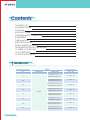
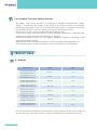
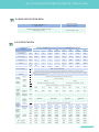
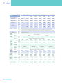
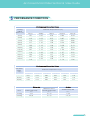
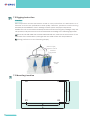
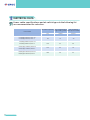
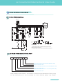
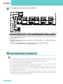
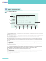
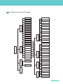
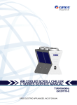
TECHNICAL SALES GUIDE
Capacity Range:60~1216KW
T1/R410A/50Hz/60Hz
C SERIES
Contents
2
3
3
6
9
10
11
14
15
16
18
20
21
1.MODELS LIST
2.NOMENCLATURE
3.FEATURES
4.PRODUCT DATA
5.PERFORMANCE CORRECTION
6.ANTIFREEZE
7.INSTALLATION
8.ELECTRICAL DATA
9.FIELD WIRING DIAGRAM
10.MICROPROCESSOR CONTROLLER
11.WIRED CONTROLLER
12.ACCESSORIES
13.APPLICATION DATA
1 MODELS LIST
Nominal Capacity
TR
Power Supply
Model
Refrigerant
Model Name
Ph, V, Hz
17
LSQWRF65MG/NaC-M
LSQWF65MG/NaC-M
3,380,50
22
LSQWRF80MG/NaC-M
LSQWF80MG/NaC-M
3,380,50
34
LSQWRF130MG/NaC-M
LSQWF130MG/NaC-M
3,380,50
43
LSQWRF160MG/NaC-M
LSQWF160MG/NaC-M
3,380,50
17
LSQWRF65MG/NaC-F
LSQWF65MG/NaC-F
3,220,60
22
LSQWRF80MG/NaC-F
LSQWF80MG/NaC-F
3,220,60
34
LSQWRF130MG/NaC-F
LSQWF130MG/NaC-F
3,220,60
43
LSQWRF160MG/NaC-F
LSQWF160MG/NaC-F
3,220,60
R410A
2 GREE Central Air Conditioners
Air-Cooled Scroll Chiller Technical Sales Guide
2 NOMENCLATURE
QW
F 80
G/Na
C-H
LS LS
QW
R FR80
MM
G/Na
C -F
Model
LS
Water Chiller
QW
Scroll Compressor
R
Heat Pump
F
Air Cooled
80
3
Model
Description
Nominal Cooling Capacity
M
Module
G
Product number
Na
Refrigerant
C
Series number
F
Voltage
Options
Default- Cooling only
R-Heat pump
65=60kW= 17 TR
80=76kW= 22 TR
130=120kW=34 TR
160=152kW=43 TR
Na–R410A
F 208~230V 3N~ 60Hz
M 380~415V 3N~ 50Hz
FEATURES
3.1 Brief Introduction
The units with multi refrigerant circuits from 60 to 152 kW have outstanding benefits that
make this product effective for a variety of applications. The units are shipped from
the factory completely ready for installation and use. Each unit is pressure-tested,
evacuated, and fully charged with R410A, and has an initial oil charge. After
assembly, a complete operation test is performed with water flowing through the
cooler to assure that the refrigeration circuit operates correctly.
The units can be installed on the rooftop, ground outside and so on instead of being
equipped within a special machine room. It can be widely applied in new built or
reconstructed industry and civil-building project, such as hotel, apartment, restaurant,
office building, shopping mall, theater, gymnasium, hospital and so on, as well as
supplies required cooling water for factories in technical process of producing, so it's
especially suitable for some special locations around where there are high-level
requirements for noise and environments and cooling tower are difficult to install.
3
GREE Central Air Conditioners
3.2 Standard Specifications
High Efficiency Full Load Operation
Utilizing new scroll compressor technology, the chillers meet or exceed the
performance requirements of ASHRAE 90.1. All system components are selected for
optimum performance, including the condenser coil areas and evaporator sizes.
Excellent Part Load Performance
By using multi compressors on each chiller, unloading characteristics and part load
performance are outstanding. Integrated part load value (IPLV) is a part load
performance indicator as outlined in ARI Standard 550/590-1998. The IPLV rating
compares the performance of different chillers under identical conditions. When the
IPLV is listed in EER (Energy Efficiency Ratio), a higher EER will indicate that the chiller's
overall performance is better.
Compact Design with Small Footprint
The chillers have a reputation for a compact design and small footprint. A small
footprint can save installation costs by minimizing the size of the concrete mounting
pad or reduces the amount of structural steel if the unit is mounted on the rooftop.
Quiet Operation
The chillers are designed with quiet scroll compressors. Fans are selected for good
performance and lower sound levels. The attention to detail with sound is critical in the
design. Small issues such as refrigerant piping, supports for piping, securing
components to the structure are all important to making a quiet product. We proudly
publish our sound performance.
Superior Controls
GREE has provided the latest technology in controlling the chillers. The new controller
provides a“user friendly”environment for the operator. The control logic is designed
to provide maximum efficiency, to help provide continuing operation in unusual
operating conditions through proactive controls, and to provide a history of conditions
to aid in problem resolutions. Perhaps the greatest benefit is the Protocol for
integrating with your building automation system (BAS).
Compressors
These rugged hermetic compressors are constructed with an integral cast iron frame,
cast iron scrolls, three Teflon impregnated bearings, and three oil filtration devices for
each compressor. One to thity-two compressors can run, depending on the load of
the system, resulting in excellent Part-load efficiency. Each refrigerant circuit has
specially designed oil and gas equalization lines to control oil migration.
The design also offers radial and axial compliance, a large internal volume for liquid
handling, a removable suction screen, and a rotary dirt trap and oil screen. In
addition, the compressor is self-compensating for wear, handles moderate liquid
slugging, and inherently yields high efficiency.
4 GREE Central Air Conditioners
Air-Cooled Scroll Chiller Technical Sales Guide
This well protected compressor includes a solid-state motor protection module, 4
individual motor winding sensors, a patented internal discharge temperature probe,
and a patented shutdown feature that prevents reverse rotation. An internal
discharge check valve helps prevent shutdown noise and comes standard with high
and low pressure taps with Schrader valves, a sight glass, an oil level adjustment valve,
and an off cycle crankcase heater.
Evaporator
The evaporator is direct expansion, shell-and-tube type with water flowing in the
baffled shell side and refrigerant flowing through the tubes. Two independent
refrigerant circuits within the evaporator serve the module's dual refrigerant circuits.
The evaporator has a carbon steel shell and seamless high efficiency copper tubes
roller expanded into a carbon steel tube sheet. Refrigerant heads are carbon steel
with multi-pass baffles to provide oil return . For water removal, 10mm vent and drain
plugs are provided on the top and bottom of the shell. An ambient air thermostat
controls the heater cable. The fitted and glued in place insulation has a K factor of
0.28. The refrigerant side maximum working pressure is 4400 kPa. The water side
working pressure is 1048 kPa. Each evaporator is designed, constructed, inspected,
and stamped according to the requirements of the ASME Boiler and Pressure Vessel
Code.
Condenser
Condenser coils have internally enhanced seamless copper tubes arranged in a
staggered row pattern. The coils are mechanically expanded into flat aluminum
fins with full fin collars. A variety of optional coil material and coatings are
available for corrosive atmospheres.
Fans-The condenser fans are composed of corrosion resistant aluminum hub
and glass-fiber-reinforced polypropylene composite blades molded into a low
noise airfoil section. They are designed for maximum efficiency and are
statically and dynamically balanced for vibration-free operation. They are
directly driven by independent motors, and positioned for vertical air discharge.
The fan guards are constructed of heavy-gauge, rust-resistant, coated steel. All
blades are statically and dynamically balanced for vibration-free operation.
Motors-The fan motors are totally enclosed air-wver, squirrel-cage type. They feature
ball bearings that are double-sealed and permanently lubricated.
3.3 Standard Accessories
Unit on-off switch: ON-OFF switch is provided for manually switching the unit control
circuit.
Indicator lights: LED lights indicate power on to unit, running state and fault indications
due to safety devices.
Filter: Refrigeranting circuits are kept free of sludge, acid and oil contamination with it.
Under voltage and phase protection: Protects against low incoming voltage as well as
single phase, phase reversal.
Liquid line solenoid valve: IT coses when the compressor is off to prevent any liquid
refrigerant from accumulating in the evaporator.
5
GREE Central Air Conditioners
3.4 Standard Control & Safety Devices
The chiller's Unit Control Module is an innovative, modular microprocessor control
design. It coordinates the actions of the chiller in an efficient manner and provides
stand-alone operation of the unit. A Human Interface Panel is a standard component
of the Chiller. Access to all unit controls is via the Human Interface Panel.
Safety valve: Protects the unit against high discharge pressure.
Compressor In-built protection device: Motor winding temperature, discharge gas
temperature and phase reversal for direction of rotation.
Crankcase heaters: Protects the unit against refrigerant migration, oil dilution and
potential compressor failure.
High pressure switch: Provides protection in case of excessive discharge press-ure.
Low pressure switch: Provides protection in case of unsafe low suction pressure.
4 PRODUCT DATA
4.1 Ratings
Model Name
KW/TR
EER
LSQWRF65MG/NaC-M
LSQWF65MG/NaC-M
60 / 17
9.4
LSQWRF80MG/NaC-M
LSQWF80MG/NaC-M
76 / 22
9.4
LSQWRF130MG/NaC-M
LSQWF130MG/NaC-M
120 /34
9.4
LSQWRF160MG/NaC-M
LSQWF160MG/NaC-M
152 / 43
9.4
LSQWRF65MG/NaC-F
LSQWF65MG/NaC-F
60 / 17
9.4
LSQWRF80MG/NaC-F
LSQWF80MG/NaC-F
76 / 22
9.4
LSQWRF130MG/NaC-F
LSQWF130MG/NaC-F
120 /34
9.4
LSQWRF160MG/NaC-F
LSQWF160MG/NaC-F
152 / 43
9.4
EER=Energy Efficiency Ratio at full load-the cooling capacity in Btu's per hour(Btu/h)
divided by the power input in watts, expressed in Btu/h per watts((Btu/h)/watt).
6 GREE Central Air Conditioners
Air-Cooled Scroll Chiller Technical Sales Guide
4.2 UNIT APPLICATION DATA
Voltage Variation
Min./Max.
342/420(50Hz)
198/242(60Hz)
Ambient Air on Condenser coil
Min./Max.℃(℉)
-15/46 ( 41/115)
4.3 SPECIFICATION
LSQWRF_MG/NaC-M
LSQWF_MG/NaC-M
Models
Model
65
80
130
160
65
80
130
160
kW
60
76
120
152
60
76
120
152
kW
21.8
27.6
43.6
55.3
21.8
27.6
43.6
55.3
kW
/
/
/
/
65
80
130
160
Heating input
power
kW
/
/
/
/
21.7
26.7
43.3
53.3
Noise
dB(A)
67
68
69
70
67
68
69
70
Rated cooling
capacity
Input power
for cooling
Rated heating
capacity
Power supply
380~415V 3N~50Hz
Operating control
Microcomputer control, operating status display and abnormal status alarm
High and low voltage switches, freeze prevention switch, over-current protection switch, phase
lacking protector, compressor overheat protection device and software delay starting
compressor protection
Safety protection
devices
Type
CompStarting
ressor
mode
Type
Refrigerant
Control
Totally enclosed flexible scroll compressor
Direct starting
Type
Water
flow
Water
Water
resistance
side
loss
heat
Maximum
excha- bearing
pressure
nger
Diameter
of
water
pipes
Type
Air side
heat
Fan
Motor
exchainput power
nger
Outline
dimension
Package
dimension
R410A
R410A
Electronic expansion valve
Electronic expansion valve
Efficient shell and tube heat exchanger
m³/h
10.3
13.1
20.6
26.1
10.3
13.1
20.6
26.1
kPa
30
35
30
35
30
35
30
35
MPa
mm
1
DN 50
DN 150
DN 50
DN 150
Efficient finned coil tube exchanger
kW
0.7*3
0.7*3
0.7*6
0.7*6
0.7*3
0.7*3
0.7*6
0.7*6
2200
Width
mm
1100
1100
2200
2200
1100
1100
2200
Depth
mm
2265
2265
2265
2265
2265
2265
2265
2265
Height
mm
2214
1180
2214
1180
2214
2280
2214
2280
2214
1180
2214
1180
2214
2280
2214
2280
Width
mm
Depth
mm
2345
2345
2345
2345
2345
2345
2345
2345
Height
mm
2214
900
910
2214
1000
1010
2214
1780
1800
2214
1980
2000
2214
950
960
2214
2214
2214
1050
1060
1880
1900
2080
2100
Net weight
kg
Gross weight
kg
7
GREE Central Air Conditioners
LSQWRF_MG/NaC-F
LSQWF_MG/NaC-F
Models
Model
65
80
130
160
65
80
130
160
kW
60
76
120
152
60
76
120
152
kW
21.8
27.6
43.6
55.3
21.8
27.6
43.6
55.3
kW
/
/
/
/
65
80
130
160
Heating input
power
kW
/
/
/
/
21.7
26.7
43.3
53.3
Noise
dB(A)
67
68
69
70
67
68
69
70
Rated cooling
capacity
Input power
for cooling
Rated heating
capacity
Power supply
208~230V 3N~60Hz
Operating control
Microcomputer control, operating status display and abnormal status alarm
High and low voltage switches, freeze prevention switch, over-current protection switch, phase
lacking protector, compressor overheat protection device and software delay starting
compressor protection
Safety protection
devices
Type
CompStarting
ressor
mode
Type
Refrigerant
Control
Totally enclosed flexible scroll compressor
Direct starting
Type
Water
flow
Water
Water
resistance
side
loss
heat
Maximum
excha- bearing
pressure
nger
Diameter
of
water
pipes
Type
Air side
heat
Fan
Motor
exchainput power
nger
Outline
dimension
Package
dimension
R410A
R410A
Electronic expansion valve
Electronic expansion valve
Efficient shell and tube heat exchanger
m³/h
10.3
13.1
20.6
26.1
10.3
13.1
20.6
26.1
kPa
30
35
30
35
30
35
30
35
MPa
mm
1
DN 50
DN 150
DN 150
Efficient finned coil tube exchanger
kW
0.7*3
0.7*3
0.7*6
0.7*6
0.7*3
0.7*3
0.7*6
0.7*6
2200
Width
mm
1100
1100
2200
2200
1100
1100
2200
Depth
mm
2265
2265
2265
2265
2265
2265
2265
2265
Height
mm
2214
1180
2214
1180
2214
2280
2214
2280
2214
1180
2214
1180
2214
2280
2214
2280
Width
mm
Depth
mm
2345
2345
2345
2345
2345
2345
2345
2345
Height
mm
2214
900
910
2214
1000
1010
2214
1780
1800
2214
1980
2000
2214
950
960
2214
2214
2214
1050
1060
1880
1900
2080
2100
Net weight
kg
Gross weight
kg
The operation weight of the unit is equal to 110% of its net neight.
8 GREE Central Air Conditioners
DN 50
Air-Cooled Scroll Chiller Technical Sales Guide
5
PERFORMANCE CORRECTION
Performance Correction Value
Leaving
Chilled
Water ℃(℉)
Ambient Temperature ℃(℉)
25(77)
30(86)
35(95)
5(41.0)
1.07
1.00
0.94
0.84
0.81
6(42.8)
1.10
1.03
0.97
0.87
0.83
7(44.6)
1.14
1.07
1.00
0.91
0.86
8(46.4)
1.17
1.10
1.03
0.94
0.88
9(48.2)
1.20
1.13
1.06
0.98
0.91
10(50.0)
1.23
1.16
1.09
1.01
0.93
11(51.8)
1.27
1.19
1.12
1.04
0.96
12(53.6)
1.31
1.23
1.15
1.07
0.99
13(55.4)
1.34
1.26
1.17
1.09
1.01
14(57.2)
1.37
1.29
1.20
1.12
1.03
15(59.0)
1.41
1.32
1.23
1.14
1.06
40(104)
45(113)
Performance Correction Value
Hot Water
Outlet
℃(℉)
Ambient Temperature ℃(℉)
-10(14)
-5(23)
0(32)
5(41)
10(50)
15(59)
40(104)
0.67
0.75
0.85
0.95
1.06
1.18
45(113)
0.66
0.74
0.84
0.95
1.05
1.18
50(122)
0.64
0.74
0.84
0.94
1.05
1.17
Water side
Air side
Difference of the
in/outlet water temp.
(℃)
2.5 ~ 8
Ambient temp. Db
(℃)
Cooling
Outlet water temp.
(℃)
5 ~15
Heating
40 ~ 50
2.5 ~ 8
-15 ~ 24
Item
5 ~ 46
9
GREE Central Air Conditioners
6
ANTIFREEZE
Ethylene Glycol Factors
The units can operate with a leaving chilled fluid temperature from of20℉ to 60℉(-6℃
~16℃) A glycol solution is required when leaving chilled fluid temperature is below4.5
℃.The use of glycol will reduce the performance of the unit depending on
concentration.
% by Weight
10
20
30
40
50
Freezing Point ℃ ( ℉ )
-3.3(26)
-7.8(18)
-13.9(7)
-21.7(-7) -33.3(-29)
Ambient Temperature ℃ ( ℉ )
-16.7(2) -26.7(-16)
8.3(47)
-1.7(29)
-6.7(20)
Cooling Capacity Correction Factor
0.998
0.993
0.987
0.980
0.973
Water flow Correction Factor
1.036
1.060
1.092
1.132
1.182
1.07
1.10
1.18
1.24
1.30
Pressure Drop Correction Factor
NOTE: Ethylene and propylene glycol ratio is the scope of Standard ARI 550/590-98
certification program.
10 GREE Central Air Conditioners
℃
Air-Cooled Scroll Chiller Technical Sales Guide
INSTALLATION
7.1 Dimensions
a、Graph for the shape and dimensions for
LSQWRF65MG/NaC-M,LSQWF65MG/NaC-M,LSQWRF80MG/NaC-M,
LSQWF80MG/NaC-M,
LSQWRF65MG/NaC-F, LSQWF65MG/NaC-F ,LSQWRF80MG/NaC-F, LSQWF80MG/NaC-F 。
,
2155
2214
Rubber cushion aren t show in this view.
b、Graph for the shape and dimensions for
LSQWRF130MG/NaC-M,LSQWF130MG/NaC-M ,
LSQWRF160MG/NaC-M,LSQWF160MG/NaC-M,
LSQWRF130MG/Na-F , LSQWF130MG/NaC-F , LSQWRF160MG/NaC-F,LSQWF160MG/NaC-F.
,
Rubber cushion aren t show in this view.
680
2214
2155
7
11
GREE Central Air Conditioners
7.2 Rigging Instruction
Caution
Strict inspection and test have been made to every unit before it is delivered out of
factories to ensure the performance and quality. Therefore, please be careful d u r i n g
assembly and mobilization. Don’t damage control system and pipe components.
Mobilize the unit to the nearest assembly location before removing the package. Keep the
unit upward, carry the removed unit and assemble according to the following approach:
a. Move the unit with roller rod: Put three roller rods with the same size at the bottom of the
unit. Each of the rods shall be 1/5 longer than the width of the unit. Keep balance.
b. Lifting (reference to the following Graph).
Guard bars are slightly
longer than size of the unit
Soft Material
Protection Block
Hoisting Hole
Position
7.3 Mounting Location
R3
R1
R2
D
C
R4
B
A
12 GREE Central Air Conditioners
Air-Cooled Scroll Chiller Technical Sales Guide
7.3 Mounting Location
Model
LSQWRF65MG/NaC-M
LSQWF65MG/NaC-M
LSQWRF80MG/NaC-M
LSQWF80MG/NaC-M
LSQWRF130MG/NaC-M
LSQWF130MG/NaC-M
LSQWRF160MG/NaC-M
LSQWF160MG/NaC-M
LSQWRF65MG/NaC-F
LSQWF65MG/NaC-F
LSQWRF80MG/NaC-F
LSQWF80MG/NaC-F
LSQWRF130MG/NaC-F
LSQWF130MG/NaC-F
LSQWRF160MG/NaC-F
LSQWF160MG/NaC-F
A
B
C
D
2265
1650
1100
1028
2265
1650
1100
1028
2265
1650
2200
2128
2265
1650
2200
2128
2265
1650
1100
1028
2265
1650
1100
1028
2265
1650
2200
2128
2265
1650
2200
2128
7.4 Installation Interspace
Room for unit assembly shall be open with free ventilation and without short circuit of air flow.
Specific assembly sizes are shown in the graph with unit of mm.
13
GREE Central Air Conditioners
8 ELECTRICAL DATA
Power cable specifications and air switch types in the following list
are recommended for selection.
Air switch capacity
Unit Model
14 GREE Central Air Conditioners
Min. sectional
Min. sectional area
of grounding cable area ofpower cable
(A)
(mm² )
(mm² )
LSQW(R)F65MG/NaC-M
LSQW(R)F65MG/NaC-F
63
16
25
LSQW(R)F80MG/NaC-M
LSQW(R)F80MG/NaC-F
100
25
50
LSQW(R)F130MG/NaC-M
LSQW(R)F130MG/NaC-F
125
35
70
LSQW(R)F160MG/NaC-M
LSQW(R)F160MG/NaC-F
180
50
95
Air-Cooled Scroll Chiller Technical Sales Guide
9 FIELD WIRING DIAGRAM
L1
L2
L3
N
9.1 FIELD WIRING DIAGRAM
Q
HL1
Q9
Q11
A2
XT3-11
QN
A2
XT3-15
A2
XT3-13
M1
EH2
EH1
Q1
KM9
KM8
KM7
XT3-14
A1
A1
B1
C1
N
XT3-12
A1
电压表
XT3-16
A1
Assistant Heater
Q12
Q-Q11 3
KM9
KM7
KM8
KM7-KM9
Q12
HL1-4
Specification:
HL2
HL4
1、Auxiliary electric heater is optional part for heat pump unit.The
diagram connected shown above.
2、Cooling only type unit do not have AssistantHeater,KM7,KM8,HL4.
9.2 WIRING FOR EXTERNAL CONTROL USERS
Connection for External Control User
Output Control User Pump Contactor (220V live wire)
Output Control Zero Line
Output Control Electric Heater 2 Contactor(220V live wire)
Output Control Zero Line
Output Control Electric Heater 1 Contactor (220V live wire)
Output Control Zero Line
marks: Auxiliary electric heater 1 and 2 and AC contactor output control line of user’s pump
can be connected to 11,12,13,14,15and 16 of the terminal (XT3)of any module.
15
GREE Central Air Conditioners
COM1
CN2
9.3. The Modules are connected as follow:
wired
controller
CN1
130/160
Communication
Module
CN25
COM2 COM2
CN25
Main Board CN15
PC
CN33
Main Board CN15
PC
CN33
Left Electric Box
Right Electric Box
80 Electric Box
130/160 Electric Box
Electric Box
CN25
Main Board
CN15
PC
CN33
Left Electric Box
CN25
Main Board CN15
PC
CN33
Right Electric Box
CN25
CN25
Main Board CN15
PC
Main Board CN15
PC
CN33
XT1
XT2
XT1
XT2
XT1
L1 L2 L3 N
8 9 10
L1 L2 L3 N
8 9 10
L1 L2 L3 N
65 Electric Box
CN33
XT2
8 9 10
XT1
L1 L2 L3 N
XT2
8 9 10
power
380V 3N~ 50Hz
Buiding control
system
Connect With
Water Flow Swith
380V 3N~ 50Hz
380V 3N~ 50Hz
380V 3N~ 50Hz
to next unit
——until the
last one
B RS232/485
A Convertor
Long-distance
Minitor PC
2.Use a 3-core(2×1mm )signal wires to connect the Water Flow Switch with the terminal 8,9 in one of the units.
3. Use a 4-core(4×25mm ~95 mm ) wires to connect each module terminal XT1 L1,L2,L3,N together.Referrence
with the diagram shown above.
4.130/160means:
LSQW(R)F130MG/NaC-M、LSQW(R)F160MG/NaC-M、LSQW(R)F130MG/NaC-F、LSQW(R)F160MG/NaC-F;
(two modules in each one)
80 means:LSQW(R)F80MG/NaC-M、LSQW(R)F80MG/NaC-F; ( one module in each one)
65 means:LSQW(R)F65MG/NaC-M、LSQW(R)F65MG/NaC-F. ( one module in each one)
10 MICROPROCESSOR CONTROLLER
1.
Automatic control of compressor start/stop, condenser fans, evaporator pump,
evaporator heater, unit alarm contacts, and chiller operation from 5℉ to 115℉(-15℃ to 46
℃)ambient. Automatic reset to normal chiller operation after power failure.
2. Software stored in non-volatile memory.
3. Liquid Crystal Display, descriptions in English, numeric data in Metric unit. Sealed keypad
with sections for On/Off Switch, Reset, Up, Down, Exit and Entry.
4. Programmable set-points (within Manufacturer limits):chilled liquid temperature set-point
and range, evaporate heater on/off temperature set-point and range, daily
schedule/holiday for start/stop.
5. Display Data: Return and leaving liquid temperatures, outdoor air temperature,
discharge temperature, suction temperature, compressor run status, fan run status, day, date
and time, compressor starts/operating hours.
16 GREE Central Air Conditioners
Air-Cooled Scroll Chiller Technical Sales Guide
6. System Safeties: Shall cause individual compressor systems to perform auto shut down.
Manual reset required after the third trip of low pressure switch in 60 minutes. Manual reset
required after every trip. Includes: high discharge temperature, high pressure switch.
Compressor motor protector shall protect against damage due to high input current or
thermal overload of windings.
7. Unit Safeties: Shall be automatic reset and cause compressors to shut down if low leaving
chilled liquid temperature, and flow switch operation. Contractor shall provide flow switch
and wiring per chiller manufacturer requirements.
8. Alarm Contacts: low leaving chilled liquid temperature, high discharge temperature, high
pressure, low pressure.
17
GREE Central Air Conditioners
11
WIRED CONTROLLER
11.1 Operation View
1
Power
XXXX-XX-XX XX:XX
C Series Chiller
2
Cool【Heat/Defrost】
Run
On【Off】
10
【Manual/Timer】 XModules【 【
3
Error
On/off
Reset
4
5
1.Power indicator(red):
6
7
Exit
Confirm
8
9
the indicator is on when the wired controller is powered on, or otherwise
it is off.
2.Run indicator(green): the indicator is on when the wired controller is started, or otherwise it is off.
3.Error indicator(red): The indicator is on when the unit is at fault, or otherwise it is off.
4.On/Off button: For controlling unit conversion between start and stop, press the button (for 3
seconds)in stop state to start the unit and press the button (for 3 seconds) in operation state to stop
the unit.
5.Reset button: Press the button to clear fault and relieve the air discharge temperature sensor
locking.
6.Up selection button: in menu selection, press the button to move the cursor upward or leftward;
and indata modification mode, press the button to increase the value.
7.Down selection button: In menu selection, press the button to move the cursor downward or
rightward; and in data modification mode, press the button to decrease the value.
8.Exit button: Press the button to go back to the previous menu.
9.Confirm button: In menu selection, press the button to confirm the selected item; and in data
modification mode, press the button to confirm the parameter and move the cursor.
10.LCD: Information display zone.
18 GREE Central Air Conditioners
Air-Cooled Scroll Chiller Technical Sales Guide
11.2 Menu Structure of Controller
Menu Structure
R
Run Mode
C Water Tin XX.X℃
C Water Tout XX .X℃
Startup
H Water Tin XX.X℃
Auxiliary Heat
H Water Tout XX .X℃
Auto-Antifreeze
Defrost T1 XX.X℃
User’ s Setup
User
’s
Setu
p
Timer Setup
Defrost T2 XX.X℃
Clock Setup
Anti-Heat T XX.X℃
Ambient T XX .X℃
Sound
Suction T1 XX.X℃
Backlight
Suction T2 XX.X℃
ECO. Model
Exhaust T1 XX.X℃
Memory Start
Temp. View
Quiet Model
Exhaust T2 XX.X℃
Throttle T1 XX.X℃
Throttle T2 XX.X℃
Module 1
Module 2
Fan 1
Main Menu
Module View
Module 3
Fan 2
:
Fan 3
Sys.State
:
Compressor 1
:
Compressor 2
Module 15
State View
:
C Water Pump
H Water Pump
Ass.Heat 1
Module 16
Ass.Heat 2
4-Valve 1
4-Valve 2
SystemPara.Setup
Error View
Parameter Setup
User Para.Setup
EXV.1
EXV.2
Exthalpy Inc .EXV.1
Version
Exthalpy Inc .EXV.2
Dis. T Sensor 1
Manal Defr ost
Dis. T Sensor 2
Water_Out EXV .
Water_In EXV .
19
GREE Central Air Conditioners
12
ACCESSORIES
S=Standard
O=Optional
F=Field supply
Model
20 GREE Central Air Conditioners
Accessories Name
Cooling only
Heat pump
1
Module unit
S
S
2
wired controller (necessary)
O
O
3
Four-core control connection cord
(3 meters)
S
S
4
Three-core signal cable (3 meters)
F
F
5
Water flow switch
S
S
6
Electric control box
F
F
7
Auxiliary electric heater
----
O
8
Power connection wire
F
F
9
Control connection cord
F
F
10
Flexible joint
F
F
11
Thermometer
F
F
12
Pressure gauge
F
F
13
Water tank
F
F
Air-Cooled Scroll Chiller Technical Sales Guide
13 APPLICATION DATA
Unit Location
The chillers are designed for outdoor installation. When selecting a site for installation,
be guided by the following conditions:
1. For outdoor locations of the unit, select a place having an adequate supply of fresh
air for the condenser.
2. Avoid locations beneath windows or between structures where normal operating
sounds may be objectionable.
3. Installation sites may be either on a roof, or on the ground.
4. The condenser fans are the propeller-type, and are not recommended for use with
duct work in the condenser air stream.
5. When it is desirable to surround the unit(s), it is recommended that the screening be
able to pass the required chiller CFM without exceeding 0.1" of water external static
pressure.
6.Recommended clearances for units are given in DIMENSIONS. When the available
space is less, the unit(s) must be equipped with the discharge pressure transducer
option to permit high pressure unloading in the event that air recirculation were to
occur.
Foundation
The unit should be mounted on a flat and level foundation, ground or roof, capable of
suppo-rting the entire operating weight of the unit.. Operating weights are given in the
Dimensions.
For ground level installations, precautions should be taken to protect the unit from
being tamp-ered by or injuring to unauthorized persons. Screws on access panels will
prevent casual tam-pering; however, further safety precautions, such as unit enclosure
options, a fencedin enclos-ure, or locking devices on the panels may be advisable.
Check local authorities for safety regu-lations.
Chilled Liquid Piping
The chilled liquid piping system should be laid out so that the circulating pump dis ch
arges into the cooler. The inlet and outlet cooler liquid connections are given in
Dimensions.
Delivery and Handling
A. Unit shall be delivered to job site fully assembled, and charged with refrigerant and
oil by the Manufacturer.
B. Unit shall be stored and handled according to the Manufacturer’s instructions.
Leveling Unit
Unit must be leveled when installed to ensure proper oil return to the compressors.
Fluid Temperature
Maximum leaving chilled fluid temperature for unit is 59 ℉ (15℃ ). For conti-nuous
operation, it is recommended that inlet fluid temperature does not exceed 86 ℉(30℃)
( If continuous ope-ration is required for inlet water temperature above 86℉ (30℃ ),
please refer to GREE factory).
Minimum leaving chilled fluid temperature for standard unit is 38 ℉ (3.3℃ ) (For lower
leaving temperature contact GREE factory).
21
GREE Central Air Conditioners
Cooler Flow Range:
Chiller ratings and performance data pertain to cooling temperature rise of 10 ℉ (12.4℃ ). Chillers maybe suitable for operation in a range from 5.4 to 14.5 ℉ (-15~-9.9
℃ )temperature rise without adjustment, provided flow limits are not exceeded. High
flow rate is limited by pressure drop that can be tolerated ( for any high flow rate value
larger than values in performance tables, please refer to GREE factory).
Minimum Cooler Flow: Minimum cooler flow will be based on the maximum permissible AT
across the cooler 14.5℉(-9.9℃).
Maximum Cooler Flow
It Will be based on Minimum permissible AT across the cooler 5.4℉(-15℃).
Cooler protection
A protection against low ambient freeze-up is required for ambient temperatures below
32℉ (0℃ ) . Protection should be in the form of: Inhibited ethylene glycol or any other
suitable glycol .
Condenser Airflow
Any restrictions on units fan airflow will affect unit capacity, condenser head pres-sure, and
compressor power input. Such restrictions (i.e. not providing vertical clear-ance or lateral
clearance, insufficient unit-to-unit clearance ) will cause warm air rec-irclation or coil
starvation. Minimum required operational and maintenance clearan-ces around the unit
are shown in the figure below.
22 GREE Central Air Conditioners