1
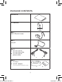
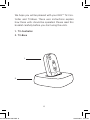
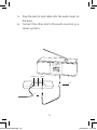
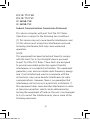
9 514 0130 041 #01.indd 1 User instructions TV-Dex 20-04-2011 15:27:30 Package Contents User manual TV-Controller Box 1: Mini USB power supply Box 2: Lanyard Box 3: a. 3.5 mm jack to 3.5 mm jack cable b. 3.5 mm jack to phono cable a. b. Box 4: a.TV-Base b. SCART adaptor (For European markets only) 9 514 0130 041 #01.indd 2 a. b. 2 20-04-2011 15:27:31 Contents Package Contents . . . . . . . . . . . . . . . . . . . . . . . . . . . . . . . . . . . 2 Your new TV-DEX . . . . . . . . . . . . . . . . . . . . . . . . . . . . . . . . . . . . 5 TV-Controller . . . . . . . . . . . . . . . . . . . . . . . . . . . . . . . . . . . . . . 7 TV-Base . . . . . . . . . . . . . . . . . . . . . . . . . . . . . . . . . . . . . . . . . . . . . . 8 Light-emitting diodes . . . . . . . . . . . . . . . . . . . . . . . . . . . . . . . 9 Getting started . . . . . . . . . . . . . . . . . . . . . . . . . . . . . . . . . . . . 10 Connecting the units: . . . . . . . . . . . . . . . . . . . . . . . . . . . . 10 When using more than one tv-base . . . . . . . . . . . . . . . 15 Usage . . . . . . . . . . . . . . . . . . . . . . . . . . . . . . . . . . . . . . . . . . . . . . 16 INSTRUCTIONS FOR LANYARD USAGE . . . . . . . . . . . . . . . . . . 18 Transmission . . . . . . . . . . . . . . . . . . . . . . . . . . . . . . . . . . . . . . 19 Adjusting the volume . . . . . . . . . . . . . . . . . . . . . . . . . . . . . 21 Mute . . . . . . . . . . . . . . . . . . . . . . . . . . . . . . . . . . . . . . . . . . . . . . . 21 Room off . . . . . . . . . . . . . . . . . . . . . . . . . . . . . . . . . . . . . . . . . . 21 Recharging the battery . . . . . . . . . . . . . . . . . . . . . . . . . . 22 Troubleshooting . . . . . . . . . . . . . . . . . . . . . . . . . . . . . . . . . . . 23 Safety Warning . . . . . . . . . . . . . . . . . . . . . . . . . . . . . . . . . . . . 27 Regulatory Information . . . . . . . . . . . . . . . . . . . . . . . . . . 28 9 514 0130 041 #01.indd 3 3 20-04-2011 15:27:31 symbols The following symbols will be used throughout the manual: WARNING Messages with this heading indicate adverse reactions, potential safety hazards or inadequate device performance. CAUTION Messages with this heading indicate/include information regarding any special care to be exercised. 9 514 0130 041 #01.indd 4 Non-ionizing radiation. Not for general waste. 4 20-04-2011 15:27:31 Your new TV-DEX Your TV-DEX is part of the DEX™ family of assistive listening devices. These user instructions explain how the TV-DEX should be operated. WARNING This booklet contains important information and instructions. Please read this booklet carefully before you start using the device. Intended use The TV-DEX is a wireless device intended for listening directly to the TV or other audio sources. Description of device The TV-DEX allows the user to listen to audio input using WidexLink for connection to Widex hearing aids. 9 514 0130 041 #01.indd 5 5 20-04-2011 15:27:31 We hope you will be pleased with your DEX™ TV-Controller and TV-Base. These user instructions explain how these units should be operated. Please read this booklet carefully before you start using the units. 1.TV-Controller 2.TV-Base 1. 2. 9 514 0130 041 #01.indd 6 6 20-04-2011 15:27:31 TV-Controller The controller is provided with four keys: 1. Transmission on/off 2.Room off 3. Volume up 4.Volume down 9 514 0130 041 #01.indd 7 1. 3. 4. 2. 7 20-04-2011 15:27:32 TV-Base On the back of the base you will find the following inputs: 1.Power 2.TV 3.Audio 1. 2. 3. On the underside of the base there is a switch with a choice of two settings: 1.HEARING AID 2.HEARING AIDS 1. 1. Monaural/binaural switch The setting chosen by your hearing care professional depends on whether you use a hearing aid in only one ear (monaural) or in both ears (binaural). 9 514 0130 041 #01.indd 8 8 20-04-2011 15:27:32 Light-emitting diodes There are two light-emitting diodes (LEDs) on the controller. 1. Constant green light: Transmission 2. Changing from green to red: Transmission off 3. Constant red light: Room off active 4.Flashing red and green light: Battery charging 9 514 0130 041 #01.indd 9 2. 1. 4. 3. 9 20-04-2011 15:27:32 Getting started You can skip steps 5+6 if you only wish to transmit from the TV, and steps 3+4 if you only wish to transmit from an audio source. Connecting the units: 1. Connect the mini-USB power supply unit to the base. (The supply unit is available in four versions. Your supply may therefore not look exactly as illustrated). 2. Plug the other end into a wall outlet. POWER TV AUDIO 1. 2. 9 514 0130 041 #01.indd 10 10 20-04-2011 15:27:32 3a. Connect the jack to phono cable to the base. 4a. Plug the two phono connectors at the other end of the cable into AUDIO OUT on the TV. Please refer to the user guide for your TV for further details. POWER TV AUDIO 3a. 4a. 9 514 0130 041 #01.indd 11 11 20-04-2011 15:27:33 For European markets only: If the TV has no AUDIO OUT, a SCART adaptor should be used: 3b. Connect the phono connectors to the two terminals on the included SCART adaptor (red to red and white to white). 4b. Plug the SCART adaptor into the TV´s SCART socket. 4b. 3b. 9 514 0130 041 #01.indd 12 12 20-04-2011 15:27:33 5. Plug the jack to jack cable into the audio input on the base. 6. Connect the other end to the audio source (e.g. a stereo system). 9 514 0130 041 #01.indd 13 POWER TV AUDIO 6. 5. 13 20-04-2011 15:27:33 7. Place the controller in the base and allow it to charge for eight hours (the first time). 9 514 0130 041 #01.indd 14 14 20-04-2011 15:27:34 When using more than one tv-base If you only have one base, this base is automatically selected the first time you charge the controller in the base. If you have more than one base, you can change between these by placing the controller in the base you wish to use for approx. 5 seconds. 9 514 0130 041 #01.indd 15 15 20-04-2011 15:27:34 Usage 9 514 0130 041 #01.indd 16 Up to 3 ft/1 m When appropriate, the TV controller may be attached to the lanyard in your package contents to wear around the neck as a convenience. Up to 30 ft / 10 m 16 20-04-2011 15:27:34 Caution for pacemaker users (Risks) The use of the CLEAR/DEX should not interfere with other devices such as a pacemaker. However, to be extra cautious, Widex follows the guidelines recommended by the manufacturers of implantable defibrillators and pacemakers for their patients when using mobile phones. Specifically, hearing aid wearers who also use a pacemaker should •Keep the hearing aids at a distance of at least 15 cm/½ foot away from the pacemaker and •Do not carry the hearing aids (and/or any of the DEX accessories) in a shirt pocket or close to the chest. •If any interference is observed, do not use the hearing aids (and/or DEX) and contact your pacemaker manufacturer and hearing healthcare professional immediately. 9 514 0130 041 #01.indd 17 17 20-04-2011 15:27:34 INSTRUCTIONS FOR LANYARD USAGE Place the controller in the plastic holder at the end of the lanyard as illustrated. WARNING The breakaway buckle of the lanyard must be positioned at the back of your neck (1). 9 514 0130 041 #01.indd 18 18 20-04-2011 15:27:35 Transmission With either TV or audio connected • Press the transmission on/off key on the controller once to start transmitting from the connected source. An acoustic signal will sound in your hearing aids, and the transmission LED will turn green. • Press the key again once to stop transmission. The hearing aids will enter the Master program as indicated by a voice message or beep tones. The green LED will change briefly to red and then off. With both TV and audio connected: • Press the transmission on/off key on the controller once to start transmission from the TV. An acoustic signal will sound in your hearing aids, and the transmission LED will turn green. • Press the key a second time to transmit sound from the audio source instead. An acoustic signal will sound in your hearing aids. • Press the key a third time to stop transmission. The hearing aids will enter the Master program, as indicated by a voice message or beep tones. The green LED will change briefly to red and then off. 9 514 0130 041 #01.indd 19 19 20-04-2011 15:27:35 If you carry your controller around with you and move outside the operating range, transmission will be interrupted and your hearing aids will switch to the Master program. The LED will flash at slow intervals to indicate that transmission has been interrupted. The change will be indicated by a voice message. If your hearing aids are set up with beep-tone indication instead, no acoustic indication will sound. If you come in range again, the controller will detect the signal from the TV/Audio and restart transmission. A sound will be heard in the hearing aids. The LED will light constantly rather than flash. Note that the LED may continue to be red if you chose to turn off the hearing aid microphones during transmission. 9 514 0130 041 #01.indd 20 20 20-04-2011 15:27:35 Adjusting the volume Press the volume up key to raise the volume of the transmitted TV or audio sound. Press the volume down key to lower the volume. UP DOWN Mute You can mute the transmitted TV or audio sound on the TV or audio source. Room off If you wish to turn the hearing aid microphones off during transmission, so that you only hear the transmitted sound, press the room on/off key once. To turn the microphones back on, press again. An acoustic indicator will sound in your hearing aids, and the red LED will turn off. 9 514 0130 041 #01.indd 21 21 20-04-2011 15:27:35 Recharging the battery The controller uses a rechargeable battery. When fully charged, the battery has a capacity of approx. 10 hours of transmission, decreasing over time. When the battery runs low, transmission is interrupted. To recharge the battery, place the controller in the base for approximately 4 hours. You can also recharge the battery using an appropriate USB power supply supplied by Widex. Contact your hearing care professional if the battery needs replacement. WARNING Do not attempt to change the battery yourself. Contact your hearing care professional if the battery needs replacement. 9 514 0130 041 #01.indd 22 22 20-04-2011 15:27:36 Troubleshooting Problem Potential cause Solution Your TV-Controller does not work The battery is exhausted Charge the battery Base has not been selected Place the TV-Controller in the TV-Base for at least 5 seconds The battery needs replacement Contact your hearing care professional The jack plug for tv or audio connection is not connected to the TVBase Connect the jack plug as shown on page 11,13 The TV-Base is not connected to the electrical power source Connect the TV-Base as described on page 10 The green diode on the TV-Controller turns on for a brief period of time and then turns off No transmitted TV/audio source is not sound even if switched on the green diode Sound source and TVis turned on Base are not properly connected Switch TV/audio source on Transmission in- TV-Controller battery is terrupted exhausted Charge the TV-Controller TV-Controller is out of operating range When transmitting, parts of the sound image from the TV/audio source are missing 9 514 0130 041 #01.indd 23 Connect the sound source and TV-Base as shown on pages 11,12,13 Move within operating range Monaural/binaural switch Check that the switch is on the underside of the in the correct position. TV-Base is not set corSee page 8. rectly 23 20-04-2011 15:27:36 Problem Potential cause Solution Temporary suspension of communication between hearing aids. Message: “Partner check” Interference from devices Keep at least 15 cm./ emitting a strong electro- ½ foot away from potenmagnetic field. tial sources of interference. Volume of TV-Base is not connected transmitted to the correct output sound changes when you adjust the volume of the sound source 9 514 0130 041 #01.indd 24 Connect the TV-Base to the correct TV/audio output. Please refer to the user instructions for the TV/audio source. 24 20-04-2011 15:27:36 CARING FOR YOUR TV-DEX The device is a valuable object and should be treated with care. Here are some things you can do to prolong the life of your TV-DEX: WARNING •Do not expose the device to extreme temperatures or high humidity. •Do not immerse in water or other liquids. •Do not carry your TV-DEX with you during X-rays, MRIs or other scans or radiation treatments and never place it in a microwave oven. These are some of the types of radiation that can damage the device. CAUTION •Never try to open or repair the device yourself. (This should only be done by authorized personnel.) •Clean the device with a soft cloth. Never wash it with water, cleaning solutions or other liquids. •Avoid dropping the TV-DEX. •When the device is not in use, keep it in its case in a cool, dry location out of reach of children and pets. 9 514 0130 041 #01.indd 25 25 20-04-2011 15:27:36 Warnings WARNING •Keep the TV-DEX and its parts and accessories out of reach of children and anyone else who might swallow parts of the device, or otherwise cause injury to themselves with these items. In case of ingestion, contact a physician immediately. •Do not use the device on aircraft or in hospitals without permission. •Do not use the device in mines or other areas with explosive gases. •If you wear your TV-DEX around your neck, make sure that the breakaway buckle on the lanyard is always at the back of your neck. CAUTION •Although the device has been designed to comply with the most stringent international electromagnetic compatibility standards, the possibility cannot be excluded that it may cause interference with other equipment, such as medical devices. 9 514 0130 041 #01.indd 26 26 20-04-2011 15:27:36 Safety Warning This device is powered by an external power supply. • Only connect a power supply that is compatible with the TV-DEX. • The power supply must have an output rating of 5VDC, 500mA, and a mini USB connector. • The power supply input rating voltage and wall plug must be compatible with the AC wall outlet in your region. • The power supply must have the certification marks showing certification by a safety agency acceptable in your region. Widex strongly recommends that you always use a power supply unit that is supplied by your Widex Distributor to ensure safe and efficient use of your TV-DEX. 9 514 0130 041 #01.indd 27 27 20-04-2011 15:27:36 Regulatory Information The following Table summarizes the technical details of the WidexLink technology as it is implemented in the CLEAR hearing aids. Unit TV-Controller TV-Base Hearing aid C4‑PA Type Radio 2 Radio 1 Radio 1 Radio 2 Antenna type Inductive antenna Planar Inverted F antenna PCB F antenna Inductive antenna NA NA Ø1.8 mm L – 4.85mm Antenna Ø6 mm dimensions L – 40mm Modulation FSK GFSK GFSK FSK Magnetic Field Strength -9dBµA/m at 10m distance NA NA -54dBμA/m at 10m distance Output power 11nW EIRP* +4 dBm EIRP* +4 dBm EIRP* 29pW EIRP* Range <1m remote <10m unit to between tv hearing aid. and TV‑DEX. <10m between tv and TV‑DEX. <1m remote unit to hearing aid. <30cm between hearing aids Center frequency 10.6MHz 2.45GHz ISM 2.45GHz ISM 10.6MHz Channels Single channel radio 17 logical channels 17 logical channels Single channel radio Bandwidth 660kHz (-15dB) 2 MHz 2 MHz 660kHz (-15dB) Data rate 2 Mbit/s 2 Mbit/s 212kbit/s raw channel capacity 9 514 0130 041 #01.indd 28 212kbit/s raw channel capacity 28 20-04-2011 15:27:36 Data flow Simplex Time division duplex (TDD) Time division duplex (TDD) Simplex or semiduplex Protocol Random access – no collision avoidance. Packet based protocol, time divided. Packet based protocol, time divided. Random access – no collision avoidance. * EIRP = Equivalent isotropically radiated power. (Benefits) The use of wireless transmission allows convenient and synchronized control of hearing aid functions. The CLEAR wireless hearing aids share input information between the two partner hearing aids. In so doing, the wearers would experience the following additional user benefits (only when wearing binaural CLEAR hearing aids). Synchronization of volume control setting between hearing aids – The volume in both hearing aids will change when the VC is adjusted on one ear. Synchronization of listening programs between hearing aids – The same listening program is used in both hearing aids when one is changed by the user. Surveillance of partner hearing aid – The hearing aid(s) will signal an alert (“partner check”) when a hearing aid battery has expired, or that one of the hearing aids has fallen off. In rare instances, a much stronger wireless source nearby may activate this alert. This serves as an early warning to the wearer of such service interruption. 9 514 0130 041 #01.indd 29 29 20-04-2011 15:27:36 Coordination of compression – The CLEAR hearing aids maintain the intensity level difference between ears (inter-aural level difference, ILD). In some situations where speech is presented to one side and noise the other side, this coordinated action could enhance the relative loudness of the speech sounds to the noise background and improve speech understanding for some wearers. More accurate identification of feedback – The CLEAR hearing aids distinguish between “true” hearing aid whistling (or feedback) and music sounds to prevent unnecessary feedback cancellation and preserve natural sound quality. (Contraindications): •Congenital or traumatic deformity of the ear •Active drainage from the ear within 90 days •History of rapid progressive hearing loss within previous 90 days •Acute or chronic dizziness •Sudden unilateral hearing loss in previous 90 days The TV-DEX contains radio transmitters / receivers with the following TV-BASE radio transmitter parameters: •Frequency (range): 2.45 GHz (2.4 – 2.5 GHz) •Bandwidth: 2 MHz •Channel: 17 logical channels •Modulation: GFSK •Radiated output power: 2.5 mW / +4 dBm •Magnetic field strength: N/A •Duty Cycle: 100 % (averaged over 1 hour of operation) •Time division duplex (TDD) 9 514 0130 041 #01.indd 30 30 20-04-2011 15:27:36 TV-CONTROLLER radio 1 transmitter parameters: •Frequency (range): 2.45 GHz (2.4 – 2.5 GHz) •Bandwidth: 2 MHz •Channel: 17 logical channels •Modulation: GFSK •Radiated output power: 2.5 mW / +4 dBm •Magnetic field strength: N/A •Duty Cycle: 100 % (averaged over 1 hour of operation) •Time division duplex (TDD) TV-CONTROLLER radio 2 transmitter parameters: •Frequency (range): 10.6 MHz (10.2 – 11.0 MHz) •Bandwidth (-15dB): 660 kHz •Channel: Single channel radio •Modulation: FSK •Radiated output power: 11 nW / -49 dBm •Magnetic field strength: -9 dBµA/m @ 10 m •Duty Cycle: 100 % (averaged over 1 hour of operation) •Simplex The radio receivers in the TV-BASE and TV-CONTROLLER are using the same frequency and bandwidth as the corresponding transmitter. Cables and transducers: The TV-BASE is using a standard 3.5 mm jack to 3.5 mm jack or phono to 3.5 mm jack cable for audio input signal. 9 514 0130 041 #01.indd 31 31 20-04-2011 15:27:36 Quality of Service for Wireless Technology in the WidexLink System WidexLink wireless technology enables communication between two partners of a binaural pair of CLEAR hearing aids and with their matched external devices. The requirements for the quality of service (QoS) vary among the various components and their intended user scenarios. During daily use, the requirements on audio streaming from TV‑Controller to hearing aids include a BER better than 10-3. The communication is simplex with a bitrate of 212 kbits/s. For remote control commands the QoS requirements include a BER better than 10-2. The lower BER requirement results from redundant transmissions. Each key press results in transmissions of 7 data packages of which only one is needed for a successful communication. The requirements from TV-Base to TV-Controller include a BER better than 10-3. The communication is semi duplex with a bit rate of 2Mbits/s and a total latency <10ms (including the link from the TV-Controller to the hearing aids) to insure high quality audio transmission. Wireless Security Measures Security of the wireless signals is assured through device system design that includes: •Individual MAC address for each unit which is checked during each transmission. •A built-in pairing table which specifies valid and legitimate pairing among units •A proprietary Widex communication protocol which checks the package numbers during each transmission. •A Cyclic Redundancy Check (CRC) to check data validity and correct errors. 9 514 0130 041 #01.indd 32 32 20-04-2011 15:27:36 Guidance and manufacturer’s declaration Electromagnetic emissions The TV-DEX is intended for use in the electromagnetic environment specified below. The customer or the user of a TV-DEX should assure that it is used in such an environment. Emissions test Compliance Electromagnetic environment - guidance RF emissions CISPR 11 Group 2 The TV-DEX must emit electromagnetic energy in order to perform its intended function. Nearby electronic equipment may be affected. RF emissions CISPR 11 Class B Harmonic emissions IEC 61000-3-2 TV-BASE: Class A TV-CONTROLLER: Not applicable *) The TV-DEX is suitable for use in all establishments, including domestic establishments and those directly connected to the public low-voltage power supply network that supplies buildings used for domestic purposes. Voltage TV-BASE: fluctuations/ flick- Complies er emissions TV-CONTROLLER: IEC 61000-3-3 Not applicable *) *) Battery powered equipment 9 514 0130 041 #01.indd 33 33 20-04-2011 15:27:36 Electromagnetic immunity The TV-DEX is intended for use in the electromagnetic environment specified below. The customer or the user of a TV-DEX should assure that it is used in such an environment. Immunity Test IEC 60601 Test level Compliance level Electromagnetic environment – guidance Electrostatic ± 6 kV discharge contact (ESD) ± 8 kV air IEC 61000-4-2 ± 6 kV contact ± 8 kV air Floors should be wood, concrete or ceramic tile. If floors are covered with synthetic material, the relative humidity should be at least 30 %. Electrical fast transients/ burst IEC 61000-44 ± 2 kV for power line supplies ± 1 kV for input/output lines TV-BASE: ± 2 kV for power line supplies ± 1 kV for input/output lines TV-CONTROLLER: Not applicable *) Mains power quality should be that of a typical commercial or hospital environment. Surge IEC 61000-45 ± 1 kV line(s) to line(s) ± 2 kV line(s) to earth TV-BASE: ± 1 kV line(s) to line(s) ±2kV (live to earth & neutral to earth) Combination wave TV-CONTROLLER: Not applicable *) Mains power quality should be that of a typical commercial or hospital environment. 9 514 0130 041 #01.indd 34 34 20-04-2011 15:27:37 Voltage dips, short interruptions and voltage variations on power supply input lines IEC 61000-411 <5 % UT (>95 % dip in UT) for 0.5 cycle 40 % UT (60 % dip in UT) for 5 cycles 70 % UT (30 % dip in UT) for 25 cycles <5 % UT (>95 % dip in UT) for 5 s Power fre3 A/m quency (50/60 Hz) magnetic field IEC 61000-48 TV-BASE: Dips of: 100% (duration 10ms and 20ms) 30% (duration 0.5s) and 10% (duration 5s) reductions TV-CONTROLLER: Not applicable *) Mains power quality should be that of a typical commercial or hospital environment. If the user of the TVDEX requires continued operation during power mains interruptions, it is recommended that the TVDEX be powered from an uninterruptable power supply. 3 A/m Power frequency magnetic fields should be at levels characteristic of a typical location in a typical commercial or hospital environment NOTE UT is the a.c. mains voltage prior to the application of the test level. *) Battery powered equipment 9 514 0130 041 #01.indd 35 35 20-04-2011 15:27:37 Electromagnetic immunity – cont. The TV-DEX is intended for use in the electromagnetic environment specified below. The customer or the user of a TV-DEX should assure that it is used in such an environment. Immunity IEC 60601 Compli- Electromagnetic environment Test Test level ance level – guidance Portable and mobile RF communications equipment should be used no closer to any part of the TV-DEX, including cables, than the recommended separation distance calculated from the equation applicable to the frequency of the transmitter. Conduct- 3 Vrms 3 Vrms ed RF IEC 150 kHz to 61000-4-6 80 MHz Radiated 3 V/m 3 V/m RF 80 MHz to IEC 2.5 GHz 61000-4-3 9 514 0130 041 #01.indd 36 Recommended separation distance d = 1.2 √P d = 1.2 √P 80 MHz to 800 MHz d = 2.3 √P 800 MHz to 2.5 GHz where P is the maximum output power rating of the transmitter in watts (W) according to the transmitter manufacturer and d is the recommended separation distance in metres (m). Field strengths from fixed RF transmitters, as determined by an electromagnetic site survey a, should be less than the compliance level in each frequency range b. Interference may occur in the vicinity of equipment marked with the following symbol: 36 20-04-2011 15:27:37 NOTE 1 At 80 MHz and 800 MHz, the higher frequency range applies. NOTE 2 These guidelines may not apply in all situations. Electromagnetic propagation is affected by absorption and reflection from structures, objects and people. a. Field strengths from fixed transmitters, such as base stations for radio (cellular/cordless) telephones and land mobile radios, amateur radio, AM and FM radio broadcast and TV broadcast cannot be predicted theoretically with accuracy. To assess the electromagnetic environment due to fixed RF transmitters, an electromagnetic site survey should be considered. If the measured field strength in the location in which the TV-DEX is used exceeds the applicable RF compliance level above, the TV-DEX should be observed to verify normal operation. If abnormal performance is observed, additional measures may be necessary, such as re-orienting or re-locating the TV-DEX. b. Over the frequency range 150 kHz to 80 MHz, field strengths should be less than 3 V/m. Recommended separation distances Recommended separation distances between portable and mobile RF communication equipment and the TV-DEX. The TV-DEX is intended for use in the electromagnetic environment in which RF disturbances are controlled. The customer or the user of the TV-DEX can help prevent electromagnetic interference by maintaining a minimum distance between portable and mobile RF communications equipment (transmitters) and the TV-DEX as recommended below, according to the maximum output power of the communications equipment. 9 514 0130 041 #01.indd 37 37 20-04-2011 15:27:37 Rated maximum output power of transmitter W Separation distance according to frequency of transmitter m 150 kHz to 80 MHz d = 1.2 √P 80 MHz to 800 MHz d = 1.2 √P 800 MHz to 2,5 GHz d = 2.3 √P 0.01 0.12 0.12 0.23 0,1 0.38 0.38 0.73 1 1.2 1.2 2.3 10 3.8 3.8 7.3 100 12 12 23 For transmitters rated at a maximum output power not listed above, the recommended separation distance d in metres (m) can be estimated using the equation applicable to the frequency of the transmitter, where P is the maximum output power rating of the transmitter in watts (W) according to the transmitter manufacturer. NOTE 1 At 80 MHz and 800 MHz, the higher frequency range applies. NOTE 2 These guidelines may not apply in all situations. Electromagnetic propagation is affected by absorption and reflection from structures, objects and people. This TV-DEX may be interfered with by other equipment even if that other equipment complies with CISPR emission requirements. 9 514 0130 041 #01.indd 38 38 20-04-2011 15:27:37 (EMI/EMC Compliance). The TV-DEX complies with the following EMC/EMI standards: Standard Test type Note 47 CFR Part 15, subpart C RF emissions USA Federal Communications Commission (FCC) requirements for intentional radiators. EN 303 330-2 V1.3.1 RF emissions incl. Spurious emission EMC and radio spectrum matters for Short Range Devices in the frequency range 9 kHz – 25 MHz EN 303 440-2 V1.1.1 RF emissions incl. Spurious emission EMC and radio spectrum matters for Short Range Devices in the frequency range 1 GHz – 40 GHz IEC 60601-12:2007 EMC emission Immunity, RF and ESD Medical electrical equipment. General requirements for basic safety and essential performance. Electromagnetic compatibility. EN 301 489-3 V1.4.1 Immunity, RF and ESD Standard for Low Power Transmitters in the frequency range 9 kHz – 40 GHz EN 301 489-17 V2.1.1 Immunity, RF and ESD Standard for 2.4 GHz Wideband Transmitters Important notice for prospective hearing aid users Good health practice requires that a person with a hearing loss have a medical evaluation by a licensed physician (preferably a physician who specializes in diseases of the ear) before purchasing a hearing aid. Licensed physicians who specialize in diseases of the ear are often referred to as otolaryngologists, otologists, or otorhinolaryngologists. The purpose of medical evaluation is to assure that all medically treatable conditions that may affect hearing are identified and treated before the hearing aid is purchased. 9 514 0130 041 #01.indd 39 39 20-04-2011 15:27:37 Following the medical evaluation, the physician will give you a written statement that states that your hearing loss has been medically evaluated and that you may be considered a candidate for a hearing aid. The physician will refer you to an audiologist or a hearing aid dispenser, as appropriate, for a hearing aid evaluation. The audiologist or hearing aid dispenser will conduct a hearing aid evaluation to assess your ability to hear with and without a hearing aid. The hearing aid evaluation will enable the audiologist or dispenser to select and fit a hearing aid to your individual needs. If you have reservations about your ability to adapt to amplification, you should inquire about the availability of a trial-rental or purchaseoption program. Many hearing aid dispensers now offer programs that permit you to wear a hearing aid for a period of time for a nominal fee after which you may decide if you want to purchase the hearing aid. Federal law restricts the sale of hearing aids to those individuals who have obtained a medical evaluation from a licensed physician. Federal law permits a fully informed adult to sign a waiver statement declining the medical evaluation for religious or personal beliefs that preclude consultation with a physician. The exercise of such a waiver is not in your best health interest and its use is strongly discouraged. Children with hearing loss In addition to seeing a physician for a medical evaluation, a child with a hearing loss should be directed to an audiologist for evaluation and rehabilitation since hearing loss may cause problems in language development and the educational and social growth of a child. An audiologist is qualified by training and experience to assist in the evaluation and rehabilitation of a child with a hearing loss. 9 514 0130 041 #01.indd 40 40 20-04-2011 15:27:37 FCC ID: TTY-TVB FCC ID: TTY-TVC IC: 5676B-TVB IC: 5676B-TVC Federal Communications Commission Statement This device complies with part 15 of the FCC Rules. Operation is subject to the following two conditions: (1) This device may not cause harmful interference, and (2) this device must accept any interference received, including interference that may cause undesired operation. NOTE: This equipment has been tested and found to comply with the limits for a Class B digital device, pursuant to part 15 of the FCC Rules. These limits are designed to provide reasonable protection against harmful interference in a residential installation. This equipment generates, uses and can radiate radio frequency energy and, if not installed and used in accordance with the instructions, may cause harmful interference to radio communications. However, there is no guarantee that interference will not occur in a particular installation. If this equipment does cause harmful interference to radio or television reception, which can be determined by turning the equipment off and on, the user is encouraged to try to correct the interference by one or more of the following measures: 9 514 0130 041 #01.indd 41 41 20-04-2011 15:27:37 — Reorient or relocate the receiving antenna. — Increase the separation between the equipment and receiver. —C onnect the equipment into an outlet on a circuit different from that to which the receiver is connected. —C onsult the dealer or an experienced radio/TV technician for help. NOTE: This equipment complies with FCC radiation exposure limits set forth for an uncontrolled environment. This transmitter must not be co-located or operating in conjunction with any other antenna or transmitter. Changes or modifications to the equipment not expressly approved by Widex could void the user’s authority to operate the equipment. Industry Canada Statement / Déclaration d’industrie Canada Under Industry Canada regulations, this radio transmitter may only operate using an antenna of a type and maximum (or lesser) gain approved for the transmitter by Industry Canada. To reduce potential radio interference to other users, the antenna type and its gain should be so chosen that the equivalent isotropically radiated power (e.i.r.p.) is not more than that necessary for successful communication. 9 514 0130 041 #01.indd 42 42 20-04-2011 15:27:37 This device complies with Industry Canada licenceexempt RSS standard(s). Operation is subject to the following two conditions: (1) this device may not cause interference, and (2) this device must accept any interference, including interference that may cause undesired operation of the device. Conformément à la réglementation d’Industrie Canada, le présent émetteur radio peut fonctionner avec une antenne d’un type et d’un gain maximal (ou inférieur) approuvé pour l’émetteur par Industrie Canada. Dans le but de réduire les risques de brouillage radioélectrique à l’intention des autres utilisateurs, il faut choisir le type d’antenne et son gain de sorte que la puissance isotrope rayonnée équivalente (p.i.r.e.) ne dépasse pas l’intensité nécessaire à l’établissement d’une communication satisfaisante. Le présent appareil est conforme aux CNR d’Industrie Canada applicables aux appareils radio exempts de licence. L’exploitation est autorisée aux deux conditions suivantes: (1) l’appareil ne doit pas produire de brouillage, et (2) l’utilisateur de l’appareil doit accepter tout brouillage radioélectrique subi, même si le brouillage est susceptible d’en compromettre le fonctionnement. 9 514 0130 041 #01.indd 43 43 20-04-2011 15:27:37 Hereby, Widex A/S declares that this TV-CONTROLLER and TV-BASE are in compliance with the essential requirements and other relevant provisions of Directive 1999/5/EC. A copy of the Declaration of Conformity can be found at: http://www.widex.com 9 514 0130 041 #01.indd 44 44 20-04-2011 15:27:37 9 514 0130 041 #01.indd 45 Hearing aids, accessories and batteries should not be disposed of with normal household waste. Please consult your national Widex distributor for advice on how to dispose of these items. 45 20-04-2011 15:27:38 9 514 0130 041 #01.indd 46 46 20-04-2011 15:27:38 9 514 0130 041 #01.indd 47 47 20-04-2011 15:27:38 Manufacturer CIB201/0411 ¡9 514 0130 041s¤ ¡#01v¤ 9 514 0130 041 #01.indd 48 2011-04 9 514 0130 041 #01 20-04-2011 15:27:38