1
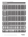
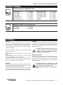
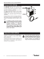
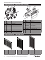
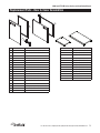
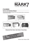
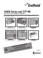
18600 Series and CTP-NB Service and Installation Manual Please read this manual completely before attempting to install or operate this equipment! Notify carrier of damage! Inspect all components immediately. See page 2. 18600PTL 18600PTBM Pizza Tables with LiquiTec® Rail Pizza Tables with Raised Rail 18600PDL ® Work Table with Backsplash Dual LiquiTec N CAUTIO Rail Prep Table 18600BSTM 18600BUCM Work Tables CTP-NB Countertop Condiment Rail TION A M R O T INF N A T R O USE IMP E R O F E ONS! I T C READ B U R INST E S E H T AVE S E S A E PL July 2012 18600 and CTP-NB Series Service and Installation Manual Important Warning And Safety Information WARNING Read This Manual Thoroughly Before Operating, Installing, Or Performing Maintenance On The Equipment. WARNING Failure To Follow Instructions In This Manual Can Cause Property Damage, Injury Or Death. WARNING Do Not Store Or Use Gasoline Or Other Flammable Vapors Or Liquids In The Vicinity Of This Or Any Other Appliance. WARNING Unless All Cover And Access Panels Are In Place And Properly Secured, Do Not Operate This Equipment. WARNING This Appliance Is Not Intended For Use By Persons Who Lack Experience Or Knowledge, Unless They Have Been Given Supervision Or Instruction Concerning Use Of The Appliance By A Person Responsible For Their Safety. WARNING This Appliance Is Not To Be Played With. Warning Do Not Clean With Water Jet. WARNING Do Not Use Electrical Appliances Inside The Food Storage Compartment Of This Appliance. CAUTION Observe the following: 2 • Minimum clearances must be maintained from all walls and combustible materials. • Keep the equipment area free and clear of combustible material. • Allow adequate clearance for air openings. • Operate equipment only on the type of electricity indicated on the specification plate. • Unplug the unit before making any repairs. • Retain this manual for future reference. For customer service, call (800) 733-8829, (800) 773-8821, Fax (989) 773-3210, www.delfield.com 18600 and CTP-NB Series Service and Installation Manual Contents Serial Number Information Receiving & Inspecting Equipment....................................................... 3 Specifications......................................................................................... 4 Refrigerant Charges............................................................................... 5 Installation ............................................................................................. 5 Operation 18600PTBM & PTL Series................................................................. 6 18600BUCM & BSTM Series............................................................. 6 The serial number on 18600 Series units is located on the electrical specifications tag affixed inside the compressor section next to the pressure control. The serial number on CTP-NB Series units is located on the front of the unit. Always have the serial number of your unit available when calling for parts or service. 18600PDL Series................................................................................ 7 Warranty may be deemed invalid if other than authorized OEM (original equipment manufacture) replacement parts are used in Delfield equipment. CTP-NB Series.................................................................................... 7 Pressure Control Settings...................................................................... 8 Temperature Control Settings................................................................ 8 Care And Cleaning.............................................................................9-10 Wiring Diagram ©2012 The Delfield Company. All rights reserved. Reproduction without written permission is prohibited. “Delfield” is a registered trademark of The Delfield Company. 18600PTBM & PTL Series............................................................... 11 18600BUCM & BSTM Series........................................................... 12 18600PDL......................................................................................... 12 CTP-NB Series.................................................................................. 13 Replacement Parts..........................................................................14-23 Regulatory Certifications The models are certified by: Standard Labor Guidelines.................................................................. 24 Standard Warranties.......................................................................25-27 National Sanitation Foundation (NSF) Underwriters Laboratories (UL) Receiving And Inspecting The Equipment Even though most equipment is shipped crated, care should be taken during unloading so the equipment is not damaged while being moved into the building. 1. Visually inspect the exterior of the package and skid or container. Any damage should be noted and reported to the delivering carrier immediately. 2. If damaged, open and inspect the contents with the carrier. 3. In the event that the exterior is not damaged, yet upon opening, there is concealed damage to the equipment notify the carrier. Notification should be made verbally as well as in written form. 4. Request an inspection by the shipping company of the damaged equipment. This should be done within 10 days from receipt of the equipment. 5. Check the lower portion of the unit to be sure legs or casters are not bent. 6. Also open the compressor compartment housing and visually inspect the refrigeration package. Be sure lines are secure and base is still intact. 7. Freight carriers can supply the necessary damage forms upon request. 8. Retain all crating material until an inspection has been made or waived. Uncrating the Equipment First cut and remove the banding from around the crate. Remove the front of the crate material, use of some tools will be required. If the unit is on legs remove the top of the crate and lift the unit off the skid. If the unit is on casters it can be "rolled" off the skid. For customer service, call (800) 733-8829, (800) 773-8821, Fax (989) 773-3210, www.delfield.com 3 18600 and CTP-NB Series Service and Installation Manual Specifications 18600PTBM Pizza tables with raised rail 1/3 Pan Size Capacity Model # Of Doors # Of Shelf Max Shelf Area Storage Shelves Load (LBS) FT2 Cap. FT3 BTU Load Base/Rail BTU Sys. Cap. Base/Rail H.P. Voltz/Hertz/ Phase Amps NEMA Plug Ship Weight LBS/KG 18648PTBM 6 (1) 27” 1 124 3.95 10.23 470/441 2001/952 1/4 115/60/1 10.0 5-15P 520/236 18660PTBM 7 19” & 27” 2 70/124 6.51 15.12 694/617 2409/1208 1/3 115/60/1 12.0 5-15P 575/260 2 18672PTBM 9 (2) 27” 18691PTBM 11 (2)27” & (1) 19” 3 124 7.9 18.10 776/794 2967/1587 1/2 115/60/1 14.0 5-20P 635/288 124/70 10.29 24.48 1062/1058 3537/1865 1/2 115/60/1 14.0 5-20P 770/350 18699PTBM 12 (3) 27” 3 124 11.85 27.46 1144/1147 3537/1945 1/2 115/60/1 14.0 5-20P 805/365 186114PTBM 14 (3) 32” 3 140 14.46 33.05 1297/1323 5169/2433 3/4 115/60/1 16.0 5-20P 927/420 18600BUCM Work tables Model # Of Doors # Of Shelf Max Shelf Area Storage Shelves Load (LBS) FT2 Cap. FT3 BTU Load Base/Rail BTU Sys. Cap. Base/Rail H.P. Voltz/Hertz/ Phase Amps NEMA Plug Ship Weight LBS/KG 18648BUCM (1) 27” 1 124 3.95 10.23 475/NA 1462/NA 1/5 115/60/1 8.0 5-15P 390/177 18660BUCM 19” & 27” 2 70/124 6.51 15.12 686/NA 1462/NA 1/5 115/60/1 8.0 5-15P 435/197 18672BUCM (2) 27” 2 18691BUCM (2)27” & (1) 19” 3 124 7.90 18.10 856/NA 2261/NA 1/4 115/60/1 10.0 5-15P 495/225 124/70 10.29 24.48 1169/NA 2261/NA 1/4 115/60/1 10.0 5-15P 535/243 18699BUCM (3) 27” 3 124 11.85 27.46 1220/NA 2591/NA 1/3 115/60/1 12.0 5-15P 594/269 186114BUCM (3) 32” 3 106 14.46 37.24 1373/NA 2591/NA 1/3 115/60/1 12.0 5-15P 685/310 18600BSTM Work table with backsplash Model # Of Doors # Of Shelf Max Shelf Area Storage Shelves Load (LBS) FT2 Cap. FT3 BTU Load Base/Rail BTU Sys. Cap. Base/Rail H.P. Voltz/Hertz/ Phase Amps NEMA Plug Ship Weight LBS/KG 18648BSTM (1) 27” 1 124 3.95 10.23 475/NA 1462/NA 1/5 115/60/1 8.0 5-15P 390/177 18660BSTM 19” & 27” 2 70/124 6.51 15.12 686/NA 1462/NA 1/5 115/60/1 8.0 5-15P 435/197 18672BSTM (2) 27” 2 18691BSTM (2)27” & (1) 19” 3 124 7.90 18.10 856/NA 2261/NA 1/4 115/60/1 10.0 5-15P 495/225 124/70 10.29 24.48 1169/NA 2261/NA 1/4 115/60/1 10.0 5-15P 535/243 18699BSTM (3) 27” 3 124 11.85 27.46 1220/NA 2591/NA 1/3 115/60/1 12.0 5-15P 594/269 186114BSTM (3) 32” 3 106 14.46 37.24 1373/NA 2591/NA 1/3 115/60/1 12.0 5-15P 685/310 18600PTL Pizza table with LiquiTec® rail 1/3 Pan Size Capacity Model # Of Doors # Of Shelf Max Shelf Area Storage Shelves Load (LBS) FT2 Cap. FT3 BTU Load Base/Rail BTU Sys. Cap. Base/Rail H.P. Voltz/Hertz/ Phase Amps NEMA Plug Ship Weight LBS/KG 18648PTL 6 (1) 27” 1 124 3.95 10.23 470/441 2001/952 1/4 115/60/1 10.0 5-15P 520/236 18672PTL 9 (2) 27” 2 124 7.90 18.10 776/794 2967/1587 1/2 115/60/1 14.0 5-20P 635/288 18699PTL 12 (3) 27” 3 124 11.85 27.46 1144/1147 3537/1945 1/2 115/60/1 14.0 5-20P 805/365 18600PDL Pizza table with Dual LiquiTec® rails 1/3 Pan Size Capacity Model # Of Doors # Of Shelf Max Shelf Area Storage Shelves Load (LBS) FT2 Cap. FT3 BTU Load Base/Rail BTU Sys. Cap. Base/Rail H.P. Voltz/Hertz/ Phase Amps NEMA Plug Ship Weight LBS/KG 18648PDL 6 (1) 27” 1 124 3.95 10.23 424/1058 2001/1865 1/5, 1/3 115/60/1 10.1 5-20P 691/313 18672PDL 9 (2) 27” 2 124 7.90 18.10 703/1588 2001/3174 1/5, 1/2 115/60/1 12.7 5-20P 873/396 CTP-NB Counter top containment rail 1/3 Pan Size Capacity Model # Of Adapter Bars BTU Load BTU System Capacity H.P. Voltz/Hertz/ Phase Amps NEMA Plug Ship Weight LBS/KG CTP8146-NB 4 5 305 523 1/5 115/60/1 4.0 5-15P 121/54.9 CTP8160-NB 6 7 462 653 1/5 115/60/1 4.0 5-15P 158/71.7 4 For customer service, call (800) 733-8829, (800) 773-8821, Fax (989) 773-3210, www.delfield.com 18600 and CTP-NB Series Service and Installation Manual Refrigerant Charges Refrigerant Charges For 18600 Series Units: 18648-PTBM & PTL . . . . . . . . . . 16 oz. (454g) 18660-PTBM . . . . . . . . . . . . . . . 24 oz. (680g) 18672-PTBM & PTL . . . . . . . . . . 32 oz. (907g) 18691-PTBM . . . . . . . . . . . . . . . 32 oz. (907g) 18699-PTBM & PTL . . . . . . . . . . 32 oz. (907g) 186114-PTBM . . . . . . . . . . . . . 48 oz. (1361g) 18648-BUCM & BSTM . . . . . . . . 16 oz. (454g) 18660-BUCM & BSTM . . . . . . . . 16 oz. (454g) 18672-BUCM & BSTM . . . . . . . . 16 oz. (454g) 18691-BUCM & BSTM . . . . . . . . 16 oz. (454g) 18699-BUCM & BSTM . . . . . . . . 24 oz. (680g) 186114-BUCM & BSTM . . . . . . . 24 oz. (680g) 18648PDL . . . . . . . . . . . . . . . . 40 oz. (1134g) 18672PDL . . . . . . . . . . . . . . . . 56 oz. (1588g) Refrigerant Charges For CTP-NB Series Units: CTP8146-NB . . . . . . . . . . . . . . . . 8 oz. (227g) CTP8160-NB . . . . . . . . . . . . . . . . 8 oz. (227g) CTP8175-NB . . . . . . . . . . . . . . . 16 oz. (454g) Installation Location These units are intended for indoor use only. Be sure the location chosen has a floor strong enough to support the total weight of the cabinet and contents. A fully loaded 72” long model may weigh as much as 1200 pounds. Reinforce the floor as necessary to provide for maximum loading. Plumbing Self-contained models are standard with a condensate evaporator. If, for some reason, a unit does not have a condensate evaporator, or the evaporator fails, the unit’s drain must have an outlet to an appropriate drainage area or container. For the most efficient refrigeration, be sure to provide good air circulation inside and out. CAUTION Inside cabinet: Do not pack refrigerator so full that air cannot circulate. Outside cabinet: Be sure that the unit has access to ample air. Avoid hot corners and locations near stoves and ovens. It is recommended that the unit be installed no closer than 1” from any wall. PDL models also require 14” (36cm) clearance at the top and 6” (15cm) clearance at the bottom (casters). Leveling A level cabinet looks better and will perform better because the drain pan will drain properly, the doors will line up with the frames properly, and the cabinet will not be subject to undue strain. Some models have casters for your convenience, for ease of cleaning underneath and for mobility. It is important that the unit be installed in a stable condition with the front casters locked before operating. Moisture collecting from improper drainage can create a slippery surface on the floor and a hazard to employees. It is the owner’s responsibility to provide a container or outlet for drainage. Electrical connection Refer to the amperage data on page 3, the serial tag, your local code or the National Electrical Code to be sure the unit is connected to the proper power source. A protected circuit of the correct voltage and amperage must be run for connection of the line cord, or permanent connection to the unit. The power switch must be turned to OFF and the unit disconnected from the power source whenever performing service or maintenance functions. Never operate the unit without the louvered panel in place! For customer service, call (800) 733-8829, (800) 773-8821, Fax (989) 773-3210, www.delfield.com 5 18600 and CTP-NB Series Service and Installation Manual Operation: 18600PTBM & PTL Series Product should be loaded into the unit with care. Failure to heed these recommendations could result in damage to the interior of the cabinet or the blower coil. This unit is equipped with two on/off switches located behind the louvered machine compartment panel. The unit’s compressor and all evaporator fans will begin operating when the main power switch is turned to the ON position. Temperature ranges for the base are 36°F to 40°F. The switch labeled rail is for the raised rail. The rail switch is accessible through a 1.5” diameter hole in the louvered panel. Turning this switch to the ON position will activate the refrigeration for the rail. Temperature ranges for the raised rail are 33°F to 41°F. Product located in the rail must be removed at the end of day. This allows you to turn the rail off at night to save energy and the rail will have time to defrost as needed. All R404A models have a high pressure limiting device. Under severe overloading conditions, or in the event of a condenser fan failure or a plugged or blocked condenser, this device may shut down the refrigeration system. This device will automatically reset, but determining the cause of the high pressure condition should be investigated by a qualified refrigeration technician. Refrigerator Evaporator Fan Operation When the refrigerator is initially powered up or immediately following a power outage the unit will begin cooling after a 3-6 minute delay. During normal operation the evaporator fan pulses independently of the compressor as dictated by the controller as follows: 1. During the cooling mode, compressor and evaporator fan run simultaneously. 2. During the compressor off mode, evaporator fan pulses three minutes on and three minutes off. 3. During an actual defrost event other than the off-cycle defrost, compressor stays off but the evaporator fan runs continuously. A minimum of one hour of off time per day with the pans removed from the rail is required to properly defrost the rail. The power must be turned to OFF and the unit disconnected from the power source whenever performing service or maintenance functions. Never operate the unit without the louvered panel in place! Cooling Cycle Compressor On Evap Fan On Evap Fan Off Defrost Cycle Compressor Off Evap Fan On Evap Fan Off Cycles On 3-Min, Off 3-Min X Compressor Off Evap Fan On Evap Fan Off X Operation: 18600BUCM & BSTM Series After turning the ON/OFF switch to ON, the units compressor will begin operating. Delfield refrigerated bases are designed to maintain an operational temperature of 36°F to 40°F. Product should be loaded into the unit with care. Failure to heed these recommendations could result in damage to the interior of the cabinet or the blower coil. Overloading the storage area, restricting the air flow and continuous opening and closing of the doors and drawers will hamper the units ability to maintain operational temperature. Refrigerator Evaporator Fan Operation When the refrigerator is initially powered up or immediately following a power outage the unit will begin cooling after a 3-6 minute delay. During normal operation the evaporator fan pulses independently of the compressor as dictated by the controller as follows: 1. During the cooling mode, compressor and evaporator fan run simultaneously. 2. During the compressor off mode, evaporator fan pulses three minutes on and three minutes off. 3. During an actual defrost event other than the off-cycle defrost, compressor stays off but the evaporator fan runs continuously. Cooling Cycle Compressor On Evap Fan On Evap Fan Off X 6 For customer service, call (800) 733-8829, (800) 773-8821, Fax (989) 773-3210, www.delfield.com Defrost Cycle Compressor Off Evap Fan On Evap Fan Off Cycles On 3-Min, Off 3-Min Compressor Off Evap Fan On X Evap Fan Off 18600 and CTP-NB Series Service and Installation Manual Operation: 18600PDL Series Product should be loaded into the unit with care. Failure to heed these recommendations could result in damage to the interior of the cabinet or the blower coil. This unit is equipped with two on/off switches located behind the louvered machine compartment panel. The unit’s compressor and all evaporator fans will begin operating when the main power switch is turned to the ON position. Temperature ranges for the base are 36°F to 40°F (2°C to 4°C). The switch labeled rail is for the raised rails. The rail switch is accessible through a 1.5” (3.8cm) diameter hole in the louvered panel. Turning this switch to the ON position will activate the refrigeration for the rails. Temperature ranges for the raised rails are 33°F to 41°F (0.5°C to 5°C). Product located in the rails must be removed at the end of day. This allows you to turn the rails off at night to save energy and the rails will have time to defrost as needed. A minimum of one hour of off time per day with the pans removed from the rails is required to properly defrost the rails. The power must be turned to OFF and the unit disconnected from the power source whenever performing service or maintenance functions. Never operate the unit without the louvered panel in place! All R404A models have a high pressure limiting device. Under severe overloading conditions, or in the event of a condenser fan failure or a plugged or blocked condenser, this device may shut down the refrigeration system. This device will automatically reset, but determining the cause of the high pressure condition should be investigated by a qualified refrigeration technician. Refrigerator Evaporator Fan Operation When the refrigerator is initially powered up or immediately following a power outage the unit will begin cooling after a 3-6 minute delay. During normal operation the evaporator fan pulses independently of the compressor as dictated by the controller as follows: 1. During the cooling mode, compressor and evaporator fan run simultaneously. 2. During the compressor off mode, evaporator fan pulses three minutes on and three minutes off. 3. During an actual defrost event other than the off-cycle defrost, compressor stays off but the evaporator fan runs continuously. Cooling Cycle Compressor On Evap Fan On X Evap Fan Off Defrost Cycle Compressor Off Evap Fan On Evap Fan Off Cycles On 3-Min, Off 3-Min Compressor Off Evap Fan On Evap Fan Off X Operation: ctp-nb Series The unit is equipped with one on/off switch located on the right end of the unit. The unit’s compressor will begin operating when this switch is turned to the ON position. Temperature ranges for the rail are 33°F to 41°F. Product located in the rail must be removed at the end of day. This allows you to turn the rail OFF at night to save energy and the rail will have time to defrost as needed. A minimum of one hour of off time per day with the pans removed from the rail is required to properly defrost the rail. The power switch must be turned to OFF and the unit disconnected from the power source whenever performing service or maintenance functions. Never operate the unit without the louvered panel in place! For customer service, call (800) 733-8829, (800) 773-8821, Fax (989) 773-3210, www.delfield.com 7 18600 and CTP-NB Series Service and Installation Manual Pressure Control Settings The factory recommended low-pressure control settings for 18600PTBM’s are: 55psi cut-in and 30psi cut-out to maintain proper temperature for product in the rail. The interior temperature is controlled by the thermostat mounted in the mechanical compartment. The factory recommended low-pressure control settings for 18600PTL’s are: 20psi (1.38bar) cut-in and 10psi (0.70bar) cut-out. The base and rail temperatures are controlled by the thermostats mounted in the machine compartment. A pressure control is located in the machine compartment. An adjustable control has the word COLDER on the knob, with an arrow to indicate the adjustment direction. These controls are field adjustable and do not require a service agent. In attempting to adjust the pressure control, you can do damage to your unit by accidentally adjusting the differential. Please make small incremental adjustments if a temperature adjustment is necessary, please contact the service department at Delfield (800) 733-8829 or your local service agent. Delfield is not responsible for charges incurred while having the pressure control adjusted. Temperature Control Settings A thermostat controls temperature in the 18600PTBM base, 18600PTL base, 18600PTL rail, BUCM, BSTM, 18600PDL base and 18600PDL rail. Thermostats are located in the machine compartment. They are field adjustable and do not require a service agent. The factory setting is 2.5. Set toward 1 for higher temperatures and toward 7 for lower temperatures. 8 Please make small incremental adjustments if a temperature adjustment is necessary. Contact the service department at Delfield +1 (989) 7737981 or your local service agent for additional assistance. Delfield is not responsible for charges incurred while adjusting the thermostat. For customer service, call (800) 733-8829, (800) 773-8821, Fax (989) 773-3210, www.delfield.com 18600 and CTP-NB Series Service and Installation Manual Care & Cleaning Door Gasket Maintenance Door gaskets require regular cleaning to prevent mold and mildew build up and also to retain the elasticity of the gasket. Gasket cleaning can be done with the use of warm soapy water. Avoid full strength cleaning products on gaskets as this can cause them to become brittle and crack. Never use sharp tools or knives to scrape or clean the gasket. Gaskets can be easily replaced and do not require the use of tools or an authorized service person. The gaskets are “Dart” style and can be pulled out of the groove in the door and new gaskets can be “pressed” back into place. Drain Maintenance - Base Each unit has a drain located inside the unit that removes the condensation from the evaporator coil and routes it to an external condensate evaporator pan. Each drain can become loose or disconnected during normal use. If you notice water accumulation on the inside of the unit be sure the drain tube is connected to the evaporator drain pan. If water is collecting underneath the unit make sure the end of the drain tube is in the condensate evaporator in the machine compartment. The leveling of the unit is important as the units are designed to drain properly when level. Be sure all drain lines are free of obstructions. Drawer Maintenance Drawer Assembly Cleaning The drawer assembly is designed to be cleaned easily. Both drawer and tracks are removable without tools. The drawer tracks are dishwasher safe or can be cleaned in a sink with detergents and a soft bristle brush. Drawers and tracks should be cleaned on a weekly basis. Remove Drawers Pull the drawer box out until it stops. Lift up on the drawer front and pull the drawer box completely out. Using a soft bristle brush, clean the track on the bottom of the drawer box. When finished, it should be wiped clean of all food and debris. Tracks The drawer box assembly must be removed. Pull the drawer tracks out until they hit a stop. Locate blue safety clips towards the back of each drawer track. Blue safety clips have a tab on the top. Push the tab back until it clicks. Lift up and pull the drawer tracks all the way out of the drawer cage. The drawer tracks are dishwasher safe tab on top of or can be cleaned in a sink blue safety clip with detergents and a soft bristle brush. Drawers and tracks should be cleaned on a weekly basis. Using a soft bristle brush, wash the track making sure each roller is thoroughly cleaned. The drawer cage should be cleaned with a soft bristle brush, removing any food and debris gathered on the bottom ledge. Once it’s cleaned thoroughly with a soft bristle brush, wipe remaining debris clean with a soft towel. Reassembly Push the drawer tracks into the drawer cage. The blue safety clip must remain pushed towards the back. Lift up and slide the drawer track all the way into the drawer cage. The blue safety clip will lock in place automatically. Once all tracks are replaced, insert the drawer box. Rest the drawer box bottom track on the front track roller. Then push the drawer back in place SLOWLY. When the drawer box is about half way in you will hit a STOP. You must lift the front of the drawer up approximately ½” (1.3cm) to continue inward. Clean tracks as often as possible. The cleaner the tracks are the better they will operate. Caster Maintenance Wipe casters with a damp cloth monthly to prevent corrosion. The power switch must be turned to OFF and the unit disconnected from the power source whenever performing service, maintenance functions or cleaning the refrigerated area. Refrigerators and Freezers The interior and exterior can be cleaned using soap and warm water. If this isn’t sufficient, try ammonia and water or a nonabrasive liquid cleaner. When cleaning the exterior, always rub with the “grain” of the stainless steel to avoid marring the finish. Do not use an abrasive cleaner because it will scratch the stainless steel and can damage the breaker strips and gaskets. Stainless Steel Care and Cleaning To prevent discoloration of rust on stainless steel several important steps need to be taken. First, we need to understand the properties of stainless steel. Stainless steel contains 70- 80% iron, which will rust. It also contains 12-30% chromium, which forms an invisible passive film over the steels surface, which acts as a shield against corrosion. As long as the protective layer is intact, the metal is still stainless. If the film is broken or contaminated, outside elements can begin to breakdown the steel and begin to form discoloration of rust. Proper cleaning of stainless steel requires soft cloths or plastic scouring pads. NEVER USE STEEL PADS, WIRE BRUSHES OR SCRAPERS! Cleaning solutions need to be alkaline based or non-chloride cleaners. Any cleaner containing chlorides will damage the protective film of the stainless steel. Chlorides are also commonly found in hard water, salts, and household and industrial cleaners. If cleaners containing chlorides are used be sure to rinse repeatedly and dry thoroughly. Routine cleaning of stainless steel can be done with soap and water. Extreme stains or grease should be cleaned with a non-abrasive cleaner and plastic scrub pad. Always rub with the grain of the steel. There are stainless steel cleaners available which can restore and preserve the finish of the steels protective layer. Early signs of stainless steel breakdown are small pits and cracks. If this has begun, clean thoroughly and start to apply stainless steel cleaners in attempt to restore the passivity of the steel. Never use an acid based cleaning solution! Many food products have an acidic content, which can deteriorate the finish. Be sure to clean the stainless steel surfaces of ALL food products. Common items include, tomatoes, peppers and other vegetables. Cleaning the Condenser Coil In order to maintain proper refrigeration performance, the condenser fins must be cleaned of dust, dirt and grease regularly. It is recommended that this be done at least every three months. For customer service, call (800) 733-8829, (800) 773-8821, Fax (989) 773-3210, www.delfield.com 9 18600 and CTP-NB Series Service and Installation Manual Care & Cleaning, continued If conditions are such that the condenser is totally blocked in three months, the frequency of cleaning should be increased. Clean the condenser with a vacuum cleaner or stiff brush. If extremely dirty, a commercially available condenser cleaner may be required. Continuous opening and closing of the doors will hamper the unit’s ability to maintain optimum refrigeration temperature. Top section is not intended for overnight storage. Product should be removed from pans. Pans can remain in unit while empty. Failure to maintain a clean condenser coil can initially cause high temperatures and excessive run times. Continuous operation with a dirty or clogged condenser coil can result in compressor failure. Neglecting the condenser coil cleaning procedures will void any warranties associated with the compressor and cost to replace the compressor. Never use a high-pressure water wash for this cleaning procedure as water can damage the electrical components located near or at the condenser coil. Doors/Hinges Over time and with heavy use doors the hinges may become loose. If this happens tighten the screws that mount the hinge brackets to the frame of the unit. Loose or sagging doors can cause the hinges to pull out of the frame, which may damage both the doors and the hinges. In some cases this may require qualified service agents or maintenance personnel to perform repairs. Do not place hot pans on/against the blue ABS liner. Do not throw items into the storage area. Failure to follow these recommendations could result in damage to the interior of the cabinet or to the blower coil. Overloading the storage area, restricting the airflow, and continuous opening and closing of the doors and drawers will hamper the units ability to maintain operational temperature. Refrigerated rail units Product in the rail should be removed to the refrigerated base at the end of the day. This allows you to turn the rail off at night to save energy and to defrost the rail. It also helps maintain product quality. The standard wrapped refrigerated rail units are controlled by a lowpressure control that is set to maintain the proper rail temperature. An on/off switch is also provided for the rail and is required to be shut off at night. With a LiquiTec rail a thermostat is provided to maintain rail temperature as well as the rail on/off switch. The LiquiTec rail is required to be shut off at night as well to allow for defrosting. To ensure product quality in the rail it is recommended that product be rotated every four hours. If adding any item to the unit, be sure to keep in mind the location of the refrigeration lines on wrapped rail units. A refrigeration leak in a rail is extremely difficult and costly to repair. In some cases it cannot be repaired at all. Preventing blower coil corrosion To help prevent corrosion of the blower coil, store all acidic items, such as pickles and tomatoes, in sealable containers. Immediately wipe up all spills. Units with pans should be operated with pans in place. Operating the unit without all pans in place will lower efficiency and may damage the unit. 10 For customer service, call (800) 733-8829, (800) 773-8821, Fax (989) 773-3210, www.delfield.com 18600 and CTP-NB Series Service and Installation Manual Wiring Diagram - 18600PTBM Series Wiring Diagram - 18600PTL Series For customer service, call (800) 733-8829, (800) 773-8821, Fax (989) 773-3210, www.delfield.com 11 18600 and CTP-NB Series Service and Installation Manual Wiring Diagram - 18600bucM & bstM Series Wiring Diagram - 18600PDL Series 12 For customer service, call (800) 733-8829, (800) 773-8821, Fax (989) 773-3210, www.delfield.com 18600 and CTP-NB Series Service and Installation Manual Wiring Diagram - ctp-nb series N L1 G POWER SWITCH CONDENSING UNIT TEMPERATURE CONTROLS THE CONDENSING UNIT For customer service, call (800) 733-8829, (800) 773-8821, Fax (989) 773-3210, www.delfield.com 13 18600 and CTP-NB Series Service and Installation Manual 18600PTBM Replacement Parts All 18600PTBM Models 3234290 1" Shelf Support 9321132 1.5" Shelf Support Screw 3234160 Caster, 5, Plate ,Swivel 3234161 Caster, 5, Plate, Swivel, Break 3234392 Hinge, Pan Cover, Center 3234282 Hinge, Pan Cover, End, LH 3234266 Hinge, Pan Cover, End, RH 2190154 Switch, Rocker, 20A/125V, *000-BN5-0030 Assembly, 1/4 HP Condensing Unit *000-BN5-0037 Assembly, 1/3 Condensing Unit *000-BN5-0035 Assembly, 1/2 HP Condenser, Med 186114PTBM Assembly, 3/4 HP Condenser, Med Assembly, Dr, Ref, 19X26, LT, 430 *000-187-007X Assembly, Dr, Ref, 19X26, RT, 430 *000-187-0082 Assembly, Dr, Ref, 27X26, LT, 430 *000-187-0081 Assembly, Dr, Ref, 27X26, RT,430 *000-187-0084 Assembly, Dr, Ref, 32X26, LT, 430 X *000-187-0083 Assembly, Dr, Ref, 32X26, RT, 430 X *000-402-004Q Assembly, Hinged Cover, 6 Pan, RT *000-402-004V Assembly, Hinged Cover, 8 Pan *000-402-004U Assembly, Hinged Cover, 8 Pan, RT *000-402-004X Assembly, Hinged Cover, 10 Pan, LT X X Assembly, Hinged Cover, 10 Pan, RT Assembly, Hinged Cover, 12 Pan *000-402-0051 Assembly, Hinged Cover, 12 Pan, LT *000-402-0052 Assembly, Hinged Cover, 12 Pan, RT *000-282-006I Assembly, Control, Tstat & Pressure Control *000-282-006D Assembly, Tstat & Low Pressure Control *000-282-006C Assembly, Tstat & Low Pressure Control *000-248-0030 Coil Assembly, R404A *000-248-0037 Coil Assembly, R404A, Fan Lt *359-478-003C Panel, Louver, 14.0, PTB *359-478-003E Panel, Louver, 15.0, PTB *359-478-003D Panel, Louver, 18.0, PTB 3977984 Shelf, Wire, 19X32DP 3977983 Shelf, Wire, 32X32 DP 3978014 Shelf, Wire, Coated 18660PTBM 18648PTBM X X X X X X X X X X X X X X X X X X X X X X X X X X X X X X X X X X X X X X X X X X X *Exploded assemblies and part prints are on pages 17-22. 14 18672PTBM X X *000-BN5-0036 *000-402-004Y 18691PTBM X *000-187-007Y *000-402-0050 18699PTBM For customer service, call (800) 733-8829, (800) 773-8821, Fax (989) 773-3210, www.delfield.com X X X X 18600 and CTP-NB Series Service and Installation Manual 18600BUCM Replacement Parts All 18600BUCM Models 3234290 1" Shelf Support 9321132 1.5" Shelf Support Screw 3234160 Caster, 5, Plate, Swivel 3234161 Caster, 5, Plate, Swivel, Brake *000-298-003P Control Assembly 186114BUCM 18699BUCM 18691BUCM 18672BUCM X X X 18660BUCM 18648BUCM X X *000-BN5-0031 Assembly, 1/5 Condensing Unit *000-BN5-0030 Assembly, 1/4 HP Condensing Unit *000-BN5-0037 Assembly, 1/3 Condensing Unit *000-187-007Y Assembly, Dr, Ref, 19X26, LT, 430 *000-187-007X Assembly, Dr, Ref, 19X26, RT, 430 *000-187-0082 Assembly, Dr, Ref, 27X26, LT, 430 X X X *000-187-0081 Assembly, Dr, Ref, 27X26, RT, 430 X X X X *000-187-0084 Assembly, Dr, Ref, 32X26, LT, 430 X *000-187-0083 Assembly, Dr, Ref, 32X26, RT, 430 X *000-248-0030 Coil Assembly, R404A X X X X X *000-248-0037 Coil Assembly, R404A, Fan Lt *359-478-0040 Panel, Louver, 14, Hanging *359-478-0042 Panel, Louver, 15, Hanging *359-478-0041 Panel, Louver, 18, Hanging 3977984 Shelf, Wire, 19X32DP 3977983 Shelf, Wire, 32X32DP 3978014 Shelf, Wire, Coated X X X X X X X X X X X X X X X X X X X *Exploded assemblies and part prints are on pages 17-22. For customer service, call (800) 733-8829, (800) 773-8821, Fax (989) 773-3210, www.delfield.com 15 18600 and CTP-NB Series Service and Installation Manual 18600BSTM & 18600PTL Replacement Parts All 18600BSTM Models 3234290 1" Shelf Support 9321132 1.5" Shelf Support Screw 3234160 Caster, 5, Plate, Swivel 3234161 Caster, 5, Plate, Swivel, Brake *000-298-003P Control Assembly *000-BN5-0031 Assembly, 1/5 Condensing Unit *000-BN5-0030 Assembly, 1/4 HP Condensing Unit *000-BN5-0037 Assembly, 1/3 Condensing Unit *000-187-007Y Assembly, Dr, Ref, 19X26, LT, 430 *000-187-007X Assembly, Dr, Ref, 19X26, RT, 430 *000-187-0082 Assembly, Dr, Ref, 27X26, LT, 430 X X X *000-187-0081 Assembly, Dr, Ref, 27X26, RT, 430 X X X X *000-187-0084 Assembly, Dr, Ref, 32X26, LT, 430 X *000-187-0083 Assembly, Dr, Ref, 32X26, RT, 430 X *000-248-0030 Coil Assembly, R404A X X X X X *000-248-0037 Coil Assembly, R404A, Fan Lt *359-478-0040 Panel, Louver, 14, Hanging *359-478-0042 Panel, Louver, 15, Hanging *359-478-0041 Panel, Louver, 18, Hanging 3977984 Shelf, Wire, 19X32DP 3977983 Shelf, Wire, 32X32DP 3978014 Shelf, Wire, Coated 186114BSTM 18699BSTM X 18691BSTM 18672BSTM X 18648BSTM X X X X X X X X X X X X X X X X X X X X All 18600PTL Models 3234290 1" Shelf Support 3516053 Coil, Solenoid, 120V 9321132 1.5" Shelf Support Screw 3234392 Hinge, Pan Cover, Center *000-187-0082 Assembly, Dr, Ref, 27X26, LT, 430 3234282 Hinge, Pan Cover, End, LH *000-402-0055 Assembly, Hinged Cover, 12 Pan, PTL 3234266 Hinge, Pan Cover, End, RH 263-ASB-0030 Bracket, Cutting Board, Center 3978014 Shelf, Wire, Coated 263-110-0034 Bracket, Cutting Board, LH 2190154 Switch, Rocker, 20A/125V 263-110-0036 Bracket, Cutting Board, RF 3516225 Valve, Expansion, Frz, 1/4Ton 3234160 Caster, 5, Plate, Swivel 3516102 Valve, Solenoid, 1/4ODF 3234161 Caster, 5, Plate, Swivel, Brake *000-BN5-0030 Assembly, 1/4 HP Condensing Unit *000-BN5-0035 Assembly, 1/2HP Condenser, MED *000-282-006L Assembly, Control, 15A *000-282-006M 18699PTL 18672PTL 18648PTL X X X Assembly, Control, 20A X X *000-187-0081 Assembly, Dr, Ref, 27X26, RT, 430 X X *000-402-0054 Assembly, Hinged Cover, 6 Pan, PTL *000-248-0030 Coil Assembly, R404A *000-248-0037 Coil Assembly, R404A, Fan Lt 16 18660BSTM X X X X For customer service, call (800) 733-8829, (800) 773-8821, Fax (989) 773-3210, www.delfield.com X X X 18600 and CTP-NB Series Service and Installation Manual CTP8000-NB & 18600PDL Replacement Parts All CTP8000-NB Models 243-ALS-0032 Divider, Bar, Cold 3234392 Hinge, Pan Cover, Center 3234282 Hinge, Pan Cover, End, LH 3234266 Hinge, Pan Cover, End, RH 9321374 Pin, Hinge, Salad Pan *000-254-Z000B Condenser Assembly, 1/5HP, CTP-8100 *000-AUX-0038 Condensing Unit Assembly, 1/5HP, CTP *223-016-Z000P Cover, Hinged, CTP *265-016-003U Cover, Pan, Rail, 8 Pan *265-016-003W Cover, Pan, Rail, 12 Pan 243-ALS-0030 Divider, Bar, Cold 243-ALS-0036 Divider, Bar, Cold *356-411-Z0009 Louver, Front, CTP-8100 X *026-411-Z000A Louver, Rear, CTP-8100 X *356-411-0004 Panel, Louver, Front CTP-8100 CTP8175-NB CTP8160-NB CTP8146-NB X X X X X X X X X X X All 18600PDL Models *000-187-0082 Assembly, Door, Ref, 27X26, LT, 430 3234266 Hinge, Pan Cover, End, RH *000-402-0054 Assembly, Hinged Cover, 6 Pan, PTL 9321374 Pin, Hinge, Salad Pan 263-110-0034 Bracket, Cutting Board 3978014 Shelf, Wire, Coated 263-110-0036 Bracket, Cutting Board 3234290 Support, Shelf, Plastic 3234186 Caster, 3DIA, Swivel, Plate 2190154 Switch, Rocker, 20A/125V 3234392 Hinge, Pan Cover 3516135 Thermometer, Hanging, 4 3234282 Hinge, Pan Cover, End, LH Part Number Description 18672PDL *000-BN5-003Y Assembly, 1/2-1/5 Cond Unit Stacked X 18648PDL *000-BN5-0040 Assembly, 1/3-1/5 Cond Unit Stacked X *000-282-006V Assembly, Control, L/T, 48” X *000-282-006K Assembly, Control, L/T, 72” X *000-187-0081 Assembly, Door, Ref, 27X26, RT, 430 X X *000-248-0030 Coil Assembly, R404A *000-248-0037 Coil Assembly, R404A, Fan Lt X *359-478-003E Panel, Louver, 15.0, PTB X *359-478-003D Panel, Louver, 18.0, PTB X *Exploded assemblies and part prints are on pages 17-22. For customer service, call (800) 733-8829, (800) 773-8821, Fax (989) 773-3210, www.delfield.com 17 18600 and CTP-NB Series Service and Installation Manual Replacement Parts - Control Assemblies Key 1 2 3 Part Number 000-282-006I 2193942 2190154 2194810 Key - Part Number 000-282-006C & 000-282-006D 2193927 2190154 2194810 1 2 3 Description Thermostat & Dual Pressure Control Assembly Dual pressure control Rocker switch, 20A/125V Control, Danfoss, GDM, 115V 1 2 3 Description Thermostat & Low Pressure Control Assembly 1 Low pressure control Rocker switch, 20A/125V Control, Danfoss, GDM, 115V 2 3 Key 1 2 Part Number 000-298-003P 2194810 2190154 Description Control Assembly Control, Danfoss, GDM, 115V Rocker switch, 20A/125V 1 Key 1 2 3 4 Part Number 000-282-006L & 000-282-006M 2193927 000-282-0051 2190154 2194810 Low pressure control Tstat Assembly, Danfoss, MK7 Rocker switch, 20A/125V Control, Danfoss, GDM, 115V Key 1 2 3 Part Number 000-282-006K 000-282-0051 2190154 2194810 Description 72” LiquiTec Dual Rail Control Assembly Tstat Assembly, Danfoss, MK7 Rocker switch, 20A/125V Control, Danfoss, GDM, 115V Key 1 2 3 Part Number 000-282-006V 000-282-0053 2190154 2194810 Description 48” LiquiTec Dual Rail Control Assembly Tstat Assembly, Danfoss, MK7 Rocker switch, 20A/125V Control, Danfoss, GDM, 115V 18 2 1 Description Control Assembly, LiquiTec, 2SW For customer service, call (800) 733-8829, (800) 773-8821, Fax (989) 773-3210, www.delfield.com 2 1 1 2 3 2 3 4 18600 and CTP-NB Series Service and Installation Manual Replacement Parts - Condensing Unit Assemblies 4 1 3 2 5 6 Part Number Description 000-AUX-0038 Condensing Unit Assembly, 1/5HP, CTP 3526694 Compressor 3516082 Condenser Coil - 000-BN5-0031 Assembly, 1/5 Condensing Unit 3516172 Fan Blade 1 3516457 Fan Blade 2162691 Fan Motor 2 2160020 Fan Guard 031-264-0000 Fan Motor Bracket 3 2162717 Fan Motor 3516191 Filter Drier 4 3526997 Compressor, Danfoss, TF4CLS Temp Control 5 2194787 Start Capacitor 6 3516322 Filter Dryer 7 075-231-0030 Condensate Pan 8 3516454 Condenser Coil 3516047 7 8 6 5 2 3 4 4 1 3 2 1 7 5 6 7 8 9 8 Key Part Number Description - 000-BN5-0035 Assembly, 1/2HP Condenser, Med - 000-BN5-0030 Assembly, 1/4 HP Condensing Unit 1 3516554 Condenser fan blade 1 3516457 Fan Blade 2 2160019 Condenser fan guard 2 2160020 Fan Guard 3 2162716 Condenser fan motor, 115V 3 2162717 Fan Motor 4 3516462 Capacitor, start-run assy 4 3526999 Compressor, Danfoss, NF5.5CLX 5 3527026 Compressor, Danfoss, SC12MLX 5 2194787 Start Capacitor 6 3516331 Hi pressure switch 6 3516322 Filter Dryer 7 3516322 Filter Drier 7 075-231-0030 Condensate Pan 8 075-231-0031 Pan, Condensate 8 3516454 Condenser Coil 9 3516455 Condenser coil For customer service, call (800) 733-8829, (800) 773-8821, Fax (989) 773-3210, www.delfield.com 19 18600 and CTP-NB Series Service and Installation Manual Replacement Parts - Condensing Unit Assemblies 1 2 1 3 2 3 4 5 4 5 8 6 7 Key Part Number Description Key Part Number Description - 000-BN5-0036 Assembly, 3/4 HP Condenser, Med - 000-BN5-0037 Assembly, 1/3 Condensing Unit 1 2160019 Guard, Fan, Wire 1 3516457 Fan Blade 2 3516442 Capacitor, Start, Run, Assembly 2 2160020 Fan Guard 3 3527021 Compressor, 3/4 HP Med 3 3527000 Compress, Danfoss, NF7CLS 4 3516322 Drier, Filter, (2)Inlet 4 2194788 Start Capacitor 5 3516456 Coil, Condenser, 3/4 HP 5 3516322 Filter Drier - 3516433 Blade, Fan, 25Deg, 10", CW 6 075-231-0030 Pan, Condensate - 2162716 Motor, Fan, 16W, 115V, CW 7 2162717 Fan Motor - 075-231-0031 Pan, Condensate, Sm 8 3516454 Condenser Coil 5 4 2 3 1 6 20 Key Part Number Description - 000-254-Z000B Condenser Assembly, 1/5HP, CTP-8100 1 3516082 Condenser Coil 2 3516172 Fan Blade 3 2162691 Fan Motor 4 3516047 Temp Control 5 3526694 Compressor 6 031-264-0000 Fan Motor Bracket - 3516191 Filter Drier For customer service, call (800) 733-8829, (800) 773-8821, Fax (989) 773-3210, www.delfield.com 18600 and CTP-NB Series Service and Installation Manual Replacement Parts - Condensing Unit Assemblies 000-BN5-003Y Assembly, 1/2-1/5 Stacked 3516433 Blade, Fan, 25Deg, 10", CW 3516457 Blade, Fan, 7.25 DIA. 2194789 Capacitor, Start, 240MFD 2194787 Capacitor, Start, 280MFD 3516455 Coil, Cond., 1/2 HP 3516454 Coil, Cond., 1/5, 1/4 3526997 Comp, 1/5HP, 115/60, R404A 3527001 Comp, SC12CLX.2, 115/60HZ 3516446 Compressor, Relay, Danfoss 3516322 Drier, Filter, (2) Inlet 2160020 Guard, Fan, 7.25 2160019 Guard, Fan, Wire 2162513 Motor, Fan, 35W, Blast 2162717 Motor, Fan, 9W, 115V, CW 3516193 Regulator, Pressure, 1/2 3516441 Relay, Compressor, SC12CLX.2 3516225 Valve, Exp, Frz, 1/4 Ton 000-BN5-0040 Assembly, 1/3-1/5 Stacked 3516457 Blade, Fan, 7.25 DIA. 2194787 Capacitor, Start, 280MFD 2194788 Capacitor, Start, 320MFD 3516454 Coil, Cond., 1/5, 1/4 3526997 Comp, 1/5HP, 115/60, R404A 3527000 Comp, NF7CLS, 115V/60HZ 3516446 Comp, Relay, Danfoss 3516322 Drier, Filter, (2) Inlet 2160020 Guard, Fan, 7.25 2162717 Motor, Fan, 9W, 115V, CW 3516193 Regulator, Pressure, 1/2 3516438 Relay, Comp, Ovld, NF7CLX 3516225 Valve, Exp, Frz, 1/4 Ton For customer service, call (800) 733-8829, (800) 773-8821, Fax (989) 773-3210, www.delfield.com 21 18600 and CTP-NB Series Service and Installation Manual Replacement Parts - Evaporator Coil Assembly 1 1 4 2 4 2 3 3 5 6 6 5 7 9 8 8 7 Key 1 2 3 4 5 6 7 8 - Part Number 000-248-0030 2160024 2160023 3516095 030-232-0003 3516273 030-233-0001 075-231-0033 030-234-0003 2184317 2194808 2194809 Description Coil Assembly, R404A, Ref Guard, fan, 4.7" Fan, axiel, 120V Coil, evaporator Back, evaporator, enclosure Expansion valve, 1/4, R-404a Side, coil, angled Drip pan, evaporator Front, coil Harness, coil Probe, Defrost, Danfoss, Control Probe, Temp, Sensor, Danfoss Key Part Number Description 1 2 3 4 5 6 7 8 9 - 000-248-0037 2160024 2160023 3516095 030-232-0003 000-BNH-0030 030-233-0038 3516273 030-234-0003 030-233-0039 2184317 2194808 2194809 Coil Assembly, R404A, Ref, Fan Lt Guard, fan, 4.7" Fan, axiel, 120V Coil, evaporator Back, evaporator, enclosure Drip pan, evaporator Side, coil, angled, Rt, Blank Expansion valve, 1/4, R-404a Front, coil Side, Coil, Angled, Lt, 2Fan Harness, coil Probe, Defrost, Danfoss, Control Probe, Temp, Sensor, Danfoss Replacement Parts - Louvered Panels Description Part Number Description Part Number Description 356-411-Z0009 Louver, Front, CTP-8100 359-478-003C Panel, Louver, 14.0, PTB 359-478-0040 Panel, Louver, 14, Hanging 026-411-Z000A Louver, Rear, CTP-8100 359-478-003E Panel, Louver, 15.0, PTB 359-478-0042 Panel, Louver, 15, Hanging 356-411-0004 Panel, Louver, Front CTP-8100 359-478-003D Panel, Louver, 18.0, PTB 359-478-0041 Panel, Louver, 18, Hanging Part Number 22 For customer service, call (800) 733-8829, (800) 773-8821, Fax (989) 773-3210, www.delfield.com 18600 and CTP-NB Series Service and Installation Manual Replacement Parts - Door & Cover Assemblies 2 1 1 2 Key Part Number Description Part Number Description - 000-187-007X Assembly, Dr, Ref, 19X26, RT, 430 000-402-0054 Assembly, Hinged Cover, 6 Pan, PTL 1 1701183 Gasket, Dr, 19, Mark7 000-402-004Q Assembly, Hinged Cover, 6 Pan, RT 2 0160179 Hinge Kit 000-402-004V Assembly, Hinged Cover, 8 Pan - 000-187-007Y Assembly, Dr, Ref, 19X26, LT, 430 000-402-004U Assembly, Hinged Cover, 8 Pan, RT Assembly, Hinged Cover, 10 Pan, LT 1 1701183 Gasket, Dr, 19, Mark7 000-402-004X 2 0160179 Hinge Kit 000-402-004Y Assembly, Hinged Cover, 10 Pan, RT - 000-187-0081 Assembly, Dr, Ref, 27X26, RT,430 000-402-0050 Assembly, Hinged Cover, 12 Pan 1 1701185 Gasket, Dr, 27, Mark7 000-402-0051 Assembly, Hinged Cover, 12 Pan, LT 2 0160179 Hinge Kit 000-402-0055 Assembly, Hinged Cover, 12 Pan, PTL - 000-187-0082 Assembly, Dr, Ref, 27X26, LT, 430 000-402-0052 Assembly, Hinged Cover, 12 Pan, RT 1 1701185 Gasket, Dr, 27, Mark7 223-016-Z000P Cover, Hinged, CTP Cover, Pan, Rail, 8 Pan Cover, Pan, Rail, 12 Pan 2 0160179 Hinge Kit 265-016-003U - 000-187-0083 Assembly, Dr, Ref, 32X26, RT, 430 265-016-003W 1 1701186 32" Door Gasket 2 0160179 Hinge Kit - 000-187-0084 Assembly, Dr, Ref, 32X26, LT, 430 1 1701186 32" Door Gasket 2 0160179 Hinge Kit For customer service, call (800) 733-8829, (800) 773-8821, Fax (989) 773-3210, www.delfield.com 23 18600 and CTP-NB Series Service and Installation Manual Standard Labor Guidelines To Repair Or Replace Parts On Delfield Equipment Advice and recommendations given by Delfield Service Technicians do not constitute or guarantee any special coverage. •A maximum of 1-hour is allowed to diagnose a defective component. •A maximum of 1-hour is allowed for retrieval of parts not in stock. •A maximum travel distance of 100 miles round trip and 2-hours will be reimbursed. •Overtime, installation/start-up, normal control adjustments, general maintenance, glass breakage, freight damage, and/or correcting and end-user installation error will not be reimbursed under warranty unless pre-approved with a Service Work Authorization from Delfield. You must submit the number with the service claim. LABOR OF 1-HOUR IS ALLOWED TO REPLACE: •Thermostat •Evaporator/Condenser Fan Motor and Blade •Door Hinges, Locks, and Gaskets •Compressor Start Components and Overload Protector •Thermometer • Solenoid Coil LABOR OF 2 HOURS TO REPLACE: •Drawer Tracks/Cartridges • Pressure Control •Solenoid Valve • Locate/Repair Leak LABOR OF 3 HOURS TO REPLACE: •Condenser or Evaporator Coil •Expansion Valve LABOR OF 4 HOURS TO REPLACE •Compressor This includes recovery of refrigerant and leak check. $55.00 maximum reimbursement for refrigerant recovery (includes recovery machine, pump, torch, oil, flux, minor fittings, solder, brazing rod, nitrogen or similar fees.) REFRIGERANTS •R404A A maximum of $15.00/lb. or$1.00/oz. will be reimbursed. 24 For customer service, call (800) 733-8829, (800) 773-8821, Fax (989) 773-3210, www.delfield.com 18600 and CTP-NB Series Service and Installation Manual Standard One Year Limited Warranty — One Year Parts, 90 Day Labor The Delfield Company (“Delfield”) warrants to the Original Purchaser of the Delfield product (herein called the “Unit”) that such Unit, and all parts thereof, will be free from defects in material and workmanship under normal use and service for a period of one (1) year from the date of shipment of the Unit to the Original Purchaser or one (1) year from the date of installation if registration is completed one (1) year from installation. During this one year warranty period, Delfield will repair or replace any defective part or portion there of returned to Delfield by the Original Purchaser which Delfield determines was defective due to faulty material or workmanship. Only during the first 90 days of the this one year warranty period, Delfield will, subject to the limits set forth below, pay labor, crating, and freight incurred in the removal of the Unit of defective component and shipment to Delfield. A maximum of 1-hour is allowed to diagnose a defective component. A maximum of 1-hour is allowed for retrieval of parts not in stock. A maximum travel distance of 100 miles round trip and 2-hours will be reimbursed. Overtime, installation/start-up, normal control adjustments, general maintenance, glass breakage, freight damage, delayed site entry because of security or hours of operation and/or correcting an enduser installation error will not be reimbursed under warranty unless pre-approved with a Service Work Authorization from Delfield. Delfield will pay the return costs if the Unit or part thereof was defective. The term “Original Purchaser” as used herein means that person, firm, association, or corporation for whom the Unit was originally installed. This warranty does not apply to any Unit or part thereof that has been subjected to misuse, neglect, alteration, or accident, such as accidental damage to the exterior finish, operated contrary to the recommendations specified by Delfield; or repaired or altered by anyone other than Delfield in any way so as to, in Delfield’s sole judgment, affect its quality or efficiency. This warranty does not apply to any Unit that has been moved from the location where it was originally installed. This warranty also does not cover the refrigerator drier, door gaskets or the light bulbs used in the Unit. The warranty is subject to the user’s normal maintenance and care responsibility as set forth in the Service and Installation Manual, such as cleaning the condenser coil, and is in lieu of all other obligations of Delfield. Delfield neither assumes, nor authorizes any other person to assume for Delfield, any other liability in connection with Delfield’s products. Removal or defacement of the original Serial Number or Model Number from any Unit shall be deemed to release Delfield from all obligations hereunder or any other obligations, express or implied. Parts furnished by suppliers to Delfield are guaranteed by Delfield only to the extent of the original manufacturer’s express warranty to Delfield. Failure of the Original Purchaser to receive such manufacturers warranty shall in no way create any warranty, expressed or implied, or any other obligation or liability on Delfield’s part in respect thereof. Under no condition does this warranty give the Original Purchaser the right to replace the defective Unit with a complete Unit of the same manufacturer or of another make. Unless authorized by Delfield in writing, this warranty does not permit the replacement of any part, including the motor-compressor, to be made with the part of another make or manufacturer. No claims can be made under this warranty for spoilage of any products for any reason, including system failure. The installation contractor shall be responsible for building access, entrance and field conditions to insure sufficient clearance to allow any hood(s), vent(s), or Unit(s) if necessary, to be brought into the building. Delfield will not be responsible for structural changes or damages incurred during installation of the Unit or any exhaust system. Delfield shall not be liable in any manner for any default or delay in performance hereunder caused by or resulting from any contingency beyond Delfield’s control, including, but not limited to, war, governmental restrictions or restraints, strike, lockouts, injunctions, fire, food, acts of nature, short or reduced supply of raw materials, or discontinuance of the parts by the original part manufacturer. Except as provided in any Additional Four Year Protection Plan, if applicable, and the Service Labor Contract, if applicable, the preceding paragraphs set forth the exclusive remedy for all claims based on failure of, or defect for Delfield products sold hereunder, whether the failure or defect arises before or during the warranty period, and whether a claim, however instituted, is based on contract, indemnity, warranty, tort (including negligence), strict liability, implied by statute, common-law or otherwise , and Delfield and its agents shall not be liable for any claims for personal injuries or consequential damages or loss, howsoever caused. Upon the expiration of the warranty period, all such liability shall terminate. THE FOREGOING WARRANTIES ARE EXCLUSIVE AND IN LIEU OF ALL OTHER WARRANTIES, WHETHER WRITTEN, ORAL, IMPLIED OR STATUTORY. NO IMPLIED WARRANTY OF MERCHANTABILITY OR FITNESS FOR PARTICULAR PURPOSE SHALL APPLY, DELFIELD DOES NOT WARRANT ANY PRODUCTS OR SERVICES OF OTHERS This warranty supersedes and excludes any prior oral or written representations or warranties. The sole and exclusive remedies of any person relating to the Unit, and the full liability of Delfield for any breach of this warranty, will be as provided in this warranty. Other than this Delfield Standard One Year Limited Warranty, any applicable Delfield Additional Four Year Protection Plan or applicable Delfield Service Labor Contract, the Original Purchaser agrees and acknowledges that no other warranties are offered or provided in connection with or for the Unit or any other part thereof. The liability of Delfield for breach of any warranty obligation hereunder is limited to: (i) the repair or replacement of the Delfield Product on which the liability is based, or with respect to services, re-performance of the services; or (ii) at Delfield’s option, the refund of the amount paid for said equipment or services. Any breach by Delfield with respect to any item or unit of equipment or services shall be deemed a breach with respect to that item or unit or service only IN NO EVENT WILL DELFIELD BE LIABLE FOR SPECIAL, INCIDENTAL OR CONSEQUENTIAL DAMAGES, OR FOR DAMAGES IN THE NATURE OF PENALTIES. If shipment of a replacement part is requested prior to the arrival in the Delfield factory of the part claimed to be defective, the Original Purchaser must accept delivery of the replacement part on a C.O.D. basis, with credit being issued after the part has been received and inspected at Delfield’s plant and determined by Delfield to be within this warranty. For customer service, call (800) 733-8829, (800) 773-8821, Fax (989) 773-3210, www.delfield.com 25 18600 and CTP-NB Series Service and Installation Manual 18600PDL One Limited Year Warranty (One Year Parts And Labor) The Delfield Company (“Delfield”) warrants to the Original Purchaser of the Delfield product (herein called the “Unit”) that such Unit, and all parts thereof, will be free from defects in material and workmanship under normal use and service for a period of one (1) year from the date of shipment of the Unit to the Original Purchaser or one (1) year from the date of installation if registration is completed one (1) year from installation. During this one year warranty period, Delfield will repair or replace any defective part or portion there of returned to Delfield by the Original Purchaser which Delfield determines was defective due to faulty material or workmanship. During this one year warranty period, Delfield will, subject to the limits set forth below, pay labor, crating, and freight incurred in the removal of the Unit of defective component and shipment to Delfield. A maximum of 1-hour is allowed to diagnose a defective component. A maximum of 1-hour is allowed for retrieval of parts not in stock. A maximum travel distance of 100 miles round trip and 2-hours will be reimbursed. Overtime, installation/start-up, normal control adjustments, general maintenance, glass breakage, freight damage, delayed site entry because of security or hours of operation and/or correcting an end-user installation error will not be reimbursed under warranty unless pre-approved with a Service Work Authorization from Delfield. Delfield will pay the return costs if the Unit or part thereof was defective. The term “Original Purchaser” as used herein means that person, firm, association, or corporation for whom the Unit was originally installed. This warranty does not apply to any Unit or part thereof that has been subjected to misuse, neglect, alteration, or accident, such as accidental damage to the exterior finish, operated contrary to the recommendations specified by Delfield; or repaired or altered by anyone other than Delfield in any way so as to, in Delfield’s sole judgment, affect its quality or efficiency. This warranty does not apply to any Unit that has been moved from the location where it was originally installed. This warranty also does not cover the refrigerator drier, door gaskets or the light bulbs used in the Unit. The warranty is subject to the user’s normal maintenance and care responsibility as set forth in the Service and Installation Manual, such as cleaning the condenser coil, and is in lieu of all other obligations of Delfield. Delfield neither assumes, nor authorizes any other person to assume for Delfield, any other liability in connection with Delfield’s products. Removal or defacement of the original Serial Number or Model Number from any Unit shall be deemed to release Delfield from all obligations hereunder or any other obligations, express or implied. Parts furnished by suppliers to Delfield are guaranteed by Delfield only to the extent of the original manufacturer’s express warranty to Delfield. Failure of the Original Purchaser to receive such manufacturers warranty shall in no way create any warranty, expressed or implied, or any other obligation or liability on Delfield’s part in respect thereof. Under no condition does this warranty give the Original Purchaser the right to replace the defective Unit with a complete Unit of the same manufacturer or of another make. Unless authorized by Delfield in writing, this warranty does not permit the replacement of any part, including the motor-compressor, to be made with the part of another make or manufacturer. No claims can be made under this warranty for spoilage of any products for any reason, including system failure. 26 The installation contractor shall be responsible for building access, entrance and field conditions to insure sufficient clearance to allow any hood(s), vent(s), or Unit(s) if necessary, to be brought into the building. Delfield will not be responsible for structural changes or damages incurred during installation of the Unit or any exhaust system. Delfield shall not be liable in any manner for any default or delay in performance hereunder caused by or resulting from any contingency beyond Delfield’s control, including, but not limited to, war, governmental restrictions or restraints, strike, lockouts, injunctions, fire, food, acts of nature, short or reduced supply of raw materials, or discontinuance of the parts by the original part manufacturer. Except as provided in any Additional Four Year Protection Plan, if applicable, and the Service Labor Contract, if applicable, the preceding paragraphs set forth the exclusive remedy for all claims based on failure of, or defect for Delfield products sold hereunder, whether the failure or defect arises before or during the warranty period, and whether a claim, however instituted, is based on contract, indemnity, warranty, tort (including negligence), strict liability, implied by statute, common-law or otherwise , and Delfield and its agents shall not be liable for any claims for personal injuries or consequential damages or loss, howsoever caused. Upon the expiration of the warranty period, all such liability shall terminate. THE FOREGOING WARRANTIES ARE EXCLUSIVE AND IN LIEU OF ALL OTHER WARRANTIES, WHETHER WRITTEN, ORAL, IMPLIED OR STATUTORY. NO IMPLIED WARRANTY OF MERCHANTABILITY OR FITNESS FOR PARTICULAR PURPOSE SHALL APPLY, DELFIELD DOES NOT WARRANT ANY PRODUCTS OR SERVICES OF OTHERS This warranty supersedes and excludes any prior oral or written representations or warranties. The sole and exclusive remedies of any person relating to the Unit, and the full liability of Delfield for any breach of this warranty, will be as provided in this warranty. Other than this Delfield Standard One Year Limited Warranty, any applicable Delfield Additional Four Year Protection Plan or applicable Delfield Service Labor Contract, the Original Purchaser agrees and acknowledges that no other warranties are offered or provided in connection with or for the Unit or any other part thereof. The liability of Delfield for breach of any warranty obligation hereunder is limited to: (i) the repair or replacement of the Delfield Product on which the liability is based, or with respect to services, re-performance of the services; or (ii) at Delfield’s option, the refund of the amount paid for said equipment or services. Any breach by Delfield with respect to any item or unit of equipment or services shall be deemed a breach with respect to that item or unit or service only IN NO EVENT WILL DELFIELD BE LIABLE FOR SPECIAL, INCIDENTAL OR CONSEQUENTIAL DAMAGES, OR FOR DAMAGES IN THE NATURE OF PENALTIES. If shipment of a replacement part is requested prior to the arrival in the Delfield factory of the part claimed to be defective, the Original Purchaser must accept delivery of the replacement part on a C.O.D. basis, with credit being issued after the part has been received and inspected at Delfield’s plant and determined by Delfield to be within this warranty. For customer service, call (800) 733-8829, (800) 773-8821, Fax (989) 773-3210, www.delfield.com 18600 and CTP-NB Series Service and Installation Manual Additional Four Year Protection Plan — For Motor-Compressor Only Delfield Model# Serial# Installation Date In addition to the Standard One Year Warranty on the MotorCompressor contained in the above listed Delfield product (the “Unit”), The Delfield Company (“Delfield”) also agrees to repair, or exchange with similar or interchangeable parts in design and capacity at Delfield’s option, the defective Motor-Compressor contained in the Unit (the “Motor-Compressor”), or any part thereof, for the Original Purchaser only, at any time during the four (4) years following the initial one (1) year period commencing on the date of installation for the Original Purchaser. This additional Warranty is only available if the Motor-Compressor is inoperative due to defects in material or factory workmanship, as determined by Delfield in its sole judgment and discretion. The Original Purchaser shall be responsible for returning the defective Motor-Compressor to Delfield prepaid, F.O.B. at the address shown on the back cover of this manual. The term “Original Purchaser” as used herein shall be deemed to mean that person, firm, association, or corporation for whom the equipment was originally installed. The term “Motor-Compressor” as used herein does not include unit base, air or water-cooled condenser, receiver, electrical accessories such as relay, capacitors, refrigerant controls, or condenser fan/motor assembly. This warranty does not cover labor charges incidental to the replacement of parts. This warranty further does not include any equipment to which said condensing unit is connected, such as cooling coils, temperature controls or refrigerant metering devices. This warranty shall be void if the Motor-Compressor, in Delfield’s sole judgment, has been subjected to misuse, neglect, alteration or accident, operated contrary to the recommendations specified by the Unit manufacturer, repaired or altered by anyone other than Delfield in any way so as, in Delfield’s sole judgment, to affect its quality or efficiency or if the serial number has been altered, defaced or removed. This Warranty does not apply to a Motor-Compressor in any Unit that has been moved from the location where it was originally installed. The addition of methyl chloride to the condensing unit or refrigeration system shall void this warranty. General Conditions Delfield shall not be liable in any manner for any default or delay in performance thereunder caused by or resulting from any contingency beyond Delfield’s control including, but not limited to, war, governmental restrictions or restraints, strikes, lockouts, injunctions, fire, floods, acts of nature, short or reduced supply of raw material or discontinuance of any part or the Motor-Compressor by the unit manufacturer. Replacement of a defective Motor-Compressor is limited to one (1) Motor-Compressor by us during the four (4) year period. Delfield shall replace the Motor-Compressor part only at no charge. This Warranty does not give the Original Purchaser of the MotorCompressor the right to purchase a complete re placement MotorCompressor of the same make or of another make. It further does not permit the replacement to be made with a Motor-Compressor of another kind unless authorized by Delfield. In the event Delfield authorizes the Original Purchaser to purchase a replacement MotorCompressor locally, only the wholesale cost of the Motor-Compressor is refundable. Expressly excluded from this warranty are damages resulting from spoilage of goods. Except as provided in any applicable Standard One Year Limited Warranty or applicable Service Labor Contract, the foregoing is exclusive and in lieu of all other war ran ties, whether written or oral, express or implied. This Warranty supersedes and excludes any prior oral or written representations or warranties. Delfield expressly disclaims any implied warranties of merchantability, fitness for a particular purpose or compliance with any law, treaty, rule or regulation relating to the discharge of substances into the environment. The sole and exclusive remedies of any person relating to the Motor-Compressor, and the full liability of Delfield for any breach of this Warranty, will be as provided in this Warranty. Other than any applicable Delfield Standard One Year Limited Warranty, this Delfield Additional Four Year Protection Plan and any applicable Delfield Service Labor Contract, the Original Purchaser agrees and acknowledges that no other warranties are offered or provided in connection with or for the Motor-Compressor or any part thereof. In no event will Delfield be liable for special, incidental or consequential damages, or for damages in the nature of penalties. For customer service, call (800) 733-8829, (800) 773-8821, Fax (989) 773-3210, www.delfield.com 27 Covington, TN Mt. Pleasant, MI Thank you for choosing Delfield! Help is a phone call away. Help our team of professional, courteous customer service reps by having your model number and serial number available at the time of your call (800) 733-8829. Model:________________________ S/N: _______________________ Installation Date:________________ For a list of Delfield’s authorized parts depots, visit our website at www.delfield.com. Delfield ™ ® 980 S. Isabella Rd., Mt. Pleasant, MI 48858, U.S.A. • (989) 773-7981 or (800) 733-8829 • Fax (989) 773-3210 • www.delfield.com Delfield reserves the right to make changes in design or specifications without prior notice. ©2012 The Delfield Company. All rights reserved. Printed in the U.S.A. DM18PTB 07/12