1
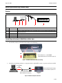
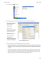
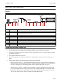
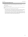
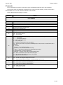
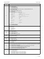
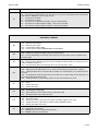
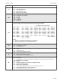
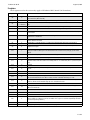
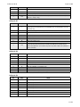
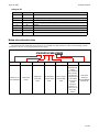
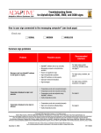
TechMemo
PRIORITY:
Normal
DATE:
August 26, 2004
TITLE:
US Robotics 56k modem setup for AlphaEclipse and Alpha signs
ECO REFERENCE:
PRODUCT(S)
AFFECTED:
SUMMARY:
#01-0011B
n/a
AlphaEclipse and Alpha signs. See “Alpha and AlphaEclipse sign data formats” on page 13 for a list of signs.
These instructions show how to set up a US Robotics V.90 or V.92 56K Faxmodem as either a transmitting or a
receiving modem in order to send messages to signs. This TechMemo replaces TechMemo #01-0011 and #97-0012.
• For AlphaEclipse sign modem setup, see page 1.
• For Alpha sign modem setup, see page 5.
Modems covered in this TechMemo
US Robotics V.90 56K Faxmodem
US Robotics V.92 56K Faxmodem
© Copyright 2001–2004 Adaptive Micro Systems LLC. All rights reserved.
Adaptive Micro Systems • 7840 North 86th Street • Milwaukee, WI 53224 USA • 414-357-2020 • 414-357-2029 (fax) • http://www.adaptivedisplays.com
Trademarked names appear throughout this document. Rather than list the names and entities that own the trademarks or insert a trademark symbol with each mention of the trademarked
name, the publisher states that it is using names for editorial purposes and to the benefit of the trademark owner with no intention of improperly using the trademark.
The following are trademarks of Adaptive Micro Systems: Adaptive, Alpha, AlphaLert, AlphaNET, AlphaNet plus, AlphaEclipse, AlphaPremiere, AlphaTicker, AlphaVision, AlphaVision
InfoTracker, Automode, BetaBrite, BetaBrite Director, BetaBrite Messaging Software, Big Dot, Director, EZ KEY II, EZ95, PagerNET, PPD, PrintPak, Serial Clock, Smart Alec, Solar, TimeNet.
The distinctive trade dress of this product is a trademark claimed by Adaptive Micro Systems LLC.
Due to continuing product innovation, specifications in this manual are subject to change without notice.
August 26, 2004
01-0011B
August 26, 2004
TechMemo 01-0011B
AlphaEclipse outdoor sign modem setup
Overview
Transmitting
modem
AlphaEclipse sign
Receiving modem (inside sign)
A
Item
Part #
A
—
B
—
C
D
E
1088-9301
—
1088-9301
C
B
D
D
E
Description
Computer running AlphaNET software (version 3.0 or greater).
Modem-to-computer DB9-to-DB25 cable (included with modem). A Belkin F2L088-06 6-foot DB9-to-DB25
cable can also be used.
Transmitting modem.
Phone line.
Receiving modem.
Transmitting modem setup for AlphaEclipse outdoor signs
1.
Set the DIP switches on the back of the modem to the following:
ON
Move switches #1, 3, 4, and 8 DOWN.
(Modem DIP switches are described on page 14.)
Figure 1: US Robotics 56K modem DIP switch settings
2.
Attach the transmitting modem to a computer that has AlphaNET version 3 or greater software installed.
To serial COM1
port
on computer
Connect modem to power supply,
but do not attach to a phone line.
Modem cable
(included with modem or use
Belkin F2L088-06 or equivalent)
Transmitting
modem
Figure 2: Modem-to-computer connection
2 of 24
TechMemo 01-0011B
August 26, 2004
3.
Start AlphaNET Diagnostics software:
4.
When the Diagnostics screen appears, click Modem. Then make the following selections:
Com Port Connected to Modem = the
computer COM port where the
modem is connected.
Baud Rate = 9600.
Data Format = 8,N,1.
Dialing Prefix = if a number, like 9, is
needed to get to an outside phone
line, enter the number here.
Number to Dial = the receiving
modem’s phone number.
Timeout (in Seconds) = 30
Configuration String =
AT&H0&R1&B1&N6&Y0&W0 (see
“Modem setup configuration string”
on page 24 for more information)
5.
Figure 3: AlphaNET modem setup
Click Configure Modem. One of the following two messages will appear:
•
Modem Configured Properly — The transmitting modem is ready for use. It can now be connected to a
phone line. If the receiving modem inside the sign has been set up and connected to a phone line, go to
“Modem test” on page 7. Otherwise, go to “Receiving modem setup for AlphaEclipse outdoor signs”
on page 4.
•
Modem Failed To Configure — Make sure that the modem is on and is connected to the correct COM
port on the computer. Repeat step 4, but this time watch the RD and SD lights on the modem. These
lights should flash when you click Configure Modem. If the “Modem Configured Properly” message
still does not appear, contact Adaptive Technical Support (800-719-2838).
3 of 24
August 26, 2004
TechMemo 01-0011B
Receiving modem setup for AlphaEclipse outdoor signs
The receiving modem inside a sign was set up at the factory. However, if you are having problems sending
messages to the sign and suspect the receiving modem, follow these steps:
1.
Remove power from the sign.
WARNING
Hazardous voltage.
Contact with high voltage
may cause death or serious
injury.
Always disconnect power to
unit prior to servicing. SM1000A
2.
Remove the receiving modem from the sign. (See “Related documentation” on page 13 for information on
a specific sign type.)
NOTE: If your transmitting and receiving modems are the same model, then you can attach the receiving
modem to the transmitting modem’s power supply. Otherwise, also remove the receiving
modem’s power supply from the sign.
3.
Set the receiving modem DIP switches (see Figure 1 on page 2).
4.
Connect the receiving modem to a computer (see Figure 2 on page 2).
5.
Configure the receiving modem as shown in Figure 3 on page 3.
NOTE: For the receiving modem, it is not necessary to enter a phone number after Number To Dial.
6.
Click Configure Modem. One of the following two messages will appear:
•
Modem Configured Properly — The receiving modem is ready for use. It can now be put back into the
sign. If the transmitting modem has been set up and connected to a phone line, go to “Modem test” on
page 7. Otherwise, go to “Transmitting modem setup for AlphaEclipse outdoor signs” on page 2.
•
Modem Failed To Configure — Make sure that the modem is on and is connected to the correct COM
port on the computer. Repeat step 4, but this time watch the RD and SD lights on the modem. These
lights should flash when you click Configure Modem. If the “Modem Configured Properly” message
still does not appear, contact Adaptive Technical Support (800-719-2838).
4 of 24
TechMemo 01-0011B
August 26, 2004
Alpha indoor sign modem setup
Overview
To next sign
Alpha sign
Transmitting
modem
B
A
C
Item
Part #
A
—
B
—
C
D
E
F
G
H
I
J
1088-9301
—
1088-9301
1088-8635
1088-1111
7122-0204
4331-0602
1086-8636
Receiving
modem
D
D
E
Alpha sign
F
G
H
I
J
Description
Computer running AlphaNET software (version 3.0 or greater).
Modem-to-computer DB9-to-DB25 cable (included with modem). A Belkin F2L088-06 6-foot DB9-to-DB25
cable or equivalent cable can also be used.
Transmitting modem.
Phone line.
Receiving modem.
Modem-to-Converter Box III DB25-to-DB9 cable, 10 feet.
Converter Box III, converts a modem’s RS232 signal to RS485 for signs.
RS485 indoor cable, 100-foot lengths.
Modular Network Adapter.
RS485 RJ11-to-RJ11 cable, 1-foot length.
Transmitting modem setup for Alpha signs
1.
Set the DIP switches on the back of the transmitting modem as shown in Figure 1 on page 2.
2.
Attach the transmitting modem to a computer that has AlphaNET version 3 or greater software installed
(see Figure 2 on page 2).
3.
Start AlphaNET Diagnostics software.
4.
When the Diagnostics screen appears, click Modem. Then make the selections as shown in Figure 3 on
page 3.
5.
Click Configure Modem. One of the following two messages will appear:
•
Modem Configured Properly — The transmitting modem is ready for use. It can now be connected to a
phone line. If the receiving modem has been set up and connected to a phone line, go to “Modem test”
on page 7. Otherwise, go to “Receiving modem setup for Alpha indoor signs” on page 6.
•
Modem Failed To Configure — Make sure that the modem is on and is connected to the correct COM
port on the computer. Repeat step 4, but this time watch the RD and SD lights on the modem. These
lights should flash when you click Configure Modem. If the “Modem Configured Properly” message
still does not appear, contact Adaptive Technical Support (800-719-2838).
5 of 24
August 26, 2004
TechMemo 01-0011B
Receiving modem setup for Alpha indoor signs
1.
Set the DIP switches on the back of the receiving modem as shown in Figure 1 on page 2.
2.
Attach the receiving modem to a computer that has AlphaNET version 3 or greater software installed (see
Figure 2 on page 2).
3.
Start AlphaNET Diagnostics software.
4.
When the Diagnostics screen appears, click Modem. Then make the selections as shown in Figure 3 on
page 3.
5.
Click Configure Modem. One of the following two messages will appear:
•
Modem Configured Properly — The receiving modem is ready for use. It can now be connected to a
phone line. If the transmitting modem has been set up and connected to a phone line, go to “Modem
test” on page 7. Otherwise, go to “Transmitting modem setup for Alpha signs” on page 5.
•
Modem Failed To Configure — Make sure that the modem is on and is connected to the correct COM
port on the computer. Repeat step 4, but this time watch the RD and SD lights on the modem. These
lights should flash when you click Configure Modem. If the “Modem Configured Properly” message
still does not appear, contact Adaptive Technical Support (800-719-2838).
6 of 24
TechMemo 01-0011B
August 26, 2004
Modem test
The following procedure tests to see if the transmitting and receiving modems are working correctly.
1.
Start AlphaNET Site Manager software and click Edit > Connection Device > Add. Then select the
appropriate connection device for the transmitting modem attached to your computer and click OK:
If the transmitting modem is
connected to COM 1 port, then select
Modem on Com 1 as shown here.
2.
Select Modem on Com 1 and click Make Default.
7 of 24
August 26, 2004
3.
TechMemo 01-0011B
Click Edit and set up the modem device as shown below:
Set COM Port = to the computer port that is
connected to the transmitting modem.
Select a Data format and Baud Rate — see “Alpha
and AlphaEclipse sign data formats” on page 13.
Dialing Prefix — if a number, like 9, is needed to get
to an outside phone line, enter the number here.
Figure 4: Modem connection device setup
4.
Click OK until just the Site Manager screen appears:
8 of 24
TechMemo 01-0011B
5.
August 26, 2004
From the Site Manager screen, click File > New Site. Set up the new site as shown below. Then click OK:
Site Name — name this new site
Modem Test.
Compatibility — see “Alpha and
AlphaEclipse sign data formats” on
page 13.
Use an Editor transmit site — check
this.
Connection Device = the modem
connection device you previously
created.
Phone Number — the telephone
number of the receiving modem. This
can include “9” and an area code if
necessary.
6.
With the Modem Test site selected, click Messages > Edit. Then type a short message in the AlphaNET
Message Editor window that appears:
7.
Send the test message to the sign by clicking File > Transmit > To Selected Sites > OK:
8.
If the test message does not appear on the sign, make sure the transmitting modem is on and connected to
the appropriate COM port on your computer. Also, try turning the sign off and then on again.
9 of 24
August 26, 2004
TechMemo 01-0011B
Advanced modem setup using Hyperterminal
Use this section when AlphaNET Diagnostics software is not available for modem setup or when greater
control is needed for modem setup.
NOTE: The AT commands used in this section only apply to US Robotics 56K V.90 and V.92 Faxmodems.
Though some of the AT commands used below might work with other modems, consult your
modem’s documentation for a list of AT commands specific to your modem.
Set up Hyperterminal
1.
Set the DIP switches on a US Robotics 56K Faxmodem as shown in Figure 1 on page 2.
2.
Connect the modem to your computer as shown in Figure 2 on page 2. Then turn the modem on.
3.
Start Hyperterminal:
4.
A “New Connection” must be created the first time Hyperterminal is used with a modem. When the
Connection Description window appears, type “Modem” after Name. Then click OK:
NOTE: Next time you open Hyperterminal, click Cancel at this window. Then click File > Open and select
Modem.ht.
10 of 24
TechMemo 01-0011B
August 26, 2004
5.
Select COM1 from the next screen and click OK:
6.
When the next window appears, set the communication parameters as shown below. Then click OK.
The baud rate (Bits per second)
is set high (57600) because the
modem will be communicating
with a computer not a sign.
7.
In the terminal window, type the command “ate1” (all lowercase) and then press the ENTER key:
NOTE: When typing commands, either use all lowercase (as above) or all uppercase letters. Mixing lowerand uppercase letters in a command may cause an error.
ate1 is called an “at command”:
• at = These two letters start most modem commands.
• e1 = The actual command. For a US Robotics Faxmodem,
this command tells the modem to display what you type.
Otherwise, you could not see the letters as you type.
11 of 24
August 26, 2004
TechMemo 01-0011B
Configure the modem
8.
Configure the user-defined Y0 modem template by typing “at&h0&r1&b1&n6&y0&w0”. (Use either
uppercase or lowercase letters. Do not mix both.)
9.
Check the modem’s Y0 settings. Type “ati5” and press ENTER. A screen similar to the following will
appear:
Template Y0 = user-defined values.
The values in rectangles in this
screen are all correct because they
match this command:
AT&H0&R1&B1&N6&Y0&W0 (see
“Modem setup configuration string”
on page 24 for more information)
10. Use an AT command to change any other values in template Y0. Remember to end the command with
&W0 so your settings are saved.
11. Review the changes you made by typing “ati5”.
12. Finally, type “aty0”. This tells the modem to use template Y0 when the modem is powered on or is reset.
12 of 24
TechMemo 01-0011B
August 26, 2004
Appendix
Related documentation
Part #
Manual title
9711-7001
AlphaEclipse 2500/2600 Series Sign Installation Manual
9711-6015
AlphaEclipse 3500 Series B Sign Installation Manual
9711-8001
AlphaEclipse 3600 Sign Installation Manual
9705-1002
Alpha Solar Installation and Operation Manual
9711-4201
AlphaPremiere 9000 Series Sign Installation Instructions
9702-2005
Director Sign User Manual
9708-8061
Alpha Sign Communications Protocol
Alpha and AlphaEclipse sign data formats
Compatibility
Data Format
(If there is more than one selection (Data bits,
for a sign, choose the rightmost
parity, stop
one.)
bits)
Model
EZ KEY Alpha 1
II
(EZ95)
Alpha
2.0
Alpha
3.0
7E2
Baud rate
8N1 1200 2400 4800 9600 19200 38400
Alpha 200 series (215R, 215C)
✓
✓
✓
✓
✓
✓
✓
✓
Alpha 220C
✓
✓
✓
✓
✓
✓
✓
✓
Alpha 300 series (320C, 330C)
✓
✓
✓
✓
✓
✓
✓
✓
Alpha 420C
✓
✓
✓
✓
✓
Alpha 430i, 440i, 460i, 790i
✓
✓
✓
✓
✓
Alpha 4000 series (4080R, 4120R, 4160R,
4200R, 4080C, 4120C, 4160C, 4200C)
✓
✓
✓
✓
✓
✓
✓
✓
Alpha 7000 series (7080C, 7120C, 7160C,
7200C)
✓
✓
✓
✓
✓
✓
✓
✓
AlphaEclipse 2500
✓
✓
✓
✓
✓
✓
✓
✓
✓
✓
✓
AlphaEclipse 2600
✓
✓
✓
✓
✓
✓
✓
✓
✓
✓
✓
AlphaEclipse 3500
✓
✓
✓
✓
✓
✓
✓
✓
✓
✓
✓
AlphaEclipse 3600
✓
✓
✓
✓
✓
✓
✓
✓
✓
✓
✓
✓
✓
✓
✓
AlphaPremiere
✓
✓
✓
✓
✓
✓
✓
✓
AlphaVision (full matrix)
✓
✓
✓
✓
✓
✓
✓
✓
AlphaVision (character matrix)
✓
✓
✓
✓
✓
✓
✓
✓
Betabrite
✓
✓
✓
✓
✓
✓
✓
✓
BigDot
✓
✓
✓
✓
✓
✓
✓
✓
Director
✓
✓
✓
✓
✓
✓
✓
✓
PPD (Personal Priority Display)
✓
✓
✓
✓
✓
✓
✓
✓
Solar
✓
✓
✓
✓
✓
✓
✓
✓
13 of 24
August 26, 2004
TechMemo 01-0011B
US Robotics V.90 and V.92 modem reference
DIP switches
DIP
switch
Setting
(UP = off,
DOWN = on)
AT
command
equivalent
Function
(US Robotics settings in italics. Adaptive settings in bold.)
UP
&D0
Normal DTR (Data Terminal Ready) operations — computer must provide DTR signal for the modem
to accept commands. Dropping the DTR terminates a call.
DOWN
&D1
DTR override — modem ignores DTR signal.
UP
V1
Use verbal result codes.
DOWN
V0
Use numeric result codes.
UP
Q1
Suppress result codes.
DOWN
Q0
Enable result codes.
UP
E1
Local echo on — display keyboard commands.
DOWN
E0
Local echo off
1
2
3
4
UP
5
S0 = 1
Auto answer on — modem will answer calls on the first ring (or the number of rings set in register
(or greater) S0). Also, modem AA LED will be on.
DOWN
S0 = 0
UP
&C1
Normal CD (Carrier Detect) operations — modem sends CD signal when it connects with another
modem. Modem drops CD on disconnect.
DOWN
&C0
Carrier detect override — CD always on. Modem CD LED will always be on.
6
UP
7
Auto answer off — modem will not answer calls. Modem AA LED will be off.
On modem powerup, load Yn template (default = Y0).
—
DOWN
On modem powerup, load &F0 generic template settings.
UP
8
Modem will not recognize AT commands (dumb mode).
—
DOWN
Modem will recognize AT commands (smart mode).
14 of 24
TechMemo 01-0011B
August 26, 2004
Default modem settings
These are the default or factory settings loaded into US Robotics 56K V.90 and V.90 Faxmodems:
A
B
C
D
E
Item
Name
A
atz4
ati4
B
B0
E0
F1
M1
Q0
V1
X4
Y0
Description
• atz4 — an AT command that resets the current modem settings to the factory hardware
settings. However, the atz4 command does not change the user-defined Y0 through Y4
settings.
• ati4 — an AT command that displays the modem’s current settings.
Basic command settings — see “AT commands” on page 16 for more information.
These basic commands can be set using either an AT command or by changing a DIP switch (see
“DIP switches” on page 14):
• E0 (DIP switch #4)
• Q0 (DIP switch #3)
• V1 (DIP switch #2)
A command set by a DIP switch can be changed using an AT command. However, when the
modem is powered off and on, the DIP switch setting is used.
C
BAUD=19200
PARITY=N
WORDLEN=8
Baud rate, parity, data format — these values are determined by the settings of the COM port
connected to the modem.
D
&A3, &B1, . . . &Y1
Ampersand (&) command settings — see “AT commands” on page 16 for more information.
E
S00=001 . . . S40=001
S registers — memory locations that contain various modem parameters — see “S registers” on
page 21.
15 of 24
August 26, 2004
TechMemo 01-0011B
AT commands
The AT commands used in this section only apply to US Robotics 56K V.90 and V.92 Faxmodems.
Though some of the AT commands used below might work with other modems, consult your modem’s
documentation for a list of AT commands specific to your modem.
NOTE: Modem default settings are in italics.
Command
Function
BASIC COMMANDS
$
Used with D, S, or & commands (or just AT) to display a basic command list.
A
Manual answer — goes off hook in answer mode. Pressing any key before a connection stops the operation.
A/
Re-executes the last command. Used mainly to redial. Does not require the AT prefix or a carriage return.
A>
Re-executes the last command continuously until a user intervenes. Otherwise, the command will execute forever. Does
not require the AT prefix or a carriage return.
+++
Escapes to online-command mode.
AT
Required prefix for most modem commands except A/, +++, and A>. Use AT alone to test for OK result code.
Bn
US/ITU-T answer sequence:
• B0 — ITU-T answer sequence.
• B1 — US answer tone.
Dn
Dials the specified phone number (for example, ATDT9,5551212). Includes the following:
• 0 - 9 — numeric digits.
• # , * — extended touch-pad tones.
• L — dials the last number dialed.
• P — pulse (rotary) dial.
• R — originates call using answer (reverse) frequencies.
• Sn — dials the phone number string stored in NVRAM at position n. Phone numbers are stored with the &Zn=s
command.
• T — tone dial.
• ,(comma) — pause. Linked to S8 register.
• ; (semicolon) — return to command mode after dialing.
• “ (quotes) — dials the letters that follow (in an alphabetical phone number).
• ! (exclamation point) — flashes the switch hook.
• / (backslash) — delays for 125 ms before proceeding with dial string.
• W — wait for second dial tone (X2 or X4). Linked to S6 register.
• @ — dials, waits for quiet answer, and continues (X3 or higher).
• $ — displays a list of dial commands.
En
Sets command mode echo (also controlled by DIP switch #4):
• E0 — echo off. Your typing will not appear on the screen.
• E1 — modem displays keyboard commands. Your typing will appear on the screen.
Fn
Sets online local echo — if on, a modem displays on your screen the data it is transmitting to another modem:
• F0 — online echo on. (Sometimes called half duplex.)
• F1 — online echo off. (Sometimes called full duplex.)
Hn
Goes on/off hook:
• H0 — hangs up (goes on hook)
• H1 — picks up (goes off hook).
16 of 24
TechMemo 01-0011B
August 26, 2004
Command
Function
Displays modem information:
• I0 — 4-digit product code.
• I1 — results of ROM checksum.
• I2 — results of RAM checksum.
• I3 — product type and firmware revision (for example, U.S. Robotics 56K FAX EXT V5.2.9).
• I4 — current modem settings.
• I5 — NVRAM settings for templates Y0 and Y1.
• I6 — link diagnostics.
• I7 — product configuration (see example below):
In
Product type
Product ID:
Options
Fax Options
Line Options
Clock Freq
EPROM
RAM
US/Canada External
00568604
V32bis,V.80,V.34+,x2,V.90,V.92
Class 1/Class 2.0
Caller ID, Distinctive Ring
92.0Mhz
256k
32k
FLASH date
FLASH rev
2/16/2001
5.2.9
DSP date
DSP rev
2/16/2001
5.2.9
• I9 — plug-and-play information.
• I11 — extended link diagnostics.
Ln
Sets speaker volume (internal modems only):
• L0 — low volume.
• L1 — low volume.
• L2 — medium volume.
• L3 — high volume.
Mn
Operates modem speaker:
• M0 — speaker always off.
• M1 — speaker on until connect.
• M2 — speaker always on.
• M3 — speaker on after dial until connect.
On
Returns online. Use with the escape code +++ to toggle between command and online modes:
• O0 — return online (normal).
• O1 — return online and retrain.
Qn
Enables or disables the display of result codes (also controlled by DIP switch #3):
• Q0 — display result codes.
• Q1 — suppress results codes.
Vn
Displays result codes in words or numbers (also controlled by DIP switch #2):
• V0 — use numeric codes.
• V1 — use words.
Xn
Controls the amount of information displayed in a result code:
• X0 — basic result codes: only use result codes 0 through 4 which are OK, CONNECT, RING, NO CARRIER, and ERROR.
Does not look for dial tone or busy signal.
• X1 — extended result codes (CONNECT speed codes). Does not look for dial tone or busy signal.
• X2 — extended result codes with NO DIAL TONE. Does not look for busy signal.
• X3 — extended result codes with BUSY. Does not check for dial tone.
• X4 — extended result codes with NO DIAL TONE and BUSY.
Yn
Selects power up/reset modem configuration. This works with DIP switch #7:
• Y0 — user-defined template 0.
• Y1 — user-defined template 1.
• Y2 — factory template 0 (generic). See also the &F0 command.
• Y3 — factory template 1 (hardware). See also the &F1 command.
• Y4 — factory template 2 (software). See also the &F2 command.
17 of 24
August 26, 2004
TechMemo 01-0011B
Command
Function
Zn
Resets modem. This works with DIP switch #7:
• Z0 — reset modem to Yn. If DIP switch #7 = UP (off), then Y0, Y1, Y2, or Y4 is selected based on the current value of Y.
If DIP switch #7 = DOWN (on), then Y3 settings are used.
• Z1 — reset modem to Y0 settings.
• Z2 — reset modem to Y1 settings.
• Z3 — reset modem to Y2 (factory generic settings). See also the &F0 command.
• Z4 — reset modem to Y3 (factory hardware settings). See also the &F1 command.
• Z5 — reset modem to Y4 (factory software settings). See also the &F2 command.
AMPERSAND (&) COMMANDS
&An
Enables/disables additional result code subsets (see Xn):
• &A0 — ARQ result codes disabled.
• &A1 — ARQ result codes enabled.
• &A2 — V.32 modulation indicator added.
• &A3 — Protocol indicators added (LAPM/MNP/NONE and V42bis/MNP5).
&Bn
Sets modem serial port rate:
• &B0 — variable: the serial port rate adapts to match the connection speed.
• &B1 — fixed: the modem always communicates with the computer at the rate which you have set regardless of the
connection speed.
&Cn
Controls Carrier Detect (CD) signal (also controlled by DIP switch #6):
• &C0 — CD signal override. Modem ignores the true status of the CD signal and responds as if it is always present. The
modem’s CD light will always be on.
• &C1 — normal operation. Modem sends CD signal when it connects with another modem.
&Dn
Controls Data Terminal Ready (DTR) signal (also controlled by DIP switch #1):
• &D0 — DTR signal override. Modem ignores the true status of the DTR signal and responds as if it is always on.
• &D1 — if DTR signal drops while in online data mode, the modem enters command mode, issues an OK, and remains
connected.
• &D2 — normal operation. If DTR signal drops while in online data mode, the modem hangs up. If the DTR signal is not
present, the modem will not answer or dial.
• &D3 — If DTR signal drops, the modem hangs up and resets as if an ATZ command were issued.
&Fn
Loads a factory setting:
• &F0 — generic.
• &F1 — hardware flow control.
• &F2 — software flow control.
&Gn
Sets guard tone:
• &G0 — no guard tone (US and Canada)
• &G1 — 550 Hz guard tone (some European countries). Requires B0 setting.
• &G2 — 1800 Hz guard tone (UK). Requires B0 setting.
&Hn
Sets Transmit Data (TD) flow control (see also &Rn):
• &H0 — flow control disabled.
• &H1 — hardware flow control: requires that your computer and software support the CTS signal.
• &H2 — software flow control: requires that your software supports XON/XOFF signaling.
• &H3 — hardware and software flow control.
&In
Sets Receive Data (RD) software flow control (see also &Rn):
• &I0 — software flow control disabled.
• &I1 — XON/XOFF signals to your modem and remote system.
• &I2 — XON/XOFF signals to your modem only.
18 of 24
TechMemo 01-0011B
August 26, 2004
Command
Function
&Kn
Enables or disables data compression:
• &K0 — data compression disabled.
• &K1 — auto enable/disable.
• &K2 — data compression enabled.
• &K3 — MNP5 compression disabled.
&Mn
Sets error control (ARQ) for connection 1200 bps and higher:
• &M0 — normal mode, error controlled.
• &M1 — reserved.
• &M2 — reserved.
• &M3 — reserved.
• &M4 — normal/ARQ.
• &M5 — ARQ mode.
Sets connect speed. If connection cannot be made at this speed, the modem will hang up. When used with &Un, and &Un
is greater than 0, &Nn sets the ceiling connect speed. &Un sets the floor connect speed:
&Nn
&N0 (see NOTE 1)
&N1 — 300 bps
&N2 — 1200 bps
&N3 — 2400 bps
&N4 — 4800 bps
&N5 — 7200 bps
&N6 — 9600 bps
&N7 — 12,000 bps
&N8 — 14,400 bps
&N9 — 16,800 bps
&N10 — 19,200 bps
&N11 — 21,600 bps
&N12 — 24,000 bps
&N13 — 26,400 bps
&N14 — 28,800 bps
&N15 — 31,200 bps
&N16 — 33,600 bps
(See NOTE 2 for &N17 through &N38)
&N17 — 28,800 bps &N24 — 37,333 bps &N31 — 46,666 bps
&N18 — 29,333 bps &N25 — 38,666 bps &N32 — 48,000 bps
&N19 — 30,666 bps &N26 — 40,000 bps &N33 — 49,333 bps
&N20 — 32,000 bps &N27 — 41,333 bps &N34 — 50,666 bps
&N21 — 33,333 bps &N28 — 42,666 bps &N35 — 52,000 bps
&N22 — 34,666 bps &N29 — 44,000 bps &N36 — 53,333 bps
&N23 — 36,000 bps &N30 — 45,333 bps &N37 — 54,666 bps
&N38 — 56,000 bps
NOTES:
1 — Variable rate. Connection speed determined by remote modem.
2 — &N17 through &N39 only apply to V.90 and V.92 modems.
&Pn
Sets pulse (rotary) dial make/break ratio:
• &P0 — US/Canada ratio, 39%/61%.
• &P1 — UK ratio, 33%/67%.
&Rn
Sets Receive Data (RD) hardware flow control Request To Send (RTS) (see also &Hn):
• &R0 — reserved.
• &R1 — modem ignores RTS.
• &R2 — received data to computer only on RTS.
&Sn
Controls Data Set Ready (DSR) operation:
• &S0 — DSR override. DSR signal is always on.
• &S1 — DSR signal only comes on during a connection.
&Tn
Loopback test commands:
• &T0 — ends testing.
• &T1 — analog loopback. If a connection exists when this command is issued, the modem hangs up. When the test
starts, a CONNECT message is displayed.
• &T2 — reserved.
• &T3 — local digital loopback. If no connection exists, ERROR is returned.
• &T4 — enables remote digital loopback.
• &T5 — prohibits remote digital loopback.
• &T6 — starts remote digital loopback. If no connection exists, ERROR is returned.
• &T7 — remote digital loopback with self test and error detector.
• &T8 — analog loopback with self test and error detector.
19 of 24
August 26, 2004
TechMemo 01-0011B
Command
Function
With n > 0, sets the floor connect speed, lowest acceptable connection speed. &Nn is the ceiling connect speed (&N=0
&U=0 connects at highest speed available):
If your modem cannot connect to the remote modem at or above the speed set with this command, the modem will hang
up.
&Un
&U0 (see NOTE 1)
&U1 — 300 bps
&U2 — 1200 bps
&U3 — 2400 bps
&U4 — 4800 bps
&U5 — 7200 bps
&U6 — 9600 bps
&U7 — 12,000 bps
&U8 — 14,400 bps
&U9 — 16,800 bps
&U10 — 19,200 bps
&U11 — 21,600 bps
&U12 — 24,000 bps
&U13 — 26,400 bps
&U14 — 28,800 bps
&U15 — 31,200 bps
&U16 — 33,600 bps
(See NOTE 2 for &U17 through &U38)
&U17 — 28,800 bps &U24 — 37,333 bps &U31 — 46,666 bps
&U18 — 29,333 bps &U25 — 38,666 bps &U32 — 48,000 bps
&U19 — 30,666 bps &U26 — 40,000 bps &U33 — 49,333 bps
&U20 — 32,000 bps &U27 — 41,333 bps &U34 — 50,666 bps
&U21 — 33,333 bps &U28 — 42,666 bps &U35 — 52,000 bps
&U22 — 34,666 bps &U29 — 44,000 bps &U36 — 53,333 bps
&U23 — 36,000 bps &U30 — 45,333 bps &U37 — 54,666 bps
&U38 — 56,000 bps
NOTES:
1 — No minimum connection speed.
2 — &U17 through &U39 only apply to V.90 modems.
&Wn
Modifies user-defined NVRAM settings:
• &W0 — modifies Y0 settings.
• &W1 — modifies Y1 settings.
&Yn
Determines how a modem responds when a break signal is received:
• &Y0 — destructive, non-expedited: data being processed by modem receiving break is destroyed, break is not sent to
other modem.
• &Y1 — destructive, expedited: data being processed by both modems is destroyed, break is sent to other modem.
• &Y2 — non-destructive, expedited: data being processed in both modems is not affected, break is sent to other
modem.
• &Y3 — non-destructive, non-expedited: data being processed in both modems is not affected, break is not sent to other
modem.
&Zn=s
Writes phone number s to user-defined NVRAM where n = 0 through 3.
&Zn?
Displays phone number in user-defined NVRAM at position n where n = 0 through 3.
20 of 24
TechMemo 01-0011B
August 26, 2004
S registers
The S registers used in this section only apply to US Robotics 56K V.90 and V.92 Faxmodems.
Register
Default value
Function
S0
0
Sets the number of rings on which to answer in auto answer mode. When S0 = 0, auto answer is disabled
(also controlled by DIP switch #5).
S1
0
Counts and stores the number of rings from an incoming call. S0 must be greater than 0.
S2
43
(“+” character)
S3
13
S4
10
Stores ASCII decimal value for the line feed character. Valid range is 0 through 127.
S5
8
Stores the ASCII decimal code for the backspace character. A value of 128 to 255 disables the backspace
delete function.
S6
2
Sets number of seconds a modem waits before dialing. If Xn is set to X2 or X4, then this is the timeout
length if there is no dial tone.
S7
60
Sets the number of seconds that the modem waits for a carrier signal. For international connections, this
number should be increased.
S8
2
Sets duration, in seconds, for pause (,) option in the dial command. Valid range is 0 through 32.
S9
6
Sets required duration, in tenths of a second, of remote modem’s carrier signal before your modem
recognizes this signal.
S10
7
Sets duration, in tenths of a second, that modem waits to hang up after loss of carrier. This guard time
allows your modem to distinguish a line disturbance from a true disconnect (hang up) by the remote
modem.
S11
55
Sets duration and spacing, in milliseconds, for tone dialing.
S12
50
Sets duration, in fiftieths of a second, of guard time for escape code sequence (+++).
S13
0
Bit-mapped register (see “Settings for S13” on page 22). Select the bit(s) you want on and set S13 to the
total of the values in the Value column. For example, ATS13 = 17 enables bit 0 (value is 1) and bit 4 (value
is 16).
S14
0
Reserved.
S15
0
Bit-mapped register setup. To set the register, see instructions for S13. See “Settings for S15” on
page 22.
S16
0
Reserved.
S17
0
Reserved.
S18
0
Test timer for &T loopback testing. Sets the time in seconds of testing before the modem automatically
times out and terminates the test. When set to 0, the timer is disabled. Valid range is 1-255.
S19
0
Sets duration, in minutes, for inactivity timer. This timer activates when there is no data activity on the
phone line. At time-out the modem hangs up. S19 = 0 disables the timer.
S20
0
Reserved.
S21
10
Sets length, in 10-millisecond units, of breaks sent from the modem to the computer. This applies to
MNP or V.42 mode only.
S22
17
Stores ASCII decimal code for the XON character.
S23
19
Stores ASCII decimal code for the XOFF character.
S24
0
Reserved.
S25
5
Sets duration, in hundredths of a second, of a true DTR drop. Prevents modem from interpreting random
glitches as DTR loss. (Most users will use the default. This register is useful for compatibility with older
systems and operating software.)
S26
0
Reserved.
S27
0
Bit-mapped register setup. See “Settings for S27” on page 23.
Stores the ASCII decimal code for the escape code character. A value of 128 to 255 disables the escape
code.
Stores ASCII decimal value for the carriage return character. Valid range is 0 through 127.
21 of 24
August 26, 2004
Register
TechMemo 01-0011B
Default value
S28
Function
0
Eliminates the V.32 answer tones for a faster connection.
8
Default item, all times are in tenths of seconds.
255
Disables all connections except V.32 at 9600 bps.
S29
20
Sets the duration, in tenths of a second, of the V.21 answer mode fallback timer.
S30
0
Reserved.
S31
128
Reserved.
S32
2
Bit-mapped register setup. To set this register, see the instructions for S13 (“Settings for S13” on
page 22).
S33
0
Bit-mapped register setup. To set this register, see the instructions for S13 (“Settings for S13” on
page 22).
S34
0
Reserved.
S35
0
Reserved.
S36
0
Reserved.
S37
0
Reserved.
S38
0
Sets an optional delay, in seconds, before a forced hang-up and clearing of the Transmit buffer when DTR
drops during an ARQ call. This allows time for a remote modem to acknowledge receipt of all transmitted
data before it is disconnected. The modem immediately hangs up when DTR drops. This option only
applies to connections terminated by dropping DTR. If the modem receives the ATH command, it ignores
S38 and immediately hangs up.
S39
0
Reserved.
S40
0
Reserved.
S41
0
Bit-mapped register setup. To set registers, see the instructions for S13 (“Settings for S13” on page 22).
S42
0
Reserved.
Bit-mapped registers
To set a bit-mapped register, select the bit(s) you want on and set the register (for example, S13) to the total of
the values in the Value column. For example, ATS13 = 17 enables bit 0 (value is 1) plus bit 4 (value is 16) = 1 + 16.
Settings for S13
Bit
Value
Result
0
1
Reset when DTR drops.
1
2
Reset non-MNP transmit buffer from 1.5K to 128 bytes.
2
4
Set backspace key to delete.
3
8
On DTR signal, autodial the number stored in NVRAM at position 0.
4
16
At power on/reset, autodial the number stored in NVRAM at position 0.
5
32
Reserved.
6
64
Disable quick retrains.
7
128
Disconnect on escape code.
Settings for S15
Bit
Value
Result
0
1
Disable ARQ/MNP for V.22.
1
2
Disable ARQ/MNP for V.22bis.
2
4
Disable ARQ/MNP V.32/V.32bis.
22 of 24
TechMemo 01-0011B
August 26, 2004
3
8
Disable MNP handshake.
4
16
Disable MNP level 4.
5
32
Disable MNP level 3.
6
64
MNP incompatibility.
7
128
Disable V.42 operation. To disable V.42 detect phase, select the sum of bits 3 and 7 (in other
words S15 = 136 [8 + 128]).
Settings for S27
Bit
Value
0
1
Enables ITU-T V.21 modulation at 300 bps for overseas calls. In V.21 mode, the modem
answers both overseas and domestic (US and Canada) calls, but only originates V.21 calls
(default Bell 103).
1
2
Enables unencoded (non-trellis coded) modulation in V.32 mode.
2
4
Disables V.32 modulation.
3
8
Disables 2100 Hz answer tone to allow two V.42 modems to connect faster.
4
16
Enables V.23 fallback mode.
5
32
Disables V.32bis mode.
6
64
Disable V.42 selective reject.
128
Software compatibility mode. This setting disables the codes and displays the 9600 code
instead. The actual rate of the call can be viewed on the ATI6 screen. Used for unusual
software incompatibilities. Some software may not accept 7200, 12,000, and 14,400 bps or
greater result codes.
7
Result
Settings for S32
Bit
Value
Result
0
1
V.8 Call Indicate enabled.
1
2
Enables V.8 mode.
2
4
Reserved.
3
8
Disable V.34, V.90, and V.92 modulation.
4
16
Disable V.34+ modulation.
5
32
Disable x2 modulation (select models only).
6
64
Disable V.90 modulation.
7
128
Disable V.92 modulation (select models only).
Settings for S33
Bit
Value
Result
0
1
Disable 2400 symbol rate.
1
2
Disable 2743 symbol rate.
2
4
Disable 2800 symbol rate.
3
8
Disable 3000 symbol rate.
4
16
Disable 3200 symbol rate.
5
32
Disable 3429 symbol rate.
6
64
Reserved.
7
128
Disable shaping.
23 of 24
August 26, 2004
TechMemo 01-0011B
Settings for S41
Bit
Value
Result
0
1
Distinctive ring enabled.
1
2
Speakerphone connect message override (voice products only).
2
4
Disable Digital Line Guard (56K internal faxmodems only).
3
8
Message waiting (voice products only).
4
16
Reserved.
5
32
Reserved.
6
64
Reserved.
7
128
Reserved.
Modem setup configuration string
The following AT commands are used to set up a US Robotics 56k modem as either a transmitting modem
(attached to a PC) or a receiving modem (inside a sign):
AT&H0&R1&B1&N6&Y0&W0
AT
Prefix for the rest
of the commands
&H0
Disable flow
control
&R1
Modem will
ignore RTS
signal.
&B1
Set the modem
serial port rate to
fixed.
&N6
&Y0
&W0
Set the connect
speed to 9600
baud.
Destructive, nonexpedited break
handling.
(This means that
when a break is
received, data
being processed
by the modem
receiving the
break is
destroyed.
However, the
break is not sent
to the other
modem.)
The previous
settings are
written to NVRAM
(template Y0).
24 of 24