1
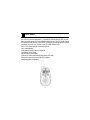
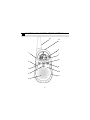
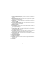
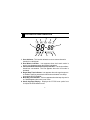
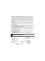
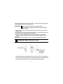
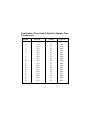
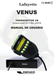
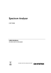
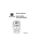
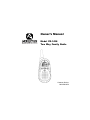
Owners Manual Model FR-1428 Two Way Family Radio Customer Service 1-800-290-6650 CONGRATULATIONS ON YOUR SELECTION OF THE FR-1428 (FAMILY RADIO) It is one of the most sophisticated and reliable two way family radios available. BEFORE OPERATING YOUR FR-1428 (FAMILY RADIO) READ THIS MANUAL CAREFULLY FEATURES Your FR-1428 Family Radio is a portable, easy to use, two-way radio that you can carry almost anywhere. It is skillfully constructed to give you reliable communications for many different applications. The FR-1428 is ideal for use around the house, in your boat, on hunting and camping trips, on the ski slopes or at the mall. Some of the FR-1428 features are: No Air Time Fees and No License Required Up to 2 Mile Range Auto Battery Saver and Auto Squelch 14 Channel, 38 CTCSS Multifunction LCD Display Continuous Tone Coded Squelch System (CTCSS) Talk Confirmation Tone and Call / Ring Button Interchangeable Faceplates -3- PERFORMANCE Your transceiver will achieve its maximum operating range when communicating with other transceivers in a flat open area with no trees or buildings obstructing its signal. Range may be up to two miles under such conditions. Obstacles such as buildings, trees or mountains will tend to reduce the transceiver’s effective range. FCC WARNING Replacement or substitution of transistors, diodes or other parts of a unique nature, with parts other than those recommended by the manufacturer, may cause a violation of the technical regulations of Part 15 of FCC Rules. SAFETY INFORMATION Your wireless handheld portable transceiver contains a low power transmitter. When the PTT button is pushed it sends out radio frequency (RF) signals. The device is authorized to operate at a duty factor not to exceed 50%. In August 1996, the Federal Communications Commissions (FCC) adopted RF exposure guidelines with safety levels for hand-held wireless devices. Important: To maintain compliance with the FCC’ s RF exposure guidelines hold the transmitter at least 1 inch (2.5 centimeters) from your face and speak in a normal voice, with the antenna pointed up and away. If you wear the handset on your body while using the headset accessory, use only the Audiovox supplied belt clip for this product and ensure that the antenna is at least 1 inch (2.5 centimeters) from your body when transmitting. Use only the supplied antenna. Unauthorized antennas, modifications, or attachments could damage the transmitter and may violate FCC regulations. Normal Position: Hold the transmitter approximately 1” from your face and speak in a normal voice, with the antenna pointed up and away. -4- FUNCTION AND LOCATION OF THE CONTROLS 13 12 6 1 7 8 2 9 3 10 4 11 5 -5- 1. Push-to-Talk Button (PTT): Press to transmit. Release to receive. 2. Monitor Button (M): Press and hold to bypass the squelch and listen to channel activity. 3. Up Button ( ): Press this button to increase the volume or channel setting. 4. Function Select Button (F): Press this button to select or scroll through all unit functions. 5. Built-In Speaker 6. LCD Display: Displays the current FRS channel number as well as other functions. 7. Power Button ( ): Press and hold this button for 2 seconds to turn the transceiver on or off. 8. Call Button (CALL): Press and hold this button to send a ringing sound to other radios tuned to the same channel. 9. Down Button ( ): Press this button to decrease the volume or channel setting. 10. Built-In Microphone 11. Snap-On Faceplate 12. Speaker Jack: For use with an Audiovox approved headset accessory only. 13. Antenna -6- LCD DISPLAY AND OPERATION 1 2 4 3 5 6 13 12 11 10 9 8 7 1. Scan Indicator: This function allows the user to scan a channel to search for a valid signal. 2. Dual Watch Indicator: Icon appears when dual watch mode is active. Icon disappears when the function is disabled. 3. Voice Activated Transmission (VOX) Indicator: This function allows hands-free conversation. The icon appears when the VOX mode is activated. 4. Roger Beep Tone Indicator: Icon appears when the roger beep tone is enabled, signifying transmission has been terminated. Icon disappears when tone is disabled. 5. Beep Key Tone Indicator: This icon appears when the beep key tone is on, and disappears when tone is not in use. 6. Small Segment Display: Displays the CTCSS tone option from 01-38) for the FRS channel in use. -7- 7. Receive/Transmit (RX/TX) Indicator: During receive, the left light ning symbol of this icon appears, together with the BUSY indication. During transmission, the right lightning symbol of this icon appears. 8. Busy Indicator: During signal reception or while in the monitor mode, this indication appears on the display, together with the RX lightning indication. 9. Call Indicator: This icon appears, together with the right lightning symbol, when the CALL button is pressed to indicate initiation of a call transmission. 10. Power Save Indicator: This icon appears to indicate the unit is in the power save mode to conserve battery power; it appears 5 seconds after the standby mode is activated. 11. Key Lock Indicator: This icon appears when the unit is placed in the key lock mode, to lock out all unit controls, except Power On/ Off, Backlight, Call and PTT. 12. Battery Level Indicator: This icon indicates the battery charge level on a scale of 1 to 3. 13. Large Segment Display: Indicates the FRS channel number in use. BATTERY INSTALLATION BELT CLIP IN RETRACTED POSITION BELT CLIP BATTERY COVER BATTERY POSITION WITH COVER REMOVED COVER LATCH -8- Your FR-1428 requires four “AAA” cells. Alkaline batteries will provide the best performance from your transceiver. CAUTION: Incorrect battery installation can damage the unit. Never attempt to charge alkaline batteries with the optional battery charger. 1.Lift and rotate belt clip counterclockwise (CCW) to the right to access battery cover. 2.Release battery cover latch and swing latch down; then lift the bottom of the battery cover and remove from the radio. 3.Insert four “AAA” alkaline batteries. Position batteries according to polarity markings. Reverse the procedure outlined in step 1 to reassemble. Note : Make sure the battery + and - terminals are aligned as shown. CHANGING SNAP-ON FACE PLATE FACE PLATE FACE PLATE MOUNTING SCREWS To change the snap-on face plate on the front of the unit, it is necessary to remove the battery compartment cover and batteries as previously described. Locate and loosen two screws on the upper part the battery tray. -9- CHANGING SNAP-ON FACE PLATE (CONTINUED) Pull out the face plate from the body of the transceiver using the groove located at the bottom of the speaker grill. Insert another face plate into the unit and install the two screws in the upper side of the tray in the battery compartment. Replace the batteries and cover. BATTERY SAVER MODE Your FR-1428 has a unique circuit designed to dramatically extend the life of its batteries. After 10 seconds of inactivity, the FR- 1428 will switch to battery saver ) is mode. While in battery saver mode, the battery saver mode indicator ( present on the display, and the transceiver will remain ready to receive any incoming transmissions while the battery saver mode is active. Pressing any of the buttons will exit the battery saver mode and illuminate the display. USING YOUR FR-1428 Turning the Transceiver On and Off ( ) Pressing the PWR button (7) for 2 seconds will activate the unit and ( on ) momentarily appears on the display followed by the frequency standby display. The speaker will sound a beep tone to confirm the transceiver’s activation. To turn the unit off, simply press and hold the power button for 2 seconds then release it. Volume Level Audio reception volume is controlled by the Up (s) and the Down (t) button. Momentarily pressing either button will increase or decrease the volume level. The display will indicate “LE” followed by “- 1” (lowest setting to “- 8” highest setting). Call Button (8) When the call button is pressed, the FR-1428 will transmit a 3-second ringing sound to other transceiver’s tuned to the same channel. This feature can be used to signal other parties that voice communication is desired. The call icon ) appears on the LED display while the call tone sounds. ( -10- Changing the Call Ring To select a favorite call ringer melody: 1. Press and hold the CALL button and, at the same time, press and hold the Power button for at least 2 seconds. 2. CA-01 will appear on the display. 3. Press the Up or Down button to select one of three call ringer melodies; each melody will sound as it is chosen. 4. Stop at the desired melody and press the Monitor (M) or PTT button to confirm your selection. Low Battery Alert ) flashes and produces When the battery level becomes low, the battery icon ( an audible tone every ten seconds. In this case, recharge or replace the batteries with new ones. Monitor Button (M) You can monitor channel activity by pressing the Monitor (M) button (2). If pressed for more than 2 seconds, you can continuously monitor channel activity. Press again, and channel activity monitoring is disabled. Function Select (F) Button Pressing the Function button will allow selection of frequency channels, as well as selection of the various unit functions. Each press permits selection of the desired channel (1–14), up to 38 CTCSS channel codes, Scan, Dual Watch, VOX, Roger Beep and Beep Tone functions. This button also activates the Key lock feature ( ) when pressed and held for more than 2 seconds. Channel Selection Press function button once until large two-digit channel display flashes. Press Up ( ) or Down ( ) buttons to select desired channel (1–14). CTCSS Selection To select a CTCSS channel code, press function button twice until small twodigit display flashes. Then press Up or Down button to select desired code (138) for that channel. The CTCSS primary code feature allows you to ignore transmissions from other transceivers that are using the same channel. How -11- ever, the same code must also be selected on those transceiverswith which you desire communication. In addition, this feature does not prevent others from listening to your transmissions. FUNCTIONS Channel Scanning Press the Function (F) button three times until the SC icon flashes. Press the Up ( ) button to enable the Scan function in the upward channel direction. Press the Down ( ) button to enable the Scan function in the downward channel direction. Once selected, the Scan icon (SC) will appear steadily on the display. While in Scan mode, the unit will pause on any active channel for 5 seconds, and then proceed to the next higher channel. The unit will scan channels 1–14 for activity and scanning will continue until the PTT, monitor, or call button is pressed. Dual Watch Mode This feature allows monitoring of two channels simultaneously. Press the Function (F) button four times until the Dual Watch icon (DW) flashes on the display. Using the Up ( ) or Down ( ) buttons, choose the alternate channel number you wish to monitor for activity. The channel display will now flash showing your current channel and alternate channel selection. To exit the dual watch mode, press the PTT button. When in Dual Watch mode, the unit will transmit on the channel on which it last received a signal. To communicate with someone on another channel, you must exit the Dual Watch mode and select the desired channel. VOX Function This feature enables you to have hands-free conversation. Press the Function (F) button five times until the Vox indicator (VOX) appears flashing and “on” or “oF” appears on the display. Then press Up ( ) or Down ( ) button to set the function on. Press the Monitor (M) or PTT button to confirm your selection.This feature enables you to have hands-free conversation. Whenusing the internal microphone/speaker or external microphone/headset (purchased separately), your voice or the signal is detected and the radio transmits and receives automatically. To turn off the VOX function, press the Function (F) button five times; then press the Up ( ) or Down ( ) button to turn the Vox function off. -12- VOX Sensitivity Level To set the VOX sensitivity level: 1. With the radio off, press the Function (F) button and, at the same time, press the Power button. 2. LE-03 (or 01-05), or dE-03 (or 01-05) will be displayed. If dE is displayed, press the Function (F) button and LE--- (level) will be displayed. 3. Press the Up or Down button to select from 1 to 5 voice sensitivity levels, with 1 being the most sensitive and 5 being the least sensitive. VOX Delay Adjustment To adjust the VOX delay: 1. Perform steps 1. through 3. above for VOX sensitivity level; then press the Function (F) button. 2. dE-03 (or 01-05) will be displayed. 3. Press the Up or Down button to select from 1 to 5 time delays, with 1 being the fastest and 5 being the slowest. 4. Press the Monitor (M) or PTT button to exit the VOX sensitivity/delay mode. Roger Beep Tone The unit will also transmit a beep tone sequence after each transmission to signal the receiving party that transmission has ended. This tone is called a “Roger Beep”. Press the press Function (F) button six times until the ( RGB ) icon flashes and “on” or “oF” appears. Then press Up ( ) or Down ( ) button to set the function on. The ( RGB ) icon will remain displayed. To disable the “Roger Beep”, proceed as before, until Beep Tone icon appears flashing. Then press Up ( ) or Down ( ) buttons to set the function to off. Press the PTT button to confirm your selection. Button Confirmation Tone Whenever the Up/Down or Function (F) select button is pressed, the speaker will sound a beep tone to confirm each press, provided the key tone feature is enabled. To disable the key tones, press Function button seven -13- times until the Beep Tone icon ( ) appears flashing and “on” or “oF” appears. Then press Up ( ) or Down ( ) to set the function off. Press the PTT button to confirm your selection. When “oF” is selected, no beep tones should be heard. To enable the key tones proceed as before, until Beep Tone icon appears flashing. The “On” icon will appear. Then press Up ( ) or Down ( ) button to set the function to on and the beep tones will be heard. Key Lock This feature prevents accidental change of unit settings. While enabled, Key Lock allows only the PTT button to operate. To enable Key Lock, press the Function (F) button for more than 2 seconds until ) appears. To disable the Key Lock function, press the Key Lock icon ( function button for more than 2 seconds until Key Lock icon disappears. To Transmit 1. Set the desired primary channel. 2. Press and hold the PTT (Push-to-Talk) button while speaking slowly and clearly in a normal voice, approximately 2 to 3 inches from the microphone. 3. The transmit lightning indicator ( ) will appear while transmitting. 4. Release the PTT (Push-to-Talk) button when you finish speaking to receive incoming signals. To Receive. 1. Set the desired channel. 2. Adjust the volume control to the desired listening volume by using the up and down buttons. 3. The transceiver will play strong received signals through its internal speaker or through a headset, if so equipped. 4. The receive lightning indicator ( ) will appear while transmitting. -14- Monitor Function The Monitor (M) button can be used to play all signals present on a channel. This is useful when communicating with other parties at extreme range. The monitor function can be locked on by pressing the Monitor (M) button for two seconds. When the monitor lock has been activated, the LCD display will indicate BUSY and the receive indicator lightning bolt appears. Pressing the monitor button a second time will unlock the monitor function. WARNING • Remove the batteries from the transceiver if it is not expected to be used for long periods. This will eliminate the possibility of battery acid leaking from the batteries and corroding the transceiver. • • Avoid exposing the unit to water or extremes of temperature. • Do not attempt to modify or in any way increase the output of this transceiver. Its output is designed to meet the legal limits set by the FCC. • Do not use this device or change its batteries in potentially explosive atmospheres as sparks in such areas could result in an explosion. • Turn your transceiver off wherever posted notices restrict the use of radios or cellular telephones. Facilities such as hospitals may use equipment that is sensitive to RF energy. • • Turn your transceiver off on-board aircraft when requested to do so. • This transceiver complies with F.C.C. regulations for use in the United States. Use in other countries may be prohibited or restricted by local regulation. Please check with the local regulating agency before using this device outside of the United States. Do not use this device in or near a mining facility, which uses remotely triggered explosives or in areas labeled “Blasting Area”. Premature or accidental detonation may result. Do not place your transceiver in front of a vehicle’s air-bag. If the air-bag deploys, it could propel the transceiver like a projectile. -15- SPECIFICATIONS* Channels: Channel Sub-Codes: Battery Life Alkaline: Power Source: Receiver 1.Sensitivity 2.Max. audio output @ 10% THD 3.Max. S/N ratio @ 1mV RF input 4.Squelch Sensitivity Threshold 7.Adjacent Channel Selectivity Transmitter 1.Maximum Effective Radiated Power 2.Audio Distortion 7.Hum and Noise 14 38 30 - 36 Hours 6.0 Vdc 120dBm Min. 110 mV 40 dB Min. -120 dBm Min. 50 dB MIn. 500 mW 3% 35 dB Min. * These specifications are subject to change without notice. They represent typical values, individual units may vary. Channel Frequencies: Channel MHz 1 462.5625 2 462.5875 3 462.6125 4 462.6375 5 462.6625 6 462.6875 7 462.7125 Channel 8 9 10 11 12 13 14 -16- MHz 467.5625 467.5875 467.6125 467.6375 467.6625 467.6875 467.7125 Continuous Tone Coded Squelch System Tone Frequencies CTCSS 1 2 3 4 5 6 7 8 9 10 11 12 13 14 15 16 17 18 19 Freq. Hz CTCSS 67.0 71.9 74.4 77.0 79.7 82.5 85.4 88.5 91.5 94.8 97.4 100.0 103.5 107.2 110.9 114.8 118.8 123.0 127.3 20 21 22 23 24 25 26 27 28 29 30 31 32 33 34 35 36 37 38 -17- Freq. Hz 131.8 136.5 141.3 146.2 151.4 156.7 162.2 167.9 173.8 179.9 186.2 192.8 203.5 210.7 218.1 225.7 233.6 241.8 250.3 90 DAY LIMITED WARRANTY Applies to Audiovox Family Radio Service Products. AUDIOVOX CORPORATION (the Company) warrants to the original retail purchaser of this product that should this product or any part thereof, under normal use and conditions, be proven defective in material or workmanship within 90 days from the date of original purchase, such defect(s) will be repaired or replaced with new or reconditioned product (at the Company's option) without charge for parts and repair labor. To obtain repair or replacement within the terms of this Warranty, the product is to be delivered with proof of warranty coverage (e.g. dated bill of sale), specification of defect(s), transportation prepaid, to the warranty center at the address shown below. The Company disclaims liability for communications range of this product. This Warranty does not apply to any product or part thereof which, in the opinion of the Company, has suffered or been damaged through alteration, improper installation, mishandling, misuse, neglect, accident, or by removal or defacement of the factory serial number/bar code label(s). THE EXTENT OF THE COMPANY'S LIABILITY UNDER THIS WARRANTY IS LIMITED TO THE REPAIR OR REPLACEMENT PROVIDED ABOVE AND, IN NO EVENT, SHALL THE COMPANY'S LIABILITY EXCEED THE PURCHASE PRICE PAID BY PURCHASER FOR THE PRODUCT. This Warranty is in lieu of all other express warranties or liabilities. ANY IMPLIED WARRANTIES, INCLUDING ANY IMPLIED WARRANTY OF MERCHANTABILITY, SHALL BE LIMITED TO THE DURATION OF THIS WRITTEN WARRANTY. ANY ACTION FOR BREACH OF ANY WARRANTY HEREUNDER INCLUDING ANY IMPLIED WARRANTY OF MERCHANTABILITY MUST BE BROUGHT WITHIN A PERIOD OF 30 MONTHS FROM DATE OF ORIGINAL PURCHASE. IN NO CASE SHALL THE COMPANY BE LIABLE FOR ANY CONSEQUENTIAL OR INCIDENTAL DAMAGES FOR BREACH OF THIS OR ANY OTHER WARRANTY, EXPRESS OR IMPLIED, WHATSOEVER. No person or representative is authorized to assume for the Company any liability other than expressed herein in connection with the sale of this product. AUDIOVOX CORPORATION, 150 MARCUS BLVD., HAUPPAUGE, NEW YORK 11788 1-800-290-6650 128-5329 © 2001 Audiovox Corporation, 150 Marcus Blvd., Hauppauge, NY 11788 128-6052