1
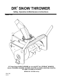
®
DR SNOW THROWER
Safety, Operation & Maintenance Instructions
Model: 8157
30" Single Stage SNOW THROWER for use with DR® ALL-TERRAIN™ MOWERS
Models: A2080BMA, A2080BEA, A2105BEA, A2125TEA, A2150KEA, A2090TMA, A2090TEA,
A2110BEA, A2130BEA & A2150KEA
SERIAL NO. 2015280 and up
OM 0308
10/02
TABLE OF CONTENTS
INTRODUCTION – TO THE PURCHASER..........................................................................................................4
SAFETY PRECAUTIONS.......................................................................................................................................5
Before Operation .................................................................................................................................................5
Notice...................................................................................................................................................................6
The DR® SNOW THROWER .............................................................................................................................6
Before Operation ............................................................................................................................................6
Operating the DR® SNOW THROWER ........................................................................................................7
Maintenance.........................................................................................................................................................8
Storage.................................................................................................................................................................8
DECALS...................................................................................................................................................................9
ASSEMBLY & INSTALLATION .........................................................................................................................10
Step 1: Preparation .......................................................................................................................................10
Step 2: Chute Installation .............................................................................................................................11
Step 3: Installation........................................................................................................................................12
Step 4: Belt Installation ................................................................................................................................12
Step 5: Rotation Handle Installation.............................................................................................................13
Step 6: Optional Drift Cutters Installation....................................................................................................14
Removing the DR® SNOW THROWER...........................................................................................................14
OPERATION..........................................................................................................................................................15
Operating Controls .......................................................................................................................................15
Adjustments..................................................................................................................................................15
General Preparation ......................................................................................................................................16
Increasing Traction & Stability ....................................................................................................................16
Engine Speed................................................................................................................................................16
Snow Removal..............................................................................................................................................16
Snow Removal Methods...............................................................................................................................17
MAINTENANCE ..............................................................................................................................................18
Drive Chain Replacement.............................................................................................................................18
Drive Belt Replacement ...............................................................................................................................18
Shear Bolt Replacement ...............................................................................................................................19
Lubrication ...................................................................................................................................................19
Storage..........................................................................................................................................................19
SPECIFICATIONS ...........................................................................................................................................20
PARTS ...................................................................................................................................................................21
Introduction.....................................................................................................................................................21
30" DR® SNOW THROWER - 8157..............................................................................................................22
Chute with Deflector.......................................................................................................................................24
Manual Chute Rotation System ......................................................................................................................25
Optional Drift Cutters - 8173 ..........................................................................................................................26
TORQUE SPECIFICATION TABLE....................................................................................................................27
DR® SNOW THROWER Safety, Operation & Maintenance Instructions
3
INTRODUCTION
To the Purchaser
Illustrations
This product is designed to give safe,
dependable service if it is operated and
maintained according to these instructions.
Read and understand this manual before
operation.
The illustrations may not necessarily reproduce
the full detail and the exact shape of the parts
or depict the actual models, and are intended
for reference only.
This manual has been prepared to assist the
owner/operators in the safe operation and
suitable maintenance of the DR® SNOW
THROWER. The information was applicable
to products at the time of manufacture and does
not include modifications made afterwards.
Direction Reference
All references to right and left, forward or
backward, are from the operator steering the
DR® ALL-TERRAIN™ MOWER.
Read and understand this operator's manual
before attempting to put a DR® SNOW
THROWER into service. Familiarize yourself
with the operating instructions and all the
safety recommendations contained in this
manual and those labeled on the DR® SNOW
THROWER and on the DR® ALL-TERRAIN™
MOWER. Follow the safety recommendations
and make sure that those with whom you work
follow them.
To assist our Customer Service Department in handling your needs, please record hereafter the model
number and serial number of your DR® SNOW THROWER and DR® ALL-TERRAIN™ MOWER. It
is also advisable to supply them to your insurance company. It will be helpful in the event that your
DR® SNOW THROWER or DR® ALL-TERRAIN™ MOWER is lost or stolen.
DR® ALL-TERRAIN™ MOWER
DR® SNOW THROWER
MODEL:
SERIAL NUMBER:
DATE OF PURCHASE:
DEALER NAME:
(If applicable)
4
DR® SNOW THROWER Safety, Operation & Maintenance Instructions
SAFETY PRECAUTIONS
SAFETY FIRST
This symbol, the industry's “Safety Alert Symbol” is used throughout this manual and on the
machine's labels to warn of the possibility of personal injury. Read these instructions
carefully. It is essential that you read the instructions and safety regulations before you
attempt to assemble or use this unit.
DANGER:
Indicates an immediately hazardous situation which, if not avoided, will
result in death or serious injury.
WARNING:
Indicates a potentially hazardous situation which, if not avoided, could
result in death or serious injury.
CAUTION:
Indicates a potentially hazardous situation which, if not avoided, may
result in minor or moderate injury.
Indicates that equipment or property damage could result if instructions
are not followed.
Gives helpful information.
IMPORTANT:
NOTE:
This product is designed to give safe, dependable service if it is operated and maintained according to
these instructions. Read and understand this manual before operation. It is the Owner's
responsibility to be certain anyone operating this product reads this manual, and all other applicable
manuals, to become familiar with this equipment and all safety precautions. Failure to do so could
result in serious personal injury or equipment damage.
Before Operation
Children
Tragic accidents can occur if the operator is not
alert to the presence of children. Children are
generally attracted to machines and the work
being done. Never assume children will remain
where you last saw them.
1. Keep children out of the operating area and
under the watchful eye of another
responsible adult.
2. Be alert and turn machine off if children
enter the work area.
4. Never allow children to play with the
machine or attachment even when they are
turned off.
5. Never allow children to operate the
machine even under adult supervision.
6. Use extra care when approaching blind
corners, shrubs, trees, or other obstructions
that might hide children from sight.
3. Before and when backing up the machine,
look behind for small children.
DR® SNOW THROWER Safety, Operation & Maintenance Instructions
5
SAFETY PRECAUTIONS
Notice…
A safe operator is the best assurance against accidents. All operators, no matter how experienced they
may be, should read this operator's manual and all other related manuals before attempting to operate a
DR® SNOW THROWER. Please read the following section and pay particular attention to all safety
recommendations contained in this manual and those labeled on the DR® SNOW THROWER and on
the DR® ALL-TERRAIN™ MOWER.
Before Operating the DR® SNOW THROWER
1. Read and understand this operator's manual
and the DR® ALL-TERRAIN™ MOWER
operator's manual. Know how to operate all
controls and how to stop the unit and
disengage the controls quickly.
2. Never wear loose, torn, or bulky clothing
around the DR® ALL-TERRAIN™ MOWER
and the DR® SNOW THROWER. It may
catch on moving parts or controls, leading to
the risk of accident.
3. Before using the equipment, thoroughly
inspect the area where the equipment is to be
used and remove all objects that may
damage the equipment.
4. Disengage the clutch and shift into neutral
before starting the engine.
5. Do not operate equipment in wintertime
without wearing adequate winter garments.
6
6. Never attempt to make any adjustments
while the engine is running. Read this
manual carefully to acquaint yourself with
the equipment as well as the DR® ALLTERRAIN™ MOWER Operator's Manual.
Working with unfamiliar equipment can lead
to accidents. Be thoroughly familiar with the
controls and proper use of the equipment.
7. Replace all missing, illegible, or damaged
safety and warning decals. See list of decals
in the Operator's Manual.
8. Do not modify or alter this equipment or any
of its components, or any equipment
function. Doing so will void your warranty.
9. Keep safety decals clean of dirt and grime.
10. Keep all shields in place and properly tighten
all mounting hardware.
DR® SNOW THROWER Safety, Operation & Maintenance Instructions
SAFETY PRECAUTIONS
Operating the DR® SNOW
THROWER
Never operate the DR® SNOW THROWER
without good visibility and lighting.
1. Do not make mechanical adjustments while
the unit is in motion, the DR® SNOW
THROWER is raised, or the engine is
running.
2. Do not put hands or feet near rotating parts.
Keep clear of discharge opening at all times.
Do not use hands or feet to unclog spout.
3. Never allow anyone to sit or stand on the
equipment at any time.
®
™
4. Before leaving the DR ALL-TERRAIN
MOWER unattended, take all necessary
precautions. Park the DR® ALL-TERRAIN™
MOWER on level ground, place the
transmission in neutral, set the parking
brake, disengage the driving system, place
all levers including auxiliary control levers
in neutral, shut off the engine and remove
the ignition key.
5. Exercise extreme caution when operating on
or crossing gravel driveways, walks, or
roads. Stay alert for hidden hazards or
traffic.
6. Do not run the engine indoors except when
starting engine and transporting attachment
in or out of building. Carbon monoxide gas
is colorless, odorless and deadly.
7. Do not attempt to operate on steep slopes or
near embankments.
9. Prolonged exposure to loud noise can cause
impairment or loss of hearing. Wear a
suitable hearing protection such as earmuffs
or earplugs to protect your valuable hearing.
10. Always wear eye protection during operation
(safety goggles, face shield, etc.).
11. Never allow anyone to operate the
equipment until they read the manual
completely and are thoroughly familiar with
basic DR® ALL-TERRAIN™ MOWER and
equipment operation.
12. Always make sure all equipment
components are properly installed and
securely fastened BEFORE operating.
13. Adjust collector-housing height to clear
gravel or crushed rock surface.
14. If the DR® SNOW THROWER starts to
vibrate abnormally, stop the engine
immediately, disconnect the spark plug wire
and check for cause. Excessive vibration is
generally a sign of trouble.
15. Never operate the DR® SNOW THROWER
without guards and other safety protective
devices in place.
16. Do not direct the discharge chute at
bystanders or animals. Ejected objects may
cause injury.
Read the separate DR® ALL-TERRAIN™
MOWER Operator's Manual carefully before
using the machine. Lack of operating
knowledge can lead to accidents.
8. Use extra caution when backing up.
DR® SNOW THROWER Safety, Operation & Maintenance Instructions
7
SAFETY PRECAUTIONS
Maintenance
Storage
ALWAYS USE GENUINE PARTS WHEN
REPLACEMENT PARTS ARE
REQUIRED
!
WARNING: Always disconnect the spark
plug wire before servicing your machine.
1. Park the DR® ALL-TERRAIN™ MOWER
on level ground, set the parking brake,
disengage the driving system, place all
levers including auxiliary control levers in
neutral, shut off the engine and remove the
spark plug wire BEFORE making any
adjustments.
2. Make sure all shields and guards are
securely in place following all service,
cleaning, or repair work.
3. To avoid injury, do not adjust, unclog or
service the equipment with the DR® ALLTERRAIN™ MOWER engine running.
Make sure rotating components have
completely stopped and the spark plug wire
is disconnected BEFORE making any
adjustments.
Before storing the equipment, certain
precautions should be taken to protect it from
deterioration:
!
WARNING: Always disconnect the spark
plug wire before servicing your machine.
1. Clean the equipment thoroughly.
2. Make all the necessary repairs.
3. Replace all Safety Decals that are damaged,
lost, or otherwise become illegible. If a part
to be replaced has a decal on it, obtain a
new safety decal and install it in the same
place as on the removed part.
4. Repaint all parts from which paint has worn
or peeled.
5. When the DR® SNOW THROWER is dry,
lubricate all moving parts. Apply Fluid
Film® or comparable lubricant liberally to
all surfaces to protect against rust.
6. Store in a dry place.
4. Keep the DR® ALL-TERRAIN™ MOWER/
equipment clean. Build-up of debris can
lead to malfunction or serious personal
injury.
5. Always wear eye protection when cleaning
or servicing the equipment.
6. Do not modify or alter this equipment or
any of its components or operating
functions.
7. Change the oil to an appropriate grade for
winter use. Consult your engine
manufacturer's owner's manual.
8
DR® SNOW THROWER Safety, Operation & Maintenance Instructions
DECALS
Replace Immediately if Damaged
(See Parts section for decal location)
657762
660988
660263
660265
DR® SNOW THROWER Safety, Operation & Maintenance Instructions
657761
9
ASSEMBLY & INSTALLATION
Step 1: Preparation (Figure 1)
After opening the crate and removing all the
cardboard, remove the box containing the chute
and the instructions (item 2).
1. Remove the two screws (item 4) that retain
the housing (item 1) on the pallet (item 3).
2. Verify that you have all components on the
following list:
If anything is missing, please call one of our
Customer Service Representatives TOLL-FREE
1(800)DR-OWNER(376-9637).
Crate
Qty
1
1
1
1
1
Item
DR® SNOW THROWER assembly
Chute assembly
Rotation handle
Worm shaft
Bag
1
3
1
2
6
6
1
1
1
1
1
1
Bag
Handle support
Retaining plates
U bolt 1/4" NC x 1 1/8" x 2", PTD
Plastic bushings
Hex. bolts 1/4" NC x 1/2", PTD
Flange nuts 1/4" NC, PTD
Flatwasher 41/64" I.D.
Hairpin 2mm x 41mm, PTD
Cotter pin 1/8" x 1 3/4", PTD
Operator's Manual
Packing list
Spare shear bolt
Figure 1
10
DR® SNOW THROWER Safety, Operation & Maintenance Instructions
ASSEMBLY & INSTALLATION
Step 2: Chute Installation (Figure 2)
For assembly, place the DR ® SNOW
THROWER on a flat and level surface.
1. Place the chute (item 1) on the discharge
hole (item 2) around the DR® SNOW
THROWER.
2. Install the three retaining plates (item 3)
using the six 1/4" x 1/2" bolts and flange
nuts (items 4-5), tighten securely. Verify that
the chute turns freely on the collar.
Figure 2
DR® SNOW THROWER Safety, Operation & Maintenance Instructions
11
ASSEMBLY & INSTALLATION
!
WARNING: Before installing the DR®
SNOW THROWER, always bring the DR® ALLTERRAIN™ MOWER to a complete stop, shut
off the engine and remove the spark plug wire.
Step 3: Installation (Figure 3)
1. Remove the mowing deck from the DR®
ALL-TERRAIN™ MOWER.
2. Apply grease on the shaft (item 6).
3. Remove bolts (item 5) from belt cover.
Step 4: Belt Installation (Figures 3 & 4)
1. Carefully install the drive belt (item 1)
around the drive pulley (item 2) under the
DR® ALL-TERRAIN™ MOWER.
2. Pull the tensioner (item 3) to reinstall the
belt on the idler. Make sure that the V-belt is
not twisted and fits correctly in the V-groove
on the pulley.
3. Make sure to position the belt above the belt
guide, as shown in figure 4.
4. Reinstall the belt cover (item 4) and bolts.
4. Remove the belt cover (item 4).
5. Align the DR® ALL-TERRAIN™ MOWER
and DR® SNOW THROWER. Carefully,
insert the shaft (item 6) of the ALLTERRAIN™ MOWER into the female
attachment on the SNOW THROWER.
Figure 4
6. Reinstall the collar and pin used with the
mower to secure the SNOW THROWER.
Figure 3
12
DR® SNOW THROWER Safety, Operation & Maintenance Instructions
ASSEMBLY & INSTALLATION
Step 5: Rotation Handle Installation
(Figure 5)
1. On the left side handlebar of the DR® ALLTERRAIN™ MOWER, install the rotation
handle support (item 1) at approximately 28"
from the ground, using the U-bolt (item 2),
plate and nuts.
! WARNING: Make sure the chute blocks
in both directions to prevent the snow from
being projected in the operator's area
(Figure 6).
Figure 6
2. Insert the plastic bushing (item 3, flange
facing the operator) on the housing by
pushing forward until it snaps.
3. Insert the worm shaft (item 4) in the plastic
bushing.
4. Place the flat washer (item 5) and lock the
shaft in place with the cotter pin (item 6).
5. Insert the plastic bushing (item 3, flange
facing the operator) into the rotation handle
support (item 1).
6. Insert the rotation handle (item 7) through
the support then in the worm shaft (item 4).
Secure with the hairpin (item 8).
7. Operate the handle and check for proper
operation of the chute.
Figure 5
DR® SNOW THROWER Safety, Operation & Maintenance Instructions
13
ASSEMBLY & INSTALLATION
Step 6: Optional Drift Cutters - 8173
Installation (Figure 7)
1. From the exterior of the housing, align the
two square holes on the drift cutter (item 1)
with the two round holes on the housing.
2. From the outside, insert the 5/16" x 5/8"
carriage bolts (item 2).
3. Secure with two flange nuts (item 3).
4. Repeat on the other side.
Removing the DR® Snow Thrower
1. Select a level surface, turn engine off and
remove ignition key
2. Refer to Figure 5, Page 13. Remove hairpin
(item 8) and rotation handle (item 7).
3. Refer to Figure 4, Page 12. Remove the belt
cover (item 4).
4. Refer to Figure 3, Page 12. Pull the
tensioner (item 3) to remove the drive belt
(item 1).
5. Refer to Figure 3, Page 12. Unlock the pin
(item 6) and carefully remove the DR® ALLTERRAIN™ MOWER from the DR® SNOW
THROWER.
Figure 7
14
DR® SNOW THROWER Safety, Operation & Maintenance Instructions
OPERATION
Operating Controls
Adjustments
The DR® SNOW THROWER is driven from the
DR® ALL-TERRAIN™ MOWER drive pulley.
Deflector Adjustment
WARNING:
1. Do not allow bystanders near working area.
Adjust the deflector angle according to the
distance the snow must be thrown. To adjust,
loosen the knob, adjust to the desired angle then
tighten knob securely.
2. Do not allow anyone to ride on the DR®
SNOW THROWER.
Skid Shoe Adjustment (Figures 8 & 9)
!
3. Before cleaning, adjusting or repairing the
DR® SNOW THROWER: bring the DR® ALLTERRAIN™ MOWER to a complete stop, wait
for all movement to stop, apply the parking
brake, shut off the engine and remove the
spark plug wire.
4. Never put any part of your body under the
DR® SNOW THROWER while making
adjustments.
Adjust skid shoes in order to allow the required
clearance (H) between the cutting edge and the
surface, by loosening the 5/16" x 5/8" carriage
bolts (item 2).
On level paved surface or asphalt roadway:
leave 1/16" to 1/8" clearance (H).
On uneven or gravel surface, depending on
gravel size: leave 1/2" to 5/8" clearance (H).
Chute Rotation
Adjust the chute direction with the rotation
handle.
!
WARNING: Always keep the DR® SNOW
THROWER discharge away from people,
animals and objects which could be struck by
debris.
Figure 9
Figure 8
DR® SNOW THROWER Safety, Operation & Maintenance Instructions
15
OPERATION
General Preparation
Snow Removal
1. Use a winter grade oil in your DR® ALLTERRAIN™ MOWER. See the engine
manufacturer's owner's manual.
Never use the DR® SNOW THROWER as a
snowplow. Do not push the snow, let the
SNOW THROWER work its way through deep
drifts. For best results, raise the SNOW
THROWER and remove a top layer of snow.
A second pass will remove the remaining
snow.
2. Make sure that the auger operates freely.
3. Adjust the skid shoes so that the DR®
SNOW THROWER runs level.
4. Make sure that the DR® SNOW
THROWER is clear of snow before
engaging the drive belt.
!
If ground speed is too fast, the DR® SNOW
THROWER may become overloaded and may
clog. Maintain a ground speed suited for the
job to be done.
WARNING:
1. Read this Operator's Manual carefully. Be
thoroughly familiar with the controls and
proper use of the equipment. Know how to
stop the unit and disengage the controls
quickly.
In heavy snow, take on only enough snow to
work easily. Engage and disengage the clutch
lever to reduce the ground speed to a level that
will allow the engine to keep its full revolution.
2. Never allow children to operate equipment.
Never allow adults to operate equipment
without proper instruction.
NOTE: Use full RPM power when removing
wet, sticky snow. Low RPM power will tend to
clog the chute.
3. Keep the area of operation clear of people,
animals and debris.
4. Clothing worn by the operator should be
fairly tight and belted. Loose clothing
should not be permitted because of the
danger of getting into moving parts.
Increasing Traction and Stability
Use DR® Tire Chains for extra traction and
stability. Call 1(800)DR-OWNER(376-9637)
to order.
!
WARNING: Do not use your hands to
unclog the chute. Use a short stick or board.
Never attempt to clear clogged chute while the
DR® ALL-TERRAIN™ MOWER engine is
running. If the chute clogs, disengage the
drive belt, wait for all movement to stop, apply
the parking brake, shut off the engine and
remove the spark plug wire before unclogging.
NOTE: Run the DR® SNOW THROWER a
few minutes after blowing snow to prevent
freeze up of auger.
Engine Speed
!
CAUTION: Use only moderate engine
speed when engaging the drive belt.
Engaging the belt at high speed will shorten
the clutch life.
For maximum power, operate the engine at, or
near, full throttle.
16
DR® SNOW THROWER Safety, Operation & Maintenance Instructions
OPERATION
Snow Removal Methods
When removing snow, do not use the DR® SNOW THROWER as a dozer blade to push snow. Let the
DR® SNOW THROWER work its way through deep drifts. If the speed of your DR® ALL-TERRAIN™
MOWER is too fast, the DR® SNOW THROWER may become overloaded and clog. For best results,
raise the DR® SNOW THROWER and remove the top layers of snow, or take a half-width pass. A
second pass with the DR® SNOW THROWER will remove the remaining snow.
IMPORTANT: Use full RPM power when removing wet, sticky snow. Low RPM power will tend to
clog the chute.
NOTE: In heavy snow, engage and disengage the clutch lever to reduce the ground speed to a level
that will allow the engine to keep its full revolution.
! WARNING! To avoid serious personal injury, do not use hands or feet to unclog chute.
Do not attempt to clear clogged chute of snow while DR® ALL-TERRAIN™ MOWER engine is
running. If the chute clogs, disengage the drive shaft, shut off the engine, remove the spark
plug wire and wait for all movement to stop, and then clear the snow from the chute.
A definite pattern of operation is required to thoroughly clean an area of snow. These patterns will
avoid throwing snow in unwanted places as well as eliminating a second removal of snow.
Where it is possible to throw the snow to the
left and right (above), as on a long driveway, it
is advantageous to start in the middle. Plow
from one end to the other, throwing snow to
both sides without changing the direction of the
discharge chute.
If the snow can only be thrown to one side of
the driveway or sidewalk (above), start on the
opposite side. At the end of the first pass,
rotate the discharge chute 180 degrees for the
return pass. At the end of each succeeding
pass, rotate the discharge guide 180 degrees to
maintain direction of throw in the same area.
DR® SNOW THROWER Safety, Operation & Maintenance Instructions
17
MAINTENANCE
ALWAYS USE GENUINE PARTS WHEN
REPLACEMENT PARTS ARE REQUIRED
!
WARNING: Never park the DR® ALLTERRAIN™ MOWER with fuel in the fuel tank
inside a building where an open flame or
sparks are present. Allow the engine to cool
down before storing in any enclosure.
Drive Belt Replacement (Figure 4,
Page 12)
When the belt tensioner is 1/8" close to its
support (see figure below) due to belt
elongation or after the equivalent of 60 hours of
continuous operation, replace the drive belt.
!
!
WARNING: Provide adequate blocking
before working under the DR® SNOW
THROWER.
!
WARNING: Run the DR® SNOW
THROWER a few minutes after throwing snow
to prevent freeze up of auger.
Drive Chain Replacement (Figure 10)
Replace the chain when the distance between
the sections of the chain (item 1) is reduced to
2" (see figure).
!
WARNING: Always disconnect the spark
plug wire before servicing your machine.
1. Remove the bolts (item 5) to remove the
belt cover (item 4).
2. Pull the tensioner (item 3) and remove the
belt (item 1) from the pulleys.
3. Install the new belt in the same pathway as
the old one.
4. Re-engage the tensioner.
5. Reinstall the belt cover with the bolts.
WARNING: Always disconnect the spark
plug wire before servicing your machine.
1. Unbolt the chain cover (item 2) and remove
it.
2. Remove the connecting link on the chain,
and remove the chain.
3. Check the chain tensioner (item 5) for wear.
Replace if necessary.
4. Install the new chain around the sprockets
(items 3 & 4).
5. Pull the tensioner (item 5) and install the
connecting link on the new chain.
6. Release the tensioner on the chain.
7. Lubricate the new chain with chain saw
lubricant.
8. Reinstall the cover.
Figure 10
18
DR® SNOW THROWER Safety, Operation & Maintenance Instructions
MAINTENANCE
Shear Bolt Replacement (Figure 11)
If you strike a foreign object (wood, stone, etc.)
there is a safety shear bolt on the driving
system. This shear bolt will break, eliminating
any driving force to the auger.
!
WARNING: Always disconnect the spark
plug wire before servicing your machine.
1. To replace the shear bolt, stop the DR®
ALL-TERRAIN™ MOWER and remove the
spark plug wire.
2. Remove the bolts (item 1), and remove the
belt cover (item 2).
3. Make sure that there is no debris remaining
in the shaft hole.
4. Align the pulley hole with the shaft hole
(item 3) and install the new shear bolt and
nut (item 4). Tighten securely.
5. Reinstall cover and bolts.
Lubrication
!
WARNING: Always disconnect the spark
plug wire before servicing your machine.
Lubricate the drive chain with chain saw chain
lubricant every 2 hours of operation and also
after each use.
Storage
Before storing the DR® SNOW THROWER,
certain precautions should be taken to protect it
from deterioration.
!
WARNING: Always disconnect the spark
plug wire before servicing your machine.
1. Clean the DR® SNOW THROWER
thoroughly.
2. Make all the necessary repairs.
3. Repaint all parts from which paint has worn
or peeled.
4. Lubricate the DR® SNOW THROWER as
instructed under Lubrication.
5. When the DR® SNOW THROWER is dry,
lubricate all moving parts. Apply Fluid
Film® or comparable lubricant liberally to
all surfaces to protect against rust.
6. Store in a dry place.
Figure 11
DR® SNOW THROWER Safety, Operation & Maintenance Instructions
19
SPECIFICATIONS
Country Home Products Single Stage DR® SNOW THROWER
Overall width
Overall height (without chute)
Overall height (with chute)
Overall length
Cutting width
Cutting height
Frame thickness
Side thickness
Number of stages
Drive
Drive pulley
Idler belt adjustment
Auger drive
Ratio
Auger RPM
Idler chain adjustment
Auger diameter
Auger pitch
Chute position
Chute rotation
Adjustable deflector
Adjustable skid shoes
Replaceable cutting edge
Number of shear bolts on drive pulley
Optional Drift cutters
Hitch system
Weight with chute
20
30 1/2"
19 1/2"
37 1/2"
29 1/8"
29 3/4"
18 1/4"
16 Ga.
12 Ga.
1
'B'' type belt and ''B'' type pulley
5 3/4" O.D.
Automatic spring tensioner
# 40 chain and sprockets
2,82:1
1260 RPM
Automatic spring tensioner
11 3/4"
11 1/4"
Center
Manual
Yes
Yes
Yes
1
Optional
Fixed to Walk behind (cylindrical pin)
126 lbs
DR® SNOW THROWER Safety, Operation & Maintenance Instructions
PARTS
Introduction
All parts are illustrated in “exploded views” which show the individual parts in their normal
relationship to each other. Reference numbers are used in the illustrations. These numbers correspond
to those in the “Reference Number” (REF) column, and are followed by the description and quantity
required.
O/L - “Obtain Locally” in the part number column indicates common hardware that is available at your
local hardware supply.
All reference to right and left, forward or rearward, are from the operator steering the DR® ALLTERRAIN™ MOWER.
The manufacturer reserves the rights to change, modify, or eliminate from time to time, for technical
or other reasons, certain or all data, specifications, or the product or products themselves, without any
liability or obligation.
DR® SNOW THROWER Safety, Operation & Maintenance Instructions
21
PARTS
30" DR® SNOW THROWER - 8157
22
DR® SNOW THROWER Safety, Operation & Maintenance Instruction
PARTS
30" DR® SNOW THROWER - 8157
REF
1
2
3
4
5
6
7
8
9
10
11
12
13
14
15
16
17
18
19
20
21
22
23
24
25
26
27
28
29
30
31
32
33
34
DESCRIPTION
Frame
Cutting edge
Auger
Driving shaft
Protective shield
Chain guard
Belt cover
Skid shoes
Belt tensioner
Bearing flange
Pulley 5 3/4" dia.
Pulley 4 1/4" dia.
Pulley 4 15/16" dia.
Bearing dia. 1"
Bearing dia. 3/4"
Flange
Chain #40
Connecting link
Chain tensioner
Torsion spring
Tensioner spring
V belt B78 5/8" x 81"
Hex. bolt 3/8" NC x 1 3/4" lg Gr.5
Carriage bolt 5/16" NC x 5/8" Gr.5
Serrated flange bolt 5/16" NC x 1/2" Gr.5
Shear bolt incl. nut
Serrated flange nut 3/8" NC, PTD
Serrated flange nut 5/16"NC
Decal "Lubrication"
Cotter pin 3/16" x 2" lg
Cotter pin 1/8" x 1 3/4" lg
Decal "Danger"
Decal "SNOW THROWER"
Decal "Danger"
Decal "Serial number"
QTY
1
1
1
1
1
1
1
2
1
2
1
1
1
2
2
4
1
1
1
1
1
1
2
12
12
1
2
12
1
1
2
1
1
1
1
PART #
665939
665727
665718
665719
665742
665723
665725
665677
665716
665743
4800002
4800003
4800004
665494
4300011
4300012
3300004
659721
665960
3800016
659087
4800001
O/L
O/L
O/L
660894
O/L
O/L
660263
O/L
O/L
657762
2500325
660265
2500322
O/L = Obtain Locally
DR® SNOW THROWER Safety, Operation & Maintenance Instructions
23
PARTS
Chute with deflector
REF
1
2
3
4
5
6
7
8
9
10
11
12
13
14
15
DESCRIPTION
Chute ass'y
Chute base
Deflector
Retaining plate
Plastic ring
Knob
Nylon washer dia. 7/16"
Carriage bolt 5/16" NC x 5/8"
Machine screw 10-32 NC x 5/8"
Nylon insert locknut 5/16" NC
Nylon insert locknut 5mm x 0.8
Decal "Warning"
Decal "Danger"
Hex. bolt 1/4" NC x 1/2" NC Gr.5
Serrated flange nut 1/4" NC
Flatwasher 1/4"
QTY
1
1
1
3
1
1
3
3
3
2
3
1
1
6
6
3
PART #
665736
665737
665738
657333
665948
657309
658468
O/L
2700008
O/L
1000020
660988
657761
O/L
O/L
O/L
O/L = Obtain Locally
24
DR® SNOW THROWER Safety, Operation & Maintenance Instructions
PARTS
Manual chute rotation system
REF
1
2
3
4
5
6
7
8
DESCRIPTION
Rotation handle
Worm shaft
Plastic bushing
Handle support
Flat washer 41/64"
Cotter pin 1/8" x 1 3/4"
Hairpin 1/16" x 1 5/8"
U bolt 1/4" NC x 1 1/8", including nuts and plate
QTY
1
1
2
1
1
1
1
1
PART #
665733
665734
665959
665726
O/L
O/L
O/L
0400020
O/L = Obtain Locally
DR® SNOW THROWER Safety, Operation & Maintenance Instructions
25
PARTS
Optional Drift Cutters - 8173
REF
1
2
3
DESCRIPTION
Flange nut 5/16" NC
Drift cutters
Carriage bolt 5/16" NC x 5/8" Gr.5
QTY
4
2
4
PART #
O/L
665746
O/L
O/L = Obtain Locally
26
DR® SNOW THROWER Safety, Operation & Maintenance Instructions
TORQUE SPECIFICATION TABLE
GENERAL SPECIFICATION TABLE
Use the following torques when special torques are not given
NOTE: These values apply to fasteners as received from supplier, dry, or when lubricated with normal engine oil. They do not apply if special
graphited or moly sidulphide greases or other extreme pressure lubricants are used. This applies to both UNF and UNC threads.
SEE Grade No.
2
5
8
BOLT HEAD
IDENTIFICATION MARKS
AS PER GRADE
NOTE: MANUFACTURING
MARKS WILL VARY.
Torque
Torque
Torque
BOLT SIZES
Pounds-Foot
Newtons-Meter
Pounds-Foot
Newtons-Meter
Pounds-Foot
Newtons-Meter
Inches
Millimeters
MIN.
MAX.
MIN.
MAX.
MIN.
MAX.
MIN.
MAX.
MIN.
MAX.
MIN.
MAX.
1/4
6.35
5
6
6.8
8.13
9
11.0
12.2
14.9
12
15
16.3
30.3
5/16
7.94
10
12
13.6
16.3
17
20.5
23.1
27.8
24
29
32.5
39.3
3/8
9.53
20
23
27.1
31.2
35
42.0
47.5
57.0
45
54
61.0
73.2
7/16
11.11
25
30
40.7
47.4
54
64.0
73.2
86.8
70
84
94.9
113.9
1/2
12.70
45
52
61.0
70.5
80
96.0
108.5
130.2
110
132
149.2
179.0
9/16
14.29
65
75
88.1
101.6
110
132.0
149.2
179.0
160
192
217.0
260.4
5/8
15.88
95
105
128.7
142.3
150
180
203.4
244.1
220
264
298.3
358.0
3/4
19.05
150
185
203.3
250.7
270
324
366.1
439.3
380
456
515.3
618.3
7/8
22.23
160
200
216.8
271.0
400
480
542.4
650.9
600
720
813.6
976.3
1
25.40
250
300
338.8
406.5
580
696
786.5
943.8
900
1080 1220.4
1464.5
1 1/8
25.58
800
880
1084.8 1193.3 1280
1440 1735.7
1952.6
1 1/4
31.75
1120
1240 1518.7 1681.4 1820
2000 2467.9
2712.0
1 3/8
34.93
1460
1680 1979.8 2278.1 2380
2720 3227.3
3688.3
1 1/2
38.10
1940
2200 2630.6 2983.2 3160
3560 4285.0
4827.4
METRIC BOLT TORQUE SPECIFICATIONS
Size of
Grade No.
screw
M6
M8
M10
M12
M14
M16
M18
M20
4T
7T
8T
4T
7T
8T
4T
7T
8T
4T
7T
8T
4T
7T
8T
4T
7T
8T
4T
7T
8T
4T
7T
8T
Pitch
(mm)
1.0
1.25
1.5
1.75
2.0
2.0
2.0
2.5
Coarse thread
Pounds-Foot
MIN.
MAX.
3.6
5.8
5.8
9.4
7.2
10
7.2
17
20
20
34
38
28
51
57
49
81
96
67
116
129
88
150
175
108
186
213
14
22
26
25
40
46
34
59
66
56
93
109
77
130
145
100
168
194
130
205
249
Newtons-Meter
MIN.
MAX.
4.9
7.9
7.9
12.7
9.8
13.6
9.8
19.0
23
29.8
27.1
35.2
27.1
33.9
46.1
54.2
51.5
62.3
37.9
46.1
69.1
79.9
77.2
89.4
66.4
75.9
109.8
126
130.1
147.7
90.8
104.3
157.2
176.2
174.8
196.5
119.2
136
203.3
227.6
237.1
262.9
146.3
176.2
252
277.8
288.6
337.4
Pitch
(mm)
-
1.0
1.25
1.25
1.5
1.5
1.5
1.5
DR® SNOW THROWER Safety, Operation & Maintenance Instructions
Fine Thread
Pounds-Foot
Newtons-Meter
MIN.
MAX.
MIN.
MAX.
12
19
22
20
35
40
31
56
62
52
90
107
69
120
140
100
177
202
132
206
246
17
27
31
29
47
52
41
68
75
64
106
124
83
138
158
117
199
231
150
242
289
16.3
25.7
29.8
27.1
47.4
54.2
42
75.9
84
70.5
122
145
93.5
162.6
189.7
136
239.8
273.7
178.9
279.1
333.3
23.0
36.6
42
39.3
63.7
70.5
55.6
92.1
101.6
86.7
143.6
168
112.5
187
214.1
158.5
269.6
313
203.3
327.9
391.6
27
WARRANTY
The DR® SNOW THROWER is warranted for one (1) year against defects in materials or
workmanship when put to ordinary and normal consumer use (ninety (90) days for any other use).
The Limited 1-Year Warranty on the DR® SNOW THROWER starts from the original ship date of the
machine. The Limited 1-Year Warranty is applicable only to the original owner.
The owner is responsible for the performance of the required maintenance as defined by the
manufacturer's owner's manual. The owner is responsible for replacement of wearable items such as
shear bolts, skid shoes, cutting edge, bearings, chain, and belt, that are not covered under this warranty.
Country Home Products, Inc. certifies that the DR® SNOW THROWER is fit for ordinary purposes for
which a product of this type is used. Country Home Products, Inc. however, limits the implied
warranties of merchantability and fitness in duration to a period of one (1) year in consumer use,
ninety (90) days in any other use.
SOME STATES DO NOT ALLOW LIMITATIONS ON THE LENGTH OF IMPLIED WARRANTIES, SO THE ABOVE
LIMITATIONS MAY NOT APPLY TO YOU.
FOR WARRANTY SERVICE
Contact Country Home Products, Inc., which reserves the right to examine the machine and make its
own evaluation at its option.
CUSTOMER SERVICE HOTLINE
Country Home Products, Inc.’s objective is to have 100% satisfied customers. For that reason, we
operate a 7-day-a-week Customer Service Department for our Owners. You can access a
Representative by dialing our TOLL-FREE Hotline at 1(800)DR-OWNER (376-9637). The sole
job of our well-trained and friendly folks is to ensure that you get any help you need in a timely
fashion. They are there to answer all your questions including (1) inquiries on any of the above
warranties, (2) inquiries about replacement parts, or (3) your questions regarding service, maintenance
and operation.
THIS WARRANTY GIVES YOU SPECIFIC LEGAL RIGHTS, AND YOU ALSO HAVE OTHER
RIGHTS, WHICH VARY FROM STATE TO STATE.
COUNTRY HOME PRODUCTS®
Meigs Road, P.O. Box 25, Vergennes, Vermont 05491
TOLL-FREE 1(800)DR-OWNER(376-9637) • www.dr-owner.com
©2001 CHP, Inc. 157581
Printed in Canada