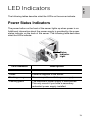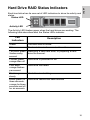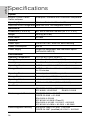
1
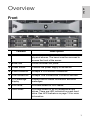
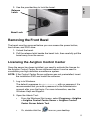
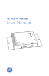
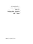
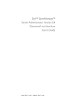
Installation Guide
Avigilon High Definition Network Video Recorder Server:
3.0TB-HD-NVR2, 5.0TB-HD-NVR2, 10.0TB-HD-NVR2,
15.0TB-HD-NVR2 and 21.0TB-HD-NVR2
920-0047B-Rev2
Copyright © 2012 Avigilon. All rights reserved.
No copying, distribution, publication, modification, or incorporation of this
document, in whole or part, is permitted without the express written
permission of Avigilon. In the event of any permitted copying, distribution,
publication, modification, or incorporation of this document, no changes in
or deletion of author attribution, trademark legend, or copyright notice
shall be made. No part of this document may be reproduced, stored in a
retrieval system, published, used for commercial exploitation, or
transmitted, in any form by any means, electronic, mechanical,
photocopying, recording, or otherwise, without the express written
permission of Avigilon.
Dell, PowerEdge R520, OpenManage Server Administrator and their
images are registered trademarks of Dell.
Microsoft and Windows are registered trademarks of Microsoft
Corporation.
Avigilon has made every effort to identify trademarked properties and
owners on this page. All brands and product names used in this
document are for identification purposes only and may be trademarks or
registered trademarks of their respective companies.
Avigilon
Tel +1.604.629.5182
Fax +1.604.629.5183
http://www.avigilon.com
Revised 07/11/2012
English
Table of Contents
Overview . . . . . . . . . . . . . . . . . . . . . . . . . . . . . . . . . . . 1
Front . . . . . . . . . . . . . . . . . . . . . . . . . . . . . . . . . . . . . . . . . 1
Back . . . . . . . . . . . . . . . . . . . . . . . . . . . . . . . . . . . . . . . . . 2
Installation . . . . . . . . . . . . . . . . . . . . . . . . . . . . . . . . . . 3
Required Tools and Materials . . . . . . . . . . . . . . . . . . . . . .
Package Contents . . . . . . . . . . . . . . . . . . . . . . . . . . . . . . .
Installation Steps . . . . . . . . . . . . . . . . . . . . . . . . . . . . . . . .
Installing the Rack Rails
and Cable Management Arm . . . . . . . . . . . . . . .
Connecting Cables . . . . . . . . . . . . . . . . . . . . . . .
Installing the Bezel . . . . . . . . . . . . . . . . . . . . . . .
Licensing the Avigilon Control Center . . . . . . . . .
Assigning an IP Address . . . . . . . . . . . . . . . . . . .
3
3
3
4
4
4
5
7
Advanced Features . . . . . . . . . . . . . . . . . . . . . . . . . . . 8
Server Administrator . . . . . . . . . . . . . . . . . . . . . . . . . . . . . 8
Connecting Storage Expansions . . . . . . . . . . . . . . . . . . . . 9
Replacing Hard Drives . . . . . . . . . . . . . . . . . . . . . . . . . . 10
LED Indicators . . . . . . . . . . . . . . . . . . . . . . . . . . . . . . 13
Power Status Indicators . . . . . . . . . . . . . . . . . . . . . . . . . 13
Network Link Status Indicator . . . . . . . . . . . . . . . . . . . . . 14
Hard Drive RAID Status Indicators . . . . . . . . . . . . . . . . . 15
Specifications . . . . . . . . . . . . . . . . . . . . . . . . . . . . . . 16
Limited Warranty & Technical Support . . . . . . . . . . 17
English
English
Overview
Front
Feature
Description
0 Bezel
The bezel protects the server from unauthorized
physical access. The bezel must be removed to
access the front of the server.
1 Bezel lock
Locks the bezel into place.
2 Power button
Controls the power supply to the server.
3 Video connector
Accepts a VGA monitor connection.
4 USB connectors
Accepts USB connections to external devices.
5 LCD message
Displays server status information and error
messages.
display
6 DVD drive
Provides access to DVD media.
7 Hard drives
Provides access to six hot-swappable hard
drives. There are LED indicators on each hard
drive. See LED Indicators on page 13 for more
information.
1
English
Back
Feature
Description
1 Power supply
Accepts power input.
In the image, the secondary redundant power
supply (HD-NVR2-2ND-PS) is installed.
2 Serial connector
Accepts connections to serial devices.
3 Video connector
Accepts a VGA monitor connection.
4 Expansion slots
There are 3 empty expansion slots.
This is where you would install the expansion
card (HD-NVR2-EXP2-CARD) for connecting to
storage expansions.
5 Ethernet port
Accepts an Ethernet connection to a network.
6 USB connectors
Accepts USB connections to external devices.
2
English
Installation
Required Tools and Materials
•
#1 Phillips screwdriver
Package Contents
Ensure the package contains the following:
•
Avigilon High Definition Network Video Recorder (NVR) Server
•
Avigilon Control Center Software Installation DVD
•
Avigilon Control Center Recovery DVD
•
Power Cable
•
USB Keyboard
•
USB Mouse
•
Bezel and Key
•
Rack Sliding Rail Assembly Kit
•
Cable Management Arm Assembly Kit
Installation Steps
Consult the Product Information Guide provided with the server for
relevant safety information before you begin installation.
•
Installing the Rack Rails and Cable Management Arm on page 4
•
Connecting Cables on page 4
•
Installing the Bezel on page 4
•
Licensing the Avigilon Control Center on page 5
•
Assigning an IP Address on page 7
3
English
Installing the Rack Rails and Cable Management
Arm
If the server will be kept in a server rack, install the Rack Sliding Rails and
the Cable Management Arm provided in the server package. Follow the
procedures outlined in the Rack Installation Instructions and the CMA
Installation Instructions provided in the assembly kits.
NOTE: The supplied Rack Sliding Rails are compatible with square and
round hole racks.
Connecting Cables
Refer to the server diagrams in the Overview section for the location of
the different connectors.
1. Connect the keyboard and mouse to an available USB connector
on either the front or the back of the server.
2. Connect a monitor to the video connector on the server.
3. Connect the server to your network using an Ethernet network
cable.
4. Connect the power cable to the power supply at the back of the
server.
5. If you are also installing an Avigilon HD NVR Storage Expansion
with your server, connect the server to the storage expansion.
See Connecting Storage Expansions on page 9 for more
information.
6. Press the power button on the front of the server. Check that the
server LED indicators display the correct status. See LED
Indicators on page 13 for more information.
Installing the Bezel
The bezel can be installed on the front of the server to help protect the
power button and hard drives against unauthorized access.
1. Slide the right end of the bezel against the right hinge of the
server.
2. Push the left end of the bezel against the server until it clicks into
place.
4
English
3. Use the provided key to lock the bezel.
Release
Latch
Bezel Lock
Removing the Front Bezel
The bezel must be removed before you can access the power button,
hard drives, and DVD drive.
1. Unlock the bezel.
2. Pull the release latch beside the bezel lock, then carefully pull the
bezel away from the server.
Licensing the Avigilon Control Center
Once the server has been installed, you need to activate the license for
the Avigilon Control Center Server software before it can be used to
coordinate your high definition surveillance system.
NOTE: If the Control Center Server software was not preinstalled, insert
the installation DVD and install the software.
1. Log in to Windows.
The default username is Administrator with no password. It is
recommended that you add a password to the Administrator
account after your first login. For more information, see the
Windows Help and Support.
2. Open the Admin Tool:
•
From the Windows Start menu, select Programs > Avigilon
> Avigilon Control Center Server > Avigilon Control
Center Server Admin Tool.
•
Or, double-click the
icon on your desktop.
5
English
3. When the Avigilon Control Center Admin Tool opens, select the
Settings tab and click Licensing.
4. In the License Activation dialog box, click Add License. The Add
License wizard is displayed.
You have two license activation options: Internet Activation or
Manual Activation. Complete one of the following procedures.
Internet Activation
If you have internet access on your server, the Admin Tool connects to the
internet and activates your license.
1. In the Add License wizard, click Internet Activation.
2. On the Enter Product Key page, enter your license key.
A green check mark will appear beside your license key when it is
correct.
3. Click Next.
4. On the Product Registration page, enter your contact information
to receive product updates. Then click Next.
5. The Admin Tool connects to the Avigilon licensing server and
activates the license.
When the Activation Succeeded message appears, click Finish.
Manual Activation
If your server does not have internet access, you can activate your license
by generating an activation file from the Admin Tool and uploading the file
to the Avigilon License Activation web page from a computer with internet
access.
1. In the Add License wizard, click Manual Activation.
2. On the following page, click Step 1: Generate Activation File.
3. On the Enter Product Key page, enter your license key.
A green check mark will appear beside your license key when it is
correct.
4. Click Next.
5. On the Select Activation File page, confirm where the activation
file will be saved. Click [...] to navigate to a different file location.
You can rename the activation file, but you must keep the .key
extension.
6
On the following page, you will see the Activation File Saved
message.
7. Find the saved activation file and copy the file to a computer with
internet access.
8. Open a web browser and go to http://activate.avigilon.com.
9. At the Avigilon License Activation web page, click Browse to
locate your activation file then click Upload Activation File.
10.When you see the You have successfully activated your product!
message, click Download License File and save the license file.
11.Complete the product registration section to receive product
updates from Avigilon, then click Register.
12.Find the downloaded license file and copy the file to the server
you are activating.
13.If the Activation File Saved message is still displayed in the Add
License wizard, click Next.
14.On the following page, click Step 2: Add License File.
15.On the Import License File page, click [...] to locate the license
file then click Next.
16.When the Activation Succeeded message appears, click Finish.
Assigning an IP Address
Once the Avigilon Control Center Server has been licensed, you can
assign an IP address to the server. The server obtains an IP address
automatically by default, but you can configure the server to use a static
IP address.
1. In Windows, select Start > Control Panel > Network
Connections.
2. Right-click a network connection and select Properties.
3. In the Local Area Connection Properties dialog box, select
Internet Protocol (TCP/IP) then click Properties.
4. In the Internet Protocol (TCP/IP) Properties dialog box, you can
allow the server to obtain an IP address automatically, or you can
choose to assign a static IP address:
a.
b.
c.
Select Use the following IP address: then assign an IP
address, a Subnet mask, and a Default gateway.
Enter the Preferred DNS server address and an Alternate
DNS server address.
Click OK.
7
English
6. Click Next.
English
Advanced Features
Server Administrator
The Server Administrator software is preinstalled on the server. The
software provides information about the server’s system operation status,
and gives you remote access to the server for recovery operations.
If one of the LED indicators on the server is flashing an error warning, the
Server Administrator will display details about the problem. For more
information about the LED indicators, see LED Indicators on page 13.
1. Open the Server Administrator.
•
To open the Server Administrator locally, double-click the
Server Administrator shortcut icon on the desktop.
•
To open the Server Administrator remotely, open a web
browser and enter this address: https://<server IP
Address>:1311/
(for example, https://192.168.1.32:1311/
or https://localhost:1311/)
2. Enter your Windows username and password for the server.
Make sure there is a password for the Administrator account
because the Server Administrator does not allow an empty
password field.
3. On the Server Administrative home page, the health of the
system components are displayed in the workspace on the right.
8
To see the health of other system components, expand and
select a different component from the System Tree on the
left.
•
The table displayed in the workspace lists system
components and their status.
The system component is running normally.
The system component has an error.
The system component has a critical failure.
The system component status is unknown.
•
To see the details of a system component, select the system
component from the workspace.
4. Select System on the System Tree to return to the home page.
For more information about the features in the Server Administrator, see
the Help system provided in the software.
Connecting Storage Expansions
To increase the recording capacity of your Avigilon HD Surveillance
System, you can connect an Avigilon HD NVR Storage Expansion (HDNVR-EXP2-x.xTB) to the server.
NOTE: The Avigilon HD NVR server must have an Avigilon NVR
Expansion Card (HD-NVR2-EXP2-CARD) installed before the
storage expansion can be connected.
1. Turn off the server.
2. Install the NVR Expansion Card.
a.
Open the NVR server by unlocking the latch release lock
then lifting the black latch to remove the cover.
b.
On the back of the server, lift the expansion card latch
c.
Remove one of the filler brackets guarding the expansion
slots.
d.
Align the NVR Expansion Card edge with the row where the
filler bracket has been removed.
9
English
•
English
e.
Gently press the NVR Expansion Card into the riser card slot
until it is firmly in place and the card connectors extend
through the expansion slot.
f.
Close the expansion card latch and reinstall the server
cover.
3. Connect power to the storage expansion.
4. Connect the storage expansion to the server.
a.
Connect one end of the supplied Serial Attached SCSI
(SAS) cable to the storage expansion’s primary In port.
b.
Connect the other end of the SAS cable to an available port
on the expansion card installed on the back of the server.
5. Turn on the storage expansion and the server.
6. In the Admin Tool, set up the Avigilon Control Center storage
configuration to include the storage expansion.
For more information, see Connecting the NVR Expansion that is
provided with the storage expansion.
Replacing Hard Drives
The hard drives on the server are set up in a Redundant Array of
Independent Disks (RAID) configuration. This allows information to be
recorded across several hard drives. If one hard drive fails, there is
enough information on the other hard drives for the server to continue
functioning. Only one hard drive can be replaced at a time while the
server is running.
If your server is still under warranty, contact Avigilon Technical Support to
replace a failed hard drive: http://avigilon.com/#/support-and-downloads/
If two or more hard drives fail at the same time, contact Avigilon Support
immediately for recovery instructions.
Important: Only replace a hard drive if the hard drive LED indicator and
the Server Administrator displays an error. See LED Indicators on
page 13 and Server Administrator on page 8 for more information.
1. Open the Server Administrator using an Administrator login.
2. In the System Tree on the left pane, select System > Storage >
Perc H710 Mini (Embedded) > Virtual Disks.
a.
10
For the redundant virtual disk, select Check Consistency
from the drop down list and click Execute. Wait until the task
is done before continuing this procedure.
Connector 0 and Connector 1 give you access to different hard
drives.
4. In the workspace, locate the hard drive you want to replace.
To help you locate the hard drive, select Blink in the Available
Tasks drop down list then click Execute. The LED indicators on
the selected hard drive will start blinking. Select Unblink and
click Execute to have it stop.
5. For the hard drive you want to replace, select Offline from the
Available Tasks drop down list and click Execute. The hard drive
will be disconnected from the server for removal.
The hard drive is listed as Offline in the Server Administrator.
6. Press the release button on the front left of the hard drive. When
the handle is released, pull the hard drive out of the server.
7. Remove the screws from the side of the hard drive carrier to
remove the hard drive.
8. Install a new hard drive into the carrier then re-attach the screws.
The hard drive connectors should face the back.
11
English
3. Select Connector 0 (RAID) or Connector 1 (RAID) > Enclosure
(Backplane) > Physical Disks
English
9. When the hard drive is secured in the carrier, insert the hard drive
back into the server.
10.Once the hard drive is inserted all the way in, push the handle
against the hard drive to lock it into place.
The server immediately starts rebuilding the hard drive. The
progress is displayed in the Server Administrator. This may take
several hours.
When the hard drive comes online, normal operations can be resumed.
12
English
LED Indicators
The following tables describe what the LEDs on the server indicate.
Power Status Indicators
The power button on the front of the server lights up when power is on.
Additional information about the power supply is provided by the power
status indicator on the back of the server. The following table describes
what the LEDs indicate:
Status
Indicator
Light
LED Indicator
Description
Off
Power is not connected.
Green
Power is supplied to the server.
Flashing orange
There is a problem with the power supply
Flashing green
The redundant power supply is mismatched.
This only occurs if you have a secondary
redundant power supply installed.
13
English
Network Link Status Indicator
When the server is connected to the network, the server’s connection
status LEDs above the Ethernet port display the server’s connection
status to the network. The following table describes what the LEDs
indicate:
Link LED
LED
Indicators
Connection
Status LED
Description
Off
The server is not connected to the network.
Link LED is
green
The server is connected to the network at its
maximum port speed.
Link LED is
orange
The server is connected to the network at less than
its maximum port speed.
Connection
Status LED is
blinking green
The server is working with other parts of the Avigilon
Control Center.
14
Each hard drive has its own set of LED indicators to show its activity and
status.
Status LED
Activity LED
The Activity LED flashes green when the hard drives are working. The
following table describes what the Status LEDs indicate:
LED
Indicators
Description
Green
The hard drive is online.
Off
The hard drive is disconnected from the server.
Two short green
flashes every
second
Identifying a new hard drive, or preparing a hard
drive for removal.
Flashes green,
orange then off
Hard drive is predicted to fail.
Four short
orange flashes
per second
Hard drive has failed.
Flashes green
slowly
Hard drive is rebuilding.
Blinks green for
three seconds,
orange for three
seconds and off
for six seconds
Hard drive rebuild has been aborted
15
English
Hard Drive RAID Status Indicators
English
Specifications
System
Avigilon Control Center
Server software
Enterprise, Standard and Core edition compatible
Operating System
Windows Embedded Standard 7
Hard Disk Drive Configuration Near-line SAS, hot swappable, RAID 5
Mechanical
Dimensions (L x W x H)
611 mm x 434 mm x 86 mm (24” x 17” x 3.4”)
Weight
28.2 kg (62.2 lbs)
Form Factor
2U rack
Electrical
Power Input
100 to 240 VAC, 50/60 Hz, auto-switching
Power Consumption
495 W
Power Supply
Single hot-swappable, dual redundant option
(HD-NVR2-2ND-PS)
Environmental
Operating Temperature
10°C to 35°C (50°F to 95°F)
Storage Temperature
-40° C to 65° C (-40° F to 149° F)
Humidity
20 - 80% Relative humidity (non-condensing)
Operating Vibration
0.26 Grms at 5 Hz to 350 Hz for 2 minutes
Storage Vibration
1.87 Grms Random Vibration at 10 Hz to 500 Hz
for 15 minutes
Operating Shock
1 shock pulse of 31 G for up to 2 ms
Storage Shock
6 shock pulses of 71 G for up to 2 ms
Operating Altitude
-15.2 m to 3048 m (-50 ft to 10,000 ft)
Storage Altitude
-15.2 m to 10,668 m (-50ft to 35,000ft)
Certifications
EN 60950-1:2006 + A11:2009
IEC 60950-1:2005 Ed2
EN 62311:2008
Electromagnetic Emissions
EN 55022:2006 + A1:2007
CISPR 22:2005 + A1:2005
EN 61000-3-2:2006
IEC 61000-3-2:2005 (Class D)
EN 61000-3-3:1995 + A1:2001 + A2:2005
IEC 61000-3-3:1994 + A1:2001 + A2:2005
Electromagnetic Immunity
EN 55024:1998 + A1:2001 + A2:2003
CISPR 24:1997 (modified)+A1:2001 + A2:2002
16
English
Limited Warranty &
Technical Support
Avigilon warrants to the original consumer purchaser, that this
product will be free of defects in material and workmanship for a
period of 3 years from date of purchase.
The manufacturer’s liability hereunder is limited to replacement of
the product, repair of the product or replacement of the product
with repaired product at the discretion of the manufacturer. This
warranty is void if the product has been damaged by accident,
unreasonable use, neglect, tampering or other causes not arising
from defects in material or workmanship. This warranty extends to
the original consumer purchaser of the product only.
AVIGILON DISCLAIMS ALL OTHER WARRANTIES EXPRESSED
OR IMPLIED INCLUDING, WITHOUT LIMITATION, ANY IMPLIED
WARRANTIES OF MERCHANTABILITY OR FITNESS FOR A
PARTICULAR PURPOSE, EXCEPT TO THE EXTENT THAT ANY
WARRANTIES IMPLIED BY LAW CANNOT BE VALIDLY WAIVED.
No oral or written information, advice or representation provided by
Avigilon, its distributors, dealers, agents or employees shall create
another warranty or modify this warranty. This warranty states
Avigilon’s entire liability and your exclusive remedy against Avigilon
for any failure of this product to operate properly.
In no event shall Avigilon be liable for any indirect, incidental,
special, consequential, exemplary, or punitive damages
whatsoever (including but not limited to, damages for loss of profits
or confidential or other information, for business interruption, for
personal injury, for loss of privacy, for failure to meet any duty
including of good faith or of reasonable care, for negligence, and
for any other pecuniary or other loss whatsoever) arising from the
use of or inability to use the product, even if advised of the
possibility of such damages. Since some jurisdictions do not allow
the above limitation of liability, such limitation may not apply to you.
This Limited Warranty gives you specific legal rights and you may
also have other rights which vary from jurisdiction to jurisdiction.
Warranty service and technical support can be obtained by
contacting Avigilon Technical Support by phone at 1.888.281.5182 or
via email at [email protected].
17
© 11/7/12 Avigilon Corporation