Download RF Technology R70 Technical data

Transcript
Gearmotors \ Industrial Gear Units \ Drive Electronics \ Drive Automation \ Services
Gear Units and Gearmotors
11509031 / US
Revision 1
FA100000/US09
Manual
SEW-EURODRIVE – Driving the world
Contents
M1 … M6
1
Introduction ....................................................................................................... 6
2
Product Description........................................................................................ 11
3
Unit Designations and Versions .................................................................... 20
4
Project Planning for Drives ............................................................................ 41
5
Project Planning for Gear Units..................................................................... 44
6
Project Planning for Components on the Input Side................................... 59
7
Project Planning for AC Motors..................................................................... 84
8
Project Planning for AC Motors with Inverter ............................................ 142
9
Mounting Positions and Important Order Information .............................. 149
10
Design and Operating Notes........................................................................ 185
11
Appendix........................................................................................................ 217
Manual – Gear Units and Gearmotors
3
Contents
1
2
3
4
5
6
7
8
4
Introduction...................................................................................................................... 6
1.1
The SEW-EURODRIVE Group of Companies ....................................................... 6
1.2
Products and systems from SEW-EURODRIVE .................................................... 7
1.3
Additional documentation ....................................................................................... 9
Product Description ...................................................................................................... 11
2.1
General notes on product description .................................................................. 11
2.2
Energy efficient motors (→ GM) ........................................................................... 14
2.3
Corrosion and surface protection ......................................................................... 15
2.4
Extended storage ................................................................................................. 17
2.5
Drives for applications in hygienic areas .............................................................. 18
Unit Designations and Versions................................................................................... 20
3.1
Unit designations for gear units and options ........................................................ 20
3.2
Unit designations for components on the input side............................................. 22
3.3
Unit designations for the swing base.................................................................... 22
3.4
Example for the unit designation of a gear unit .................................................... 23
3.5
Unit designations for AC motors and options ....................................................... 24
3.6
Example for the unit designation of a gearmotor.................................................. 26
3.7
Examples for the unit designation of AC (brake) motors...................................... 27
3.8
Unit designations MOVIMOT® standard design .................................................. 28
3.9
Unit designations for MOVIMOT® with integrated AS-interface........................... 29
3.10 Example for the unit designation of a MOVIMOT® gearmotor............................. 30
3.11 Gearmotor types................................................................................................... 31
3.12 Types of components on the input side................................................................ 39
3.13 Types of AC (brake) motors (→ GM) ................................................................... 40
Project Planning for Drives........................................................................................... 41
4.1
Additional documentation ..................................................................................... 41
4.2
Drive selection data.............................................................................................. 42
4.3
Project planning sequence ................................................................................... 43
Project Planning for Gear Units ................................................................................... 44
5.1
Efficiency of gear units ......................................................................................... 44
5.2
Oil compensator ................................................................................................... 46
5.3
Multi-stage gearmotors (→ GM) ........................................................................... 47
5.4
Service factor ....................................................................................................... 48
5.5
Overhung and axial loads (→ GM, → MM, → GK)............................................... 51
5.6
RM gear units ....................................................................................................... 55
5.7
Drives for overhead trolley systems ..................................................................... 58
Project Planning for Components on the Input Side ................................................. 59
6.1
Gear units with IEC or NEMA adapter AM (→ GK) .............................................. 59
6.2
Adapter AQ for servomotors (→ GK) ................................................................... 62
6.3
Adapter AR with torque limiting coupling (→ GK) ................................................ 65
6.4
Adapter with hydraulic centrifugal coupling AT (→ GK) ....................................... 70
6.5
Project planning for helical-bevel gear units on swing base MK (→ GK) ............. 75
6.6
Input shaft assembly AD (→ GK) ......................................................................... 79
Project Planning for AC Motors ................................................................................... 84
7.1
Possible motor options (→ GM, → MM)............................................................... 84
7.2
Standards and regulations (→ GM)...................................................................... 85
7.3
Circuit breakers and protective equipment........................................................... 87
7.4
Electrical characteristics (→ GM, → MM)............................................................. 90
7.5
Thermal characteristics (→ GM, → MM) .............................................................. 93
7.6
Starting frequency (→ GM, → MM) ...................................................................... 96
7.7
Mechanical characteristics (→ GM, → MM) ......................................................... 98
7.8
Overhung loads (→ GM, → MM).......................................................................... 99
7.9
US market (→ GM, → MM) ................................................................................ 101
7.10 Brakes (→ GM) .................................................................................................. 103
7.11 Block diagrams of brake control systems (→ GM) ............................................. 108
7.12 Plug connectors (→ GM) .................................................................................... 114
7.13 Encoders and prefabricated cables for encoder connection (→ GM) ................ 117
7.14 Forced cooling fan.............................................................................................. 125
7.15 Additional mass Z, backstop RS and protection canopy C (→ GM)................... 126
7.16 Low-noise fan guard........................................................................................... 127
7.17 MOVIMOT® (→ MM).......................................................................................... 128
7.18 MOVI-SWITCH® (→ GM) .................................................................................. 137
7.19 WPU smooth multi-speed unit (→ GM) .............................................................. 141
Project Planning for AC Motors with Inverter ........................................................... 142
8.1
Operation on inverter.......................................................................................... 142
8.2
Drive properties .................................................................................................. 144
8.3
Selecting the inverter.......................................................................................... 145
Manual – Gear Units and Gearmotors
Contents
9
10
11
8.4
Torque limit curves with inverter operation......................................................... 147
Mounting Positions and Important Order Information............................................. 149
9.1
General information on mounting positions ........................................................ 149
9.2
Important order information ................................................................................ 150
9.3
Key to the mounting position sheets .................................................................. 155
9.4
Mounting positions of helical gearmotors ........................................................... 156
9.5
Parallel shaft helical gearmotors ........................................................................ 161
9.6
Mounting positions of helical-bevel gearmotors ................................................. 164
9.7
Mounting positions of helical-worm gearmotors ................................................. 169
9.8
Mounting positions of Spiroplan® gearmotors ................................................... 175
9.9
Mounting position designations AC motor.......................................................... 178
9.10 Mounting position designation MOVIMOT® drives ............................................ 179
9.11 Position terminal box and cable entry (MOVIMOT® drives)............................... 180
Design and Operating Notes ...................................................................................... 185
10.1 Lubricants........................................................................................................... 185
10.2 Installation/removal of gear units with hollow shafts and keys ........................... 192
10.3 Gear units with hollow shaft ............................................................................... 194
10.4 TorqLOC® mounting system for gear units with hollow shaft ............................ 195
10.5 Shouldered hollow shaft with shrink disc option................................................. 197
10.6 Adapters for mounting IEC motors ..................................................................... 204
10.7 Adapters for mounting NEMA motors................................................................. 207
10.8 Adapters for mounting servomotors ................................................................... 209
10.9 Fastening the gear unit....................................................................................... 212
10.10 Torque arms ....................................................................................................... 212
10.11 Flange contours of RF.. and R..F gear units ...................................................... 213
10.12 Flange contours of FF.., KF.., SF.. and WF.. gear units..................................... 214
10.13 Flange contours of FAF.., KAF.., SAF.. and WAF.. gear units ........................... 215
10.14 Fixed covers ....................................................................................................... 216
Appendix ...................................................................................................................... 217
11.1 Abbreviation Key ................................................................................................ 217
11.2 Index................................................................................................................... 218
11.3 Address List........................................................................................................ 221
11.4 SEW-EURODRIVE, INC. Terms and Conditions of Sale ................................... 246
Manual – Gear Units and Gearmotors
5
Introduction
The SEW-EURODRIVE Group of Companies
1
1
Introduction
1.1
The SEW-EURODRIVE Group of Companies
Handbuch
Global presence
Since it introduced the world's first gearmotor 75 years ago, SEW-EURODRIVE has
grown to become the global leader in electromechanical and electronic solutions for
power transmission and motion control. SEW-EURODRIVE does business in more than
144 countries, providing the most advanced and reliable drive solutions to hundreds of
industries: automotive, food and beverage processing, packaging, building materials,
water and wastewater treatment, logistics and transportation, entertainment and many
more. Whether it involves moving people, raw materials or finished goods, SEW-EURODRIVE solutions drive the world.
Always the right
drive
The modular concept behind our global approach to product design enables SEWEURODRIVE to offer customers literally millions of ways to combine our components to
create truly custom solutions. That means each SEW-EURODRIVE solution can be finely tuned for the speed and torque range, available space and ambient conditions of each
customer's unique application. This ability to customize solutions makes SEW-EURODRIVE an ideal partner for OEMs trying to increase the performance of their machines
to meet customer demand for increased quality and throughput.
Our global product line assures that components are the same no matter where in the
world our drive solutions are assembled or used. This is an important benefit for industrial customers with global operations, allowing them to standardize on the best in drive
technology at their facilities anywhere in the world. With 11 manufacturing plants and 58
assembly plants in 44 countries, SEW-EURODRIVE products and technical support are
immediately available to customers worldwide.
SEW-EURODRIVE gearmotors are electronically powered by MOVITRAC® frequency
inverters, MOVIDRIVE® drives and MOVIAXIS® multi-axis servo drives, a combination
that blends perfectly with existing SEW-EURODRIVE systems. As with SEW-EURODRIVE mechanical systems, our drive electronics assure a complete SEW-EURODRIVE solution to deliver the maximum in functionality and flexibility.
Servo drive system products, such as low backlash servo gear units, compact servomotors or MOVIAXIS® multi-axis servo drives deliver exacting precision and dynamics.
From a simple single-axis application to complex synchronized process sequences, you
can be confident SEW-EURODRIVE will deliver the optimum solution.
For economical, decentralized systems, SEW-EURODRIVE offers MOVIMOT®, the
gearmotor with an integrated frequency inverter, or MOVI-SWITCH®, with its integrated
switching and protective functions. SEW-EURODRIVE hybrid cables assure cost-effective installation no matter the size of the system. And in the latest product advances, we
have introduced MOVITRANS®, a contactless energy transfer system, MOVIPRO® decentralized drive control and MOVIFIT® decentralized intelligence.
SEW-EURODRIVE also sets the global standard for power, quality and reliability with its
industrial gear units for large loads. These large gear units are based on the same modular design concept to provide optimum adaptability for a wide range of applications.
Your ideal partner
6
With its global presence, broad product range and expert technical services, SEWEURODRIVE is the ideal partner for your next equipment design project, no matter your
industry or application.
Manual – Gear Units and Gearmotors
Introduction
Products and systems from SEW-EURODRIVE
1.2
1
Products and systems from SEW-EURODRIVE
The products and systems from SEW-EURODRIVE are divided into four product
groups. These four product groups are:
1. Gearmotors and frequency inverters
2. Servo drive systems
3. Decentralized drive systems
4. Industrial gear units
Products and systems used in several group applications are listed in a separate group
"Products and systems covering several product groups." Consult the following tables
to locate the products and systems included in the respective product group:
1) Gearmotors and frequency inverters
Gear units / gearmotors
Motors
Frequency inverters
•
•
•
•
•
•
•
•
•
•
•
Helical gear units/ helical
gearmotors
Parallel shaft helical gear
units / parallel shaft helical
gearmotors
Helical-bevel gear units /
helical-bevel gearmotors
Helical-worm gear units/
helical-worm gearmotors
Spiroplan® right-angle
gearmotors
Drives for overhead trolley
systems
Multi-speed gearmotors
Variable speed gear units /
variable speed gearmotors
Aseptic gearmotors
•
•
Asynchronous AC motors /
AC brake motors
Multi-speed AC motors /
AC brake motors
Energy efficient motors
•
•
MOVITRAC® frequency
inverters
MOVIDRIVE® drive inverters
Control, technology and
communication options for
inverters
2) Servo drive systems
Servo gear units / servo
gearmotors
Servomotors
Servo drive inverters / servo
inverters
•
•
•
•
Low backlash servo planetary
gear units / planetary gearmotors
Low backlash helical-bevel
servo gear units / helicalbevel gearmotors
Synchronous servomotors /
servo brake motors
•
•
MOVIDRIVE® servo drive
inverters
MOVIAXIS® multi-axis servo
inverter
Control, technology and
communication options for
servo drive inverters and
servo inverters
3) Decentralized drive systems
Decentralized drives
•
•
•
•
MOVIMOT® gearmotors with
integrated frequency inverter
MOVIMOT® motors/brake
motors with integrated
frequency inverter
MOVI-SWITCH® geamotor
with integrated switching and
protection function
MOVI-SWITCH®
motors/brake motors with
integrated switching and
protection function
Manual – Gear Units and Gearmotors
Communication and
installation
Contactless energy transfer
system
•
•
•
•
Fieldbus interfaces
Field distributors for
decentralized installation
MOVIFIT® product range
– MOVIFIT® MC to control
MOVIMOT® drives
– MOVIFIT® SC with integrated electronic soft
starter
– MOVIFIT® FC with
integrated frequency
inverter
MOVITRANS® system
– Stationary components
for energy supply
– Mobile components for
energy consumption
– Line cables and installation material
7
1
Introduction
Products and systems from SEW-EURODRIVE
4) Industrial gear units
•
•
•
Helical gear units
Helical-bevel gear unit
Planetary gear units
Products and systems for several groups of products
•
•
Operator terminals
MOVI-PLC® drive-based control system
In addition to its products and systems, SEW-EURODRIVE offers a comprehensive
range of services. These are:
•
Technical application assistance
•
Application software
•
Seminars and training
•
Extensive technical documentation
•
International customer service
Visit our home page:
→ www.seweurodrive.com
The website offers a lot of information and services.
8
Manual – Gear Units and Gearmotors
Introduction
Additional documentation
1.3
1
Additional documentation
Contents of this
publication
This manual "Gear Units and Gearmotors" includes a detailed description of the
following SEW-EURODRIVE product groups:
•
Helical gear units and helical gearmotors
•
Parallel shaft helical gear units and parallel shaft helical gearmotors
•
Helical-bevel gear units and helical-bevel gearmotors
•
Helical-worm gear units and helical-worm gearmotors
•
Gear unit components at the input end
•
Spiroplan® gearmotors
•
MOVIMOT® gearmotors
•
AC motors
This catalog offers the following information:
Additional
documentation
•
Product descriptions
•
Type overviews
•
Project planning information
•
Visual representation of mounting positions
•
Explanation on the order information
•
Design and operating notes
In addition to this "Gear Units and Gearmotors" manual, the following product selection
catalogs are available from SEW-EURODRIVE:
•
Gearmotors (helical, parallel shaft helical, helical-bevel and helical-worm designs as
well as Spiroplan®)
•
MOVIMOT® gearmotors
•
Gear units (helical, parallel shaft helical, helical-bevel and helical-worm designs)
The catalogs offer the following information:
•
Important information on tables and dimension sheets
•
Visual representation of the different designs
•
Overview of all possible combinations
•
Selection tables
•
Dimension drawings
•
Technical data
Manual – Gear Units and Gearmotors
9
1
Introduction
Additional documentation
This manual includes references to let you know which catalog includes the technical
data / or dimension drawings associated with the description. Reference is made with
the following pictograms and cross references:
GM
MM
GK
The associated technical data and / or dimension drawings are listed
in the catalog "Gearmotors."
Also note the cross reference "(→ GM) in the section title and the
header.
The associated technical data and / or dimension drawings are listed
in the catalog "MOVIMOT® Gearmotors."
Also note the cross reference "(→ MM) in the section title and the
header.
The associated technical data and / or dimension drawings are listed
in the catalog "Gear Units."
Also note the cross reference "(→ GK) in the section title and the
header.
The "Gear Units and Gearmotors" manual and the listed catalog can be ordered separately. The following catalog isavailable:
Gearmotors catalog
Part number US edition:
11508639
Please note that the complete range of technical documentation is available on our
home page:
→ www.seweurodrive.com
10
Manual – Gear Units and Gearmotors
Product Description
General notes on product description
2
Product Description
2.1
General notes on product description
Power and torque
2
The power and torque ratings listed in the catalogs refer to mounting position M1 and
similar mounting positions in which the input stage is not completely submerged in oil.
In addition, the gearmotors are assumed to be standard versions with standard lubrication and under normal ambient conditions.
Please note that the motor power shown in the selection tables for gearmotors is subject
to selection. However, the output torque for the desired output speed is essential for the
application and needs to be checked.
Speeds
The quoted output speeds of the gearmotors are recommended values. You can calculate the rated output speed based on the rated motor speed and the gear unit ratio.
Please note that the actual output speed depends on the motor load and the supply system conditions.
Noise levels
The noise levels of all SEW-EURODRIVE gearmotors and motors (brake motors) are
well within the maximum permitted noise levels set forth in the VDI guideline 2159 for
gear units and IEC/EN 60034 for motors.
Coating
Gear units, motors and gearmotors from SEW-EURODRIVE are painted with "SEW
blue" as standard. Special coatings are available on request.
Surface and
corrosion
protection
If required, all SEW-EURODRIVE gear units, motors and gearmotors can also be
supplied with special surface protection for applications in extremely humid and
chemically aggressive environments.
Weights
Please note that all weights shown in the catalog exclude the oil fill for the gear units and
gearmotors. The weights vary according to gear unit design and gear unit size. The
lubricant fill depends on the mounting position selected, which means that in this case
no universally applicable information can be given. Please refer to "Lubricants" in the
"Design and Operating Notes" section for recommended lubricant fill quantities
depending on the mounting position. The exact weight is given in the order confirmation.
Air flow and
accessibility
The gearmotors/brake motors must be mounted on the driven machine in such a way
that both axially and radially there is enough space left for unimpeded air flow and for
the purposes of maintenance of the brake and MOVIMOT® inverter, if necessary.
Please also refer to the notes in the motor dimension sheets.
Manual – Gear Units and Gearmotors
11
Product Description
General notes on product description
2
Multi-stage
gearmotors
You can achieve particularly low output speeds by using multi-stage gear units or multistage gearmotors. This involves mounting a helical gear unit or helical gearmotor on the
input end as a second gear unit.
It may be necessary to limit the motor power to match the maximum permitted output
torque of the gear unit.
Design with
reduced backlash
Helical, parallel shaft helical and helical-bevel gear units with reduced backlash are
available from gear unit size 37 and up. The circumferential backlash of these gear units
is considerably less than that of the standard versions so that positioning tasks can be
performed with great precision. The circumferential backlash is specified in angular
minutes [ ’] in the technical data. The dimension drawings for the standard versions are
applicable.
NOCO® fluid for
protection
against contact
corrosion
As standard, all shaft-mounted gear units and gearmotors are supplied with NOCO®
Fluid, a paste that prevents contact corrosion. Use this paste in accordance with the
instructions in the gear unit operating instructions.
RM gear units,
RM gearmotors
RM gear units and RM gearmotors are a special type of helical gear unit and helical
gearmotor with an extended output bearing hub. They are specifically designed for
agitating applications and can be used in applications subject to high overhung and axial
loads. The remaining data correspond to the standard helical gear units and helical
gearmotors. You can find special project planning notes for RM gearmotors in the "Project Planning for Gear Units/RM gear units" section.
Spiroplan® rightangle gear
units/motors
Spiroplan® right-angle gearmotors are robust, single stage right-angle gearmotors with
Spiroplan® gearing. The difference to the helical-worm gear units is the material combination of the right-angle gearing, and the aluminum housing. As a result, Spiroplan®
right-angle gearmotors are wear-free, quiet-running and lightweight.
NOCO® fluid is food grade according to NSF certified H1.
After the running-in period, Spiroplan® right-angle gearmotors are below the sound
pressure level of 58 dB(A) in 4-pole operation on a 60 Hz supply system. The soundpressure level may be 3 to 5 dB(A) higher during the initial "run-in" than after hours of
regular operation.
The wear-free gearing and the lifetime lubrication make for long periods of maintenancefree operation. The oil fill is independent of the mounting position. Any position possible
for Spiroplan® right-angle gearmotors without altering the quantity of oil.
Two different flange diameters are available. On request, Spiroplan® right-angle gearmotors can be equipped with a torque arm.
12
Manual – Gear Units and Gearmotors
Product Description
General notes on product description
Brake motors
2
On request, motors and gearmotors can be supplied with an integrated mechanical
brake. The SEW-EURODRIVE brake is an electromagnetic disk brake with a DC coil
that releases electrically and brakes using spring force. Due to its operating principle,
the brake is applied if the power fails. It meets the basic safety requirements. The brake
can also be released mechanically if equipped with a manual brake release. You will receive a manual lever with automatic reset. The brake is controlled by a control module
that is either installed in the motor conduit box or the control cabinet.
A significant feature of the brakes is their very short length. The brake bearing end shield
is an integral part of both the motor and the brake. The integrated construction of the
SEW-EURODRIVE brake motor permits particularly compact and sturdy solutions.
International
markets
SEW-EURODRIVE supplies motors with CSA certification meeting the connection requirements to CSA und NEMA guidelines. UL listed motors are available when requested.
We deliver UL listed MOVIMOT® drives with connection requirements according to
NEMA guidelines.
For the Japanese market, SEW-EURODRIVE offers motors conforming to JIS standard.
Contact your sales representative to assist you in such cases.
Component on
the input side
The following components on the input side are available for the gear units from SEWEURODRIVE:
•
Input covers with input shaft extension, optionally with
– Centering shoulder
– Backstop
– Motor mounting platform
•
Adapter
–
–
–
–
Swing base
for mounting IEC or NEMA motors with the option of a backstop
for mounting servomotors with a square flange
with torque limiting safety couplings and speed or slip monitor
with hydraulic centrifugal coupling, also with disc brake or backstop
A swing base is a drive unit consisting of helical-bevel gear unit, optional fluid coupling
and electric motor. The complete arrangement is mounted to a rigid mounting rail.
Motor swings are available with the following optional accessories:
•
Torque arm
•
Mechanical thermal monitoring unit (fluid coupling option)
•
Contactless thermal monitoring unit (fluid coupling option)
Manual – Gear Units and Gearmotors
13
Product Description
Energy efficient motors (→ GM)
2
2.2
Energy efficient motors (→ GM)
DT/DV and DTE/DVE four-pole AC motors comply with the energy efficiency standards
and energy efficiency regulations of the following countries:
GM
Europe
•
USA (EPAct)
•
Australia
•
New Zealand
•
Brazil
•
Canada
CEMEP, the association of European electric motor manufacturers, has reached an
agreement with the European Commission’s General Directorate for Energy that all 2
and 4-pole low-voltage AC motors from 1 to 100 kW will be classified on the basis of
their efficiency, and that this classification will be identified on the nameplate and in catalogs. The classification consists of EFF3, EFF2 and EFF1 classes. EFF3 refers to motors without any particular efficiency requirement. EFF2 indicates improved efficiency
motors and EFF1 is for high-efficiency motors.
Type DT/DV four-pole AC motors of motor sizes 90S to 280M meet the requirements of
efficiency class
.
Type DTE/DVE four-pole AC motors of motor sizes 90S to 280M meet the requirements
of efficiency class
. These motors are referred to as energy efficient motors.
14
Manual – Gear Units and Gearmotors
Product Description
Corrosion and surface protection
2.3
2
Corrosion and surface protection
General
information
Corrosion
protection KS
SEW-EURODRIVE offers various optional protective measures for operation of motors
and gear units in excessive conditions.
•
Corrosion protection KS for motors
•
Industry option package
Corrosion protection KS for motors comprises the following measures:
•
Stainless steel retaining screws.
•
The nameplates are made from stainless steel or equivalent corrosion resistant material.
•
Interior motor components are protected with a corrosion resistant coating.
•
Additional sealing for brake motors.
Motors with a forced cooling fan and motors with a spreadshaft encoder (ES..) cannot
be supplied with corrosion protection KS.
Industry Option
Package
SEW-EURODRIVE provides options that provide protecton to the motor and reducer
when operating in severe environments.
Contact SEW-EURODRIVE for additional information on available IOP’s (Industry Option Packages).
Manual – Gear Units and Gearmotors
15
Product Description
Corrosion and surface protection
2
Surface
protection OS
Instead of the standard surface protection, the motors and gear units are available with
surface protection OS1 to OS4 as an option. The special procedure Z can also be performed in addition. The special procedure Z means that large surface recesses are
sprayed with a rubber filling prior to painting.
Surface protection
Suitable for
OSG
Primer only
Standard
Special
protective
measures
NOCO® fluid
Normal ambient conditions
OS1
Low environmental impact
OS2
Medium environmental impact
OS3
High environmental impact
OS4
Very high environmental impact
Measure
Protection principle
Suitable for
FKM oil seal
High quality material
Drives subject to chemicals
PTFE oil seal
High quality material
Drives subject to chemicals
Stainless steel output shaft
Surface protection through highquality material
Particularly exacting applications in
terms of exterior surface protection
As standard, SEW-EURODRIVE supplies NOCO® fluid corrosion protection and
lubricant with every hollow shaft gear unit. Use NOCO® fluid when installing hollow shaft
gear units. Using this fluid helps prevent contact corrosion and makes it easier to
assemble the drive at a later date.
NOCO® fluid is also suitable for protecting machined metal surfaces that do not have
corrosion protection, including parts of shaft ends or flanges. You can also order larger
quantities of NOCO® fluid from SEW-EURODRIVE.
NOCO® fluid is food grade according to NSF certified H1.
16
Manual – Gear Units and Gearmotors
Product Description
Extended storage
2.4
2
Extended storage
Type
You can also order the gear units prepared for "extended storage". SEW-EURODRIVE
recommends the "extended storage" type for storage periods longer than 9 months.
In this case, a VCI (volatile corrosion inhibitor) is added to the lubricant in these gear
units. Please note that this VCI corrosion inhibitor is only effective in a temperature
range of -25 °C...+50 °C. The flange contact surfaces and shaft ends are also treated
with an anti-corrosion agent. If not specified otherwise in your order, the gear unit will be
supplied with OS1 surface protection. You can order OS2, OS3 or OS4 instead of OS1.
The gear units must remain tightly sealed until taken into operation to prevent the VCI
corrosion protection agent from evaporating.
Gear units will be supplied with an oil fill according to the mounting position (M1 ... M6)
and are ready for operation. Check the oil level before you start operating the gear unit
for the first time!
Storage
conditions
Climate zone
Temperature (Europe,
USA, Canada, China
and Russia, excluding
tropical zones)
Tropical (Asia, Africa,
Central and South
America, Australia, New
Zealand excluding temperate zones)
For extended storage, observe the storage conditions specified in the following table:
Packaging1)
Storage location2)
Storage duration
Packed in containers, with
desiccant and moisture
indicator sealed in the
plastic wrap.
With roof, protected against rain and
snow, no shock loads
Up to three years with regular checks
to the packaging and moisture indicator (rel. humidity < 50%).
open
Packed in containers, with
desiccant and moisture
indicator sealed in the
plastic wrap. Protected
against insect damage
and mold through chemical treatment.
open
Under roof, enclosed at constant temperature and atmospheric humidity
(5°C < ϑ < 60°C, < 50% relative atmoTwo years or more given regular
spheric humidity). No sudden tempera- inspections. During inspection, check
for cleanliness and mechanical damture fluctuations and controlled
ages. Check corrosion protection.
ventilation with filter (free of dust and
dirt). No aggressive vapors and no
shocks.
Under roof, protected against rain, no
shock loads.
Up to three years with regular checks
of the packaging and moisture indicator (rel. humidity < 50%).
Under roof, enclosed at constant temperature and atmospheric humidity
(5°C < ϑ < 50°C, < 50% relative atmoTwo years or more given regular
spheric humidity). No sudden temperainspections. During inspection, check
ture fluctuations and controlled
for cleanliness and mechanical damventilation with filter (free of dust and
ages. Check corrosion protection.
dirt). No aggressive vapors and no
shock loads. Protection against insect
damage.
1) Packaging must be performed by an experienced company using the packaging materials that have been expressly specified for the
particular application.
2) SEW-EURODRIVE recommends to store the gear units according to the mounting position.
Manual – Gear Units and Gearmotors
17
Product Description
Drives for applications in hygienic areas
2
2.5
Drives for applications in hygienic areas
High demands are placed on hygiene both for the production of beverages and food and
in the chemical and pharmaceutical industries. Often, regulations stipulate a completely
germ-free environment. The drive solutions used in the past made it very hard to clean
the production system as thoroughly as required. Standard motors usually have cooling
fins and fans. Dirt can collect in these components where it cannot be fully removed due
to problems of accessibility. This can lead to a build up of germs!
SEW-EURODRIVE solves this problem by using special gearmotors in hygienic design.
Thanks to their smooth surface, the helical, parallel shaft, helical-bevel or helical-worm
gearmotors in hygienic design are easy to clean and prevent a build up of germs or
bacteria on the surface.
53239AXX
Figure 1: Gearmotors in hygienic design from SEW-EURODRIVE
The drives for applications in hygienic areas are equipped with special AC motors of the
DAS80 ... DAS100 series. These motors have the following characteristics:
•
Motors with a smooth surface without cooling fins
•
Pure convection cooling (without fan)
•
Rated power in S1 mode 0.25 kW ... 1.5 kW
•
Motor enclosure IP66 as standard (brake motors IP65)
•
Electrical connection via plug connector in enclosure IP66
•
Motor to be mounted directly on standard R, F, K and S gear units
•
with KS corrosion protection
•
Surface protection coating to protect against chemicals and solvents
•
All surface recesses sprayed with elastic rubber compound as an option
•
Optional with brake for 110 ... 500 V
•
Optional with encoder for speed-controlled inverter operation
Gearmotors in hygienic design from SEW-EURODRIVE also create the perfect
conditions in your production system for the hygienic production and packaging of food
and beverages.
18
Manual – Gear Units and Gearmotors
Product Description
Drives for applications in hygienic areas
Drive package
ASEPTICplus
2
The ASEPTICplus drive package combines the following additional measures and
specific components for the gearmotor in hygienic design for the best possible
protection for the gearmotor against cleaning agents, chemicals and aggressive
environmental conditions.
The ASEPTICplus drive package includes the following additional measures:
•
IP69K enclosure for the DAS motor (brakemotor IP65)
•
Epoxy protection coating
•
Double oil seals at gear unit output made of FKM
•
Stainless steel breather valve
•
Cable entry on the IS connector with stainless steel screw plugs
•
Gear unit output shaft made of stainless steel as solid shaft for the gear unit types
R17-97, F37-97, K37-97 and S37-97
•
Gear unit output shaft made of stainless steel as hollow shaft with TorqLOC® for the
gear unit types FT27-157, KT37-157 and ST37-97
Contact SEW for availability and delivery.
Manual – Gear Units and Gearmotors
19
Unit Designations and Versions
Unit designations for gear units and options
3
3
Unit Designations and Versions
3.1
Unit designations for gear units and options
Helical gear units
RX..
Single-stage foot mounted version
RXF..
Single-stage B5 flange-mounted version
R..
Foot-mounted version
R..F
Foot-mounted and B5 flange-mounted version
RF..
B5 flange-mounted version
RZ..
B14 flange-mounted version
RM..
B5 flange-mounted version with extended bearing housing
Parallel shaft
helical gear units
F..
Foot-mounted version
FA..B
Foot-mounted version and hollow shaft
FH..B
Foot-mounted and hollow shaft with shrink disc
FV..B
Foot-mounted version and hollow shaft with splined hollow shaft to DIN 5480
FF..
B5 flange-mounted version
FAF..
B5 flange-mounted version and hollow shaft
FHF..
B5 flange-mounted and hollow shaft with shrink disc
FVF..
B5 flange-mounted version and hollow shaft with splined hollow shaft to DIN 5480
FA..
Hollow shaft
FH..
Hollow shaft with shrink disc
FT..
Hollow shaft with TorqLOC® hollow shaft mounting system
FT..B
Foot-mounted hollow shaft with TorqLOC® hollow shaft mounting system
FV..
Hollow shaft with splined hollow shaft to DIN 5480
FAZ..
B14 flange-mounted version and hollow shaft
FHZ..
B14 flange-mounted and hollow shaft with shrink disc
FVZ..
B14 flange-mounted version and hollow shaft with splined hollow shaft to DIN 5480
Helical-bevel gear
units
20
K..
Foot-mounted version
KA..B
Foot-mounted version and hollow shaft
KH..B
Foot-mounted version and hollow shaft with shrink disc
KV..B
Foot-mounted version and hollow shaft with splined hollow shaft to DIN 5480
KF..
B5 flange-mounted version
KAF..
B5 flange-mounted version and hollow shaft
KHF..
B5 flange-mounted and hollow shaft with shrink disc
KVF..
B5 flange-mounted version and hollow shaft with splined hollow shaft to DIN 5480
KA..
Hollow shaft
Manual – Gear Units and Gearmotors
Unit Designations and Versions
Unit designations for gear units and options
KH..
Hollow shaft with shrink disc
KT..
Hollow shaft with TorqLOC® hollow shaft mounting system
KT..B
Foot-mounted hollow shaft with TorqLOC® hollow shaft mounting system
KV..
Hollow shaft with splined hollow shaft to DIN 5480
KAZ..
B14 flange-mounted version and hollow shaft
KHZ..
B14 flange-mounted and hollow shaft with shrink disc
KVZ..
B14 flange-mounted version and hollow shaft with splined hollow shaft to DIN 5480
3
Helical-worm gear units
S..
Foot-mounted version
SF..
B5 flange-mounted version
SAF..
B5 flange-mounted version and hollow shaft
SHF..
B5 flange-mounted and hollow shaft with shrink disc
SA..
Hollow shaft
SH..
Hollow shaft with shrink disc
ST..
Hollow shaft with TorqLOC® hollow shaft mounting system
SAZ..
B14 flange-mounted version and hollow shaft
SHZ..
B14 flange-mounted and hollow shaft with shrink disc
Spiroplan® right-angle gear units
W..
Foot-mounted version
WF..
Flange-mounted version
WA..
Hollow shaft
WAF..
Flange-mounted version and hollow shaft
R, F and K gear unit option
/R
reduced backlash
K, W and S gear unit option
/T
with torque arm
F gear unit option
/G
with rubber buffer
Manual – Gear Units and Gearmotors
21
Unit Designations and Versions
Unit designations for components on the input side
3
3.2
Unit designations for components on the input side
Adapter
Adapter for mounting IEC/NEMA motors
AM..
../RS
..and backstop
Adapter for mounting servomotors
AQ..
AQA
with keyway
AQH
with clamping ring hub
Adapter with torque limiting coupling
AR..
../W
..and speed monitoring
../WS
..and slip monitoring
Adapter with hydraulic centrifugal coupling
AT ..
../RS
..and backstop
../BM(G) ..and disc brake
../HF ..with manual brake release, lockable
../HR ..with automatic manual brake disengaging
Input shaft
assembly
AD ..
Input shaft assembly
../P
..with motor mounting platform
../RS ..with backstop
../ZR ..with centering shoulder
3.3
MK..
22
Unit designations for the swing base
Swing base
../MTS
Mechanical thermal monitoring unit
../BTS
Proximity-type thermal monitoring unit
../T
Torque arm
Manual – Gear Units and Gearmotors
Unit Designations and Versions
Example for the unit designation of a gear unit
3.4
3
Example for the unit designation of a gear unit
The unit designation of the gear unit starts from the component on the output end. For
example, a helical-bevel multi-stage gear unit with a NEMA C-face adapter has the following unit designation:
K 107 R 87 AM 145
/RS
Gear unit component option on the input side
Gear unit component size on the input side
Gear unit component type on the input side
Gear unit size
2nd Gear unit
Gear unit type
Gear unit size
1st Gear unit
Gear unit type
K107
R87
AM145
59827US07
Figure 2: Example for the unit designation of a gear unit
Other examples:
•
FH 47 /R /G AQH 100/3
–
–
–
–
–
Gear unit type: FH parallel shaft helical gear unit with hollow shaft and shrink disc
Gear unit size: 47
Gear unit option: /R Reduced backlash version
Gear unit option: /G Rubber buffer
Gear unit component on the input side: AQH 100/3 Adapter for mounting servomotors with size 100/3 clamping ring hub
Manual – Gear Units and Gearmotors
23
Unit Designations and Versions
Unit designations for AC motors and options
3
3.5
Unit designations for AC motors and options
Standard AC motor of the series
DT.., DV..
Foot-mounted version
DR.., ..DT.., ..DV..
Attached motor for gear units
DFR.., DFT..,
DFV..
Flange-mounted version
DT..F, DV..F
Foot and flange-mounted version
Multi-speed AC motors with soft start
SDT.., SDV..
Foot-mounted version
SDFT.., SDFV..
Flange-mounted version
SDT..F, SDV..F
Foot and flange-mounted version
Motor options
/BR, /BM(G)
24
Brake (noise-reduced)
../HF
.. with lock-type manual brake release
../HR
.. with automatic manual brake release
/MM..
MOVIMOT® (integrated frequency inverter)
/MSW..
MOVI-SWITCH® (integrated switching and protection function)
/LN
Low-noise fan guard for motor sizes 71 to 132S
/RS
Backstop
/TF
Thermistor (PTC resistor)
/TH
Thermostat (bimetallic switch)
/U
Non-ventilated
/VR
Forced cooling fan, 1 × DC 24 V
/VR
Forced cooling fan, 1 × 100 ... AC 240 V, 50/60 Hz (with UWU52A)
/VS
Forced cooling fan, 1 × 220 ... AC 266 V, 50 Hz/60 Hz, 1 x 115V
/V
Forced cooling fan, 3 × AC 380 ... 415 V, 50 Hz/60 Hz, 3 x AC, 460V
/Z
Additional flywheel mass (flywheel fan)
/C
Protection canopy for the fan guard
Manual – Gear Units and Gearmotors
Unit Designations and Versions
Unit designations for AC motors and options
3
Plug connector on AC motor options
/IS
Integrated plug connector
/AMA..
HAN modular 10B plug connector on terminal box with two-clamp closure
/AMB..
HAN modular 10B plug connector on terminal box with two-clamp closure and EMC
housing
/ASA..
HAN modular 10ES plug connector on terminal box with two-clamp closure
/ASB..
HAN modular 10ES plug connector on terminal box with two-clamp closure and EMC
housing
/ACA..
HAN modular 10E plug connector on terminal box with two-clamp closure
/ACB
HAN modular 10E plug connector on terminal box with two-clamp closure and EMC
housing
/ASE..
HAN modular 10ES plug connector on terminal box with one-clamp closure and EMC
housing
Encoder on AC motor options
/AV1Y
Multi-turn absolute encoder with solid shaft, MSI and sin/cos signals
/AV1H
Multi-turn absolute encoder with solid shaft, Hiperface® and sin/cos signals
/AS..H
Multi-turn absolute encoder with spreadshaft, Hiperface® and sin/cos signals
/ES..H
Single-turn absolute encoder with spreadshaft, Hiperface® and sin/cos signals
/ES..T
Encoder with spreadshaft, TTL (RS-422), signals
/ES..S
Encoder with spreadshaft, sin/cos signals
/ES..R
Encoder with spreadshaft, TTL (RS-422), signals
/ES..2
Encoder with spreadshaft, HTL signals, either 1 or 2 pulses per revolution
/ES..6
Encoder with spreadshaft, HTL signals, 6 pulses per revolution
/EV1T
Encoder with solid shaft, TTL (RS-422), signals
/EV1S
Encoder with solid shaft, sin/cos signals
/EV1R
Encoder with solid shaft, TTL (RS-422), signals
/EV1H
Single-turn absolute encoder with solid shaft, Hiperface® and sin/cos signals
/EH1T
Encoder with hollow shaft, TTL (RS-422), signals
/EH1S
Encoder with hollow shaft, sin/cos signals
/EH1R
Encoder with hollow shaft, TTL (RS-422), signals
/NV1..
Proximity sensor with A track
/NV2..
Proximity sensor with A and B tracks
Mounting device for encoders on AC motor options
ES..A
.. with spreadshaft
EV1A
.. with solid shaft
Manual – Gear Units and Gearmotors
25
Unit Designations and Versions
Example for the unit designation of a gearmotor
3
3.6
Example for the unit designation of a gearmotor
The unit designation of the gearmotor starts from the component on the output end. For
instance, a multi-staged helical-bevel gearmotor with thermistor sensor in the motor
winding has the following unit designation:
K 107 R 77 DV 112M4 /TF
Thermistor sensor (motor
option)
Motor size and number of
poles
Motor series
Gear unit size
2nd gear unit
Gear unit series
Gear unit size
1st gear unit
Gear unit type
K107
R77
DV112M4/TF
02986BXX
Figure 3: Example for the unit designation of a gearmotor
Other examples:
•
RF 97 / R DV100M4 / BMG / HR
– Gear unit type: Reduced backlash (/ R) helical gear unit in flange-mounted
version
– Gear unit size: 97
– Motor series: DV AC motor
– Motor size 100M, 4-pole
– Motor options: Low-noise brake (/ BMG) with automatic manual brake
disengagement (/ HR)
•
FAF 47 / R DT90L4 / BMG / C
– Gear unit type: Reduced backlash (/ R) parallel shaft helical gear unit in B5 flangemounted version with hollow shaft
– Gear unit size: 47
– Motor series: DT AC motor
– Motor size 90L, 4-pole
– Motor options: Low-noise brake (/ BMG) and protective canopy for the fan guard
(/ C)
26
Manual – Gear Units and Gearmotors
Unit Designations and Versions
Examples for the unit designation of AC (brake) motors
3.7
3
Examples for the unit designation of AC (brake) motors
DT 90S 4 / BMG/ TF/ IS
Motor option IS integrated plug connector
Motor option: TF thermistor sensor
Motor option BMG brake
Size 90S, 4-pole
DT = Foot-mounted motor
DFV 132M 2 / BM / TF / ABB8 / EV1T
Motor option 5 V TTL incremental encoder EV1T
Motor option ABB8 plug connector
Motor option: TF thermistor sensor
Motor option BM brake
Size 132M, 2-pole
DFV = Flange-mounted motor
DV 112M 4-F / RS/ Z / C
Motor option protective canopy C
Motor option additional flywheel mass Z
Motor option backstop RS
Size 112M, 4-pole and foot/flange mounted motor
(DV..-F)
DV..-F = Foot/flange mounted motor
Manual – Gear Units and Gearmotors
27
Unit Designations and Versions
Unit designations MOVIMOT® standard design
3
Unit designations MOVIMOT® standard design
3.8
Mechanical versions
DT.. MM.., DV.. MM..
Foot-mounted version
..DT.. MM.., ..DV.. MM..
Attached motor for gear units
DFT.. MM.., DFV.. MM..
Flange-mounted version
DT..F MM.., DV..F MM..
Foot and flange-mounted version
Plug connector
/AVT1
M12 plug connector for RS-485 connection
/RE.A/ASA3
HAN® 10ES plug connector with two-clip closure for power
/RE.A/ASA3/AVT1
HAN® 10ES plug connector with two-clip closure for power and M12-plug
connector for RS-485 connection
/RE.A/AMA6
HAN® Modular plug connector with two-clip closure for power and RS-485
connection
Options
/BMG
28
Brake (noise-reduced)
../HF
.. with lock-type manual brake release
../HR
.. with automatic manual brake release
/RS
Backstop
/LN
Low-noise fan guard
/Z
Additional flywheel mass (flywheel fan)
/C
Protection canopy for the fan guard
/ES..2
Encoder with spreadshaft, HTL signals, either 1 or 2 pulses per revolution
/ES..6
Encoder with spreadshaft, HTL signals, 6 pulses per revolution
/NV1..
Proximity sensor with A track
/NV2..
Proximity sensor with A and B tracks
/R..A/../BGM
Brake control system
/R..A/../BSM
Brake control system
/R..A/../URM
Fast excitation brake
/MLU..A
DC 24 V supply
/MLG..A
Speed control module with DC 24 V supply
/MBG11A
Setpoint generator
/MWA21A
Setpoint converter
/MDG11A
Diagnostic unit
/MF...
Fieldbus interfaces
/MQ...
MQ.. intelligent fieldbus modules
Manual – Gear Units and Gearmotors
Unit Designations and Versions
Unit designations for MOVIMOT® with integrated AS-interface
3
Unit designations for MOVIMOT® with integrated AS-interface
3.9
Mechanical versions
DT.. MM.., DV.. MM..
Foot-mounted version
..DT.. MM.., ..DV.. MM..
Attached motor for gear units
DFT.. MM.., DFV.. MM..
Flange-mounted version
DT..F MM.., DV..F MM..
Foot and flange-mounted version
Plug connector
/AVSK
MOVIMOT® with integrated AS-interface and M12 plug connector for ASinterface
/AZSK
3 x M12 plug connector for AS-interface, AUX PWR and sensor connection
/AND3/AZSK
3 x M12 plug connector for AS-interface, AUX PWR, sensor connection and
AND3 plug connector for power connection
/AND3/AZSK requires longer delivery time from Germany.
Options
/BMG
Brake (noise-reduced)
../HF
.. with lock-type manual brake release
../HR
.. with automatic manual brake release
/RS
Backstop
/LN
Low-noise fan guard
/Z
Additional flywheel mass (flywheel fan)
/C
Protection canopy for the fan guard
/ES..2
Encoder with spreadshaft, HTL signals, either 1 or 2 pulses per revolution
/ES..6
Encoder with spreadshaft, HTL signals, 6 pulses per revolution
/NV1..
Proximity sensor with A track
/NV2..
Proximity sensor with A and B tracks
/R..A/../URM
Fast excitation brake
Manual – Gear Units and Gearmotors
29
Unit Designations and Versions
Example for the unit designation of a MOVIMOT® gearmotor
3
3.10
Example for the unit designation of a MOVIMOT® gearmotor
The unit designation of the MOVIMOT® gearmotor starts from the component on the
output end. For example, a MOVIMOT® helical-bevel gearmotor with brake has the follwing unit designation:
KA 77 DT 90L4 BMG/MM15/MLU
MOVIMOT® option 24 V supply1)
MOVIMOT® frequency inverters
Brake (motor option)
Motor size and number of poles
Motor series
Gear unit size
Gear unit type
1) Only options installed at the factory are listed on the nameplate.
MLU..
KA77
MM15
DT 90L4BMG
Figure 4: Example for the unit designation of a MOVIMOT® gearmotor
30
53435AXX
Manual – Gear Units and Gearmotors
Unit Designations and Versions
Gearmotor types
3.11
3
Gearmotor types
The types described in this section refer to gearmotors from SEW-EURODRIVE. They
also apply to gear units without motor (without DR/DT/DV) and for MOVIMOT® gearmotors (../MM..).
Helical
gearmotors
The following types of helical gearmotors can be supplied:
RX..DR/DT/DV..
Single-stage foot-mounted helical gearmotor
RXF..DR/DT/DV..
Single-stage B5 flange-mounted helical gearmotor
R..DR/DT/DV..
Foot-mounted helical gearmotor
R..F DR/DT/DV..
Foot and B5 flange-mounted helical gearmotor
RF..DR/DT/DV..
Helical gearmotor in B5 flange-mounted version
RZ..DR/DT/DV..
Helical gearmotor in B14 flange-mounted version
RM..DR/DT/DV..
B5 flange-mounted helical gearmotor with extended bearing
hub
59848AXX
Manual – Gear Units and Gearmotors
31
Unit Designations and Versions
Gearmotor types
3
Parallel shaft
helical
gearmotors
The following types of parallel shaft helical gearmotors can be supplied:
F..DR/DT/DV..
Foot-mounted parallel shaft helical gearmotor
FA..B DR/DT/DV..
Foot-mounted parallel shaft helical gearmotor with hollow shaft
FV..B DR/DT/DV..
Foot-mounted parallel shaft helical gearmotor with hollow shaft
and splined hollow shaft to DIN 5480
FH..B DR/DT/DV..
Foot-mounted parallel shaft helical gearmotor with hollow shaft
and shrink disc
FF..DR/DT/DV..
B5 flange-mounted parallel shaft helical gearmotor
FAF..DR/DT/DV..
Parallel shaft helical gearmotor in B5 flange-mounted version with
hollow shaft
FVF..DR/DT/DV..
Parallel shaft helical gearmotor in B5 flange-mounted version with
hollow shaft and splined hollow shaft to DIN 5480
03165AXX
32
Manual – Gear Units and Gearmotors
Unit Designations and Versions
Gearmotor types
3
FHF..DR/DT/DV..
Parallel shaft helical gearmotor in B5 flange-mounted version with
hollow shaft and shrink disc
FA..DR/DT/DV..
Parallel shaft helical gearmotor with hollow shaft
FV..DR/DT/DV..
Parallel shaft helical gearmotor with hollow shaft and splined hollow
shaft to DIN 5480
FH..DR/DT/DV..
Parallel shaft helical gearmotor with hollow shaft and shrink disc
FT..DR/DT/DV
Parallel shaft helical gearmotor with hollow shaft and TorqLOC®
hollow shaft mounting system
FAZ..DR/DT/DV..
Parallel shaft helical gearmotor in B14 flange-mounted version with
hollow shaft
FVZ..DR/DT/DV..
Parallel shaft helical gearmotor in B14 flange-mounted version with
hollow shaft and splined hollow shaft to DIN 5480
FHZ..DR/DT/DV..
Parallel shaft helical gearmotor in B14 flange-mounted version with
hollow shaft and shrink disc
03166AXX
Manual – Gear Units and Gearmotors
33
Unit Designations and Versions
Gearmotor types
3
Helical-bevel
gearmotors
The following types of helical-bevel gearmotors can be supplied:
K..DR/DT/DV..
Foot-mounted helical-bevel gearmotor
KA..B DR/DT/DV..
Foot-mounted helical-bevel gearmotor with hollow shaft
KV..B DR/DT/DV..
Foot-mounted helical-bevel gearmotor with hollow shaft
and splined hollow shaft to DIN 5480
KH..B DR/DT/DV..
Foot-mounted helical-bevel gearmotor with hollow shaft
and shrink disc
KF..DR/DT/DV..
Helical-bevel gearmotor in B5 flange-mounted version
KAF..DR/DT/DV..
Helical-bevel gearmotor in B5 flange-mounted version with
hollow shaft
KVF..DR/DT/DV..
Helical-bevel gearmotor in B5 flange-mounted version with
hollow shaft and splined hollow shaft to DIN 5480
03173AXX
34
Manual – Gear Units and Gearmotors
Unit Designations and Versions
Gearmotor types
3
KHF..DR/DT/DV..
Helical-bevel gearmotor in B5 flange-mounted version with
hollow shaft and shrink disc
KA..DR/DT/DV..
Helical-bevel gearmotor with hollow shaft
KV..DR/DT/DV..
Helical-bevel gearmotor with hollow shaft and splined
hollow shaft to DIN 5480
KH..DR/DT/DV..
Helical-bevel gearmotor with hollow shaft and shrink disc
KT..DR/DT/DV..
Helical-bevel gearmotor with hollow shaft and TorqLOC®
hollow shaft mounting system
KAZ..DR/DT/DV..
Helical-bevel gearmotor in B14 flange-mounted version
with hollow shaft
KVZ..DR/DT/DV..
Helical-bevel gearmotor in B14 flange-mounted version
with hollow shaft and splined hollow shaft to DIN 5480
KHZ..DR/DT/DV..
Helical-bevel gearmotor in B14 flange-mounted version
with hollow shaft and shrink disc
03174AXX
Manual – Gear Units and Gearmotors
35
Unit Designations and Versions
Gearmotor types
3
Helical-worm
gearmotors
The following types of helical-worm gearmotors can be supplied:
S..DR/DT/DV..
Foot-mounted helical-worm gearmotor
SF..DR/DT/DV..
Helical-worm gearmotor in B5 flange-mounted version
SAF..DR/DT/DV..
Helical-worm gearmotor in B5 flange-mounted version
with hollow shaft
SHF..DR/DT/DV..
Helical-worm gearmotor in B5 flange-mounted version
with hollow shaft and shrink disc
03180AXX
36
Manual – Gear Units and Gearmotors
Unit Designations and Versions
Gearmotor types
3
SA..DR/DT/DV..
Helical-worm gearmotor with hollow shaft
SH..DR/DT/DV..
Helical-worm gearmotor with hollow shaft and shrink disc
ST..DR/DT/DV..
Helical-worm gearmotor with hollow shaft and TorqLOC®
hollow shaft mounting system
SAZ..DR/DT/DV..
Helical-worm gearmotor in B14 flange-mounted version
with hollow shaft
SHZ..DR/DT/DV..
Helical-worm gearmotor in B14 flange-mounted version
with hollow shaft and shrink disc
03181AXX
Manual – Gear Units and Gearmotors
37
Unit Designations and Versions
Gearmotor types
3
Spiroplan®
gearmotors
The following types of Spiroplan® gearmotors can be supplied:
W..DR/DT..
Spiroplan® gearmotor in foot-mounted version
WF..DR/DT..
Spiroplan® gearmotor in flange-mounted version
WA..DR/DT..
Spiroplan® gearmotor with hollow shaft
WAF..DR/DT..
Spiroplan® gearmotor in flange-mounted version with
hollow shaft
03188AXX
38
Manual – Gear Units and Gearmotors
Unit Designations and Versions
Types of components on the input side
3.12
3
Types of components on the input side
The following figure shows the types of components on the input side:
52191AXX
Figure 5: Overview of components on the input side
AD
Input shaft assembly
AR/W
Adapter with torque limiting coupling
and speed monitoring
AD/ZR
Input shaft assembly with centering
shoulder
AR/WS1)
Adapter with torque limiting coupling
and slip monitoring
AD/RS
Input shaft assembly with backstop
/W
Speed monitor
AD/P
Input shaft assembly with motor mounting platform
/WS
Slip monitor
AM
Adapter for mounting IEC/NEMA
motors
AT
Adapter with hydraulic centrifugal
coupling
AQ
Adapter for mounting servomotors
AT/RS
Adapter with hydraulic centrifugal
coupling and backstop
AR
Adapter with torque limiting coupling
AT/BM(G)
Adapter with hydraulic centrifugal
coupling and disc brake
1) Only in conjunction with Varigear® variable speed gear unit
Manual – Gear Units and Gearmotors
39
Unit Designations and Versions
Types of AC (brake) motors (→ GM)
3
3.13
Types of AC (brake) motors (→ GM)
The following figure shows an example of components of AC (brake) motors:
GM
DT, DV../BM(G)
DFT, DFV../MSW
DFT, DFV../ASB8
DFT, DFV../MM
DFR../BR/IS, DFT, DFV../BM(G)/IS
50914AUS
Figure 6: AC (brake) motors
40
Manual – Gear Units and Gearmotors
Project Planning for Drives
Additional documentation
4
Project Planning for Drives
4.1
Additional documentation
4
In addition to the information in this manual, SEW-EURODRIVE offers extensive
documentation covering the entire topic of electrical drive engineering. These are mainly
the publications in the "Drive Engineering – Practical Implementation" series as well as
the manuals and catalogs for electronically controlled drives. The list below includes other documents that are of interest in terms of project planning. You can order these publications from SEW-EURODRIVE.
Drive Engineering - Practical
Implementation
Electronics
documentation
•
Project Planning for Drives
•
Controlled AC Drives
•
EMC in Drive Engineering
•
SEW Disc Brakes
•
"Decentralized Installation" system
communication and supply interfaces)
•
"MOVITRAC® B" system manual
•
"MOVIDRIVE® MDX60/61B" system manual
Manual – Gear Units and Gearmotors
folder
(MOVIMOT®,
MOVI-SWITCH®,
41
Project Planning for Drives
Drive selection data
4
4.2
Drive selection data
Certain data is essential to specify the components for your drive precisely. These are:
Drive selection data
Your entry
namin
Minimum output speed
rpm
namax
Maximum output speed
rpm
Pa at namin
Output power at minimum output speed
[HP]
Pa at namax
Output power at maximum output speed
[HP]
Ta at namin
Output torque at minimum output speed
[lb-in]
Ta at namax
Output torque at maximum output speed
[lb-in]
FR
Overhung loads acting on the output shaft. Force
application in center of shaft end is assumed. If not,
please specify the exact application point giving the
application angle and direction of rotation of the shaft
for recalculation.
[lb]
FA
Axial load (tension and compression) on the output
shaft
[lb]
JLast
Mass moment of inertia to be driven
R, F, K, S, W
M1 - M6
Required gear unit type and mounting position
(→ Sec. Mounting positions, churning losses)
IP..
Required degree of protection
ϑUmg
Ambient temperature
H
Installation altitude
S.., ..% cdf
Duty type and cyclic duration factor (cdf) or exact load
cycle can be entered.
-
Z
Starting frequency; alternatively, exact load cycle can
be specified
[1/h]
fmains
Supply frequency
[Hz]
UMot,
UBremse
Operating voltage of motor and brake
[V]
TB
Required braking torque
[lb-ft2]
[°F]
[ft. above
sea level]
[lb-in]
For inverter operation:
Required control type and setting range
Determining the
motor data
It is first necessary to have data on the machine to be driven (mass, speed, setting
range, etc.) to design the drive correctly.
These data help determine the required power, torque and speed. Refer to the "Drive
Engineering - Practical Implementation, Drive Planning" publication or the PTPilot project planning software at www.ptpilot.com for assistance.
Selecting the
correct drive
42
The appropriate drive can be selected once the power and speed of the drive have been
calculated and with regard to other mechanical requirements.
Manual – Gear Units and Gearmotors
Project Planning for Drives
Project planning sequence
4.3
4
Project planning sequence
Example
The following flow diagram illustrates the project planning procedure for a positioning
drive. The drive consists of a gearmotor that is powered by an inverter.
Necessary information on the machine to be driven
– Technical data and environmental conditions
– Positioning accuracy
– Speed setting range (rotational accuracy)
– Calculating the travel cycle
↓
Calculate the relevant application data
– static, dynamic, regenerative power
– Speeds
– Torque ratings
– Travel diagram
↓
Select gear unit
– Definition of gear unit size, gear unit reduction ratio and gear unit type
– Check the positioning accuracy
– Check the gear unit utilization (Ta max ≥ Ta (t))
↓
Select the system depending on
– Positioning accuracy
– Setting range
– Control
↓
Inverter operation
– Voltage-controlled inverter without and with speed control
– Voltage-controlled, vector-controlled inverter without and with speed control
– Current-controlled, vector-controlled inverter
↓
Motor selection
– Maximum torque
– For particularly low output speeds: Limit motor power according to Ta max of the gear unit
– For dynamic drives: Effective torque at medium speed
– Maximum speed
– For dynamic drives: Torque curves
– Thermal load (setting range, cyclic duration factor)
– Selection of the correct encoder
– Motor equipment (brake, plug connector, TF temperature monitoring, etc.)
↓
Selecting the inverter
– Motor/inverter assignment
– Continuous power and peak power in voltage-controlled inverters
– Continuous current and peak current in current-controlled inverters
↓
Selecting the braking resistor:
– Based on the calculated regenerative power and cdf
↓
Options
– EMC measures
– Operation/communication
– Additional functions
↓
Make sure that all requirements have been met.
Manual – Gear Units and Gearmotors
43
Project Planning for Gear Units
Efficiency of gear units
5
5
Project Planning for Gear Units
5.1
Efficiency of gear units
General
information
The efficiency of gear units is mainly determined by the gearing and bearing friction.
Keep in mind that the starting efficiency of a gear unit is always less than its efficiency
at operating speed. This factor is especially pronounced in the case of helical-worm and
Spiroplan® right-angle gearmotors.
R, F, K gear units
The efficiency of helical, parallel shaft and helical-bevel gear units varies with the
number of gear stages, between 94 % (3-stage) and 98 % (1-stage).
S and W gear
units
The gearing in helical-worm and Spiroplan® gear units produces a high proportion of
sliding friction. As a result, these gear units have higher gearing losses than R, F or K
gear units and thus be less efficient.
The efficiency depends on the following factors:
•
Gear ratio of the helical-worm or Spiroplan® stage
•
Input speed
•
Gear unit temperature
Helical-worm gear units from SEW-EURODRIVE are helical gear/worm combinations
that are significantly more efficient than all worm type gear units. The efficiency may
reach η < 0.5 if the helical-worm or Spiroplan® stage has a very high ratio.
Self-locking
Back-driving torques on helical-worm or Spiroplan® gear units produce an efficiency of
η’ = 2 - 1/η, which is significantly less favorable than the forward efficiency η. The
helical-worm or Spiroplan® gear unit is self-locking if the forward efficiency η ≤ 0.5.
Some Spiroplan® gear units are also dynamically self-locking. Contact SEWEURODRIVE if you wish to make technical use of the braking effect of self-locking
characteristics.
Do not use the self-locking effect of helical-worm and Spiroplan® gear units as sole
safety function for hoist or incline applications.
44
Manual – Gear Units and Gearmotors
Project Planning for Gear Units
Efficiency of gear units
Run-in phase
5
The tooth flanks of new helical-worm and Spiroplan® gear units are not yet completely
smooth. That fact makes for a greater friction angle and less efficiency than during later
operation. This effect intensifies with increasing gear unit ratio. Subtract the following
values from the listed efficiency during the run-in phase:
Spiroplan®
Worm
i range
η reduction
i range
η reduction
1 start
approx. 50 ... 280
approx. 12 %
approx. 40 ... 75
approx. 15 %
2 start
approx. 20 ... 75
approx. 6 %
approx. 20 ... 30
approx. 10 %
3 start
approx. 20 ... 90
approx. 3 %
approx. 15
approx. 8 %
4 start
-
-
approx. 10
approx. 8 %
5 start
approx. 6 ... 25
approx. 3 %
approx. 8
approx. 5 %
6 start
approx. 7 ... 25
approx. 2 %
-
-
7 start
-
-
approx. 6
approx. 3 %
The run-in phase usually lasts 48 hours. Helical-worm and Spiroplan® gear units
achieve their listed rated efficiency values when:
Churning losses
•
the gear unit has been completely run in,
•
the gear unit has reached nominal operating temperature,
•
the recommended lubricant has been filled in and
•
the gear unit is operating in the rated load range.
In certain gear unit mounting positions (→ Sec. "Mounting positions and important order
information"), the first gearing stage is completely immersed in the lubricant. Considerable churning losses occur in larger gear units and high circumferential velocity of the
input stage. Contact SEW-EURODRIVE if you wish to use gear units of this type.
If possible, use mounting position M1 for R, K and S gear units to keep the churning
losses low.
Manual – Gear Units and Gearmotors
45
Project Planning for Gear Units
Oil compensator
5
5.2
Oil compensator
The oil compensator allows the lubricant/air space of the gear unit to expand. This
means no lubricant can escape the breather valve at high operating temperatures.
SEW-EURODRIVE recommends to use oil compensators for gear units and gearmotors
in M4 mounting position and for input speeds > 2000 rpm.
b
c
a
59648AXX
Figure 7: Oil compensator
Gear unit
Motor
Package no.
Dimension a
[in]
Dimension b
[in]
Dimension c
[in]
R27 ... R67
F37 ... F67
K37 ... K67
S37 ... S67
DT80 ... DV132
0045 627 6
3.35
7.80
1.59
R77 ... R87
F77 ... F87
K77 ... K87
S77 ... S87
DT80 ... DV100
0045 648 9
3.35
7.80
1.59
DV112 ... DV132
0045 628 4
3.35
11.93
1.59
DV160 ... DV180
0045 649 7
3.35
11.93
1.59
DT80 ... DV100
0045 629 2
3.35
7.80
1.59
R97 ... R137
F97 ... F107
K97 ... K107
S97
R147
F127
K127
R167
F157
K157 ... K187
DV112 ... DV132
0045 650 0
4.92
11.93
1.59
DV160 ... DV250
0045 630 6
4.92
11.93
1.59
DV132
0045 631 4
4.92
11.93
1.59
DV160 ... DV280
0045 632 2
4.92
11.93
1.59
DV160 ... DV180
0045 633 0
4.92
11.93
1.59
DV200 ... D315
0045 634 9
4.92
11.93
1.59
The oil compensator is suppled as assembly kit. It is intended for mounting onto the
gearmotor. However, if installation space is limited or if the compensator is intended for
gear units without motor, it can be mounted to nearby machine parts.
46
Manual – Gear Units and Gearmotors
Project Planning for Gear Units
Multi-stage gearmotors (→ GM)
5.3
5
Multi-stage gearmotors (→ GM)
General
information
GM
Limiting the
motor power
You can achieve particularly low output speeds by using multi-stage gear units or multistage gearmotors. This means an additional second gear unit, usually a helical gear unit,
is installed in front of the gear unit or between gear unit and motor.
The resulting total reduction ratio may make it necessary to protect the gear units.
You have to reduce the maximum output motor power according to the maximum
permitted output torque on the gear unit (Ta max). For this purpose you first have to
determine the allowable motor torque (TN allowable).
You can calculate the allowable motor torque as follows:
TN allowable
T
= i a max
total ηtotal
59717AUS
Use this allowable motor torque TN allowable and the load diagram of the motor to determine the associated value for the motor current.
Take suitable measures to prevent the continuous current consumption of the motor
from exceeding the previously determined value for the motor torque TN allowable. A suitable measure is, for example, to set the trip current of the protective circuit breaker to
this maximum current value. Besides, a protective circuit breaker can compensate for a
brief overload, for example during the motor’s starting phase. A suitable measure for inverter drives is to limit the output current of the inverter according to the determined motor current.
Checking brake
torque
If you use a multi-stage brake motor, you will have to limit the braking torque (TB)
according to the maximum permitted motor torque TN allowable. The maximum permitted
braking torque is 200 % TN allowable.
TB max ≤ 200 % TN allowable
If you have questions on the starting frequency of multi-stage brake motors, please
consult SEW-EURODRIVE.
Avoiding
blockage
Blockage on the output side of the multi-stage gear unit or multi-stage gearmotor is not
permitted. The reason is that indeterminable torques and uncontrolled overhung and
axial loads may occur. This may destroy the gear units.
Consult SEW-EURODRIVE if blockages of the multi-stage gear unit or multi-stage gearmotor cannot be avoided due to the application.
Manual – Gear Units and Gearmotors
47
Project Planning for Gear Units
Service factor
5
5.4
Service factor
Determining the
service factor
The effect of the driven machine on the gear unit is taken into account to a sufficient level
of accuracy using the service factor fB. The service factor is determined according to the
daily operating time and the starting frequency Z. Three load classifications are taken
into account depending on the mass acceleration factor. You can read off the service
factor applicable to your application in Figure 8 . The service factor determined from this
diagram must be smaller than or equal to the service factor according to the selection
tables.
T a •f b
fB 24*
16*
8*
1.8
1.7
1.6
1.7
1.6
1.5
1.5
1.4
1.6
1.4
1.5
(III)
(II)
1.3
1.2
1.3
1.4
T a max
(I)
1.1
1.2
1.0
1.3
1.1
0.9
1.2
1.0
0.8
0
200
400
600
800
1000 1200 1400 Z [1/h] **
00656BXX
Figure 8: Service factor fB
* Daily operating time in hours/day
** Starting frequency Z: The cycles include all starting and braking procedures as well as changes from
low to high speed and vice versa.
Load classification
48
Three load classifications are distinguished:
(I)
Uniform, permitted mass acceleration factor ≤ 0.2
(II)
Non-uniform, permitted mass acceleration factor ≤ 3
(III)
Extremely non-uniform, permitted mass acceleration factor ≤ 10
Manual – Gear Units and Gearmotors
Project Planning for Gear Units
Service factor
Mass acceleration
factor
5
The mass acceleration factor is calculated as follows:
Mass acceleration factor =
All external mass moments of inertia
Mass moment of inertia on the motor end
"All external mass moments of inertia" are the mass moments of inertia of the driven
machine and the gear unit, scaled down to the motor speed. The calculation for scaling
down to motor speed is performed using the following formula:
JX = J
JX
J
n
nM
2
( nnM )
= Mass moment of inertia scaled down to the motor shaft
= Mass moment of inertia with reference to the output speed of the gear unit
= Output speed of the gear unit
= Motor speed
"Mass moment of inertia at the motor end" is the mass moment of inertia of the motor
and, if installed, the brake and the flywheel fan (Z fan).
Service factors fB > 1.8 may occur with large mass acceleration factors (> 10), high
levels of backlash in the transmission elements or large overhung loads. Contact SEWEURODRIVE in such cases.
Service factor:
SEW fB
The method for determining the maximum permitted continuous torque Ta max and using
this value to derive the service factor fB = Ta max / Ta is not defined in a standard and
varies greatly from manufacturer to manufacturer. Even an SEW service factor of fB =
1, the gear units afford an extremely high level of safety and reliability in the fatigue
strength range (exception: wearing of the worm wheel in helical-worm gear units). The
service factor may differ from specifications of other gear unit manufacturers. If you are
in doubt, contact SEW-EURODRIVE for more detailed information on your specific
drive.
Example
Mass acceleration factor 2.5 (load classification II), 14 hours/day operating time (read
off at 16 h/d) and 300 cycles/hour result in a service factor fB = 1.51 according to
Figure 8. According to the selection tables, the selected gearmotor must have an SEW
fB value of 1.51 or greater.
Manual – Gear Units and Gearmotors
49
Project Planning for Gear Units
Service factor
5
Helical-worm
gear units
For helical-worm gear units, two additional service factors will have to be taken into
consideration besides service factor fB derived from Figure 8 . These are:
•
fB1 = Service factor from ambient temperature
•
fB2 = Service factor from cyclic duration factor
The additional service factors fB1 and fB2 can be determined by referring to the diagrams
in Figure 9 . For fB1, the load classification is taken into account in the same way as for
fB.
fB1
(I)
1.8
(II)
1.6
(III)
fB2
1.4
1.0
1.2
0.8
1.0
-20
0.6
-10
20
30
40 °C 50
0
20
40
60
80
100 %ED
00657BXX
Figure 9: Additional service factors fB1 and fB2
ED (%) =
Time under load in min/h
• 100
60
Contact SEW-EURODRIVE in case of temperatures below -20 °C (-4 °F) (→fB1).
The total service factor for helical-worm gear units is calculated as follows:
fBges = fB • fB1 • fB2
Example
The gearmotor with the service factor fB = 1.51 in the previous example is to be a helicalworm gearmotor.
Ambient temperature ϑ = 40°C → fB1 = 1.38 (read off at load classification II)
Time under load = 40 min/h →cdf = 66.67% → fB2 = 0.95
The total service factor is fBges = 1.51 • 1.38 • 0.95 = 1.98
According to the selection tables, the selected helical-worm gearmotor must have an
SEW fB service factor of 1.98 or greater.
50
Manual – Gear Units and Gearmotors
Project Planning for Gear Units
Overhung and axial loads (→ GM, → MM, → GK)
5.5
5
Overhung and axial loads (→ GM, → MM, → GK)
Determining
overhung load
An important factor for determining the resulting overhung load is the type of transmission element mounted to the shaft end. The following transmission element factors fZ
have to be considered for various transmission elements.
Transmission element
GM
MM
Transmission element factor fZ
Comments
Gears
1.15
< 17 teeth
Chain sprockets
1.40
< 13 teeth
Chain sprockets
1.25
< 20 teeth
Narrow V-belt pulleys
1.75
Influence of the tensile force
Flat-belt pulleys
2.50
Influence of the tensile force
toothed belt pulleys
1.50
Influence of the tensile force
The overhung load exerted on the motor or gear shaft is calculated as follows:
GK
Permitted overhung load
FR =
Td • 2
d0
•
fZ
FR
= Overhung load in lb
Td
= Torque in lb-in
d0
= Mean diameter of the installed transmission element in inch
fZ
= Transmission element factor
The basis for determining the permitted overhung loads is the computation of the rated
bearing service life L10h of the anti-friction bearings (according to ISO 281).
For special operating conditions, the permitted overhung loads can be determined with
regard to the modified service life Lna on request.
The permitted overhung loads FRa for the output shafts of foot-mounted gear units with
a solid shaft are listed in the selection tables for gearmotors. Contact SEWEURODRIVE in case of other versions.
The values refer to force applied in the center of the shaft end (in right-angle gear
units as viewed onto the B-end output). The worst-case conditions are assumed
as regards the force application angle α and direction of rotation.
•
Only 50% of the FRa value specified in the selection tables is permitted in mounting
position M1 with wall attachment on the front face for K and S gear units.
•
Helical-bevel gearmotors K167 and K187 in mounting positions M1 to M4: A
maximum of 50% of the overhung load FRa specified in the selection tables in the
case of gear unit mounting other than as shown in the mounting position sheets.
•
Foot and flange-mounted helical gearmotors (R..F): A maximum of 50% of the overhung load FRa specified in the selection tables for torque transmission via flange
mounting are permitted.
Manual – Gear Units and Gearmotors
51
Project Planning for Gear Units
Overhung and axial loads (→ GM, → MM, → GK)
5
Higher permitted
overhung loads
Exactly considering the force application angle α and the direction of rotation makes it
possible to achieve a higher overhung load. Higher output shaft loads are permitted if
heavy duty bearings are installed, especially with R, F and K gear units. Contact SEWEURODRIVE in such cases.
Definition of force
application point
Force application is defined according to the following figure:
X
α
α
0°
FX
0°
FA
59824AXX
Figure 10: Definition of force application point
Permitted axial
loads
FX
= Permitted overhung load at point x [lb]
FA
= Permitted axial load [lb]
If there is no overhung load, then an axial force FA (tension or compression) amounting
to 50 % of the overhung load given in the selection tables is permitted. This condition
applies to the following gearmotors:
•
Helical gearmotors except for R..137... to R..167...
•
Parallel shaft and helical-bevel gearmotors with solid shaft except for F97...
•
Helical-worm gearmotors with solid shaft
Contact SEW-EURODRIVE for all other types of gear units and in the event of
significantly greater axial forces or combinations of overhung load and axial force.
52
Manual – Gear Units and Gearmotors
Project Planning for Gear Units
Overhung and axial loads (→ GM, → MM, → GK)
On the input side:
Overhung load
conversion for
off-center force
application
Important: only applies to gear units with input shaft assembly:
On the output
side: Overhung
load conversion
for off-center
force application
The permitted overhung loads must be calculated according the selection tables using
the following formulae in the event that force is not applied at the center of the shaft end.
The smaller of the two values FxL (according to bearing life) and FxW (according to shaft
strength) is the permitted value for the overhung load at point x. Note that the calculations apply to Ta max.
FXL according to
bearing
service life
FxW from the
shaft strength:
5
Consult SEW-EURODRIVE for off-center force application on the drive end.
a
[lb]
b+x
FxL = FRa •
FxW =
c • 103
[lb]
f+x
FRa
= Permitted overhung load (x = l/2) for foot-mounted gear units according to the
selection tables in [lb]
x
= Distance from the shaft shoulder to the force application point in [in]
a, b, f
= Gear unit constant for overhung load conversion[in]
c
= Gear unit constant for overhung load conversion[in]
x
FX
FRa
FRa
FxL
d
d
l/2
l
x
02356BXX
Figure 11: Overhung load Fx for off-center force application
Manual – Gear Units and Gearmotors
53
Project Planning for Gear Units
Overhung and axial loads (→ GM, → MM, → GK)
5
Gear unit
constants for
overhung load
conversion
Gear unit type
a
[in]
b
[in]
c
[lb-in]
f
[in]
d
[in]
l
[in]
RX57
RX67
RX77
RX87
RX97
RX107
1.71
2.07
2.38
2.89
3.41
4.04
0.93
1.08
1.20
1.32
1.44
1.67
1.34
2.14
1.73
6.81
12.66
21.86
1.35
1.56
0
1.93
2.12
2.45
0.750
1.000
1.250
1.625
2.125
2.375
1.57
1.97
2.36
3.15
3.94
4.72
R07
R17
R27
R37
R47
R57
R67
R77
R87
R97
R107
R137
R147
R167
2.83
3.48
4.19
4.65
5.39
5.81
6.63
6.84
8.53
10.06
11.24
13.52
15.83
17.72
2.05
2.70
3.21
3.66
4.21
4.43
5.26
5.26
6.56
7.70
8.48
10.18
11.69
13.58
0.41
0.58
1.38
1.10
2.16
3.34
2.35
3.51
7.50
10.53
18.23
54.34
76.56
111.52
0.43
0.67
0.46
0
0.59
0.71
0
0
0
0
0
1.18
1.30
0
0.750
0.750
1.000
1.000
1.250
1.375
1.375
1.625
2.125
2.375
2.875
3.625
4.375
4.750
1.57
1.57
1.97
1.97
2.36
2.76
2.76
3.15
3.94
4.72
5.51
6.69
8.27
8.27
F27
F37
F47
F57
F67
F77
F87
F97
F107
F127
F157
4.31
4.86
6.04
6.72
7.14
8.50
10.35
13.78
14.70
17.42
20.16
3.33
3.88
4.86
5.34
5.56
6.53
7.99
11.02
11.36
13.29
16.02
1.00
0.95
1.58
4.86
3.65
6.97
10.53
18.50
37.44
83.64
92.93
0
0
0
1.26
0
0
0
0
0
0
0
1.000
1.000
1.250
1.375
1.625
2.000
2.375
2.875
3.625
4.375
4.750
1.97
1.97
2.36
2.76
3.15
3.94
4.72
5.51
6.69
8.27
8.27
K37
K47
K57
K67
K77
K87
K97
K107
K127
K157
K167
K187
4.86
6.04
6.68
7.14
8.50
9.92
12.56
14.70
17.46
20.04
24.47
28.37
3.88
4.86
5.30
5.56
6.53
7.56
9.80
11.36
13.33
15.91
19.55
22.07
1.25
1.58
6.02
3.65
6.81
14.52
24.78
48.94
73.55
104.44
166.39
269.06
0
0
1.22
0
0
0
0
0
0
0
0
0
1.000
1.250
1.375
1.625
2.000
2.375
2.875
3.325
4.375
4.750
6.250
7.500
1.97
2.36
2.76
3.15
3.94
4.72
5.51
6.69
8.27
8.27
9.84
12.60
W10
W20
W30
3.34
3.88
4.31
2.55
3.09
3.52
0.32
0.39
0.53
0
0
0
0.625
0.750
0.750
1.57
1.57
1.57
S37
S47
S57
S67
S77
S87
S97
4.67
5.12
5.91
7.24
8.82
11.08
12.85
3.88
4.13
4.72
5.87
7.05
8.72
10.09
0.53
1.18
1.89
2.69
4.66
14.87
22.48
0
0
0
0
0
0
0
0.750
1.000
1.250
1.375
1.750
2.375
2.875
1.57
1.97
2.36
2.76
3.54
4.72
5.51
Values for types not listed are available on request.
54
Manual – Gear Units and Gearmotors
Project Planning for Gear Units
RM gear units
5.6
5
RM gear units
Project planning
You must take into account the higher overhung loads and axial forces when planning
projects using RM helical gearmotors with extended bearing housing. Observe the following project planning procedure:
02457BUS
Figure 12: Project planning for RM gear units
Manual – Gear Units and Gearmotors
55
Project Planning for Gear Units
RM gear units
5
Permitted overhung loads and
axial forces
The permitted overhung loads FRa and axial forces FAa are specified for various service
factors fB and nominal bearing service life L10h.
fBmin = 1.5; L10h = 10,000 h
na [1/min]
RM57
RM67
RM77
RM87
RM97
RM107
RM137
RM147
RM167
< 16
16-25
26-40
41-60
61-100
101-160
161-250
251-400
FRa
[N]
400
400
400
400
400
405
410
415
FAa
[N]
18800
15000
11500
9700
7100
5650
4450
3800
FRa
[N]
575
575
575
580
575
585
590
600
FAa
[N]
19000
18900
15300
11900
9210
7470
5870
5050
FRa
[N]
1200
1200
1200
1200
1200
1210
1210
1220
FAa
[N]
22000
22000
19400
15100
11400
9220
7200
6710
FRa
[N]
1970
1970
1970
1970
1980
1990
2000
2010
FAa
[N]
30000
30000
23600
18000
14300
11000
8940
8030
FRa
[N]
2980
2980
2980
2990
3010
3050
3060
3080
FAa
[N]
40000
36100
27300
20300
15900
12600
9640
7810
FRa
[N]
4230
4230
4230
4230
4230
4230
3580
3830
FAa
[N]
48000
41000
30300
23000
18000
13100
9550
9030
FRa
[N]
8710
8710
8710
8710
7220
5060
3980
6750
FAa
[N]
70000
70000
70000
57600
46900
44000
35600
32400
FRa
[N]
11100
11100
11100
11100
11100
10600
8640
10800
FAa
[N]
70000
70000
69700
58400
45600
38000
32800
30800
FRa
[N]
14600
14600
14600
14600
14600
14700
-
-
FAa
[N]
70000
70000
70000
60300
45300
36900
-
-
< 16
16-25
26-40
41-60
101-160
161-250
251-400
fBmin = 2.0; L10h = 25 000 h
na [1/min]
RM57
RM67
RM77
RM87
RM97
RM107
RM137
RM147
RM167
56
61-100
FRa
[N]
410
410
410
410
410
415
415
420
FAa
[N]
12100
9600
7350
6050
4300
3350
2600
2200
FRa
[N]
590
590
590
595
590
595
600
605
FAa
[N]
15800
12000
9580
7330
5580
4460
3460
2930
FRa
[N]
1210
1210
1210
1210
1210
1220
1220
1220
FAa
[N]
20000
15400
11900
9070
6670
5280
4010
3700
FRa
[N]
2000
2000
2000
2000
2000
1720
1690
1710
FAa
[N]
24600
19200
14300
10600
8190
6100
5490
4860
FRa
[N]
3040
3040
3040
3050
3070
3080
2540
2430
FAa
[N]
28400
22000
16200
11600
8850
6840
5830
4760
FRa
[N]
4330
4330
4330
4330
4330
3350
2810
2990
FAa
[N]
32300
24800
17800
13000
9780
8170
5950
5620
FRa
[N]
8850
8850
8850
8830
5660
4020
3200
5240
FAa
[N]
70000
59900
48000
37900
33800
31700
25600
23300
FRa
[N]
11400
11400
11400
11400
11400
8320
6850
8440
FAa
[N]
70000
60600
45900
39900
33500
27900
24100
22600
FRa
[N]
15100
15100
15100
15100
15100
13100
-
-
FAa
[N]
70000
63500
51600
37800
26800
23600
-
-
Manual – Gear Units and Gearmotors
Project Planning for Gear Units
RM gear units
Conversion
factors and gear
unit constants
Additional weight
RM gear units
5
The following conversion factors and gear unit constants apply to calculating the permitted overhung load FxL at point x ≠ 1000 mm for RM gearmotors:
Gear unit type
a
b
cF (fB = 1.5)
cF (fB = 2.0)
FF
RM57
1047
47
1220600
1260400
277
RM67
1047
47
2047600
2100000
297.5
RM77
1050
50
2512800
2574700
340.5
RM87
1056.5
56.5
4917800
5029000
414
RM97
1061
61
10911600
11124100
481
RM107
1069
69
15367000
15652000
554.5
RM137
1088
88
25291700
25993600
650
RM147
1091
91
30038700
31173900
756
RM167
1089.5
89.5
42096100
43654300
869
Type
Additional weight compared to RF with reference to the smallest RF flange
Δm [kg / lb]
RM57
12.0 / 26.4
RM67
15.8 / 34.8
RM77
25.0 / 55.1
RM87
29.7 / 65.5
RM97
51.3 / 113.1
RM107
88.0 / 194.0
RM137
111.1 / 244.9
RM147
167.4 / 369.1
RM167
195.4 / 430.8
Manual – Gear Units and Gearmotors
57
Project Planning for Gear Units
Drives for overhead trolley systems
5
5.7
Drives for overhead trolley systems
Special gearmotors with integrated coupling are required for operating overhead trolley
systems. SEW-EURODRIVE offers a range of drives for overhead trolley systems. You
will find detailed information on this topic in the "Drives for Overhead Trolley Systems"
catalog.
03138AXX
Figure 13: Drive for overhead trolley systems
Type designation
Division into two
groups
Drives for overhead trolley systems have the following unit designation:
Type
Description
HW..
Overhead trolley drive based on Spiroplan® gear unit
HS..
Overhead trolley drive based on helical-worm gear unit
HK..
Overhead trolley drive based on helical-bevel gear unit
Drives for overhead trolley systems are divided into two groups:
Group
Drives
Drives for overhead trolley systems
according to VDI 3643 guideline (C1
standard)
HW30
HS40 (up to motor size DT80)
Drives for heavy duty overhead trolley
systems
Technical data
58
HS41 / HS50 / HS60
HK30 / HK40 / HK50 / HK60
The following technical data apply to overhead trolley drives:
Type
Ta max
[lb-in]
FRa
[lb]
Gear ratios
i
HW30
620
1259
HS40
1060
HS41
Shaft end
d[mm]
l [mm]
8.2 - 75
20
25
35
35
1461
7.28 - 201
20
25
35
35
1640
2248
7.28 - 201
25
35
HS50
2660
3372
7.28 - 201
30
35
60
70
HS60
5310
5620
7.56 - 217.41
45
90
HK30
1770
2248
13.1 - 106.38
25
35
60
70
HK40
3540
4159
12.2 - 131.87
30
35
HK50
5310
5620
13.25 - 145.14
45
90
HK60
7260
8992
13.22 - 144.79
55
110
Manual – Gear Units and Gearmotors
Project Planning for Components on the Input Side
Gear units with IEC or NEMA adapter AM (→ GK)
6
Project Planning for Components on the Input Side
6.1
Gear units with IEC or NEMA adapter AM (→ GK)
6
GK
04588AXX
Figure 14: Helical-worm gear unit with adapter AM
For mounting motors according to IEC standard or NEMA (type C or TC) to SEW helical
gear units, parallel shaft helical gear units, helical-bevel and helical-worm gear units.
Adapters are available for sizes 63 to 280 for IEC motors. Adapters are available for
sizes 56 to 365 for NEMA motors.
The designation of the adapter size corresponds to the respective IEC or NEMA motor
size.
Torque is transmitted between the motor and the gear unit via a positive and elastomeric
spider. Vibrations and shocks occurring during operation are effectively weakened by
the inserted polyurethane spider.
Manual – Gear Units and Gearmotors
59
Project Planning for Components on the Input Side
Gear units with IEC or NEMA adapter AM (→ GK)
6
Power ratings,
mass moments of
inertia
Type (IEC)
Type (NEMA)
Pm1) [HP]
Jadapter [lb-ft²]
AM63
-
0.33
10.45 • 10-4
AM71
AM56
0.50
10.45 • 10-4
AM80
AM143
1.0
45.125 • 10-4
AM90
AM145
2.0
45.125 • 10-4
AM100
AM182
4
123.5 • 10-4
AM112
AM184
5.4
123.5 • 10-4
AM132S/M
AM213/215
10
451.25 • 10-4
AM132ML
-
12.5
451.25 • 10-4
AM160
AM254/256
20
2161.25 • 10-4
AM180
AM284/286
30
2137.5 • 10-4
AM200
AM324/326
40
4132.5 • 10-4
AM225
AM364/365
60
4132.5 • 10-4
AM250
-
75
4108.75 • 10-4
AM280
-
120
16268.75 • 10-4
1) Maximum rated power of the attached standard electric motor at 1750 rpm (applies to ambient
temperatures of -22 °F to +140 °F)
Selecting the
gear unit
Determine the gear unit type
↓
Determine the gear unit size by means of the
• maximum output torque (Ta max)
• Gear ratio (i)
in the gear unit selection tables with adapter AM
↓
Check the maximum permitted overhung load value on the output (FRa)
↓
Check the maximum permitted input power at the adapter (Pm)
(see “Power ratings, mass moments of intertia” on page 60)
↓
Is the required adapter size available?
↓
Is the required combination feasible?
Check the input
power at the gear
unit (Pn)
60
The values in the selection tables refer to an input speed of ne = 1750 rpm. The input
power at the gear unit corresponds to a maximum torque at the input side. If the speed
deviates, convert the input power by means of the maximum torque.
Manual – Gear Units and Gearmotors
Project Planning for Components on the Input Side
Gear units with IEC or NEMA adapter AM (→ GK)
Backstop
AM../RS
6
If the application requires only one direction of rotation, the AM adapter can be
configured with a backstop. Backstops with centrifugal lift-off sprags are used. The
advantage of this design is that the sprags move around inside the backstop without
making contact above a certain speed (lift-off speed). This means backstops operate
wear-free, maintenance-free and without losses and are suited for high speeds.
Dimensions:
The backstop is completely integrated in the adapter. This means the dimensions are
the same as with adapter without backstop (see dimension sheets in the Adapter AM
section).
Locking torques:
Type
Maximum locking torque backstop
Lift-off speed
[lb-in]
[rpm]
AM80, AM90, AM143, AM145
795
640
AM100, AM112, AM182, AM184
3010
600
AM132, AM213/215
6200
550
AM160, AM180, AM254/256,
AM284/286
10600
630
AM 200, AM225, AM324/326
AM364/365
12800
430
Specify output direction of rotation when ordering
When you order a gear unit with adapter and backstop, it is necessary to indicate the
direction of rotation for the output shaft/output side. The direction of rotation is given
looking onto the output shaft/output side of the gear unit. For drives with shaft ends at
sides A and B, the direction of rotation must be specified as looking onto side A.
Check the direction of rotation of the drive before starting up the system to avoid
damage.
B
CCW
CW
A
CW
CCW
50290AXX
Figure 15: Direction of rotation of output
CCW = Counterclockwise rotation
CW
= Clockwise rotation
Manual – Gear Units and Gearmotors
61
Project Planning for Components on the Input Side
Adapter AQ for servomotors (→ GK)
6
6.2
Adapter AQ for servomotors (→ GK)
GK
04595AXX
Figure 16: Helical gear unit with AQ adapter
An adapter with square flange is used for mounting servomotors onto SEW helical,
parallel shaft helical, helical-bevel and helical-worm gear units.
The torque is transmitted via a elastomeric spider. Possible vibrations and shocks occurring during operation are effectively weakened and dissipated by an inserted polyurethane ring gear.
Configuration
variants
62
The clutch half on the motor side can be configured either with a clamping ring hub (nonpositive, for smooth motor shafts) or a keyway (positive) as required.
•
AQH = with clamping ring hub
•
AQA = with keyway
Manual – Gear Units and Gearmotors
Project Planning for Components on the Input Side
Adapter AQ for servomotors (→ GK)
Torques, mass
moments of
inertia
Type
AQ..80/..
AQ..100/..
AQ..115/1
AQ..115/2
AQ..115/3
AQ..140/1
AQ..140/2
AQ..140/3
AQ..190/1
AQ..190/2
AQ..190/3
dRZ1) [mm]
Te max2) [lb-in]
10
68
12
115
10
68
12
115
14
133
16
133
10
68
12
115
14
168
16
265
16
265
18
365
22
470
16
265
18
365
22
665
22
665
28
1280
22
665
28
1500
6
Jadapter3) [lb-ft2]
21.375 • 10-4
38.10-4
87.875 • 10-4
133.10-4
268.375 • 10-4
387.125 • 10-4
688.75 • 10-4
1) The pinion diameter depends on the gear ratio, please contact SEW-EURODRIVE.
2) Maximum permitted input torque (applies to ambient temperatures of -22 °F to +140 °F; with AQH → diameter tolerance of the motor shaft k6)
3) Mass moment of inertia of the adapter to be driven
Required motor
data
As the dimensions of servomotors are not standardized, the following motor data must
be known to select the appropriate adapter:
•
Shaft diameter and length
•
Flange dimensions (edge length, diameter, centering shoulder and hole circle)
•
Maximum torque
Do not hesitate to contact us if you have questions on selection and project planning.
Manual – Gear Units and Gearmotors
63
Project Planning for Components on the Input Side
Adapter AQ for servomotors (→ GK)
6
Selecting the
gear unit
Determine the gear unit type
↓
Determine the gear unit size by means of the
• Maximum output torque (Ta max)
• Gear ratio (i)
in the selection tables AQ
↓
Check the maximum permitted overhung load value on the output (FRa)
↓
Check the permitted input torques on the gear unit (Te max)
(see “Power ratings, mass moments of intertia" on the previous page)
↓
Is the required adapter size available?
↓
Is the required combination feasible?
64
Manual – Gear Units and Gearmotors
Project Planning for Components on the Input Side
Adapter AR with torque limiting coupling (→ GK)
6.3
6
Adapter AR with torque limiting coupling (→ GK)
GK
04604AXX
Figure 17: Helical-bevel gear unit with AR adapter
SEW helical, parallel shaft helical, helical-bevel and helical-worm gear units are
designed with adapter and torque limiting coupling to protect the machine and the drive
against overload. IEC standard motors of sizes 71 to 180 can be mounted.
The torque is transmitted in a non-positive manner via friction ring pads. The slip torque
of the coupling can be adjusted with a setting nut and cup springs. Different slip torques
are possible depending on the thickness and arrangement of the cup springs. In the
event of an overload, the coupling slips and interrupts the power flow between motor and
gear unit. This prevents damages to the system and drive.
Multi-stage gear
unit with adapter
and torque limiting coupling
In combination with multi-stage gear units, the adapter with torque limiting coupling is
preferably installed between the two gear units. Please contact SEW-EURODRIVE if
required.
Selecting the
gear unit
The type sizes of the AR adapter with torque limiting coupling correspond to those of the
AM adapter for IEC motors.
This means you can select the gear unit using the selection tables for AM adapters. In
this case, substitute the unit designation AM with AR and determine the required slip
torque.
Determining the
slip torque
The slip torque should be about 1.5 times the rated torque of the drive. When determining the slip torque, bear in mind the maximum permitted output torque of the gear unit
as well as the variations in the slip torque of the coupling (+/-20 %) which are a feature
of the design.
When you order a gear unit with adapter and torque limiting coupling, you have to
specify the required slip torque of the coupling.
If you do not specify the slip torque, it will be set according to the maximum permitted
output torque of the gear unit.
Manual – Gear Units and Gearmotors
65
Project Planning for Components on the Input Side
Adapter AR with torque limiting coupling (→ GK)
6
Torques, slip
torques
Type
Pm1) [HP]
TR2) [lb-in]
TR2) [lb-in]
TR2) [lb-in]
AR71
0.5
8.9 - 53
54 - 142
-
AR80
1.0
8.9 - 53
54 - 142
-
AR90
2.0
8.9 - 53
54 - 142
150 - 285
AR100
4.0
44 - 115
124 - 710
-
AR112
5.4
44 - 115
124 - 710
-
AR132S/M
10.0
133 - 1150
-
-
AR132ML
12.5
133 - 1150
-
-
AR160
20.0
265 - 750
760 - 1770
-
AR180
30.0
265 - 750
760 - 2655
-
1) Maximum rated power of the mounted standard electric motor at 1750 rpm
2) Adjustable slip torque according to the cup springs
Speed monitor /W
option
We recommend monitoring the speed of the coupling using a speed monitor to avoid
uncontrolled slippage of the coupling and the associated wear to the friction ring pads.
The speed of the output end coupling half of the torque limiting coupling is detected in a
proximity-type method using a trigger cam and an inductive encoder. The speed monitor
compares the pulses with a defined reference speed. The output relay (NC or NO
contact) trips when the speed drops below the specified speed (overload). The monitor
is equipped with a start bypass to suppress error messages during the startup phase.
The start bypass can be set within a time window of 0.5 to 15 seconds.
Reference speed, start bypass and switching hysterisis can be set on the speed monitor.
[1]
[2] [3] [4]
[5]
[6]
[8]
[7]
53574AXX
Figure 18: : Adapter with torque limiting coupling and speed monitor /W
[1]
[2]
[3]
[4]
66
Trigger cam
Encoder (adapter)
Driving disc
Friction ring pads
[5]
[6]
[7]
[8]
Cup spring
Slotted nut
Friction hub
Speed monitor
Manual – Gear Units and Gearmotors
Project Planning for Components on the Input Side
Adapter AR with torque limiting coupling (→ GK)
Slip monitor /WS
option
6
In conjunction with Varigear® variable speed gear units (see Variable Speed Gear Units
catalog), the speed monitor is replaced by a slip monitor for monitoring the speed difference between the input and output halves of the coupling.
The signal pick-up depends on the size of the variable speed gear unit and consists of
two encoders or one encoder and an AC tachogenerator.
[1]
[2] [3] [4]
[5]
[6]
[7]
[8] [9]
1
2
3
4
5
6
7 A1
8 A2
9
10
11
12
13
14
15
16
17
18
19
20
21
22
23
24
52262AXX
Figure 19: Adapter with a torque limiting coupling and slip monitor /WS
[1]
[2]
[3]
[4]
[5]
Connection
Trigger cam
Encoder (adapter)
Driving disc
Friction ring pads
Cup spring
[6]
[7]
[8]
[9]
Slotted nut
Friction hub
Slip monitor /WS
Encoder IG
The encoder is connected to the slip monitor using a two or three-core cable (depending
on the encoder type).
•
Maximum cable length: 500 m (1640 ft) with a line cross section of 1.5 mm2 (AWG14)
•
Standard supply cable: 3-core / 2 m (6.5 ft)
•
Route the signal lines separately (not in multicore cables) and shield them, if
necessary.
•
Enclosure: IP40 (terminals IP20)
•
Operating voltage: 110...240 AC/DC (50...60 Hz) or 24V DC
•
Voltage tolerance [%]: -20...+10
•
Maximum switching capability of the output relay: 6 A (250 V AC)
Manual – Gear Units and Gearmotors
67
6
Project Planning for Components on the Input Side
Adapter AR with torque limiting coupling (→ GK)
Terminal assignment W
[7]
[6]
/W
[4]
1
9
2
10
3
11
4
12
5
13
6
14
7
15
8
16
[1]
[2]
53653AXX
Figure 20: Terminal assignment /W
[1]
[2]
[3]
[4]
[5]
Relay output
Supply voltage AC 110 V (50...60Hz)
External slip reset
Supply voltage DC 24 V
Jumper for synchronous operation monitoring
[6] Signal
[7] Encoder
[/W] Speed monitor
Terminal assignment WS
[4]
[6]
/WS
[2]
䊞
1
13
䊝
2
14 [1]
3
15
[5]
4
16
䊝
5
17
䊞
6
18
L1
7
19
LN
8
20
9
21
10
22
11
23
12
24
[7]
[5]
䊝 [3]
52264AXX
Figure 21: Terminal assignment /WS
[1]
[2]
[3]
[4]
[5]
68
Relay output
Supply voltage AC 110...240 V (50...60Hz)
External slip reset
Supply voltage DC 24 V
Signal
[6] Encoder 1
[7] Encoder 2
[/WS] Slip monitor
Manual – Gear Units and Gearmotors
Project Planning for Components on the Input Side
Adapter AR with torque limiting coupling (→ GK)
6
Dimensions W
52250AXX
Figure 22: Dimensions /W in mm
Dimensions WS
45
120
3
4
5
6
7
8
9
10 11 12
35.5
2
78
1
13 14 15 16 17 18
19 20 21 22 23 24
53576AXX
Figure 23: Dimensions /WS in mm
Manual – Gear Units and Gearmotors
69
Project Planning for Components on the Input Side
Adapter with hydraulic centrifugal coupling AT (→ GK)
6
6.4
Adapter with hydraulic centrifugal coupling AT (→ GK)
GK
04607AXX
Figure 24: Parallel shaft helical gear unit with adapter AT
SEW helical, parallel shaft helical, helical-bevel and helical-worm gear units can be
combined with adapters and hydraulic centrifugal couplings for machines with high
inertia starting (e.g. mixers, agitators, etc.). The hydraulic centrifugal coupling protects
the motor and the driven machine against overload during the startup phase and
ensures that the machine starts up smoothly. The coupling is installed in a housing to
prevent anyone touching it. Cooling of the coupling is ensured via ventilation openings
in the housing. It is possible to mount SEW motor sizes 71 to 180 (0.50 to 30 Hp)1).
Preferred speeds are 1800 rpm and 3600 rpm, i.e. 4 or 2-pole attached motors. There
is increased noise development in 2-pole drive combinations.
1) Helical-bevel gear units with a hydraulic centrifugal coupling on a swing base are available for motors of
size 200 to 280 (40 to 120 Hp).
70
Manual – Gear Units and Gearmotors
Project Planning for Components on the Input Side
Adapter with hydraulic centrifugal coupling AT (→ GK)
Centrifugal
coupling
6
The centrifugal coupling used is a hydrodynamic coupling that operates according to the
Föttinger principle. The coupling is filled with oil and consists of a pump wheel (motor
side) and a turbine wheel (gear unit side). The pump wheel converts the input mechanical energy into fluid energy and the turbine wheel converts this energy back into
mechanical energy.
[1]
[2]
[3]
[4]
[5]
[6]
B
A
[7]
52251AXX
Figure 25: Centrifugal coupling
[1]
[2]
[3]
[4]
[5]
Filling plug
Turbine wheel
Coupling half
Operating fluid (hydraulic oil)
Pump wheel
[6]
[7]
[A]
[B]
Flexible connecting coupling
Fusible safety plug
Gear unit side
Motor side
The power which the coupling can transmit significantly depends on the speed. A
distinction is made between startup phase and stationary operation. During the startup
phase, the motor starts without load until the coupling transmits torque. The machine is
accelerated slowly and smoothly during this phase. Once stationary operation is
reached, there will be an operating slip between motor and gear unit caused by the
operating principle of the coupling. Only the load torque of the system is required from
the motor. Load peaks are attenuated by the coupling.
The hydraulic centrifugal coupling is equipped with fusible safety plugs that allow the
operating fluid to be evacuated in the event of excessive temperature (severe overload,
blockage). In this way the coupling and system are protected from damage.
Manual – Gear Units and Gearmotors
71
Project Planning for Components on the Input Side
Adapter with hydraulic centrifugal coupling AT (→ GK)
6
Characteristic
curves
Motor startup
Driven machine startup
T/T N
T/T N
2
2
Torque /time characteristic
TM
T/T N
2
TK
TK
TM
1
1
1
0
0
TL
TK
0
5 sec.
Motor speed
TM Motor torque
TL Load torque
Selecting the
gear unit
Machine speed
20 sec.
Time
TK Coupling torque
TN Fusible safety plug
Determine the gear unit type
↓
Determine the gear unit size by means of the
• Maximum output torque (Ta max)
• Gear ratio (i)
in the gear unit selection tables with adapter AM
↓
Determine the adapter type by means of the
• Motor speed (nM)
• Gear unit size
• Rated power of the driving motor (Pm)
in the selection tables for adapter AT
72
Manual – Gear Units and Gearmotors
Project Planning for Components on the Input Side
Adapter with hydraulic centrifugal coupling AT (→ GK)
6
Backstop AT../RS
option
If the application requires only one permitted direction of rotation, the hydraulic centrifugal coupling can be configured with a backstop. Backstops with centrifugal lift-off
sprags are used. The advantage of this design is that the sprags move around in the
backstop without making contact above a certain speed. This means the backstops
operate wear-free, maintenance-free, without losses, and are suited for high speeds.
Dimensions
The dimensions of the hydraulic centrifugal coupling with backstop AT../RS are identical
to those of the hydraulic centrifugal coupling AT.. (see dimension drawings in the section
Hydraulic centrifugal coupling AT..).
Locking torques
Type
Maximum locking torque backstop
[lb-in]
Lift-off speed
[rpm]
3010
600
AT311/RS - AT322/RS
Specify output
direction of rotation
when ordering
AT421/RS - AT422/RS
6200
550
AT522/RS - AT542/RS
10600
630
When you order a gear unit with adapter and backstop, it is necessary to indicate the
direction of rotation for the output shaft/output side. The direction of rotation is given
looking onto the output shaft/output side of the gear unit. For drives with shaft ends at
sides A and B, the direction of rotation must be specified as looking onto side A.
Check the direction of rotation of the drive before starting up the system to avoid
damage.
B
CCW
A
CW
CW
CCW
53721AXX
Figure 26: Specify output direction of rotation when ordering
CCW
=
Counterclockwise rotation
CW
=
Clockwise
rotation
Manual – Gear Units and Gearmotors
73
Project Planning for Components on the Input Side
Adapter with hydraulic centrifugal coupling AT (→ GK)
6
Disc brake
AT../BM(G) option
04611AXX
Figure 27: Parallel shaft helical gear unit with adapter AT and disc brake
BM(G)
The adapter with hydraulic centrifugal coupling can be configured with an SEW disc
brake if the machine is to be braked in a defined manner. The brake is an electromagnetic disc brake with a DC coil which is released electrically and braked using spring
force. As a result, the brake satisfies the safety requirement of braking in the event of a
power failure. The braking torque can be varied by means of the type and number of
brake springs used. The brake can be supplied with DC or AC voltage connection; the
equipment needed for controlling the brake and the connection terminals are accommodated in a terminal box attached to the adapter. The brake can additionally be equipped
with manual brake release on request.
Braking torques
Type
AT311/BMG - AT322/BMG
AT421/BMG - AT422/BMG
AT522/BM - AT542/BM
drz1)
[mm]
TBmax2)
[lb-in]
10
84
Reduced braking torques (guide values)
[lb-in]
12
112
84
16
265
168
112
84
22
485
400
325
265
16
265
168
112
84
22
485
400
325
28
485
400
325
168
112
84
265
168
112
84
265
168
112
84
665
445
22
665
445
28
1330
1110
890
665
445
32
2210
1770
1330
1110
890
1) The pinion spigot diameter depends on the gear ratio, please contact SEW-EURODRIVE.
2) Maximum braking torque
Order information
74
Specify the required braking torque and brake voltage when ordering a gear unit with
adapter, centrifugal coupling and brake. If you do not specify these values in your order,
the maximum permitted braking torque will be set.
Manual – Gear Units and Gearmotors
Project Planning for Components on the Input Side
Project planning for helical-bevel gear units on swing base MK (→ GK)
6.5
6
Project planning for helical-bevel gear units on swing base MK (→ GK)
GK
04616AXX
Figure 28: Helical-bevel gear unit on swing base MK
Pre-assembled drive units comprising helical bevel gear units, hydraulic centrifugal
couplings and electric motors are available especially for conveyor systems, bucket
conveyors and other machines with high inertia starting. The complete arrangement is
attached to a torsionally rigid mounting rail. A protective canopy serves as touch guard
for the rotating parts and a collecting pan protects from leaking oil in the event of a
failure. The collecting pan is only relevant for mounting position M1. For other mounting
positions, the customer must take appropriate measures.
Helical-bevel gear units in type sizes 107 to 187 with 4-pole motors of sizes 200 to 280
(40 to 120 Hp) are available in combination with a swing base.1). The gear units can be
used with a solid shaft or as shaft-mounted versions. The mounting rail is equipped with
a foot mounting option as standard for use as base plate (output free from overhung
loads using elastic coupling). A torque arm is available as option for shaft mounted gear
units.
Horizontal mounting positions are standard for the swing base MK. Please contact
SEW-EURODRIVE for other mounting positions.
1) The adapter with hydraulic centrifugal coupling is available for motors of size 71 to 180 (0.5 to 30 Hp).
Manual – Gear Units and Gearmotors
75
Project Planning for Components on the Input Side
Project planning for helical-bevel gear units on swing base MK (→ GK)
6
Structure
[1]
[2]
[3]
[4]
[5]
[6]
[7]
[8]
[9]
52255AXX
Figure 29: Helical-bevel gear unit on swing base MK
[1]
[2]
[3]
[4]
[5]
76
Helical-bevel gear unit
Mounting rail
Oil pan
Protective canopy
Hydraulic centrifugal coupling
[6]
[7]
[8]
[9]
Thermal monitoring device (optional design)
Electric motor
Torque arm (optional design)
Speed monitor (optional design, only in conjunction with
thermal monitoring BTS)
Select gear unit
Please contact SEW-EURODRIVE.
Torque arm /T
See dimension sheets "Helical-bevel gear unit on swing base MK" (for shaft-mounted
gear units only).
Manual – Gear Units and Gearmotors
Project Planning for Components on the Input Side
Project planning for helical-bevel gear units on swing base MK (→ GK)
Centrifugal
coupling
6
The centrifugal coupling used is a hydrodynamic coupling that operates according to the
Föttinger principle. The coupling is filled with oil and consists of a pump wheel (motor
side) and a turbine wheel (gear unit side). The pump wheel converts the input mechanical energy into fluid energy and the turbine wheel converts this energy back into
mechanical energy. Furthermore, the centrifugal couplings on the swing base have a
deceleration chamber which holds part of the oil volume when the coupling is stationary.
The oil is slowly returned to the pump and turbine wheels during the starting phase. This
has a positive influence on the starting phase and reduces strain on the drive and the
machine.
[1]
[2]
[3]
A
[4]
[5]
B
52256AXX
Figure 30: Centrifugal coupling
[1]
[2]
[3]
[4]
Pump wheel
Operating fluid (hydraulic oil)
Turbine wheel
Deceleration chamber
[5] Flexible connecting coupling
[A] Gear unit side
[B] Motor side
The hydraulic centrifugal coupling is equipped with fusible safety plugs that allow the
operating fluid to be evacuated in the event of excessive temperature (severe overload,
blockage). In this way the coupling and system are protected from damage. We recommend you use a thermal monitoring device (MTS or BTS option) to prevent the coupling
from loosing oil and protect the environment in the event of an oil leakage.
Manual – Gear Units and Gearmotors
77
Project Planning for Components on the Input Side
Project planning for helical-bevel gear units on swing base MK (→ GK)
6
Mechanical
thermal
monitoring
device /MTS
Using a mechanical thermal monitoring device can prevent the operating fluid from
being sprayed into the environment. A switch pin screwed into the coupling releases a
spring-loaded switch pin if the temperature reaches an excessive level. This switch pin
operates a switch by means of which a warning signal can be output or the machine can
be switched off.
[1]
[2]
[3]
52258AXX
Figure 31: Mechanical thermal monitoring device /MTS
[1] Hydraulic centrifugal coupling
[2] Switch bolt
[3] Switch
[A] Gear unit side
[B] Motor side
Apart from the monitoring device, the centrifugal coupling is equipped with fusible safety
plugs. However, these react considerably later than the monitoring device.
Proximity-type
thermal monitoring device /BTS
Using a contactless thermal monitoring device can prevent the operating fluid from
being sprayed into the environment. The monitoring device consists of three components: a switch pin, which is screwed into the coupling and that changes its inductance
if the temperature reaches an excessive level, a switch which detects that the inductance of the switch bolt has changed, and an evaluation unit (speed monitor), which
evaluates the signals from the switch. In turn, a warning signal can be output via the
speed monitor or the machine can be switched off.
The switch pin regenerates itself and is ready for use again once the coupling has
cooled down.
[1]
[2]
[3]
[4]
52259AXX
Figure 32: Proximity-type thermal monitoring device /BTS
[1]
[2]
[3]
[4]
78
Hydraulic centrifugal coupling
Switch bolt
Switch
Speed monitor
[A] Gear unit side
[B] Motor side
Manual – Gear Units and Gearmotors
Project Planning for Components on the Input Side
Input shaft assembly AD (→ GK)
6.6
6
Input shaft assembly AD (→ GK)
GK
04583AXX
Figure 33: Helical gear unit with AD input shaft assembly
SEW helical, parallel shaft helical, helical-bevel and helical-worm gear units are
equipped with an input shaft assembly for drive via an exposed shaft extension. The
dimensions of the drive shafts are given in metric units according to IEC standard
(dimensions in inch on request). The end of the input shaft has a center bore to DIN 332
for mounting and attaching drive components.
The bearings of the input shaft are grease-lubricated. NBR oil seals and gap rings are
used to seal the covers. The solid bearing of the drive shaft allows for high overhung
loads.
Manual – Gear Units and Gearmotors
79
Project Planning for Components on the Input Side
Input shaft assembly AD (→ GK)
6
Selecting the
gear unit
Determine the gear unit type
↓
Determine the gear unit size by means of the
• Maximum output torque (Ta max)
• Gear ratio (i)
in the gear unit selection tables with input shaft assembly AD
When selecting AD/P, please observe the selection note on page 82.
↓
Check the maximum permitted overhung load value on the output (FRa).
↓
Check the maximum permitted input power at the gear unit (Pe) by taking account of
the thermal limit rating (see page 83).
↓
Check the overhung load at the input (FRe).
↓
In the case of other requirements (such as higher overhung loads on the input side),
please contact SEW-EURODRIVE.
80
Manual – Gear Units and Gearmotors
Project Planning for Components on the Input Side
Input shaft assembly AD (→ GK)
6
Centering
shoulder AD../ZR
The input shaft assembly can be configured with a centering shoulder as an option. In
this way, a customer’s application can be attached to the cover centrally in relation to
the input shaft side.
Backstop AD../RS
The input shaft assembly can be supplied with a backstop if the application only requires
one permitted direction of rotation. Backstops with centrifugal lift-off sprags are used.
The advantage of this design is that the sprags move around inside the backstop without
making contact above a certain speed (lift-off speed). This means backstops operate
wear-free, maintenance-free, without losses, and they are suited for high speeds.
Dimensions:
The backstop is completely integrated in the cover. This means there is no difference in
dimensions between an input shaft assembly with or without backstop (see dimension
sheets in the "Input shaft assembly AD" section).
Locking torques:
Type
Maximum locking torque backstop
[lb-in]
Lift-off speed
[rpm]
AD2/RS
795
640
AD3/RS
3010
600
AD4/RS
6200
550
AD5/RS
10600
630
AD6/RS
12800
430
AD7/RS
12800
430
AD8/RS
25300
430
Specify output direction of rotation in your order:
When you order a gear unit with input shaft assembly and backstop, it is necessary to
indicate the direction of rotation of the output shaft/output side. The direction of rotation
is given looking onto the output shaft/output side of the gear unit. For drives with shaft
ends at sides A and B, the direction of rotation must be specified as looking onto side A.
Check the direction of rotation of the drive before starting up the system to avoid
damage.
B
CCW
A
CW
CW
CCW
53722AXX
Figure 34: Specify output direction of rotation when ordering
CCW
=
Counterclockwise rotation
CW
=
Clockwise
rotation
Manual – Gear Units and Gearmotors
81
Project Planning for Components on the Input Side
Input shaft assembly AD (→ GK)
6
Motor mounting
platform AD.. /P
Belt drives are available with adjustable motor mounting platform for space-saving
installation. The motor mounting platform is arranged parallel to the drive shaft and is
without tapped holes (also available with tapped holes for IEC standard on request). The
distance from the input shaft can be adjusted using threaded columns.
53585AUS
Figure 35: Helical gear unit with input shaft assembly and motor mounting platform
AD../P
82
Manual – Gear Units and Gearmotors
Project Planning for Components on the Input Side
Input shaft assembly AD (→ GK)
Thermal limit
power for gear
units with input
shaft assembly
6
The power values given in the selection tables for gear units with input shaft assemblies
are mechanical limit powers. Depending on the mounting position, however, gear units
may become thermally overloaded before they reach the mechanical power limit.
Relevant cases for mineral oils are identified in the selection tables (see column under
the arrow) by giving their mounting position.
R107 AD... , ne = 1750 rpm
i
na
[rpm]
Ta max
[lb-in]
Pe
[HP]
4300 lb-in
FRa
[lb]
FRe
[lb]
ϕ (/R)
[']
m
[lb]
50338AUS
Figure 36: Selection table
If the required mounting position corresponds with an indicated one, please consult
SEW. By considering the actual operating conditions, it will then be possible to recalculate the thermal limit rating based on the specific application. Alternatively, suitable
measures can be taken (e.g. using a synthetic lubricant with higher thermal stability) to
increase the thermal limit rating of the gear unit. The following data are required for recalculation:
Gear unit type ....................
Output speed [na]
............... rpm
Gear ratio i
..........................
Ambient temperature
............... °F
Cyclic duration
factor cdf
..........................%
Power drawn [P]
............... HP
Installation site: .........................................................................................................................
...in small, enclosed rooms
...in large rooms, halls
...outdoors
Installation on site:
.........................................................................................................................
e.g. base made of steel or concrete
Manual – Gear Units and Gearmotors
83
Project Planning for AC Motors
Possible motor options (→ GM, → MM)
7
7
Project Planning for AC Motors
7.1
Possible motor options (→ GM, → MM)
Overview
GM
MM
Technical data
and dimension
drawings
The following motor options are available in various combinations:
•
BM(G)/BR disc brakes (→ page 103)
•
IS integrated plug connector (→ page 115)
•
Plug connectors AS.., AC.., AM.., AB.., AD.., AK.. (→ page 116)
•
Encoders and pre-fabricated cables for encoder connection (→ page 117)
•
Encoder mounting adapter (→ page 120)
•
Forced cooling fan VR/VS/V (→ page 125)
•
Backstop RS (→ page 126)
•
Additional flywheel mass Z (flywheel fan) (→ page 126)
•
Protection canopy C (→ page 127)
•
MOVIMOT® integrated frequency inverter (→ page 128)
•
Integrated motor circuit breaker/motor protection MOVI-SWITCH® (→ page 137)
•
Smooth pole-changing unit WPU (→ page 141)
The technical data and dimension drawings for the motor options are listed in the catalog
"Gearmotors."
GM
84
Manual – Gear Units and Gearmotors
Project Planning for AC Motors
Standards and regulations (→ GM)
7.2
7
Standards and regulations (→ GM)
Conformance to
standards
AC motors and AC brake motors from SEW-EURODRIVE conform to the relevant
standards and regulations, in particular:
•
IEC 60034-1, EN 60034-1
Rotating electrical machinery, rating and performance.
•
EN 60529
IP degrees of protection provided by enclosures of electrical equipment.
•
IEC 60072
Dimensions and performance of rotating electrical machinery.
•
EN 50262
Metric threads of cable glands.
•
EN 50347
Standardized dimensions and power ratings.
Rated data
GM
The specific data of an asynchronous AC motor (AC squirrel cage motor) are:
•
Size
•
Rated power
•
Cyclic duration factor
•
Rated speed
•
Rated current
•
Rated voltage
•
Power factor cosϕ
•
Enclosure
•
Thermal classification
•
Efficiency class
This data is given on the nameplate of the motor. In accordance with IEC 60034
(EN 60034), the nameplate data apply to a maximum ambient temperature of 40 °C (104
°F) and a maximum altitude of 1000 m (3300 ft) above sea level.
Type
DT80K4BMG1HR
HP
rpm
TEFC
3PH
870173930.03.03.001
S.O.
V
230 YY / 460 Y
A
2.50 / 1.25
HZ
Code
.75
S.F.
1.0
Brake
V
Duty
460AC
Torque
7.4
lb-ft Control
DT79
CONT
Ins
Class
1700
60
Conn
Dia
NEMA
H Nom
Eff %
B
Maximum
Ambient
Design
Letter
40
B
C
BG1.5
03214AUS
Figure 37: Motor nameplate
Manual – Gear Units and Gearmotors
85
Project Planning for AC Motors
Standards and regulations (→ GM)
7
Tolerances
According to IEC 60034 (EN 60034), the following tolerances are permitted for electric
motors (also applies to the rated voltage range):
Voltage and frequency
Tolerance A or tolerance B
PN ≤ 67 HP
PN > 67 HP
Efficiency η
Power factor cosϕ
PN < 1.3 HP
PN ≥ 1.3 HP
Slip
Tolerance A,
tolerance B
-0.15 • (1-η)
-0.1 • (1-η)
1 - cosϕ
6
±30%
±20%
Starting current
+20%
Tightening torque
-15%...+25%
Breakdown torque
-10%
Mass moment of inertia
±10%
Tolerances A and B describe the permitted range within which the frequency and
voltage are allowed to deviate from their respective rated points. The origin identified
with "0" indicates the respective rated points for frequency and voltage.
ΔV [%]
+10
B
+5
+3
A
Δf [%]
-5
-2
0
+2 +3
-3
-5
-7
-10
59771AXX
Figure 38: Tolerance ranges A and B
In the tolerance range A, the motor must be able to deliver the rated torque in continuous
duty (S1). The other characteristic values and the increase in temperature may deviate
slightly from the values for rated voltage and rated frequency.
In the tolerance range B, the motor must be able to deliver the rated torque but not in
continuous duty. The increase in temperature and deviations from the rated data are
higher than in tolerance range A. Avoid frequent operation of the motor at the limits of
tolerance range B.
Undervoltage
86
It is not possible to achieve the values in the catalog such as power, torque and speed
in the event of undervoltage due to weak supply systems or an insufficiently large motor
cable. This is applies in particular to the starting up phase of the motor during which the
starting current amounts to a multiple of the rated current.
Manual – Gear Units and Gearmotors
Project Planning for AC Motors
Circuit breakers and protective equipment
7.3
7
Circuit breakers and protective equipment
EMC measures
AC motors, AC brake motors and MOVIMOT® drives from SEW-EURODRIVE are components for installation in machinery and systems. The designer of the machine or
system is responsible for complying with the EMC Directive 89/336/EEC. Please refer
to the publication "Drive Engineering - Practical Implementation, Electromagnetic
Compatibility (EMC) in Drive Engineering" for detailed information about this topic. For
specific information on MOVIMOT® drives, refer to the "Drive System for Decentralized
Installation" system manual.
Line voltage operation, MOVIMOT®
drives
SEW-EURODRIVE AC (brake) motors satisfy the EMC generic standards EN 50081
and EN 50082 when used in accordance with their designated use in continuous line
voltage operation. Interference suppression measures are not necessary. MOVIMOT®
drives also satisfy the EMC generic standards EN 50081 and EN 50082 when operated
in accordance with their designated use.
Switching
operation
For switching operation of the motor, take suitable measures for suppressing
interference from the switchgear.
Inverter operation
Regarding inverter operation, please refer to the installation and EMC instructions
provided by the inverter manufacturer. Also note the following points:
Brake motors on
the inverter
Install the brake cables of brake motors separately from the other power cables,
maintaining a distance of at least 200 mm (7.87 in). Joint installation is only permitted if
either the brake cable or the power cable is shielded.
Tachometer
connection on the
inverter
Observe the following instructions when connecting the tachometer:
Positive temperature coefficient
(PTC) thermistor
TF connection on
the inverter
•
Use a shielded cable with twisted pair conductors only.
•
Connect the shield to the PE potential on both ends over a large surface area.
•
Install signal cables separately from power cables or brake cables (min. distance or
200 mm or 7.87 in).
Install the connecting lead of the positive temperature coefficient (PTC) thermistor TF
separately from other power cables, maintaining a distance of at least 200 mm (7.87 in).
Collective installation is only permitted if either the TF cable or the power cable is
shielded.
Manual – Gear Units and Gearmotors
87
Project Planning for AC Motors
Circuit breakers and protective equipment
7
Motor protection
Selecting the correct protection device is a significant factor in determining the operational reliability of the motor. We distinguish between protection devices that are currentdependent and those that depend on the motor temperature. Current-dependent
protection devices include fuses or motor circuit breakers. Temperature dependent
protection devices are PTC thermistors or bimetallic switches (thermostats) in the
winding. PTC thermistors or bimetallic switches respond when the maximum permitted
winding temperature is reached. Their advantage is that temperatures are measured
right where they occur.
Motor circuit
breakers
Motor circuit breakers offer adequate protection against overload in standard operation
with a low starting frequency, brief start-ups and starting currents that are not excessive.
The motor circuit breaker is set to the rated motor current.
Motor circuit breakers are not adequate as the sole means of protection given switching
operation with a high starting frequency (> 60 1/h) and for high inertia starting. In these
cases, we recommend you use positive temperature coefficient (PTC) thermistors TF in
addition.
PTC thermistor
Three positive temperature coefficient (PTC) thermistors TF (PTC, characteristic curve
according to DIN 44080) are connected in series in the motor and connected from the
terminal box to the TF/TH input of the inverter or to a trip switch in the control cabinet.
Motor protection with positive temperature coefficient (PTC) thermistors TF provide
comprehensive protection against thermal overload. Motors protected in this way can be
used for high inertia starting, switching and braking operation as well as with fluctuating
mains power supply. A motor circuit breaker is usually installed in addition to the TF.
SEW-EURODRIVE recommends always using motors equipped with TF for inverter operation.
Bimetallic switch
Three bimetallic switches TH, connected in series in the motor, are looped directly into
the motor monitoring circuit from the terminal box.
Fuses
Fuses do not protect the motor from overload. Their only purpose is short-circuit
protection.
The following table provides an overview of the various protection devices used for
various causes.
= no protection
= limited protection
= comprehensive
protection
Current dependent
protection device
Fuse
Temperature dependent
protection device
Protective
circuit breaker
PTC
thermistor (TF)
Bimetallic
switch (TH)
Over-currents up to 200 % IN
High inertia starting, reversal
Switching operation up to Z =
30 1/h
Stalling
Single phasing
Voltage deviation
Frequency deviation
Insufficient motor cooling
MOVIMOT®
protection devices
88
•
MOVIMOT® integrate protective equipment to prevent thermal damage.
•
No other external devices are required for motor protection.
Manual – Gear Units and Gearmotors
Project Planning for AC Motors
Circuit breakers and protective equipment
Secure switching
of inductances
7
Note the following notes for switching of inductances:
•
Switching of low-speed motor windings.
If the cable is installed unfavorably, switching of low-speed motor windings can
generate voltage peaks. Voltage peaks can damage windings and contacts. Install
varistors in the incoming cable to avoid such problems.
•
Switching of brake coils.
Varistors must be used to avoid harmful switching overvoltages caused by switching
operations in the DC circuit of disk brakes.
Brake control systems from SEW-EURODRIVE are equipped with varistors as
standard. Use contactors with contacts in utilization category AC3 or better to
EN 60947-4-1 for switching of brake coils.
•
Suppressor circuit on the switching devices.
According to EN 60204 (Electrical Equipment of Machines), motor windings must be
equipped with interference suppression to protect the numerical or programmable
logic controllers. Because problems are primarily caused by switching operations,
we recommend installing suppressor circuits on the switching devices.
Manual – Gear Units and Gearmotors
89
Project Planning for AC Motors
Electrical characteristics (→ GM, → MM)
7
7.4
Electrical characteristics (→ GM, → MM)
Suitability for use
with an inverter
AC (brake) motors can be operated on inverters, for example SEW-EURODRIVE
MOVIDRIVE®, MOVITRAC® and MOVIMOT®, thanks to the high quality of insulation
(including phase separator) with which they are equipped as standard.
The winding option "reinforced insulation" is available for voltages higher than AC 500V.
The SEW unit designation for this option is "/RI".
Frequency
SEW-EURODRIVE AC motors are designed for a system frequency of 50 Hz or 60 Hz
on request. As standard, the technical data for AC motors refer to a 50 Hz supply
frequency.
Motor voltage
AC motors are available for rated voltages from 220 to 690 V. Pole-changing motors in
sizes 63 ... 90 are available for rated voltages from 220 ... 500 V only.
Motor sizes 71 to 132S are usually supplied in a version for the voltage range 220 ...
240/380 × 415 VAC, 50 Hz. The jumpers for setting the star or delta connection are
supplied with the motor in a bag inside the terminal box. For motor sizes >132S, the
standard design is 380 ... 415/660 ... 690 VAC, 50 Hz. The star or delta jumpers are
mounted on the terminal board.
For 50 Hz power
supply
The standards voltages are:
Motors
Motor size
56 (4-pole only)
63...90
Motor voltage
2, 4 and 6-pole motors,
applies to the voltage range
220...240 VAC 댴
380...415 VAC 댴
Single-speed
-
Multi-speed, single winding
-
Multi-speed, separate winding
-
220...240/380...415 VAC Δ/댴
230/400 VAC Δ/댴
290/500 VAC Δ/댴
400 VAC Δ/댴댴
400 VAC 댴 / 댴
Brake voltage
2, 4 and 6-pole motors,
applies to the voltage range
220...240 VAC
380...415 VAC
220...240 VAC
380...415 VAC
Standard voltages
24 VDC / 230 VAC / 400 VAC
Forced cooling fan voltage
Standard voltage VR
-
Voltage range VS
-
24 VDC1)
1 × 220...266 VAC1)
1 x 115 V
1) not applicable for motor size
Motors
Motor size
100...132S
132M...225
225...280
Motor voltage
2, 4 and 6-pole motors,
applies to the voltage range
220...240/
380...415 VAC Δ/댴
Single-speed
220...240/380...415 VAC Δ/댴
380...415/660..0.690 VAC Δ/댴
230/400 VAC Δ/댴
290/500 VAC Δ/댴
400/690 VAC Δ/댴
500 VAC Δ
400 VAC Δ/댴댴
Multi-speed, single winding
Multi-speed, separate winding
400 VAC 댴 / 댴
2, 4 and 6-pole motors,
applies to the voltage range
220..0.240 VAC
380...415 VAC
Brake voltage
Standard voltages
24 VDC / 230 VAC / 400 VAC
Forced cooling fan voltage
Standard voltage VR
Voltage range VS
90
24 VDC
-
-
1 × 220...266 VAC
1 x 115 V
-
-
Manual – Gear Units and Gearmotors
Project Planning for AC Motors
Electrical characteristics (→ GM, → MM)
7
Motor size
Motors
100...132S
132M...225
225...280
-
3 × 380...415 VAC
3 x 230 VAC
3 x 460 VAC
3 × 346...500 VAC
Voltage range V
Motors and brakes for 230/400 VAC and motors for 690 VAC may also be operated on
supply systems with a rated voltage of 220/380 VAC or 660 VAC respectively. The
voltage dependent data will slightly change in this case.
Standard
connections 50 Hz
motors
No. of
poles
Synchronous speed nsyn at 50 Hz [1/min]
Connection
2
3000
4
1500
6
1000
댴/Δ
댴;댴/Δ
댴/Δ
댴/Δ
Δ/댴댴 Dahlander
댴 / 댴 separate winding
8
50 Hz motor on
60 Hz supply
system
750/1500
8/2
750/3000
The rated data of motors designed for 50 Hz supply systems are slightly different when
the motors are operated on 60 Hz supply systems.
Motor voltage
at 50 Hz
Motor connection
230/400 VAC Δ/댴
230/400 VAC Δ/댴
400/690 VAC Δ/댴
For 60 Hz power
supply
750
8/4
Changed rated data
U [V] at 60
Hz
nN
PN
MN
MA/MN
Δ
230
+20%
0%
-17%
-17%
댴
460
+20%
+20%
0%
0%
Δ
The standard voltages are indicated in bold:
Motors
Motor size
56
63
71...90
Motor voltage
2, 4 and 6-pole motors,
applies to the voltage range
240..0.266 VAC 댴
415..0.460 VAC 댴
Single-speed
-
Multi-speed, single winding
-
Multi-speed, separate winding
-
240...266/415..0.460 VAC Δ/댴
266/460 VAC Δ/댴
220/380 VAC Δ/댴
330/575 VAC Δ/댴
230/460 VAC 댴댴/댴
266/460 VAC Δ/댴
220/380 VAC Δ/댴
330/575 VAC Δ/댴
200/400 VAC 댴댴/댴
220/440 VAC 댴댴/댴
230/460 VAC 댴댴/댴
460 VAC Δ/댴댴
460 VAC 댴 / 댴
Brake voltage
2, 4 and 6-pole motors,
applies to the voltage range
240..0.266 VAC
415..0.460 VAC
240..0.266 VAC
415..0.460 VAC
Standard voltages
24 VDC / 230 VAC / 266 VAC / 460 VAC
Forced cooling fan voltage
Standard voltage VR
Voltage range VS
Manual – Gear Units and Gearmotors
-
-
24 VDC
1 × 220..0.266 VAC1)
1 x 115 V
91
Project Planning for AC Motors
Electrical characteristics (→ GM, → MM)
7
Motor size
Motors
100...132S
132M...225
250...280
Motor voltage
2, 4 and 6-pole motors,
applies to the voltage range
240...266/
415..0.460 VAC Δ/댴
Single-speed
240...266/415..0.460 VAC Δ/댴
415..0.460 VAC Δ
266/460 VAC Δ/댴
220/380 VAC Δ/댴
330/575 VAC Δ/댴
200/400 VAC 댴댴/댴
220/440 VAC 댴댴/댴
230/460 VAC 댴댴/댴
460 VAC Δ/댴댴
Multi-speed, single winding
Multi-speed, separate winding
460 VAC 댴 / 댴
2, 4 and 6-pole motors,
applies to the voltage range
240..0.266 VAC
415..0.460 VAC
Brake voltage
Standard voltages
24 VDC / 230 VAC / 266 VAC / 460 VAC
Forced cooling fan voltage
24 VDC
-
-
1 × 220..0.266 VAC
1 x 115 V
-
-
-
3 × 380...415 VAC
3 x 230 VAC
3 x 460 VAC
3 × 346...500 VAC
Standard voltage VR
Voltage range VS
Voltage range V
Standard
connections 60 Hz
motors
No. of
poles
Synchronous speed nsyn at 60 Hz [1/min]
2
3600
4
1800
6
60 Hz motor on
50 Hz supply
system
Motors for USA
and Canada
Connection
Δ/댴; 댴댴 / 댴
Δ/댴; 댴댴 / 댴
Δ/댴; 댴댴 / 댴
1200
8/4
900/1800
8/2
900/3600
Δ/댴댴 single winding
댴 / 댴 separate winding
The rated data of motors designed for 60 Hz supply systems are slightly different when
these motors are operated on 50 Hz supply systems.
Example: NEMA C-motor, designed for the USA, operation on a 50 Hz supply system:
Motor voltage
at 60 Hz (USA)
Motor connection
230/460 VAC 댴댴 / 댴
댴
Changed rated data
U [V] at 50
Hz
nN
PN
MN
MA/MN
400
-17%
-17%
0%
0%
Motors for USA and Canada are designed according to NEMA or CSA regulations.
Single-speed motors in NEMA or CSA design are registered with Underwriters Laboratories (UL). The following voltage assignments (60 Hz) are customary in the USA and
Canada:
USA
Canada
Rated voltage of the supply power
Rated voltage of the motor
208 V
200 V
240 V
230 V
480 V
460 V
600 V
575 V
The motor voltage may deviate up to ±10 % from the rated voltage. This deviation
corresponds to tolerance B (→ page 86).
In the USA, 230/460 VAC / 60 Hz motors are usually used
92
Manual – Gear Units and Gearmotors
Project Planning for AC Motors
Thermal characteristics (→ GM, → MM)
7.5
7
Thermal characteristics (→ GM, → MM)
Thermal classes
according to IEC
60034-1 (EN
60034-1)
GM
MM
Power reduction
AC motors, AC brake motors and MOVIMOT® drives are available in the following
thermal classes:
•
The standard design for all single-speed AC motors/AC brake motors and Dahlander
motors is thermal class B. Thermal classes F or H are available on request.
•
The standard design for all multi-speed AC motors/AC brake motors with separate
winding is thermal class F. Thermal class H is available on request.
•
Standard design for all MOVIMOT® drives is thermal class F. Other thermal classes
are not possible for MOVIMOT® drives.
The table below lists the overtemperatures to IEC 60034-1 (EN 60034-1).
Thermal class
Overtemperature limit [K]
Old
New
B
130 °C
80 K
F
155 °C
105 K
H
180 °C
125 K
The rated power PN of a motor depends on the ambient temperature and the altitude.
The rated power stated on the nameplate applies to an ambient temperature of 40 °C
(104 °F) and a maximum altitude of 1,000 m (3300 ft) above sea level. The rated power
must be reduced according to the following formula in the case of higher ambient temperatures or altitudes:
PNred = PN • fT • fH
AC motors
For AC motors, the factors fT and fH are listed in the following diagram:
fT
fH
1.0
1.0
0.9
0.9
0.8
0.8
0.7
0.7
86
104
122
140
ϑ [˚F]
3300 6600 9900 13200
H [ft]
00627BUS
Figure 39: Power reduction dependent on ambient temperature and altitude
ϑ
H
= Ambient temperature
= Altitude above sea level
Manual – Gear Units and Gearmotors
93
Project Planning for AC Motors
Thermal characteristics (→ GM, → MM)
7
MOVIMOT® drives
For MOVIMOT® drives, the factors fT und fH are given in the following diagrams:
[1] f
T
[2]
fH
1.0
1.0
0.9
0.8
0.9
0.7
0.6
0.8
0.5
0.7
0.4
0.3
86
104
122
140
˚F
3300
6600 9900 13200
ft
04051BUS
Figure 40: Power reduction dependent on ambient temperature and altitude
[1] Ambient temperature
[2] Altitude above sea level (Altitudes of more than 6600 ft subject to limitations. Observe the
installation notes in the "MOVIMOT® MM03C"MM03C-MM3XC operating instructions.
Duty types
The following duty types are defined in IEC 60034-1 (EN 60034-1):
Duty type
Explanation
S1
Continuous duty: Operation at a constant load; the motor reaches thermal equilibrium.
S2
Short-time duty: Operation at constant load for a given time followed by a time at rest.
The motor returns to ambient temperature during the rest period.
S3
Intermittent periodic duty: The starting current does not significantly affect the temperature rise. Characterized by a sequence of identical duty cycles, each including a time of
operation at constant load and a time at rest. Described by the "cyclic duration factor
(cdf)" in %.
S4...S10
Intermittent periodic duty: The starting current affecting the temperature rise. Characterized by a sequence of identical duty cycles, each including a time of operation at
constant load and a time at rest. Described by the "cyclic duration factor (cdf)" in % and
the number of cycles per hour.
For inverter operation, S1 continuous duty is usually assumed. For a great number of
cycles per hour, it may be necessary to assume S9 intermittent periodic duty.
94
Manual – Gear Units and Gearmotors
Project Planning for AC Motors
Thermal characteristics (→ GM, → MM)
7
03135AXX
Figure 41: Duty types S1, S2 and S3
Cyclic duration
factor (cdf)
The cyclic duration factor (cdf) is the ratio between the period of loading and the duration
of the duty cycle. The duration of the duty cycle is the sum of times of operation and
times at rest and de-energized. A typical value for the duration of the duty cycle is ten
minutes.
cdf =
Power increasing
factor K
total on-times (t1 + t2 + t3)
cycle duration (T)
• 100 [%]
Unless specified otherwise, the rated power of the motor refers to duty type S1 (100 %
cdf) according to IEC 60034 (EN 60034). If a motor designed for S1 and 100 % cdf is
operated in mode S2 "short-time duty" or S3 "intermittent periodic duty", the rated power
can be multiplied by the power increasing factor K specified on the nameplate.
Power increasing
factor K
Duty type
S2
Period of operation
60 min
30 min
10 min
1.1
1.2
1.4
S3
Cyclic duration factor (cdf)
60%
40%
25%
15%
1.1
1.15
1.3
1.4
S4...S10
The following information must be specified to determine the rated
power and the duty type: number and type of cycles per hour, starting
time, time at load, braking type, braking time, idle time, cycle duration,
period at rest and power demand.
On request
In the case of extremely high counter torques and high mass moments of inertia (high
inertia starting), please contact SEW-EURODRIVE and provide the exact technical
data.
Manual – Gear Units and Gearmotors
95
Project Planning for AC Motors
Starting frequency (→ GM, → MM)
7
7.6
Starting frequency (→ GM, → MM)
A motor is usually rated according to its thermal loading. In many applications the motor
is started only once (S1 = continuous running duty = 100 % cdf). The power demand
calculated from the load torque of the driven machine is the same as the rated motor
power.
High starting
frequency
Many applications call for a high starting frequency at low counter-torque, such as in
travel drives. In this case, it is not the power demand that is the decisive factor in determining the size of the motor, but rather the number of times the motor has to start up.
Frequent starting means the high starting current flows every time, leading to disproportionate heating of the motor. The windings become overheated if the heat absorbed is
greater than the heat dissipated by the motor ventilation system. The thermal load capacity of the motor can be increased by selecting a suitable thermal classification or by
means of forced cooling (→ Sec. "Thermal characteristics" on page 93).
No-load starting
frequency Z0
SEW-EURODRIVE specifies the permitted starting frequency of a motor as the no-load
starting frequency Z0 at 50 % cdf. This value indicates the number of times per hour that
the motor can accelerate the mass moment of inertia of its rotor up to speed without
counter-torque at 50 % cdf. If an additional mass moment of inertia has to be accelerated or if an additional load torque occurs, the starting time of the motor will increase.
Increased current flows during this acceleration time. This means the motor is subjected
to increased thermal load and the permitted starting frequency is reduced.
Permitted
starting
frequency of the
motor
You can determine the permitted starting frequency Z of the motor in cycles/hour [1/h]
using the following formula:
Z = Z0 • KJ • KM • KP
You can determine the factors KJ, KM and KP using the following diagrams:
Depending on the additional
moment of inertia
Depending on the counter-torque
at startup
Depending on the static power
and the cyclic duration factor (cdf)
T
T
00628BUS
Figure 42: Dependency of the starting frequency
96
JX =
Total of all external mass moments of
inertia in relation to the motor axis
JZ =
Mass moment of inertia flywheel fan
JM =
Mass moment of inertia of the motor
TL =
Load-torque during startup
TH =
Pstat =
PN =
%cdf =
Acceleration torque motor
Power requirement after start-up (static
power)
Rated motor power
cyclic duration factor
Manual – Gear Units and Gearmotors
Project Planning for AC Motors
Starting frequency (→ GM, → MM)
Example
Motor:
7
DT80N4/BMG (→ Sec. "Technical data of AC motors")
No-load starting frequency Z0 = 14000 1/h
1. (JX + JZ) / JM = 3.5
2. TL / TH = 0.6
→ KJ = 0.2
3. Pstat / PN = 0.6 and 60% cdf
→ KP = 0.65
→ KM = 0.4
Z = Z0 • KJ • KM • KP = 14000 c/h • 0.2 • 0.4 • 0.65 = 728 c/h
The cycle duration is 5 s, the operating time 3 s.
Permitted work
done by the brake
If you are using a brake motor, you have to check whether the brake is approved for use
with the required starting frequency Z. Refer to the information in Sec. "Permitted work
done by the brake" on page 105.
Manual – Gear Units and Gearmotors
97
Project Planning for AC Motors
Mechanical characteristics (→ GM, → MM)
7
7.7
Mechanical characteristics (→ GM, → MM)
Degrees of protection according to EN 60034
(IEC 60034-5)
GM
MM
The standard degree of protection for AC motors, AC brake motors and MOVIMOT®
drives is IP54. Enclosures IP55, IP56, IP65 or IP66 are available upon request.
1st digit
IP
Touch guard
Protection against water
0
No protection
No protection
No protection
1
Protected against access to
hazardous parts with the back
of your hand
Protection against solid foreign
objects ∅50 mm and larger
Protection against dripping
water
2
Protected against access to
hazardous parts with a finger
Protection against solid foreign
objects ∅12 mm and larger
Protection against dripping
water when tilted up to 15°
3
Protected against access to
hazardous parts with a tool
Protection against solid foreign
objects ∅2.5 mm and larger
Protection against spraying
water
Protection against solid foreign
objects ∅1 mm and larger
Protection against splashing
water
Protection against dust
Protection against water jets
Dust-proof
Protection against powerful
water jets
4
5
Protected against access to
hazardous parts with a wire
6
98
2nd digit
Protection against foreign
objects
7
-
-
Protection against temporary
immersion in water
8
-
-
Protection against permanent
immersion in water
Other options
Increased corrosion protection for metal parts and additional impregnation of the
winding (protection against moisture and acid) is available as is the supply of explosionproof motors and brake motors with EExe enclosure (increased safety), EExed
(increased safety motor, flameproof brake) and EExd (flameproof). Refer to the information in in Sec. "Product Description and Overview of Types/General information" in this
regard. Contact SEW-EURODRIVE for availability.
Vibration
properties of
motors
The rotors of AC motors are dynamically balanced with a half key. Motors according to
vibration severity grade "N" according to DIN ISO 2373 (EN60034-14:1997) or vibration
grade "A" according to IEC 60034-14:2003. In the case of specific requirements on the
mechanical running smoothness, single-speed motors without brake, forced cooling fan,
encoder, etc. are available in low-vibration design vibration class "R" according to
DIN ISO 2373 or vibration grade "B" according to IEC 60034-14:2003.
Manual – Gear Units and Gearmotors
Project Planning for AC Motors
Overhung loads (→ GM, → MM)
7.8
7
Overhung loads (→ GM, → MM)
Refer to the section "Project Planning for Gear Units"Overhung loads and axial forces/
for general information about overhung loads. The following table lists the permitted
overhung loads (top value) and axial forces (bottom value) of AC motors:
Mounting
position
Foot
mounted
motor
Flangemounted
motor
Permitted overhung load FR [lb]
Permitted axial load FA [lb]; FA_tension = FA_pressure
[rpm]
No. of
poles
Size
63
71
80
90
100
112
132S
132ML
132M
160M
160L
180
200
225
250
280
900
8
-
156
45
205
54
790
72
380
90
395
108
425
126
585
144
810
215
850
215
1260
1290
1350
450
-
-
1200
6
-
144
36
189
45
270
54
340
72
360
90
395
108
540
126
740
180
765
180
1120
250
1240
425
-
1800
560
1800
4
-
126
27
162
36
235
47
290
61
315
61
335
61
450
90
585
144
695
144
1010
210
1060
540
1570
540
1800
560
3600
2
-
90
18
117
22
162
33
215
43
220
45
245
47
325
72
450
108
515
108
775
180
830
415
-
-
900
8
-
191
56
260
67
3600
90
470
112
495
135
540
157
7220
180
1030
270
1080
270
1570
360
1690
560
-
-
1200
6
135
34
180
45
235
56
335
67
425
90
450
112
495
135
650
157
920
225
970
2250
1420
315
1530
540
-
2470
675
1800
4
112
25
157
31
200
45
290
56
370
79
395
79
425
79
560
112
720
180
880
180
1260
270
1330
675
1960
675
2020
585
3600
2
90
16
112
22
146
29
200
40
270
54
270
56
290
58
405
90
560
135
650
135
970
225
1030
515
-
-
Overhung load
conversion for
off-center force
application
The permitted overhung loads must be calculated using the following formulae in the
event that force is not applied at the center of the shaft end. The smaller of the two
values FxL (according to bearing service life) and FxW (according to shaft strength) is the
permitted value for the overhung load at point x. Note that the calculations apply to MN.
FxL based on
bearing life
FxL = FR •
a
[lb]
b+x
FxW from the shaft
strength
FxW =
c • 103
[lb]
f+x
FR
= Permitted overhung load (x = l/2) [lb]
x
= Distance from the shaft shoulder to the force application point [in]
a, b, f
= Motor constant for overhung load conversion [in]
c
= Motor constant for overhung load conversion [in]
Manual – Gear Units and Gearmotors
99
Project Planning for AC Motors
Overhung loads (→ GM, → MM)
7
l
l
x
x
l/2
l/2
dd
FA
FA
Fx
Fx F R
FR
03074AXX
Figure 43: Overhung load FX for off-center force application
Motor constants for overhung load conversion
a
c
b
Size
4-pole
[lb-in]
6-pole
[lb-in]
8-pole
[lb-in]
d
l
[in]
[mm]
[in]
[in]
[in]
63
6.34
5.75
0.10
0.15
0.17
-
0.51
14
1.18
71
6.24
5.66
0.10
0.14
0.16
0.17
0.54
14
1.18
80
8.42
7.63
0.15
0.21
0.25
0.27
0.54
19
1.57
90
8.97
7.98
0.24
0.35
0.40
0.43
0.52
24
1.97
SDT100
10.66
9.48
0.37
0.51
0.59
0.66
0.56
28
2.36
DV100
10.66
9.48
0.37
0.51
0.59
0.66
0.56
28
2.36
112M
11.29
10.11
0.47
0.67
0.77
0.84
0.95
28
2.36
132S
13.46
11.88
0.62
0.85
0.99
1.08
0.95
38
3.15
132M
13.56
11.99
0.77
1.06
1.27
1.38
0.79
38
3.15
132ML
15.93
14.35
1.06
1.38
1.75
1.92
0.79
38
3.15
160M
16.52
14.35
1.33
1.73
2.19
2.39
0.79
42
4.33
160L
17.15
14.98
1.57
2.12
2.32
2.59
0.87
42
4.33
180
19.98
17.81
2.35
3.07
3.42
3.82
0.87
48
4.33
200
21.16
19.00
1.80
2.29
2.68
2.92
0
55
4.33
225
24.67
21.91
-
4.34
-
-
0
60
5.51
250
25.91
23.15
-
5.58
-
-
0
65
5.51
280
25.91
23.15
-
5.58
-
-
0
75
5.51
2nd motor shaft
Contact SEW-EURODRIVE regarding permitted load for 2nd motor shaft end.
Motor bearings
used
The following table shows which bearings are used in SEW-EURODRIVE AC (brake)
motors:
Drive-end bearing
Motor type
Flange-mounted
motor
Non drive-end bearing
Gearmotor
Foot mounted
motor
56
-
6302-Z
-
63
6203-2Z-J
6303-2Z-J
-
6204-2RS-J-C3
6303-2RS-J-C3
71 ... 80
90 ... 100
112 ... 132S
132M ... 160M
100
f
2-pole
[lb-in]
6306-2RS-J-C3
6208-2RS-J-C3
6307-2RS-J-C3
without brake
with brake
6001-2RS-J
6202-2Z-J
6202-2RS-J-C3
6204-2RS-J-C3 6203-2RS-J-C3
6203-2RS-J-C3
6205-2RS-J-C3
6205-2RS-J-C3
6208-2RS-J-C3 6207-2RS-J-C3
6207-2RS-J-C3
6309-2Z-J-C3
6209-2Z-J-C3
160L ... 180L
63122Z-J-C3
6213-2Z-J-C3
200 ... 225
6314-2Z-J-C3
6314-2Z-J-C3
250 ... 280
6316-2Z-J-C3
6315-2Z-J-C3
Manual – Gear Units and Gearmotors
Project Planning for AC Motors
US market (→ GM, → MM)
7.9
7
US market (→ GM, → MM)
CSA/NEMA/UL-R
GM
SEW-EURODRIVE offers the NEMA MG1 version or the "CSA/UL-R" option for drives
delivered to North America (→ " Motors for the USA and Canada" on page 92). These
versions have the following characteristic features:
•
Terminal designation T1, T2, etc. in addition to U1, V1, etc.
•
In MOVIMOT® drives additional earth terminal via an external terminal.
•
Some terminal boxes are made of gray-cast iron and others of aluminum:
MM
Motor size
Terminal box material
DT56/DR63
Aluminum (part of the motor housing)
Gray-cast iron for wiring diagram DT79, otherwise
aluminum
DT71 ... DV132S
DT71 ... DV132S / BM(G) with BSR/BUR
Gray-cast iron
DV132M ... DV280
•
Always gray cast iron
Cable entry in the terminal box compliant with ANSI / ASME B1.20.1.-1983 with NPT
threads (conical inch threads). The following table shows the number of cable entries
and NPT sizes for the respective motor sizes.
Motor size
Number and type of threads
DT56
1 × 1/2’’ NPT + 1 × 3/8’’ NPT (with adapter)
DR63
2 × 1/2’’ NPT (with adapter)
2 × 1/2’’ NPT
DT71 ... DT90
1 × 3/4’’ NPT + 1 × 1/2’’ NPT
DT100 ... DV132S
DV132M ... DV160M
1 × 1 1/4’’ NPT + 1 × 1/2’’ NPT
DV160L ... DV225
2 × 1 1/2’’ NPT + 1 × 1/2’’ NPT
DV250M ... DV280S
2 × 2 1/2’’ NPT + 2 × 1/2’’ NPT
The NPT openings are sealed with plugs for transportation and storage.
•
For AC motors/AC brake motors modified nameplate with the following information:
TEFC, K.V.A. code and design. With CSA/UL-R option also CSA and UR mark (UL
registration no. E189357).
Type
DT80K4BMG1HR
S.O.
TEFC
3PH
870173930.03.03.001
V
A
230 YY / 460 Y
2.50 / 1.25
HP
.75
rpm
1700
Brake
HZ
Code
S.F.
V
H
1.0
Duty
460AC
7.4
lb-ft Control
DT79
CONT
Ins
Class
Torque
60
Conn
Dia
NEMA
Nom Eff %
B
Maximum
Ambient
Design
Letter
40
B
C
BG1.5
E189357
59773AUS
Figure 44: Motor nameplate for the CSA/UL-R version
Manual – Gear Units and Gearmotors
101
7
Project Planning for AC Motors
US market (→ GM, → MM)
•
For MOVIMOT® drives modified nameplate with the following information: TEFC, UL
identification character (UL registration no. 2D06).
Inverter/Vector Duty VPWM
CPWM
Type
DFT71D4MM03A
S.O.
460 Y
A
rpm
3PH
870173930.03.03.001
V
HP
TEFC
HZ
1.00
Code
0.5
S.F.
H
1.0
Torque
Duty
DT93
CONT
Ins
Class
CT 300-1800/10-60/Hz
C
US
C
US
LISTED Brake V
60
Conn
Dia
NEMA
Nom Eff %
F
Maximum
Ambient
Design
Letter
40
B
C
lb-ft Control
Ind. Cont. Eq.
2D06
06703AUS
Figure 45: Motor nameplate
102
Manual – Gear Units and Gearmotors
Project Planning for AC Motors
Brakes (→ GM)
7.10
7
Brakes (→ GM)
General
GM
On request, SEW-EURODRIVE motors and gearmotors can be supplied with an
integrated mechanical brake. The brake is a DC-operated electromagnetic disc brake
that is released electrically and applied using spring force. The brake is applied in case
of a power failure. It meets the basic safety requirements. The brake can also be
released mechanically if equipped with a manual brake release. You will receive a manual lever with automatic reset. The brake is controlled by a control module that is either
installed in the motor conduit box or the control cabinet. For detailed information on
brakes from SEW-EURODRIVE, refer to the publication "Drive Engineering - Practical
Implementation – SEW Disc Brake."
A main advantage of brakes from SEW-EURODRIVE is their very short length. The
brake bearing end shield is an integral part of both the motor and the brake. The integrated construction of the brake motor permits particularly compact and sturdy solutions.
Basic structure
The illustration below shows the basic structure of the brake.
1
6
7
2
8
3
9
10
4
11
5
00871BXX
Figure 46: Basic structure of the brake
1
Brake disc
5
Working air gap
9
2
Brake endshield
6
Pressure plate
10
Motor shaft
3
Driver
7
of brake spring
11
Electromagnetic force
4
Spring force
8
Brake coil
Manual – Gear Units and Gearmotors
Brake coil body
103
Project Planning for AC Motors
Brakes (→ GM)
7
Short response
times
A primary feature of the brake is the patented two-coil system. This system consists of
the accelerator coil (BS) and the holding coil (TS). The special SEW-EURODRIVE brake
control system ensures that, when the brake is released, the accelerator coil is switched
on first with a high current inrush, after which the holding coil is switched on. The result
is a particularly short response time when releasing the brake.
The principle of the two coil system also reduces back EMF so that the brake is applied
more rapidly. The result is a reduced stopping distance. The brake can be switched off
in the DC and AC circuit to achieve particularly short response times when applying the
brake, for example in hoists.
104
Manual – Gear Units and Gearmotors
Project Planning for AC Motors
Brakes (→ GM)
Permitted work
done by the brake
7
If you are using a brake motor, you have to check whether the brake is approved for use
with the required starting frequency Z. The following diagrams show the permitted work
done Wmax per cycle for different brakes and rated speeds. The values are given with
reference to the required starting frequency Z in cycles/hour (1/h).
Example: The rated speed is 1800 rpm and the brake BM 32 is used. At 200 cycles per
hour, the permitted work done per cycle is 9000 J (→ Figure 48).
3600 rpm
105
BM 15
104
BMG 8
BMG 2/BMG 4
W max
103
[J]
BMG 05/BMG 1
BR 03
102
10
1
10
102
Z (1/h)
103
104
60653AXX
Figure 47: Maximum permitted work done per cycle at 3600 rpm
1800 rpm
105
BMG 122
BMG 61
BM 32 / BM 62
BM 30 / BM 31
104
9000
BM 15
W max
103
[J]
BMG 8
102
BMG 2 / BMG 4 / BC 2
BMG 05 / BMG1 / BC 05
BR 03
10
1
10
102 200
Z [1/h]
103
104
60661AXX
Figure 48: Maximum permitted work done per cycle at 1800 rpm
Manual – Gear Units and Gearmotors
105
7
Project Planning for AC Motors
Brakes (→ GM)
1200 rpm
105
BMG 122
BMG 61
BM 32 / BM 62
BM 30 / BM 31
104
W max
103
[J]
BM 15
BMG 8
BMG 2 / BMG 4
BMG 05 / BMG1
BR 03
102
10
1
10
102
Z [1/h]
103
104
60662AXX
Figure 49: Maximum permitted work done per cycle at 1200 rpm
900 rpm
105
BMG 122
BMG 61
BM 32 / BM 62
104
BM 30 / BM 31
W max
103
[J]
BM 15
BMG 8
102
BMG 2 / BMG 4
BMG 05 / BMG 1
BR 03
10
1
10
102
Z [1/h]
103
104
60663AXX
Figure 50: Maximum permitted work done per cycle at 900 rpm
106
Manual – Gear Units and Gearmotors
Project Planning for AC Motors
Brakes (→ GM)
7
Emergency stop
features
In hoist applications it is mandatory that the limits of the permitted maximum work done
(maximum work done see diagrams on page 105) are not exceeded even in the event
of an emergency stop. In other applications, such as travel drives with reduced braking
torques, much higher values can be permitted based on the type of application. Please
consult SEW-EURODRIVE if you need values for increased brake work for emergency
stops.
Brake control
system
Various brake control systems are available for controlling disc brakes with a DC coil,
depending on the requirements and the operating conditions. All brake control systems
are fitted as standard with varistors to protect against overvoltage. Refer to the "Brakes
and Accessories" manual for detailed information about SEW-EURODRIVE brakes.
The brake control systems are either installed directly in the motor conduit box or in the
control cabinet. In case of motors of thermal class H and explosion-proof motors
(eDT..BC), the control system must be installed in the control cabinet.
Standard version
As standard, DT/DV...BM(G) AC brake motors are delivered with integrated brake
control system BG/BGE for AC connection or an installed control unit BS/BSG for
DC 24 V connection. The motors are delivered completely ready for connection.
Motor type
AC connection
DC 24 V connection
DT56./BMG02, DR63../BR
BG
without control unit1)
DT71../BMG - DV100../BMG
BG
BS
DV112../BMG - DV225../BM
BGE
BSG
DV250../BMG - DV280../BMG
BGE
-
1) The overvoltage protection must be implemented by the customer, for example using varistors.
Brake control
system in the
motor conduit box
The supply voltage for brakes with an AC connection is either supplied separately or
tapped from the supply system to the motor in the conduit box. Only motors with a single
speed can be supplied from the motor supply voltage. With pole-changing motors and
for operation on an inverter, the supply voltage for the brake must be supplied
separately.
It is important to take into consideration the brake reaction is delayed by the residual
voltage of the motor in case the brake is powered by the motor supply voltage. The
brake reaction time t2I stated in the technical data for cut-off in the AC circuit applies to
a separate supply only.
Manual – Gear Units and Gearmotors
107
Project Planning for AC Motors
Block diagrams of brake control systems (→ GM)
7
7.11
Block diagrams of brake control systems (→ GM)
Key
GM
AC
DC
AC
BS
TS
Cut-off in the AC circuit
(standard brake application)
Cut-off in the DC and AC circuits
(rapid brake application)
Brake
BS = Accelerator coil
TS = Coil section
1a
2a
3a
Auxiliary terminal strip in terminal box
4a
5a
Motor with delta connection
Motor with star connection
Color coding according to IEC 757:
WH
White
RD
Red
BU
Blue
BN
Brown
BK
Black
Control cabinet limit
108
Manual – Gear Units and Gearmotors
Project Planning for AC Motors
Block diagrams of brake control systems (→ GM)
7
BG, BMS
VAC
BG
1
2
3
4
5
WH
RD
M
BS
TS
AC
BU
01524BXX
VAC
BG
1
2
3
4
5
WH
RD
M
BS
TS
DC
AC
BU
01525BXX
VAC
BMS
WH
RD
M
1
2
1a
3
2a
BS
4
3a
TS
BU
4a
13
5a
14
AC
15
01526BXX
VAC
BMS
WH
1
RD
1a
M
2a
BS
3a
TS
BU
2
DC
3
4
4a
13
5a
14
AC
15
01527BXX
Manual – Gear Units and Gearmotors
109
Project Planning for AC Motors
Block diagrams of brake control systems (→ GM)
7
BGE, BME
VAC
BGE
1
2
3
4
5
WH
RD
M
BS
TS
AC
BU
01533BXX
VAC
BGE
1
2
3
4
5
WH
RD
M
BS
TS
DC
AC
BU
01534BXX
VAC
BME
WH
RD
M
1
2
1a
3
2a
BS
4
3a
TS
BU
4a
AC
13
5a
14
15
01535BXX
VAC
BME
WH
1
RD
1a
M
2a
BS
3a
TS
BU
2
DC
3
4
4a
13
5a
14
AC
15
01536BXX
110
Manual – Gear Units and Gearmotors
Project Planning for AC Motors
Block diagrams of brake control systems (→ GM)
7
BSR
SR
WH
WH
RD
BU
BGE
WH
1
2
3
4
5
RD
W2 U2 V2
BS
U1 V1 W1
TS
DC
AC
BU
L1 L2 L3
01537BXX
SR
WH
WH
RD
BU
BGE
WH
1
2
3
4
5
RD
W2 U2 V2
BS
U1 V1 W1
TS
DC
AC
BU
L1L2 L3
01538BXX
BUR
VAC
UR
WH
RD
M
BS
TS
BU
BN/WH
RD
BN/WH
DC
AC
BGE
1
2
3
4
5
BU
01634BXX
Manual – Gear Units and Gearmotors
111
Project Planning for AC Motors
Block diagrams of brake control systems (→ GM)
7
BS
24 VDC
BS
1
WH
2
3
4
5
RD
M
BS
TS
BU
03271AXX
BSG
24 VDC
BSG
1
WH
M
BS
TS
DC
2
3
4
5
RD
AC
BU
01539BXX
BMK
VAC
BMK
WH
1
RD
1a
M
2a
BS
3a
TS
BU
+
24 VDC
-
2
DC
3
4
4a
13
5a
14
AC
15
03252AXX
112
Manual – Gear Units and Gearmotors
Project Planning for AC Motors
Block diagrams of brake control systems (→ GM)
7
BMP, BMH
VAC
BMP
WH
1
RD
2
1a
M
3
2a
BS
4
3a
TS
BU
4a
13
5a
14
AC
15
01540BXX
VAC
BMP
WH
1
RD
2
1a
M
BS
4
3a
TS
BU
DC
3
2a
4a
13
5a
14
AC
15
01541BXX
VAC
1)
1) Heating
2) Ventilating
2)
BMH
WH
1
RD
2
1a
M
3
2a
BS
4
3a
TS
BU
4a
13
5a
14
AC
15
01542BXX
VAC
1)
1) Heating
2) Ventilating
BMH
WH
1
RD
1a
M
2)
2
2a
TS
4a
13
5a
14
3a
BU
DC
3
BS
4
AC
15
01543BXX
Manual – Gear Units and Gearmotors
113
Project Planning for AC Motors
Plug connectors (→ GM)
7
7.12
Plug connectors (→ GM)
Contact rating
depending on the
temperature
GM
The "Technical data" tables for plug connectors (→ "Gearmotors" catalog) lists electrical
current values for the maximum permitted contact load (= max. contact load) of the plug
connectors. These current values are valid for ambient temperatures of up to max. 40
°C (104 °F). Higher ambient temperatures apply for reduced current values. The following illustration shows the permitted contact load as a function of the ambient
temperature.
Ieff
100%
70%
50%
40
60
80
06443AXX
Figure 51: Permitted contact load as a function of the ambient temperature
114
Ieff
=
Current value of the maximum permitted contact load, 100% = value as listed in the
"Technical data" table (→ "Gearmotors" catalog).
ϑ
=
Ambient temperature
Manual – Gear Units and Gearmotors
Project Planning for AC Motors
Plug connectors (→ GM)
7
IS integrated plug
connector
GM
03075AXX
Figure 52: AC gearmotor with IS integrated plug connector
On request, AC (brake) motors DR63 and DT71 ... DV132S.. can be supplied with the
integrated, 12-pole IS plug connector instead of the standard terminal box. The upper
section of the IS plug connector (mating connector) is included in the scope of delivery.
The IS plug connector is particularly compact and offers the following connection
options:
•
Motor, single-speed or two-speed pole changing
•
Brake
•
Temperature monitoring (TF or TH)
As with the terminal box, the cable run with the IS integrated plug connector can be from
four different directions offset at 90°.
•
IS requires a clearance of 30 mm (1.18 in) for removing the connector.
•
For DR63 brake motors with IS size 1 only: Only brake control systems BG1.2,
BG2.4, BSR and BUR can be accommodated in the IS plug connector. Other brake
control systems must be installed in the control cabinet.
Manual – Gear Units and Gearmotors
115
Project Planning for AC Motors
Plug connectors (→ GM)
7
Plug connectors
AS.., AC.., AM..,
AB.., AD.., AK..
GM
05664AXX
Figure 53: AC motor with ASE.. plug connector
The plug connector systems AS.., AC.., AM.., AB.., AD.. and AK.. are based on plug
connector systems from Harting.
→ Han 10E / 10ES
•
AS.., AC..
•
AM.., AB.., AD.., AK.. → Han Modular®
The plug connectors are located at the side of the terminal box. They are locked either
using two clamps or one clamp on the terminal box.
UL approval has been granted for the plug connectors.
The mating connector (sleeve housing) with socket contacts is not included in the
scope of delivery.
AS.., AC..
The ten contacts of the AS.. and AC.. plug connector systems connect the motor winding
(6 contacts), the brake (2 contacts) and the thermal motor protection (2 contacts) of single speed motors.
Types AS.. and AC.. differ as follows:
•
AS = Spring cages
•
AC = Crimp contacts and shortened contacts for thermal motor protection
Applies to AS.1 and AC.1:
For brakemotors, you can select the version with brake control in the terminal box only.
In this case, the disconnection in the DC circuit has to take place electronically using
BSR or BUR.
The ASE.. type with single clip longitudinal closure correspond to the DESINA regulation
issued by the Association of German Machine Tool Manufacturers (VDW).
®
Note the following point:
•
AM.., AB.., AD..,
AK..
Cable entry in position 1 is not available for motor sizes DT71... DV132S.
Plug connectors AM.., AB.., AD.. and AK.. can be used for connecting single speed motors.
With brake motors, the brake control system can be either located in the terminal box or
in the control cabinet. All versions of the brake control system are possible.
Some plug connectors may require longer delivery times.
116
Manual – Gear Units and Gearmotors
Project Planning for AC Motors
Encoders and prefabricated cables for encoder connection (→ GM)
7.13
7
Encoders and prefabricated cables for encoder connection (→ GM)
Tachometer
GM
Various types of tachometers are available for installation on DT../ DV.. AC motors as
standard depending on the application and motor size. With rare exceptions, the encoders can be combined with other optional components installed in the motor, such as
brakes and forced cooling fans.
Overview of
encoders
Name
For motor
Encoder type
Shaft
Specification
EH1T
EH1S
DR63
Hollow shaft
ES1T
DC 5 V controlled
DT71...DV100
ES1R
9 VDC ... 26 VDC
Encoders
ES2T
ES2S
Spreadshaft
1024 pulses/revolution
DC 5 V controlled
DV112...DV132S
9 VDC ... 26 VDC
ES2R
EV1T
EV1S
DC 5 V controlled
DT71...DV280
Solid shaft
10 VDC ... 30 VDC
EV1R
ES12
DT71...DV100
ES22
DV112...DV132S
ES16
DT71...DV100
ES26
DV112...DV132S
NV11
NV21
NV16
Encoder
Spreadshaft
A track
Proximity sensor
Solid shaft
DT71...DV132S
DT71...DV280
DT71...DV100
ES4H
DV112...DV132S
AS3H
DT71...DV100
AS4H
DV112...DV132S
DT71...DV280
TTL/RS-422
TTL/RS-422
1 VSS sin/cos
TTL/RS-422
TTL/RS-422
1 VSS sin/cos
TTL/RS-422
TTL/RS-422
1 VSS sin/cos
TTL/RS-422
Either 1 or 2 pulses/revolution
1 pulse/revolution, normally open contact
A track
A+B tracks
10 VDC ... 30 VDC
A track
Multi-turnabsolute
encoder
Single-turn
HIPERFACE®
encoder
Multi-turn
HIPERFACE®
encoder
Multi-turn
HIPERFACE®
encoder
2 pulses/revolution, normally open contact
6 pulses/revolution, normally open contact
A+B tracks
ES3H
AV1H1)
9 VDC ... 26 VDC
A+B tracks
NV26
AV1Y
A+B tracks
1 VSS sin/cos
6 pulses/revolution
DT71...DV100
NV12
NV22
Signal
TTL/RS-422
9 VDC ... 26 VDC
EH1R
ES1S
Power supply
DC 5 V controlled
Solid shaft
-
10 VDC ... 30 VDC
MSSI interface and
1 VSS sin/cos
Spreadshaft
-
7 VDC ... 12 VDC
RS-485 interface and 1
VSS sin/cos
Solid shaft
-
7 VDC ... 12 VDC
RS-485 interface and 1
VSS sin/cos
1) recommended encoder for operation with MOVIDRIVE® MDX61B with option DEH11B
Manual – Gear Units and Gearmotors
117
Project Planning for AC Motors
Encoders and prefabricated cables for encoder connection (→ GM)
7
Encoder
connection
When connecting the encoders to the inverters, always follow the operating instructions
for the relevant inverter and the wiring diagrams supplied with the encoders!
•
Maximum line length (inverter – encoder): 100 m (330 ft) with a cable capacitance ≤
120 nF/km
•
Conductor cross section: 0.20 ... 0.5 mm2 (AWG 20 - 24)
•
Use shielded cable with twisted pair conductors and apply shield over large area on
both ends :
– At the encoder in the cable gland or in the encoder plug
– To the inverter on the electronics shield clamp or to the housing of the sub D plug
118
•
Install the encoder cables separately from the power cables, maintaining a distance
of at least 200 mm (8 in).
•
Encoder with cable gland: Observe the permitted diameter of the encoder cable to
ensure that the cable gland functions correctly.
Manual – Gear Units and Gearmotors
Project Planning for AC Motors
Encoders and prefabricated cables for encoder connection (→ GM)
Incremental
encoder
(Encoder)
7
The encoders from SEW-EURODRIVE are available as incremental encoders with 1024
signals/revolution or as encoder with 1, 2 or 6 pulses/revolution.
Hollow shaft
encoder and
spreadshaft
encoder
GM
52115AXX
Figure 54: Encoder with spreadshaft
Solid shaft encoder
GM
01935CXX
Figure 55: AC motor with solid shaft encoder and forced cooling fan VR
Manual – Gear Units and Gearmotors
119
Project Planning for AC Motors
Encoders and prefabricated cables for encoder connection (→ GM)
7
Encoder
mounting adapter
The motors can be equipped with various encoder mounting adapters for installing
encoders from different manufacturers.
GM
01949CXX
Figure 56: AC motor with encoder mounting adapter EV1A and forced cooling fan VR
The encoder is attached to the EV1A (synchro flange) using three encoder mounting
clamps (bolts with eccentric discs) for 3 mm flange thickness.
Absolute encoder
The absolute encoders AV1Y from SEW-EURODRIVE are combination encoders. They
contain a multi-turn absolute encoder and a high-resolution sinusoidal encoder.
GM
03078BXX
Figure 57: AC motor with absolute encoder and forced cooling fan VR
120
Manual – Gear Units and Gearmotors
Project Planning for AC Motors
Encoders and prefabricated cables for encoder connection (→ GM)
HIPERFACE®
encoder
7
HIPERFACE® encoders are available as single-turn or multi-turn combination encoder.
They contain an absolute encoder and a high-resolution sinusoidal encoder.
GM
59810AXX
Figure 58: AC motor with HIPERFACE® encoder AS3H
Proximity sensor
GM
The proximity sensors from SEW-EURODRIVE can be used to easily and inexpensively
monitor whether the motor is turning. If a two-track proximity sensor is used, the
direction of rotation of the motor can also be detected. Proximity sensors can either be
installed on the side of the fan guard (motor maintains original length) or as spreadshaft
encoder on the motor.
03242AXX
Figure 59: Proximity sensor NV..
The connection cable is not included in the scope of delivery. Contact your retailer to
purchase the appropriate connection cable.
Manual – Gear Units and Gearmotors
121
Project Planning for AC Motors
Encoders and prefabricated cables for encoder connection (→ GM)
7
Prefabricated
cables for
encoder
connection
SEW-EURODRIVE offers prefabricated cables for simple and reliable connection of
encoder systems. It is necessary to differentiate between cables used for fixed installation or for use in cable carriers. Contact SEW-Eurodrive concerning availability and
length.
DEH11B
® ®
MOVIDRIVE
MOVIDRIVE
compact
MDX61B
MCH4_A
ES1T, ES2T,
EV1T, EH1T
X1: MOVIDRIVE
DWI11A
DEH11B
1
X2: Encoder
2
MOVIDRIVE
MOVIDRIVE®®
compact
MDX61B
MCH4_A
DWI
ES1S, ES2S, EV1S, EH1S
ES1R, ES2R, EV1R, EH1R
3
06608AXX
Figure 60: Prefabricated cables for encoder connection and encoder
® ®
MOVIDRIVE
MOVIDRIVE
MDX61B
compact
MCH4_A
DEH11B
4
ES3H, ES4H,
AS3H, AS4H,
AV1H
Figure 61: Prefabricated cables for HIPERFACE® encoders
122
06607BXX
Manual – Gear Units and Gearmotors
Project Planning for AC Motors
Encoders and prefabricated cables for encoder connection (→ GM)
1
Prefabricated cables for encoder connection:
Part number
817 957 3
Installation
Fixed installation
for encoders with
5 V voltage supply
Cable cross section
ES1T, ES2T, EV1T, EH1T
4×2×0.25 mm2 (AWG23) + 1×0.25 mm2 (AWG23)
A: Yellow (YE)
A: Green (GN)
B : Red (RD)
B : Blue (BU)
C : Pink (PK)
C : Gray (GY)
UB: White (WH)
⊥: Brown (BN)
Sensor cable: Violet (VT)
Conductor colors
Manufacturer and type
Lapp
Helukabel
Unitronic Li2YCY (TP)
Paar-Tronic-CY
MOVIDRIVE® MDX61B with DEH11B option
For inverter
Connection
on the DWI11A
on the inverter
2
7
with 9-pin sub D socket
with 15-pin sub D plug
Prefabricated cables for incremental TTL encoders with 5V voltage supply:
Part number
Installation
for encoder
198 828 X
Fixed installation
Cable carrier installation
ES1T, ES2T, EV1T, EH1T via DWI11A and cable 817 957 3
Cable cross section
Conductor colors
Manufacturer and type
Lapp
Helukabel
4×2×0.25 mm2 (AWG23) + 1×0.25 mm2 (AWG23)
A: Yellow (YE)
A: Green (GN)
B : Red (RD)
B : Blue (BU)
C : Pink (PK)
C : Gray (GY)
UB: White (WH)
⊥: Brown (BN)
Sensor cable: Violet (VT)
Unitronic Li2YCY (TP)
Paar-Tronic-CY
Unitronic LiYCY
Super-Paar-Tronic-C-PUR
MOVIDRIVE® MDX61B with DEH11B option
For inverter
Connection on
encoder / motor
DWI11A
Manual – Gear Units and Gearmotors
198 829 8
with conductor end sleeves
Connect the violet conductor (VT) with the encoder at UB.
with 9-pin sub D plug
123
Project Planning for AC Motors
Encoders and prefabricated cables for encoder connection (→ GM)
7
3
Prefabricated cables for incremental TTL sensors and sin/cos encoders (TTL sensors
and sin/cos encoders) with 24V voltage supply:
Part number
Installation
for encoder
Cable cross section
1332 459 4
1332 458 6
Fixed installation
Cable carrier installation
ES1S, ES2S, EV1S, EH1S, ES1R, ES2R, EV1R, EH1R
4×2×0.25 mm2 (AWG23) + 1×0.25 mm2 (AWG23)
A: Yellow (YE)
A: Green (GN)
B : Red (RD)
B : Blue (BU)
C : Pink (PK)
C : Gray (GY)
UB: White (WH)
⊥: Brown (BN)
Sensor cable: Violet (VT)
Conductor colors
Manufacturer and type
Lapp
Helukabel
For inverter
Connection on
encoder / motor
Unitronic Li2YCY (TP)
Paar-Tronic-CY
Unitronic LiYCY
Super-Paar-Tronic-C-PUR
MOVIDRIVE® MDX61B with DEH11B option
with conductor end sleeves
Cut off the violet conductor (VT) of the cable at the encoder end.
with 15-pin sub D plug
Inverter
Prefabricated cables for HIPERFACE® encoders:
Part number
Installation
1332 453 5
1332 455 1
Fixed installation
Cable carrier installation
for encoder
ES3H, ES4H, AS3H, AS4H, AV1H
6 × 2 × 0.25 mm2 (AWG 23)
Cable cross section
Conductor colors
Manufacturer and type
For inverter
Connection on
encoder / motor
Inverter
cos+: Red (RD)
cos-: Blue (BU)
sin+: Yellow (YE)
sin-: Green (GN)
D+: Black (BK)
D-: Violet (VT)
TF/TH/KTY+: Brown (BN)
TF/TH/KTY-: White (WH)
GND: Gray/pink + pink (GY-PK + PK)
US: Red/blue + gray (RD-BU + GY)
Lapp, PVC/C/PP 303 028 1
Nexans, 493 290 70
®
MOVIDRIVE MDX61B with DEH11B option
With 12-pin round connector plug
(Intercontec, type ASTA021NN00 10 000 5 000)
with 15-pin sub D plug
Extension cables for HIPERFACE® cables
Part number
Installation
Cable cross section
Conductor colors
Manufacturer and type
Connection on
encoder / motor
HIPERFACE® cable
124
199 539 1
199 540 5
Fixed installation
Cable carrier installation
6 × 2 × 0.25 mm2 (AWG 23)
→ HIPERFACE® cable
Lapp, PVC/C/PP 303 028 1
Nexans, 493 290 70
With 12-pin round connector plug
(Intercontec, type ASTA021NN00 10 000 5 000)
with 12-pin round connector plug (Intercontec, type AKUA20)
Manual – Gear Units and Gearmotors
Project Planning for AC Motors
Forced cooling fan
7.14
7
Forced cooling fan
Forced cooling
fan VR, VS and V
GM
The motors can be equipped with a forced cooling fan if required. A forced cooling fan
is usually not required for mains operated motors in continuous duty. SEWEURODRIVE recommends a forced cooling fan for the following applications:
•
Drives with high starting frequency
•
Drives with additional flywheel mass Z (flywheel fan)
•
Inverter drives with a setting range ≥ 1:20
•
Inverter drives that have to generate rated torque even at low speed or at standstill.
Following figure shows a typical speed-torque characteristic for a dynamic inverter drive,
for example with MOVIDRIVE® MDX61B with DEH11B option in CFC operating mode.
3
x
2
1
01651BXX
Figure 62: Speed/torque characteristic curve in CFC operating
mode
TN
= Rated torque of the motor
1
= With self-cooling
Tmax
= Maximum torque of the motor
2
= With forced cooling
nbase
= Rated speed (transition speed) of the motor
3
= Maximum torque
A forced cooling fan must be used if the load torque in the 0 ... nbase is above curve 1.
The motor becomes thermally overloaded without forced cooling.
VR forced cooling
fan
The VR forced cooling fan is supplied with a voltage of DC 24 V. For voltage supply with
1 × AC 230 V, SEW-EURODRIVE offers switched-mode power supply type UWU52A
(part number 188 181 7).
Switched-mode power supply UWU52A is mounted on a support rail in the control
cabinet.
Combination with
encoders
Forced cooling fans can be combined with the following motor encoders:
Motor encoder
For motor size
ES1T, ES1R, ES1S, ES3H, AS3H
Forced cooling fan
VR
VS
71 ... 100
•
-
V
-
ES2T, ES2R, ES2S, ES4H, AS4H
112 ... 132S
•
-
-
EV1T, EV1R, EV1S
71 ... 132S
•
•
-
EV1T, EV1R, EV1S
132M ... 280
-
-
•
AV1Y, AV1H
71 ... 132S
•
•
-
AV1Y, AV1H
132M ... 280
-
-
•
VR forced cooling fans can be combined with any encoder from SEW-EURODRIVE.
Forced cooling fans VS and V can be combined with encoders with solid shaft only. In
DV250M/DV280S motors, the motor encoder can only be installed in conjunction with a
forced cooling fan.
Manual – Gear Units and Gearmotors
125
Project Planning for AC Motors
Additional mass Z, backstop RS and protection canopy C (→ GM)
7
7.15
Additional mass Z, backstop RS and protection canopy C (→ GM)
Additional
flywheel mass Z
(high inertia fan)
GM
The motor can be equipped with additional mass, the cast iron fan, to achieve smooth
startup and braking behavior of mains operated motors. In this way, the motor obtains
additional mass moment of inertia JZ. The cast iron fan replaces a normal fan. The outer
motor dimensions remain the same. It can be installed on motors with and without a
brake. For technical data of the "cast iron fan Z" option, refer to the "Gearmotors" catalog.
Note the following points:
Backstop RS
GM
•
Check the starting frequency. Multiply the permitted no-load starting frequency Z0
with the factor 0.8 or use a forced cooling fan.
•
Use the total mass moment of inertia Jges = Jmot + JZ at the motor end. You can find
the values for the mass moments of inertia JMot and JZ in the section "Technical data
of additional flywheel mass Z and backstop RS."
•
DC injection braking and moving against the RS backstop are not permitted.
•
Not available in vibration grade R.
•
Only for DT80..: The cast iron fan for DT71.. (part number 182 232 2) is used in combination with a solid shaft encoder or a mounting device for a solid shaft encoder . In
this case JZ = 475 • 10-4 lb-ft2 must be used for configuration.
The mechanical backstop RS is used for protecting equipment against reverse
movement when the motor is switched off. For technical data of the "backstop Z" option,
refer to the "Gearmotors" catalog.
1
2
3
03077AXX
Figure 63: Design of the RS backstop
1
Non drive-end bearing shield
2
Wedge element train
3
Driver
Specify the direction of rotation for the motor or gearmotor when placing your order. CW
rotation means the output shaft rotates clockwise as viewed onto its face end and is
blocked to prevent it from turning counterclockwise. The vice versa principle applies to
counterclockwise direction of rotation.
126
Manual – Gear Units and Gearmotors
Project Planning for AC Motors
Low-noise fan guard
Protection
canopy C
7
Liquids and/or solid foreign objects can penetrate the air outlet openings of motors in a
vertical mounting position with their input shaft pointing downwards. SEW-EURODRIVE
offers the motor option protection canopy C for this purpose.
GM
05665AXX
Figure 64: AC motor with protection canopy
C
7.16
Low-noise fan guard
The noise of the gearmotor is usually louder due to the fan guards of the drives.
SEW-EURODRIVE offers the "low-noise fan guard" option for motor sizes DT71D to
DV132S. This guard can reduce the noise level by about 3 db(A) compared to the
standard version.
This option is only available for motors and brake motors. The "low-noise fan
guard"option cannot be combined with encoders or forced cooling fans. The option is
indicated by the letters "LN" in the type designation.
Manual – Gear Units and Gearmotors
127
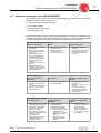
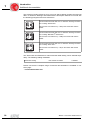
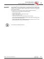
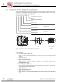
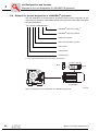
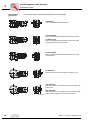
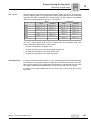
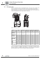
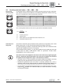
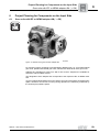
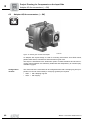
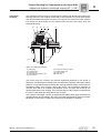
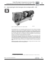
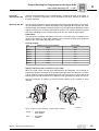
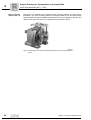
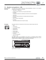
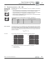
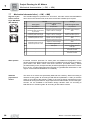
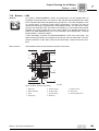
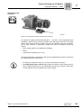
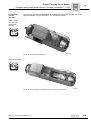
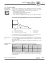
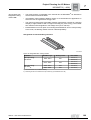
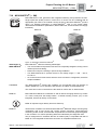
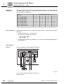
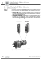
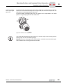
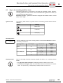
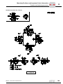
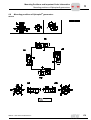
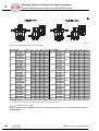
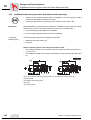
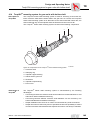
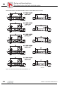
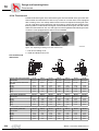
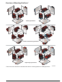
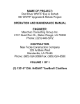
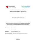
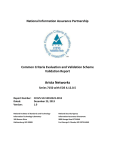
Project Planning for AC Motors
MOVIMOT® (→ MM)
7
7.17
MOVIMOT® (→ MM)
General notes
Note the following points during project planning for MOVIMOT® AC motors:
•
For detailed project planning notes, technical data and information on the communication of MOVIMOT® via fieldbus interfaces or RS-485, refer to the system folder
"Decentralized Installation" (MOVIMOT®, MOVI-SWITCH®, Communication and
Supply Interfaces).
•
The use of MOVIMOT® for lift applications is limited. Please contact SEWEURODRIVE to inquire about suitable solutions with MOVITRAC® or MOVIDRIVE®.
•
The suitable MOVIMOT® gearmotor is selected with regard to the speed, power,
torque and spatial conditions of the application (see the selection tables in the
"MOVIMOT® Gearmotors catalog). The options are then determined depending on
the control type.
MM
Functional
description
MOVIMOT® is the combination of an AC (brake) motor and a digital frequency inverter
in the power range 0.5 ... 5 Hp. It is the perfect match for decentralized drive
configurations.
MM03 - MM15
MM20 - MM30
04005AXX
Figure 65: MOVIMOT® AC motor
Features of
MOVIMOT®
MOVIMOT® is the ideal solution for a variety of decentralized drive tasks. The following
functional description provides an overview of the most important features:
•
MOVIMOT® is a gearmotor with integrated digital frequency inverter in the power
range from 0.5 ... 5 Hp and integrated brake management.
•
MOVIMOT® is available for the supply voltages 3 × 200...240 V, 50/60 Hz and
3 × 380...500 V, 50/60Hz.
•
MOVIMOT® is available for rated speeds of 1800 rpm and 3000 rpm.
•
The brake coil is used as braking resistor in motors with mechanical brake; an internal braking resistor will be a standard component of MOVIMOT® units for motors
without brake.
•
MOVIMOT® is available in two designs:
– MM..C-503-00: Standard version
– MM..C-503-30: with integrated AS-interface
128
Manual – Gear Units and Gearmotors
Project Planning for AC Motors
MOVIMOT® (→ MM)
•
Control takes place via binary signals, via the serial interface RS-485 or optionally
via all commercial fieldbus interfaces (PROFIBUS, INTERBUS, DeviceNet,
CANopen or AS-interface).
•
Overview of MOVIMOT® functions (all versions):
–
–
–
–
–
–
•
Advantages of
MOVIMOT®
Clockwise, counterclockwise operation
Changeover between two fixed setpoints
Setpoint f1 can be scaled
Ready signal to controller
Diagnostics of MOVIMOT® via status LED
Additional functions for specific applications
Additional functions of version with integrated AS-interface
–
–
–
–
•
7
Addressing via M12 (AS-interface address 1-31)
Connection option for two external sensors
Additional LED for AS-interface status
Additional diagnostic interface via modular jack 4/4 plug connector
MOVIMOT® is supplied with UL approval (UL listed) on request.
MOVIMOT® offers the following advantages:
•
Compact design
•
Interference-free connection between inverter and motor
•
Closed design with integrated protection functions
•
Inverter cooling independent of the motor speed
•
No space required in the control cabinet
•
Optimum presetting of all parameters for the expected application
•
Compliance with EMC standards EN 50 081 (interference suppression level A) and
EN 50 082
•
Easy installation, startup and maintenance
•
Easy to service for retrofitting and replacement
MOVIMOT® can be used to equip extensive systems or can be integrated into existing
systems. MOVIMOT® is also the electronic replacement for multi-speed motors or mechanical variable speed drives.
MOVIMOT® is available as motor, brake motor, gearmotors or geared brake motor in
many different standard versions and mounting positions.
Manual – Gear Units and Gearmotors
129
Project Planning for AC Motors
MOVIMOT® (→ MM)
7
Connection technology MOVIMOT® standard design
Overview
MOVIMOT® MM..C-503-00 is supplied without plug connector if not specified otherwise
in the order. The plug connectors listed in the following table are preferred components.
For other types, please contact SEW-EURODRIVE.
Order designation
Function
Terminal box
design
Manufacturer designation
MM../AVT1
RS-485
Standard
M12 x 1 round plug connector
MM../RE.A/ASA3
RE1A = MM03-15
RE2A = MM22-3X
Power
Modular
Harting HAN® 10 ES pin element
(built-on housing with two clips)
MM../RE.A/ASA3/AVT1
RE1A = MM03-15
RE2A = MM22-3X
Power/RS-485
Modular
Harting HAN® 10 ES pin element
(built-on housing with two clips) +
M12 x 1 round plug connector
MM../RE.A/AMA6
RE1A = MM03-15
RE2A = MM22-3X
Power/RS-485
Modular
Harting HAN® modular pin element
(built-on housing with two clips)
Terminal box design:
The modular terminal box offers the following functions compared to the standard
terminal box:
Possible plug
connector
positions
•
The position of the cable entries/plug connectors can later be turned to the opposite
side (see "MOVIMOT®" operating instructions).
•
Integration of brake control systems (see Sec. "Options")
The following positions are possible for plug connectors:
Plug connector
Possible positions
AVT1
X (standard)
2
RE.A/ASA3
X (standard)
2
RE.A/ASA3/AVT1
ASA3 = X (standard) + AVT1 = X (standard)
ASA3 = 2 + AVT1 = 2
ASA3 = X + AVT1 = 2
ASA3 = 2 + AVT1 = X
RE.A/AMA6
X (standard)
2
X
270˚ (T)
2
2
2
2
(R) 0˚
180˚ (L)
X
X
X
2
90˚(B)
X
52532AXX
Figure 66: Possible plug connector positions
130
Manual – Gear Units and Gearmotors
Project Planning for AC Motors
MOVIMOT® (→ MM)
7
MOVIMOT® operating modes
4Q operation of
motors with
mechanical brake
•
The brake coil is used as braking resistor in 4Q operation.
•
No external braking resistor may be connected.
•
Brake voltage is generated internally within the unit, which means it is mainsindependent.
Resistance and assignment of the brake coil:
Motor
Resistance of the brake coil1)
Brake
MOVIMOT® with 380–500 VAC
input voltage
MOVIMOT® with 200–240 VAC
input voltage
DT71
BMG05
277 Ω(230 V)
69,6 Ω(110 V)
DT80
BMG1
248 Ω(230 V)
62,2 Ω(110 V)
DT90
BMG2
216 Ω (230 V) / 54.2 Ω (110 V)
54,2 Ω(110 V)
DV100/DT100
BMG4
43.5 Ω(110 V)
27.3 Ω (88 V)
1) Rated value measured between the red connection (terminal 13) and the blue connection (terminal 15) at
20°C, temperature-dependent fluctuations in the range -25% / +40 % are possible.
Regenerative load capacity of the brake coil (MOVIMOT® with 380 – 500 VAC
supply voltage)
20.000
[1]
[J]
15.000
[2]
10.000
[3]
5.000
[4]
0
10
100
1.000
10.000
[c/h]
52711AXX
Figure 67: Regenerative load capacity
[c/h]
[1]
[2]
[3]
[4]
Cycles per hour
BMG2/BMG4 (110 V)
BMG2
(230 V)
BMG1
(230 V)
BMG05
(230 V)
Manual – Gear Units and Gearmotors
131
7
Project Planning for AC Motors
MOVIMOT® (→ MM)
Regenerative load capacity of the brake coil (MOVIMOT® with 200...240 VAC
supply voltage)
20.000
[1]
[J]
15.000
10.000
[2]
[3]
5.000
0
1
10
100
[c/h]
1.000
10.000
52712AXX
Figure 68: Regenerative load capacity
[c/h]
[1]
[2]
[3]
132
Cycles per hour
BMG2 (110 V), BMG4 (88 V)
BMG1 (110 V)
BMG05 (110 V)
Manual – Gear Units and Gearmotors
Project Planning for AC Motors
MOVIMOT® (→ MM)
4Q operation with
integrated braking
resistor BW..
7
•
The brake resistor is integrated in the terminal box of MOVIMOT® as standard in
motors without mechanical brake.
•
4Q operation with integrated braking resistor is recommended for applications in
which the level of regenerative energy is low.
•
The resistor protects itself (reversible) against regenerative overload by changing
abruptly to high resistance and no longer consuming any more energy. The inverter
then switches off and signals an overvoltage error (error code 04).
•
Field distributors or P2.A option for mounting the MOVIMOT® unit in close proximity
to the motor, the braking resistor must be ordered separately.
Assignment of internal braking resistors:
52714AXX
Figure 69: Integrated BW.. braking resistor
MOVIMOT®
with input voltage
380–500 VAC
with input voltage
200–240 VAC
MOVIMOT® type
Braking resistor
MM03..MM15
BW1
MM22..MM3X
BW2
MM03..MM07
BW3
823 598 82)
MM11..MM22
BW4
823 599 62)
Part number
822 897 31)
800 621 02)
823 136 21)
800 622 92)
1) Two screws M4 x 8, included in delivery
2) Retaining screws not included in scope of delivery (not available in the US)
Manual – Gear Units and Gearmotors
133
7
Project Planning for AC Motors
MOVIMOT® (→ MM)
Regenerative load capacity of internal braking resistors:
BW2 BW1
BW4 BW3
1200
600
[1]
[J]
1000
500
800
400
600
300
400
200
200
100
0
[2]
[3]
0
0
10
50
100
200
500
1000
[c/h]
2000
3000
4000
5000
6000
52713AXX
Figure 70: Regenerative load capacity
[c/h]
[1]
[2]
[3]
134
Cycles per hour
Brake ramp 10 s
Brake ramp 4 s
Brake ramp 0.2 s
Manual – Gear Units and Gearmotors
Project Planning for AC Motors
MOVIMOT® (→ MM)
4Q operation with
brake and external
braking resistor
7
•
4Q operation with external braking resistor is recommended for applications in which
the level of regenerative energy is high.
•
External braking resistors are only permitted with brake motors in combination with
brake control BGM/BSM.
•
When using external braking resistors and BGM/BSM brake control, MOVIMOT®
special functions must be activated. Refer to the MOVIMOT® operating instructions
for more information.
Assignment of external braking resistors:
MOVIMOT®
MOVIMOT® type
Braking resistor
Part number
BW200-300
826 267 5
BW200-005
826 270 5
BW200-003/K-1.5
828 291 9
with input voltage
380–500 VAC
MM03..MM15
MM22..MM3X
BW200-005/K-1.5
828 283 8
BW150-010
802 285 2
BW100-003
826 266 7
BW100-005
826 269 1
BW100-003/K-1.5
828 293 5
BW100-005/K-1.5
828 286 2
BW068-010
802 287 9
BW068-020
802 286 0
Power diagrams of external braking resistors:
3
4
5
6
7
8 9 10
30
40
50
60
70 80
100
2.0
100/200 - 005
1.0
0.8
[1]
20
1.0
0.8
0.6
0.6
0.4
0.4
100/200 - 003
0.2
0.1
3
4
5
6
7
8 9 10
[3]
2.0
0.2
20
[2]
30
40
50
60
70 80
0.1
100
59788AXX
Figure 71: Power diagrams of braking resistors BW100-003, BW200-003, BW100-005 and
BW200-005
[1]
[2]
[3]
Short-term power in kW
Cyclic duration factor cdf in %
Continuous power 100 % cdf in kW
Manual – Gear Units and Gearmotors
135
Project Planning for AC Motors
MOVIMOT® (→ MM)
10
8
3
4
5
6
7
8 9 10
20
30
40
6
50
60
70 80
100
10
8
6
068 - 020
4
[1]
4
2
2
068 - 010
1
0.8
1
0.8
0.6
0.6
0.4
3
4
5
6
7
8 9 10
20
[2]
30
40
50
60
70 80
[3]
7
0.4
100
59789AXX
Figure 72: Power diagrams of braking resistors BW068-010 and BW068-020
Short-term power in KW
Cyclic duration factor cdf in %
Continuous power 100 % cdf in KW
10
8
3
4
5
6
7
8 9 10
20
30
40
50
60
70 80
100
10
8
6
6
[1]
4
4
068 - 020
2
2
068 - 010
1
0.8
1
0.8
0.6
0.6
0.4
[3]
[1]
[2]
[3]
3
4
5
6
7
8 9 10
20
[2]
30
40
50
60
70 80
0.4
100
59795AXX
Figure 73: Power diagrams of braking resistors BW068-010 and BW068-020 according to
UL approval
[1]
[2]
[3]
136
Short-term power in KW
Cyclic duration factor cdf in %
Continuous power 100 % cdf in KW
Manual – Gear Units and Gearmotors
Project Planning for AC Motors
MOVI-SWITCH® (→ GM)
7.18
7
MOVI-SWITCH® (→ GM)
GM
MOVI-SWITCH® is the gearmotor with integrated switching and protection function.
Single speed AC (brake) motors in sizes DT71 to DV100 can be combined with all
appropriate gear units in the modular concept as part of the MOVI-SWITCH® product
range. For detailed information on MOVI-SWITCH®, refer to the system folder
"Decentralized Installation" (MOVIMOT®, MOVI-SWITCH®, Communication and Supply
Interfaces).
MSW-1E
Figure 74: Gearmotor with MOVI-SWITCH®
Advantages of
MOVI-SWITCH®
2 versions
MSW-2S
MSW1E_MSW2S
MOVI-SWITCH® offers the following advantages:
•
The circuit breaker and protection functions are completely integrated, saving control
cabinet space and cabling.
•
Robust and compact, resulting in space-saving installation.
•
Use MOVI-SWITCH® to operate motors in the voltage range 3 × 380 ... 500 V,
50 / 60 Hz.
•
AC motors and AC brake motors with the same connection configuration, therefore
simple installation.
Two MOVI-SWITCH® versions are available: one for operation with one direction of
rotation (MSW-1E); one for operation with direction of rotation reversal (MSW-2S).
The mains and control connections are the same for motors with or without brake.
MSW-1E
MOVI-SWITCH® MSW-1E is switched on and off without changing direction by means
of a short circuit-proof star bridge switch. A thermal winding monitor (TF) is also
integrated, which acts directly on the switch.
MSW-1E requires longer delivery time from Germany.
MSW-2S
The direction of rotation is reversed in MOVI-SWITCH® MSW-2S using a reversing relay
combination with a long service life. Supply system monitoring, phase-sequence
monitoring, brake control, circuit breaker and protection functions are grouped together
in the controller. The various operating states are indicated by the diagnostic LED.
The pin assignment for clockwise direction of rotation (CW) is compatible with that of
MSW-1E. The integrated AS-interface connection is compatible with MLK11A.
Manual – Gear Units and Gearmotors
137
Project Planning for AC Motors
MOVI-SWITCH® (→ GM)
7
Available
combinations
The following MOVI-SWITCH® AC motors and AC brake motors can be combined with
all suitable gear unit types, mounting positions and versions in accordance with the
selection tables for gearmotors.
Power [HP] with pole number
Motor size
Order information
2
4
6
8
DT71D.. (/BMG)/TF/MSW..
0.75
0.50
0.33
0.20
DT80K.. (/BMG)/TF/MSW..
1.0
0.75
0.50
-
DT80N.. (/BMG)/TF/MSW..
1.5
1.0
0.75
0.33
DT90S.. (/BMG)/TF/MSW..
2.0
1.5
1.0
0.50
DT90L.. (/BMG)/TF/MSW..
3.0
2.0
1.5
0.75
DV100M.. (/BMG)/TF/MSW..
4.0
3.0
2.0
1.0
DV100L.. (/BMG)/TF/MSW..
-
4.0
-
1.5
Note the following points when ordering AC (brake) motors or gearmotors with MOVISWITCH®:
•
Voltage for winding in 댴 connection only.
•
Only two brake voltages are possible:
– Motor voltage / √3 or
– motor voltage.
•
Position of the terminal box preferably 270°. Please consult SEW-EURODRIVE for
other positions.
Block diagram
MSW-1E
Theory of operation of MOVI-SWITCH® MSW-1E:
MOVI-SWITCH ® -1E
[1]
0V
OK
24V
Run
&
U2 V2 W2
U1 V1 W1
4
3
1
2
3
4
2
1
0V RUN 24V OK
L1
L2
L3
Figure 75: Block diagram MOVI-SWITCH® MSW-1E
51946AXX
[1] Brake control
138
Manual – Gear Units and Gearmotors
Project Planning for AC Motors
MOVI-SWITCH® (→ GM)
MSW-2S with
binary control
7
Theory of operation of MOVI-SWITCH® MSW-2S with binary control:
MOVI-SWITCH® -2S
[1]
U2 V2 W2
U1 V1 W1
[2]
4
4
11
33
22
33 44
22
11
4
4
11
33
2
2
33 44
22
11
0V 24V 0V 24V
CW OK CW CCW
L1 L2 L3
Figure 76: Block diagram MOVI-SWITCH® MSW-2S with binary control
[1]
Brake control
[2]
Rotating field detection
Manual – Gear Units and Gearmotors
51945AXX
139
7
Project Planning for AC Motors
MOVI-SWITCH® (→ GM)
MSW-2S with ASinterface control
Theory of operation of MOVI-SWITCH® MSW-2S with AS-interface control:
AS - AS + DI2 DI3
0V 24V 24V
0V
L1 L2 L3
Figure 77: Block diagram of MOVI-SWITCH® MSW-2S with AS-interface control
140
[1]
Brake control
[2]
Rotating field detection
AS
AS-interface
06454AXX
Manual – Gear Units and Gearmotors
Project Planning for AC Motors
WPU smooth multi-speed unit (→ GM)
7.19
7
WPU smooth multi-speed unit (→ GM)
GM
Function
Normal mulit-speed motors cannot switch from high to low speed without jerks unless
special measures are taken. In order to limit the occurring regenerative braking torque,
either the voltage is reduced to a lower value at the moment of changeover through
chokes, a transformer or dropping resistors, or only 2-phase switchover takes place. All
mentioned measures involve additional installation effort and switchgear. A time relay
causes the voltage to return to normal voltage conditions. The relay is adjustable. The
WPU unit operates purely electronically.
The changeover command blocks a phase of the mains voltage using a triac and in this
way reduces the shifting down torque to about a third. As soon as the synchronous
speed of the high-pole winding is reached, the third phase is activated again in a current
optimized manner.
03100AXX
Figure 78: Smooth pole-change unit WPU
Advantages of
WPU
•
Load independent and wear-free
•
No energy loss which means high efficiency
•
No restriction on start-up and rated torque and no restriction on the motor starting
frequency
•
Minimum wiring
•
Suitable for any standard motor
Technical data
Type
WPU 1001
WPU 1003
WPU 1010
WPU 2030
Part number
825 742 6
825 743 4
825 744 2
825 745 0
0.2 ... 1 AAC
1 ... 3 AAC
3 ... 10 AAC
10 ... 30 AAC
For mulit-speed motors with rated
current at low speed
IN
0.2 ... 1 AAC
in S3 intermittent periodic duty 40/60% cdf
1 ... 5 AAC
3 ... 15 AAC
10 ... 50 AAC
For multi-speed motors with rated
current at low speed
in S1 continuous running duty
IN
Rated supply voltage
Usupply
2 × 150...500 VAC
Supply frequency
fsupply
50/60 Hz
Rated current in S1 continuous running
duty
IN
Ambient temperature
1 AAC
ϑUmg
3 AAC
Mechanical design
Manual – Gear Units and Gearmotors
30 AAC
-15 ... +45°C
Enclosure
Weight
10 AAC
IP20
0.66 lb
0.66 lb
DIN rail housing with
screw connections
1.32 lb
3.31 lb
Control cabinet
rear panel
141
Project Planning for AC Motors with Inverter
Operation on inverter
8
8
Project Planning for AC Motors with Inverter
8.1
Operation on inverter
Range of
products
The extensive product range of SEW-EURODRIVE inverters is available for designing
electronically controlled drives. SEW-EURODRIVE offers the following inverter series:
•
MOVITRAC® B: Compact and inexpensive frequency inverter for the power range
0.3-175HP. Single-phase and three-phase supply connection for 230 VAC and threephase supply connection for 460 VAC.
•
MOVIDRIVE® MDX60/61B: High-performance drive inverter for dynamic drives in
the power range 0.75-175HP. Great diversity of applications due to extensiveexpansion options with technology and communication options. Three phase supply
connection for 230 VAC and 460 VAC
MOVITRAC®B
MOVIDRIVE®
MDX60/61B
59188AXX
Figure 79: Range of inverters for AC motors
142
Manual – Gear Units and Gearmotors
Project Planning for AC Motors with Inverter
Operation on inverter
Product
characteristics
8
The following table lists the most important product characteristics for the various
inverter series. The overview of product characteristics can help you to choose the
suitable inverter series for your application.
Product characteristics
Voltage range
Power range
MOVITRAC® B
MOVIDRIVE® MDX60/61B
1 × 200 ... 240 VAC (limited power
range)
3 × 200 ... 240 VAC (limited power
range)
3 × 380 ... 500 VAC
3 × 200 ... 240 VAC (limited power
range)
3 × 380 ... 500 VAC
0.3-175HP
0.75-175HP
150% IN1) briefly and 125% IN permanently during operation without
overload
Overload capacity
4Q capable
Yes, with integrated brake chopper as standard.
At 1 × 200 ... 240 VAC: according
to class B limit
At 3 × 200 ... 240 VAC und 3 ×380
... 500 VAC: sizes 0, 1 and 2
according to class A limit
Integrated line filter
TF input
Sizes 0, 1 and 2
according to class A limit
Yes
U/f or voltage-controlled flux vector control (VFC)
U/f or voltage-controlled flux vector control (VFC), with speed
feedback speed control and current-controlled flux vector control
(CFC).
Speed feedback
No
Option
Integrated positioning and
sequence control system
No
Standard
Control mode
System bus (SBus)
and RS-485
Serial interfaces
Fieldbus interfaces
Optional via gateway PROFIBUS,
INTERBUS, CANopen, DeviceNet, Ethernet
Optional PROFIBUS-DP, INTERBUS, INTERBUS LWL,
CANopen, DeviceNet, Ethernet
Technology options
IEC 61131 control
Input/output card
Synchronous operation
Absolute encoder card
IEC 61131 control
Yes
Yes
Safe stop
Approvals
UL and cUL approval, C-tick
®
1) Only for MOVIDRIVE MDX60/61B: The short-time overload capacity is 200% IN for units of size 0 (0005
...0014).
Manual – Gear Units and Gearmotors
143
Project Planning for AC Motors with Inverter
Drive properties
8
8.2
Drive properties
The required drive properties are the main factors determining the selection of the
inverter. The following illustration serves as assistance for inverter selection.
System selection
Positioning accuracy of the motor
shaft
< ±360°
< ±5°...45°
< ±1°
U/f without encoder or voltage-controlled flux vector control (VFC)
without encoder.
–
–
Setting range (reference 3000 rpm)
MOVITRAC® B
MOVIDRIVE® MDX60/61B
1:200
1:800
> 1:800
U/f with encoder or voltage-controlled
flux vector control (VFC) with
encoder.
–
MOVIDRIVE® MDX61B with
DEH11B option
Motor selection for U/f and VFC
– Max. torque < 150 % TN
– Max. speed < 140 % nEck
– Thermal load (setting range, cyclic duration factor)
– Selection of the correct encoder (if necessary)
Control
Pos. reg.
n reg.
M reg.
Current-controlled flux vector control
(CFC) with encoder
–
MOVIDRIVE® MDX61B with
DEH11B option
Motor selection for CFC
– Max. torque < 300 % TN for asynchronous servomotors and < 180 % YN for AC gearmotors
– R.m.s. torque < TN at average speed
– Torque characteristic curves
– Selecting the correct encoder (for example Hiperface ®
encoder only with MCH units)
Key
144
Pos. reg.
= Positioning control
n reg.
= Speed control
T reg.
= Torque control
VFC
= Voltage flux control
CFC
= Current flux control
TN
= Rated torque of the motor
ntrans
= Rated speed (transition speed) of the motor
Manual – Gear Units and Gearmotors
Project Planning for AC Motors with Inverter
Selecting the inverter
8.3
8
Selecting the inverter
Drive categories
The large number of different drive applications can be divided into five categories. The
five categories are listed below together with the recommended inverter. The assignment is based on the required setting range and the resulting control process.
1. Drives with a base load and a speed dependent load, such as conveyor drives.
•
Low requirements on the setting range.
– MOVITRAC® B
– MOVIDRIVE® MDX60/61B
•
High requirements on the setting range (motor with encoder).
– MOVIDRIVE® MDX61B with DEH11B option
2. Dynamic load, e.g. trolleys; brief high torque demand for acceleration followed by low
load.
•
Low requirements on the setting range.
– MOVITRAC® B
– MOVIDRIVE® MDX60/61B
•
High requirements on the setting range (motor with encoder).
– MOVIDRIVE® MDX61B with DEH11B option
•
High dynamic properties required (motor with encoder, preferably sin/cos encoder).
– MOVIDRIVE® MDX61B with DEH11B option
3. Static load, e.g. hoists; mainly steady high static load with overload peaks.
•
Low requirements on the setting range.
– MOVITRAC® B
– MOVIDRIVE® MDX60/61B
•
High requirements on the setting range (motor with encoder).
– MOVIDRIVE® MDX61B with DEH11B option
4. Load falling in inverse proportion to speed, e.g. winding or coil drives.
•
Torque control (motor with encoder, preferably sin/cos encoder).
– MOVIDRIVE® MDX61B with DEH11B option
5. Variable torque load, e.g. fans and pumps.
•
Low load at low speeds and no load peaks, 125% utilization (ID = 125% IN).
– MOVITRAC® B
– MOVIDRIVE® MDX60/61B
Manual – Gear Units and Gearmotors
145
Project Planning for AC Motors with Inverter
Selecting the inverter
8
Further selection
criteria
Power range
•
Communication options (serial interfaces, fieldbus)
•
Expansion options (such as synchronous operation)
•
PLC functionality (IPOSplus®, application modules)
Additional
documentation
For detailed information and additional project planning instructions on the individual
inverter series, refer to the manuals and catalogs of electronically controlled drives. The
SEW-EURODRIVE homepage (http://www.seweurodrive.com) provides links to a wide
selection of our documentation in various languages for download as PDF files.
Electronics
documentation
Other documents that are of interest in terms of project planning are given below. You
can order these publications from SEW-EURODRIVE.
Motor selection
146
•
•
MOVITRAC® B system manual
•
MOVIDRIVE® MDX60/61B system manual
Note the thermally approved torque when selecting the motor. Section 14.3 lists the
torque limiting curves of 4-pole asynchronous AC motor DR, DT, DV. Use these limiting
curves to determine the thermally approved torque.
Manual – Gear Units and Gearmotors
Project Planning for AC Motors with Inverter
Torque limit curves with inverter operation
8.4
8
Torque limit curves with inverter operation
Thermally
approved torque
Note thermally approved torque in project planning for operation of DR, DT, DV
asynchronous AC motors with frequency inverter. The following factors determine the
thermally permitted torque:
•
Duty type
•
Type of cooling: Self-ventilation or forced cooling
•
Base frequency fbase = 60 Hz (460 V 댴) or fbase = 120Hz (230 댴댴
Use the torque limit curves to determine the thermally permitted torque. The projected,
effective torque has to be less than the limit curve value. The following illustration shows
the limit curves for 4-pole DR, DT, DV asynchronous AC motors with fbase = 60 Hz and
fbase = 120 Hz. The following peripheral conditions apply to the shown limit curves:
fbase = 60 Hz
(460 V 댴/60 Hz)
•
Duty type S1
•
Supply voltage of the inverter Usupply = 3 × 460 VAC
•
Motor in thermal class F
The following diagram shows the limit curves for operation at fbase = 60 Hz. The curves
are different for those motors with self-ventilation and those with forced cooling (=
optional forced cooling fan).
2
3.
1.8
1.6
460 V /60Hz
1.4
T /TR
1.2
2.
1
0.8
1.
0.6
0.4
0.2
0
0
500
1000
1500
2000
2500
3000
3500
rpm
60850AXX
Figure 80: Torque limit curves for fbase = 60 Hz
1. S1 operation with self-ventilation (= without forced cooling fan)
2. S1 operation with forced cooling (= with forced cooling fan)
3. Mechanical limitations for gearmotors
Manual – Gear Units and Gearmotors
147
8
Project Planning for AC Motors with Inverter
Torque limit curves with inverter operation
fbase = 120 Hz
(230 V 댴댴/60 Hz)
The following diagram shows the limit curves for operation at fbase = 120 Hz. The curves
are different for those motors with self-ventilation and those with forced cooling (=
optional forced cooling fan).
2
4.
1.8
1.6
230 V
T /TR
1.4
/60Hz
1.2
2.
1
1.
3.
0.8
1.
0.6
0.4
0.2
0
0
500
1000
1500
2000
2500
3000
3500
rpm
60851AXX
Figure 81: Torque limit curves for fbase = 120 Hz
1. S1 operation with self-ventilation (= without forced cooling fan)
2. S1 operation with forced cooling (= with forced cooling fan)
3. S1 operation with self-ventilation (+without forced cooling fan)>160M
4. Mechanical limitations for gearmotors
148
Manual – Gear Units and Gearmotors
Mounting Positions and Important Order Information
General information on mounting positions M1 … M6
9
Mounting Positions and Important Order Information
9.1
General information on mounting positions
9
Mounting position designation
SEW-EURODRIVE differentiates between six mounting positions M1 ... M6 for gear units, gearmotors and
MOVIMOT® gearmotors . The following figure shows the position of the gear unit in mounting positions M1 ...
M6.
M6
M6
M1
M1
M2
M2
M5
M5
M4
M4
R..
M3
M3
M6
M6
M1
M2
M2
M1
M5
M5
M4
M4
F..
M3
M3
M6
M1
M1
M6
M2
M5
M5
M2
M4
M4
M3
K..
S..
W..
M3
03203AXX
Figure 82: Depiction of mounting positions M1 ... M6
Manual – Gear Units and Gearmotors
149
9
M1 … M6
9.2
Mounting Positions and Important Order Information
Important order information
The following order information is required for R, F, K and S gear units and gearmotors
in addition to the mounting position to exactly determine the design of the drive.
This information is also required for Spiroplan® gearmotors (W gearmotors) that do not
depend on a particular mounting position.
The following
applies to all gear
units and gearmotors
Observe the following notes for all gear units, gearmotors and MOVIMOT® gearmotors
from SEW-EURODRIVE.
Direction of
rotation of the
output with a backstop
If the drive has a backstop RS, you have to indicate the direction of rotation of the output
for the drive. The following definition applies:
As viewed at the output shaft:
Clockwise (CW) = Rotating clockwise
Counterclockwise (CCW)= Rotating counterclockwise
B
A
CCW
CW
CCW
CW
57504AXX
Figure 83: Direction of rotation of output
In right-angle gear units, you also have to indicate whether the direction of rotation is
given looking onto the A or B end.
Position of the
output shaft and
output flange
In right-angle gear units, you also have to indicate the position of the output shaft and
the output flange:
•
A or B or AB (→ Figure 84)
B
A
57505AXX
Figure 84: Position of the output shaft and the output flange
150
Manual – Gear Units and Gearmotors
Mounting Positions and Important Order Information
Important order information M1 … M6
Position of output
end in right-angle
gear units
9
In shaft mounted right-angle gear units with a shrink disc, you also have to indicate
whether the A or B end is the output end. In Figure 85, the A end is the output end. The
shrink disc is located opposite the output end.
In shaft mounted right-angle gear units, the "output end" is equivalent to the "shaft
position" of right-angle gear units with solid shaft.
A
B
57506AXX
Figure 85: Position of the output end
You will find the permitted mounting surfaces (= hatched area) in the mounting position
sheets (page 156 and the following pages).
Example: Only the mounting surface at the bottom is possible with helical-bevel gear
units K167/K187 in mounting positions M5 and M6.
Manual – Gear Units and Gearmotors
151
9
M1 … M6
Mounting Positions and Important Order Information
Important order information
For all
gearmotors
Observe the following notes for all gearmotors and MOVIMOT® gearmotors from SEWEURODRIVE.
Position terminal
box and cable
entry
The position of the motor terminal box has so far been specified indicated with 0°, 90°,
180° or 270° as viewed onto the fan guard = B-end (→ Figure 86). A change in the
product standard EN 60034 specifies that the following designations will have to be
used for terminal box positions for foot-mounted motors in the future:
•
As viewed onto the output shaft = A-end
•
Designation as R (right), B (bottom), L (left) and T (top)
This new designation applies to foot-mounted motors without a gear unit in mounting
position B3 (= M1). The previous designation is retained for gearmotors. Figure 86
shows both designations. Where the mounting position of the motor changes, R, B, L
and T are rotated accordingly. In motor mounting position B8 (= M3), T is at the bottom.
The position of the cable entry can be selected as well. The positions are "X" (= standard
position), "1", "2" or "3" (→ Figure 86).
X
270° (T)
2
2
1
3
X
180° (L)
180° (L)
0°(R)
1
X
X
3
X
0° (R)
90° (B)
51302AUS07
Figure 86: Position of terminal box and cable entry
Unless indicated otherwise, you will receive the terminal box type 0° (R) with cable entry
"X". We recommend selecting cable entry "2" with mounting position M3.
152
•
When the terminal box is in the 90° (B) position, check to see if the gearmotor has
to be supported.
•
Only cable entries "X" and "2" are possible for DT56 and DR63 motors. Exception:
Cable entry "3" is also possible for DR63 with IS plug connector.
•
The following cable entries are possible in the DT71..BMG motor with gear unit
flange diameters 160 mm and 200 mm:
Terminal box position
0° (R)
90° (B)
180° (L)
270° (T)
Possible cable entries
"X", "3"
"X", "1", "3"
"1", "2"
"X", "1", "3"
Manual – Gear Units and Gearmotors
Mounting Positions and Important Order Information
Important order information M1 … M6
Applies to all
MOVIMOT®
gearmotors
The following information applies to MOVIMOT® gearmotors in addition to the gearmotors.
Position terminal
box and cable
entry
Position of the terminal box (MOVIMOT® inverter):
9
Not all positions are possible with MOVIMOT® gearmotors. Note the information in
section "Position of the terminal box (MOVIMOT® inverter)" on page 180.
Position of the cable entry:
You do not have to select the position of the cable entry for MOVIMOT® gearmotors.
Positions "X" (= standard position) and position "2" are always possible (see Figure 87).
Position of plug connectors options:
You will have to select the position for MOVIMOT® optional plug connectors (e.g. ASA3)
(see Figure 87).
Not all position are possible. See the notes in the section "Mounting Positions, Technical
Data and Dimension Sheets MOVIMOT®".
X
270˚ (T)
2
2
2
2
(R) 0˚
180˚ (L)
X
X
X
2
90˚(B)
X
50947AXX
Figure 87: Position terminal box and cable entry, plug connectors
Manual – Gear Units and Gearmotors
153
9
M1 … M6
Mounting Positions and Important Order Information
Important order information
Sample orders
Mounting
position
Shaft
position
Flange
position
Terminal
box
position
Position of
cable entry
Direction of
rotation of
output
K47../RS
M2
A
-
0°
"X"
CW
SF77DV100L4
M6
AB
AB
90°
"3"
-
KA97DV132M4
M4
B
-
270°
"2"
-
KH107DV160L4
M1
A
-
180°
"3"
-
-
A
A
0°
"X"
-
M3
A
B
-
-
-
Type
(Examples)
WF20DT71D4
KAF67A
Change in
mounting
position
154
Make sure to read the following information when you operate the gearmotor in a
mounting position other than the one indicated in the order:
•
Adjust lubricant fill quantity to match the new mounting position
•
Adjust position of breather valve
•
For helical-bevel gearmotors: Contact the SEW-EURODRIVE customer service prior
to changing to mounting position M5 or M6 and when changing from M5 to M6 or vice
versa.
•
For helical-worm gearmotors: Contact the SEW-EURODRIVE customer service
when changing to mounting position M2.
Manual – Gear Units and Gearmotors
Mounting Positions and Important Order Information
Key to the mounting position sheets M1 … M6
9.3
9
Key to the mounting position sheets
Spiroplan® gearmotors do not depend on any particular mounting position. However,
mounting positions M1 to M6 are also shown for SPIROPLAN® gearmotors to assist you
in working with this documentation.
Important: Spiroplan® gearmotors cannot be equipped with breather valves, oil level
plugs or drain plugs.
Symbols used
The following table shows the symbols used in the mounting position sheets and their
meaning:
Symbol
Meaning
Breather valve
Oil level plug
Oil drain plug
Churning losses
Churning losses may occur in some mounting positions. Contact SEW-EURODRIVE in case of
the following combinations:
* → page 45
Mounting position
M2, M4
Gear unit type
R
F
M2, M3, M4, M5, M6
K
S
Displayed shaft
Gear unit size
Input speed
[1/min]
97 ... 107
> 2500
> 107
>1500
97 ... 107
> 2500
> 107
> 1500
77 ... 107
> 2500
> 107
> 1500
77 ... 97
> 2500
Note the following information regarding display of shafts in the mounting position
sheets:
•
For gear units with solid shaft: The displayed shaft is always on the A end.
•
For shaft mounted gear units: The shaft with dashed lines represents the customer
shaft. The output end (Ⳏ shaft position) is always shown on the A end.
Manual – Gear Units and Gearmotors
155
9
M1 … M6
9.4
Mounting Positions and Important Order Information
Mounting positions of helical gearmotors
RX57-RX107
* → page 155
156
Manual – Gear Units and Gearmotors
Mounting Positions and Important Order Information
Mounting positions of helical gearmotors M1 … M6
9
RXF57-RXF107
* → page 155
Manual – Gear Units and Gearmotors
157
9
M1 … M6
Mounting Positions and Important Order Information
Mounting positions of helical gearmotors
R07-R167
* → page 155
158
Manual – Gear Units and Gearmotors
Mounting Positions and Important Order Information
Mounting positions of helical gearmotors M1 … M6
9
RF07-RF167, RZ07-RZ87
* → page 155
Manual – Gear Units and Gearmotors
159
9
M1 … M6
Mounting Positions and Important Order Information
Mounting positions of helical gearmotors
R07F-R87F
* → page 155
Important: See the
160
information in the section "Project Planning for Gear Units/Overhung and axial loads" (page 51).
Manual – Gear Units and Gearmotors
Mounting Positions and Important Order Information
Parallel shaft helical gearmotors M1 … M6
9.5
9
Parallel shaft helical gearmotors
F/FA..B/FH27B-157B, FV27B-107B
* → page 155
Manual – Gear Units and Gearmotors
161
9
M1 … M6
Mounting Positions and Important Order Information
Parallel shaft helical gearmotors
FF/FAF/FHF/FAZ/FHZ27-157, FVF/FVZ27-107
* → page 155
162
Manual – Gear Units and Gearmotors
Mounting Positions and Important Order Information
Parallel shaft helical gearmotors M1 … M6
9
FA/FH27-157, FV27-107, FT37-97
* → page 155
Manual – Gear Units and Gearmotors
163
9
M1 … M6
9.6
Mounting Positions and Important Order Information
Mounting positions of helical-bevel gearmotors
K/KA..B/KH37B-157B, KV37B-107B
* → page 155
Important: See the
164
information in the section "Project Planning for Gear Units/Overhung and axial loads" (page 51).
Manual – Gear Units and Gearmotors
Mounting Positions and Important Order Information
Mounting positions of helical-bevel gearmotors M1 … M6
9
K167-187, KH167B-187B
* → page 155
Important: See the
information in the section "Project Planning for Gear Units/Overhung and axial loads" (page 51).
Manual – Gear Units and Gearmotors
165
9
M1 … M6
Mounting Positions and Important Order Information
Mounting positions of helical-bevel gearmotors
KF/KAF/KHF/KAZ/KHZ37-157, KVF/KVZ37-107
* → page 155
166
Manual – Gear Units and Gearmotors
Mounting Positions and Important Order Information
Mounting positions of helical-bevel gearmotors M1 … M6
9
KA/KH37-157, KV37-107, KT37-97
* → page 155
Manual – Gear Units and Gearmotors
167
9
M1 … M6
Mounting Positions and Important Order Information
Mounting positions of helical-bevel gearmotors
KH167-187
* → page 155
168
Manual – Gear Units and Gearmotors
Mounting Positions and Important Order Information
Mounting positions of helical-worm gearmotors M1 … M6
9.7
9
Mounting positions of helical-worm gearmotors
S37
* → page 155
Important: See the
information in the section "Project Planning for Gear Units/Overhung and axial loads" (page 51).
Manual – Gear Units and Gearmotors
169
9
M1 … M6
Mounting Positions and Important Order Information
Mounting positions of helical-worm gearmotors
S47 - S97
* → page 155
Important: See the
170
information in the section "Project Planning for Gear Units/Overhung and axial loads" (page 51).
Manual – Gear Units and Gearmotors
Mounting Positions and Important Order Information
Mounting positions of helical-worm gearmotors M1 … M6
9
SF/SAF/SHF37
* → page 155
Manual – Gear Units and Gearmotors
171
9
M1 … M6
Mounting Positions and Important Order Information
Mounting positions of helical-worm gearmotors
SF/SAF/SHF/SAZ/SHZ47-97
* → page 155
172
Manual – Gear Units and Gearmotors
Mounting Positions and Important Order Information
Mounting positions of helical-worm gearmotors M1 … M6
9
SA/SH/ST37
* → page 155
Manual – Gear Units and Gearmotors
173
9
M1 … M6
Mounting Positions and Important Order Information
Mounting positions of helical-worm gearmotors
SA/SH/ST47-97
* → page 155
174
Manual – Gear Units and Gearmotors
Mounting Positions and Important Order Information
Mounting positions of Spiroplan® gearmotors M1 … M6
9.8
9
Mounting positions of Spiroplan® gearmotors
W10-30
→ page 155
Manual – Gear Units and Gearmotors
175
9
M1 … M6
Mounting Positions and Important Order Information
Mounting positions of Spiroplan® gearmotors
WF10-30
→ page 155
176
Manual – Gear Units and Gearmotors
Mounting Positions and Important Order Information
Mounting positions of Spiroplan® gearmotors M1 … M6
9
WA10-30
→ page 155
Manual – Gear Units and Gearmotors
177
9
M1 … M6
9.9
Mounting Positions and Important Order Information
Mounting po