1
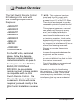
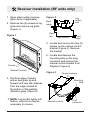
Owner’s Manual Model WRCPF-KIT IMPORTANT SAFETY INFORMATION: Always read this manual first before attempting to install or use this device. For your safety, always comply with all warnings and safety instructions contained in this manual to prevent personal injury or property damage. To view the full line of Dimplex products, please visit www.dimplex.com 7209110100R03 Table of Contents Welcome & Congratulations . . . . . . . . . . . . . 3 Product Overview. . . . . . . . . . . . . . . . . . . . . . 4 Receiver Installation (BF units only) . . . . . . . 5 Wall Control Installation . . . . . . . . . . . . . . . . 7 Initialization . . . . . . . . . . . . . . . . . . . . . . . . . 14 Operation. . . . . . . . . . . . . . . . . . . . . . . . . . . 15 Warranty . . . . . . . . . . . . . . . . . . . . . . . . . . . 20 ! NOTE: Procedures and techniques that are considered important enough to emphasize. CAUTION: Procedures and techniques which, if not carefully followed, will result in damage to the equipment. Warning: Procedures and techniques which, if not carefully followed, will expose the user to the risk of fire, serious injury, or death. 2 www.dimplex.com Welcome & Congratulations Thank you and congratulations for choosing to purchase a Wall Switch Remote Control Kit from Dimplex, the world leader in electric fireplaces. Please carefully read and save these instructions. CAUTION: Read all instructions and warnings carefully before starting installation. Failure to follow these instructions may result in a possible electric shock, fire hazard and will void the warranty. NO NEED TO RETURN TO THE STORE Questions with operation or assembly? Require Parts Information? Product Under Manufacturer’s Warranty? Contact us at: OR www.dimplex.com/customer_support For Troubleshooting and Technical Support Toll-Free 1-888-DIMPLEX (1-888-346-7539) Monday to Friday 8:00 a.m. to 4:30 p.m. EST Please have your model number and product serial number ready. (See above) 3 Product Overview The Wall Switch Remote Control Kit is designed to work with the following Dimplex electric fireplaces: •BF33STP •BF33DXP •BF39STP •BF39DXP •BF45DXP •BFSL33 •BLF50 •DF3033ST •DFG3033BLK ! NOTE: This equipment has been tested and found to comply with the limits for Class B digital device, pursuant to part 15 of the FCC Rules. These limits are designed to provide reasonable protection against harmful interference in a residential installation. This equipment generates, uses and can radiate radio frequency energy and, if not installed and used in accordance with the instructions, may cause harmful interference to radio or television reception, which can be determined by turning the equipment off and on, the user is encouraged to try to correct the interference by one or more of the following measures: · Reorient or relocate the receiving antenna. For the BF units, mentioned above, follow the Remote Receiver control installation instructions starting on page 5. · Increase the separation between the equipment and the receiver. For fireplace models BFSL33, BLF50, DF3033ST and DFG3033, the pre-installed remote receiver in these models is compatible with the Wall Switch Remote Control. The Remote Receiver and bracket contained in this kit will not be required, proceed directly to the Wall Control Installation on page 7. · Consult the dealer or an experienced radio/TV technician for help. 4 · Connect the equipment into an outlet on a circuit different from that to which the receiver is connected. Operation is subject to the following two conditions: (1) this device may not cause interference and; (2) this device must accept any interference, including interference that may cause undesired operation of the device. www.dimplex.com Receiver Installation (BF units only) 1.Open steel curtain (remove glass doors if applicable). 2.Remove two (2) screws on log grate and remove log grate (Figure 1). Figure 1 Figure 2 Log ember bed Back ledge Rear tab Side section Front edge 4.Locate and remove the two (2) screws on the manual control bracket (Figure 3). Remove the bracket. Screws Manual Controls 5.Locate and depress the mounting tabs on the plug connector and remove the manual control bracket from fireplace (Figure 3). Figure 3 Screw locations 3.Pull front edge of plastic ember bed grate up and forward until rear tab releases from the ledge located at the bottom of the partially reflective glass (Figure 2). ! NOTE: Log set fits tightly into firebox, some force may be necessary to remove. Mounting tabs Manual controls Plug connector 5 Receiver Installation (BF units only) 6.Locate the plastic 9-pin plug in the bottom corner of the fireplace where the manual controls were plugged in to. 7.Insert the plug connector from the remote control bracket (Figure 4) into plastic plug inside the fireplace. Figure 4 Remote Control ledge (Figure 2) and the logs are resting against the partially reflective glass. 11.Replace log grate using two (2) screws previously removed in step 2. Antenna Plug Connector 8.Run black antenna wire under remote bracket and ensure all wiring is placed such that it does not interfere with reassembly. 9.Install the two (2) screws removed in step 4 into the remote control bracket and attach it to the fireplace. 10.Replace the log set by inserting front edge and pushing the back down until rear tab snaps under back 6 www.dimplex.com Wall Control Installation ! NOTE: All electrical wiring must comply with all national and local electrical codes and regulations. Always use a qualified and licensed electrician should you have any questions or concerns for all wiring work. ! NOTE: The Wall Switch Remote Control is made to fit standard Decora style faceplates. Due to material inconsistencies of individual faceplates, it may be necessary to remove the faceplate for operations such as changing batteries. Site Selection for Installation Although this Wall Switch Remote Control can operate on battery power or by hard wire installation, a convenient and accessible location should be chosen. The range of the Wall Switch Remote Control is approximately 50 feet (15 m). Installation requires the use of a standard device box and should the hard wire installation method be chosen, a location near an available 24V~ power source should be considered. WARNING: Electrocution or other bodily harm and property damage can occur if a live wire is touched or damaged during installation. Always consult electrical schematics for the installation location of all wiring or consult a qualified and licensed electrician before you begin. Installation Required Tools and Hardware: • Flat head screwdriver • Wire cutters / strippers • Two (2) wire nuts for 22 AWG wire • Standard wall device box with minimum depth of 2.5 inches (6.35 cm) • 24V~ Power supply (for hard wired power installation if applicable) Battery Powered Installation 1. Remove the Wall Switch Remote Control and installation hardware from its package. 7 Wall Control Installation 2. Release the Controller from its Outer Housing by pushing the front face into the Outer Housing until you hear a click. This will release the pushlock latches and allow the Controller to be removed from the Outer Housing (Figure 5). Figure 5 3. Open the Battery Compartment as shown in Figure 6 and remove the Insulating Strip as shown in Figure 7. Figure 7 Outer Housing Insulating Strip 4. Replace the battery compartment cover. Controller Figure 6 Battery Compartment 8 5. Reinsert the Controller back into the Outer Housing by realigning the tracks on the top and bottom of the unit with the guides inside the Outer Housing. Push the Controller in until you hear the pushlock latches click (Figure 8). 6. Slide the Controller and Outer Housing assembly into a standard device box and fasten with the two (2) flat www.dimplex.com Wall Control Installation to complete the installation and to blend the installation in with your choice of decor. Figure 8 Controller Tracks Hard Wired Power Supplied Installation Before starting this installation, it is helpful to initialize the Wall Switch Remote Control with your firebox (see Initialization section). Guides Outer Housing • Installed standard wall device box with a minimum depth of 2.5 inch (6.35 cm). Figure 9 Controller • A 24V~ power source leading to the device box. Possible sources could be a 24V~ doorbell circuit or a Class 2 24V~ transformer. Wall Box Outer Housing Flat head screws (supplied) head screws (supplied) as shown in Figure 9. 7. Attach your choice of Decora style faceplate (not supplied) You should have the following items ready and prepared: • The 24V~ wire leads coming into the device box should have between 4 and 6 inches (10-15 cm) of slack left inside the box to allow for ease of installation and/or servicing. • You may also leave the supplied AAA batteries in the Controller. There is an internal electronic bypass that will draw on the hard wired power source before the batteries. 9 Wall Control Installation 1. Unpack the Wall Switch Remote Control and all hardware from its package. 2. Release the Controller from its Outer Housing by pushing the front face into the Outer Housing until you hear a click. This will release the pushlock latches and allow the Controller to be removed from the Outer Housing (Figure 5). of the two holes located on the wire lead storage compartment cover (make sure orientation is as shown as in Figure 11). Figure 11 3. Push the wire lead storage compartment cover on the back of the Control towards the right (as shown), and remove (Figure 10). Figure 10 5. Replace the wire lead storage compartment cover on the Controller with wire leads fed through and exposed. 6. Feed the two wire leads from the Controller through the two holes in the back of the Outer Housing as shown in Figure 12. 4. Uncoil the two wire leads and feed each of them through one 10 7. Gently pull the wire leads through while pushing the Controller into the Outer Housing until you hear the push lock latches click, locking the Controller in place (Figure 13). www.dimplex.com Wall Control Installation Figure 12 Controller Figure 13 Outer Housing Locking Screw Option (Figure 14) To prevent tampering, damage, and theft, it is suggested to install the locking screws. Once installed, the locking screws will prevent the Controller from being released from the Outer Housing without being removed first from the device box in the wall. ! NOTE: A Philips head screwdriver will be required for this step. Figure 14 Locking screws Outer Housing 8. Using the wiring diagram in Figure 15 as a guide, make the appropriate wire connections. 11 Wall Control Installation Figure 15 Ensure each of the two Controller lead wires are connected to separate Low Voltage 24V~ only wires. Controller wire leads Low Voltage 24V~ power source ONLY Figure 16 Flat Head Screws (supplied) 12 www.dimplex.com Wall Control Installation ! NOTE: Wire leads are not polarized due to the nature of this device. 9. Coil excess wiring to the back of the device box and insert the Controller and Outer Housing into the device box (Figure 16). Fasten with two supplied flat head screws. 10.Attach your choice of Decora style faceplate (not supplied) to complete the installation and to blend the installation in with your choice of decor. 11.Initialize the sender with the receiver installed in your fireplace. 13 Initialization After installation, locate the section which applies to your specific model of fireplace and follow the steps for remote control initialization and if required, re-initialization. Refer to your fireplace's owner's manual to locate manual or other controls as needed. BF Models Using the Included Receiver Module 1. Ensure that power is supplied through main service panel. 2. Inside the fireplace, locate the toggle switch on the manual controls and set to “Remote” (Figure 17-C). Figure 17 A B 4. Press any button on the Wall Switch Remote Control within that 10 seconds. BLF50 Models 1. Ensure that power is supplied through main service panel. 2. Inside the fireplace, turn Main On/Off Switch to Off (Figure 18-A) and wait 10 seconds. 3. Move the Three Position Switch (Figure 18-B) to the “ REMOTE ” position. Figure 18 C B A C BLF50 Manual controls 4. Turn Main On/Off Switch to On. D E F 3. Press and hold the On button on the manual controls (Figure 17-A) for five (5) seconds. The Level 1 Indicator Light (Figure 17-D) will then flash for 10 seconds. 14 5. Press and hold the Manual Control Button marked “ I ” (Figure 18-C) for five (5) seconds. After five (5) seconds, there is a 10 second window to press any button on the remote control. 6. Press any button on the Wall Switch Remote Control within that 10 seconds. www.dimplex.com Initialization DF3033ST and DFG3033 Models 1. Ensure that power is supplied through main service panel. 2. Ensure the Main On/Off Switch located in the switch box on the fireplace in the upper right On hand corner is in the position (Figure 19A). Figure 19 C B A 3. Set the 3 Position Manual Control (Figure 19B) to the Remote position (left position). 4. Press and hold the Initialization Button on the unit (Figure 19C). 5. While holding the Initialization Button, press any button on the Wall Switch Remote Control. 6. Release the Initialization Button and button pressed on the Control, sender is initialized with the fireplace. DF3033ST / DFG3033 Manual controls Operation Manual Controls The following instructions will cover the operation of the manual controls installed with the receiver board contained with this kit (BF unit installations). For the operation of manual controls for other installations (BLF50, DF3033ST and DFG3033), please consult your Owner's Manual for those specific models. The fireplace can be controlled with switches located on the receiver as shown in Figure 20. ! NOTE: Firebox must have the Main On/Off and mode selector switch in the full on position for all features to work properly. 15 Operation Figure 20 A B C D A. On Button Pressing this button toggles sequentially through the three levels of the fireplace. Pressing once activates Level 1 - flame effect only, twice activates Level 2 - flame effect and Purifire™, three times activates Level 3 - flame effect, Purifire™ and heat. B. Off Button Pressing this button at any time will shut the unit off. • OFF (center): Makes the unit inoperable. • MANUAL (top): All functions of the fireplace are controlled by the On and Off buttons as described above (A, B). • REMOTE (bottom): All functions of the fireplace are controlled by the Wall Switch Remote Control. D. LED Indicators Depicts which of the three (3) levels the fireplace is currently operating at: Level 1 - flame effect only; Level 2 - flame effect and Purifire™; Level 3 - Flame effect, Purifire™ and heat. ! NOTE: The third LED (Level 3) on receiver board will always be illuminated when the Manual Selection Switch is set to REMOTE. The only time that the LED is turned off is when the thermostat is set to “Heat Off”. C.Manual Selection Switch Switches the operation of the fireplace between the different modes of the fireplace: 16 www.dimplex.com Operation Wall Switch Remote Control 6 7 5 1 2 8 9 10 11 12 13 4 1. 2. 3. 4. 5. 6. 7. Display Room Temperature Set Temperature Flame Effect Purifire™ Heat Off Indicator Function Lock Indicator RF Code Function Indicator 3 14 Operation 8. Set Temperature Down 9. Set Temperature Up 10. Flame Off 11. Flame On 12. Purifire™ Off 13. Purifire™ On 14. Low Battery Indicator 17 Operation 1. Room Temperature Displays current ambient temperature in the room. 2. Set Temperature Displays and controls the heater to the temperature at which the thermostat is currently set to. Press 8 to lower the thermostat and press 9 to raise the thermostat. Pressing both 8 and 9 together will toggle between Celsius and Fahrenheit. 3. Flame Effect Icon The flame icon will flicker if and when the Flame Effect is turned on. Press 11 to turn the Flame Effect on, and press 10 to turn the Flame Effect off. 4. Purifire™ Icon The display arrows for the Purifire™ will cycle when turned on. Press 13 to turn the Purifire™ function on, and press 12 to turn Purifire™ off. those units with the Purifire™ installed. 5. Heat Off Indicator This function manually overrides the thermostat control and prevents the fireplace’s heater from coming on. To do this, press 8 to decrease Set Temperature to any temperature below 0o C or 32o F. To reactivate heat from “HEAT OFF” setting, press 9 to increase the thermostat Set Temperature. The Set Temperature will be displayed starting at 21o C (70o F), replacing the “HEAT OFF” icon. 6. Function Lock Indicator Enabling this function will lock out the Wall Switch Remote Control so as to prevent the current settings from being changed. To Enable, press 8, 9, and 10 sequentially. To disengage, press 8, 9 and 10 sequentially again. The Indicator icon will be displayed when enabled. ! NOTE: The Purifire™ function on this device will control only 18 www.dimplex.com Operation 7. RF Code Function and Change Procedure In the event that the Wall Switch Remote Control does not work properly with the receiver due to interference from additional wireless signals, this function will allow the RF code to be changed. To enable this function, press 9 and 12 together. “COD” will appear on the display for five (5) seconds and the RF code will change automatically. Repeat procedure as needed to find a code that operates the fireplace without interference. Re-initialization of the Wall Switch Remote Control will need to take place with receiver after a new code has been activated. See initialization instructions on page 14. 14.Low Battery Indicator When displayed, the indicator will signal that the batteries are low and should be replaced. To further extend battery life, the LED backlighting is turned off when the Low Battery Indicator is displayed. Other Functions 6 Hour Sleep Timer This feature ensures all functions are turned off six hours after any last button has been pressed. To turn this feature on and off press 9, 11, 10, and 8 sequentially. When activated, “6 Hr” will display for 5 seconds while the rest of the LCD remains blank. For the duration of the 6 hour delay, all functions remain working until the 6 hour time delay runs out. The Set Temperature and Room Temperature icons will alternately display their settings and the “6 Hr” icon display. After 6 hours have passed and all functions are turned off, “6 Hr” will flash until any button is pressed. ! NOTE: If any button is pressed while this function is enabled, the 6 hour timer will start over for another 6 hour period. If / when deactivated, “- Hr” will display for five (5) seconds. 19 Warranty This Dimplex Wall Switch Remote Control is warranted against defects in workmanship and materials for two years from date of sale. This warranty does not apply to damage from accident, misuse, or alteration, nor where the connected voltage is more that 5 % above the nameplate voltage, nor to equipment improperly installed or wired or maintained in violation of the instruction sheet. This limited warranty applies only to purchases made in any province of Canada except for Yukon Territory, Nunavut, or Northwest Territories or in any of the 50 States of the USA (and the District of Columbia) except for Hawaii and Alaska. This limited warranty applies to the original purchaser of the product only and is not transferable. No other written or oral warranty applies. No employee, agent, dealer or other person is authorized to give any warranties on behalf of Dimplex. The customer shall be responsible for all costs incurred in the removal or reinstallation and shipping of the product for repairs. Within the limitations of this warranty, inoperative units shall be returned to the nearest Dimplex authorized service center, and we shall repair or replace, at our option, at no charge to you with return freight paid be Dimplex. It is agreed that such repair or replacement is the exclusive remedy available from Dimplex and that DIMPLEX IS NOT RESPONSIBLE FOR DAMAGES OF ANY KIND, INCLUDING INCIDENTAL AND CONSEQUENTIAL DAMAGE. Some States do not allow the exclusion or limitation of consequential damages, so the above exclusion or limitation may not apply to you. This warranty gives you specific legal rights and you may also have other rights which vary from state to state. Dimplex North America Limited 1367 Industrial Road Cambridge ON Canada N1R 7G8 © 2012 Dimplex North America Limited 20 www.dimplex.com