1
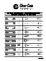
PARTY-LINE
INTERCOM
SYSTEM INSTALLATION
MANUAL
Clear-Com System Installation Manual
TABLE OF CONTENTS
Introduction . . . . . . . . . . . . . . . . . . . . . . . . . . . . . . . . . . . . . . . . . . . . . . . . . . . . .
The Clear-Com Concept . . . . . . . . . . . . . . . . . . . . . . . . . . . . . . . . . . . . . . . . . .
Power Distribution and Short Circuit Protection . . . . . . . . . . . . . . . . . . .
Installing an Intercom System . . . . . . . . . . . . . . . . . . . . . . . . . . . . . . . . . . . .
1
1
2
3
Single-Channel System . . . . . . . . . . . . . . . . . . . . . . . . . . . . . . . . . . . . . . . . . . . . . . . . . . . . . . . . 3
Multi-Channel System . . . . . . . . . . . . . . . . . . . . . . . . . . . . . . . . . . . . . . . . . . . . . . . . . . . . . . . . . . 4
Crosstalk Considerations in a Multi-Channel System . . . . . . . . . . . . . . . . . . . . . . . . . . . 4
Intercom Cable Considerations
................................................ 5
Installing the Stations . . . . . . . . . . . . . . . . . . . . . . . . . . . . . . . . . . . . . . . . . . . . 6
Connections . . . . . . . . . . . . . . . . . . . . . . . . . . . . . . . . . . . . . . . . . . . . . . . . . . . . . . . . . . . . . . . . . . . 6
Configuring Clear-Com Products to Work Together . . . . . . . . . . . . . . . . . . . . . . . . . . . . . 8
Typical Applications . . . . . . . . . . . . . . . . . . . . . . . . . . . . . . . . . . . . . . . . . . . . . 10
Cable or School Television Studio . . . . . . . . . . . . . . . . . . . . . . . . . . . . . . . . . . . . . . . . . . . . . 10
Theatre 1 . . . . . . . . . . . . . . . . . . . . . . . . . . . . . . . . . . . . . . . . . . . . . . . . . . . . . . . . . . . . . . . . . . . . . 12
Theatre 2 . . . . . . . . . . . . . . . . . . . . . . . . . . . . . . . . . . . . . . . . . . . . . . . . . . . . . . . . . . . . . . . . . . . . . 14
ENG/EFP Truck . . . . . . . . . . . . . . . . . . . . . . . . . . . . . . . . . . . . . . . . . . . . . . . . . . . . . . . . . . . . . . . 16
System Checkout . . . . . . . . . . . . . . . . . . . . . . . . . . . . . . . . . . . . . . . . . . . . . . . 17
Final Tests . . . . . . . . . . . . . . . . . . . . . . . . . . . . . . . . . . . . . . . . . . . . . . . . . . . . . . . . . . . . . . . . . . . . 17
Troubleshooting . . . . . . . . . . . . . . . . . . . . . . . . . . . . . . . . . . . . . . . . . . . . . . . . 18
Glossary . . . . . . . . . . . . . . . . . . . . . . . . . . . . . . . . . . . . . . . . . . . . . . . . . . . . . . . . 20
Clear-Com System Installation Manual
INTRODUCTION
Congratulations on choosing Clear-Com products. Clear-Com was established in 1968 and remains the
market leader in providing intercom for entertainment, educational, broadcast and industrial applications. The ruggedness and high build-quality of Clear-Com products is the industry standard. In fact,
many of our original beltpacks and Main Stations are still in daily use around the world.
We recommend that you read through this manual completely to better understand how to install your
intercom system. Please pay particular attention to the section on system wiring, as improper wiring
detracts from the performance of the system or causes system failure. If you encounter a situation or
have a question that this manual does not address, contact your dealer or call Clear-Com direct at the
factory. Our applications support and service people are standing by to assist you. Thank you for selecting Clear-Com for your communications needs.
THE CLEAR-COM CONCEPT
Clear-Com is a closed-circuit intercom system that consistently provides high-clarity communication in
both high-noise and low-noise environments. A basic system consists of a single- or multi-channel
Power Supply or Main Station connected to various single- or multi-channel Remote Stations, such as
beltpacks and loudspeaker stations.
Clear-Com is a distributed amplifier system; each Main or Remote Station houses its own microphone
preamplifier, headset or speaker power amplifier, and signaling circuitry. Stations bridge the intercom
line at a very high impedance (more than 10 kOhms), and place a minimum load on the line. The
audio level always remains constant, and does not fluctuate as stations leave and join the system.
Low-impedance mic input lines (200 Ohms) and specially designed circuitry make Clear-Com channels
virtually immune to RFI and dimmer noise.
Clear-Com stations are interconnected with two-conductor, shielded microphone cable (or individually
shielded multi-pair cable as required). Portable stations are connected with 2 conductor cables with
3-pin XLR connectors. One wire, connected to pin 2, carries the DC power (30 volts) from a Main Station or Power Supply to all Remote Stations. The other wire, connected to pin 3, carries the 2-way (duplex) audio information. The shield, connected to pin 1, acts as a common ground. One termination
per channel is needed throughout the intercom network, and is usually located in the Main Station or
Power Supply.
Clear-Com Main Stations, Power Supplies and certain Remote Stations each have an auxiliary program input with its own volume control, which allows an external audio source to be fed to the intercom
system.
Visual Signal Circuitry (Call Lights), a standard feature on all Main and Remote Stations, allows the
user to attract the attention of operators who have removed their headsets. Certain stations also have
an audible Tone Alert feature which can be useful for this purpose.
Clear-Com manufactures a wide variety of both portable and fixed-installation units. All are compatible
with each other. Clear-Com intercom systems can also interface with other communication systems
and devices.
1
Clear-Com System Installation Manual
POWER DISTRIBUTION AND SHORT CIRCUIT PROTECTION
A Main Station or Power Supply is the heart of an intercom system. It has special features which are
not found in traditional designs. It must supply low-noise 30 Volt DC current to multiple intercom lines.
It must continue to operate in adverse conditions such as low AC line voltage, momentary shorts on the
DC power lines to the stations, and excessive peak loads during power-on conditions.
Use the chart on this page to determine how many Speaker Stations and Beltpacks can be powered in
varying combinations by a Main Station or Power Supply. Additional power supplies can be connected
for additional power capability if required by the application. The current requirements of Clear-Com
Remote Stations and Beltpacks vary with model and use. A station which is simply '"on" and not being
used may draw only a small amount of current. Contact your dealer or Clear-Com if you require further
assistance in determining the overall current requirements of your system.
20
15
Number of
Speaker
Stations
Overload
Acceptable
10
5
for
2 Amp Supplies
Acceptable
for
1 Amp Supplies
5
10
15
20
25
30
35
40
45
50
55
60
Number of Beltpacks
For example, a 2 ampere Main Station will power 60 Beltpacks or 20 Speaker Stations. The total current capability of a Main Station or Power Supply is split between its channels. Short circuits and overloads on either channel will not damage a Main Station or Power Supply. It will simply cut power off to
each channel which exceeds its maximum current or which causes the system maximum to be exceeded. A channel which is within its maximum current rating will not be affected by another channel
being automatically cut.
Within 15 seconds of automatically cutting power to an overloaded channel, the Main Station or Power
Supply will attempt to turn power on again. This allows momentary short or overload conditions to
clear automatically. Red Short LEDs corresponding to each channel light if power is cut, indicating
which channel is affected. This indication will assist in locating the shorted or overloaded channel.
Shorts are generally caused by miswiring or damaged cables. Overloads are generally caused by connecting too many beltpacks and stations to a channel.
2
Clear-Com System Installation Manual
INSTALLING AN INTERCOM SYSTEM
When considering how to install and wire an intercom system, several factors must be taken into account. These include the number of stations, the length of the cable runs and whether single or multiple channels are required. If multi-channel stations are connected with multi-pair cables, then crosstalk
becomes an important issue. Crosstalk is not a factor with single-channel systems or multi-channel
systems where each channel is run on its own individual cable to single-channel Remote Stations.
While the physical considerations include ease of installation, type of cabling, station location, etc., the
electrical considerations are concerned primarily with the capacitance between conductors on the intercom line, and the DC resistance in the ground return of the intercom line.
NOTE: PIN 1 and the shell of the XLR plug on the interconnect cables should NOT be
connected together.
Excessive resistance in the conductors of the cable results in a loss of sidetone null at Remote Stations, and some overall loss of level. Excessive resistance in the ground conductor or shield greatly
increases crosstalk between channels. This can significantly affect the performance of multi-channel
systems.
Single-Channel System
In a single-channel system, there are two general methods of wiring Remote Stations to the Power
Supply. Any one method may be used exclusively in a small system, and both may used in various
combinations for a larger system.
1
Daisy Chain: Remote stations are wired from one station to the next and so on along each
line connected to a Main Station. This requires the least amount of cable, but may be impractical due to the system layout. Also, if a break occurs in the line, all stations down line of the
break will be disconnected from the party line.
2
Hub, Star or Home Run: Each Remote Station is wired directly back to a Main Station or to a
split of a line wired directly to a Main Station.
Channel A
Channel A
3
Clear-Com System Installation Manual
Multi-Channel System
In a multi-channel system where each channel is run on its own cable and connected only to single
channel Remote Stations as in the following diagram, there are no crosstalk issues because the channels do not share a common ground. Consult the table in the next section for cable recommendations.
Channel C
Channel B
Channel D
Channel A
It is also important to centrally locate the multi-channel Main Station or Power Supply containing the
termination. Crosstalk does not exist at the termination point, but can increase in proportion to the
length of the wiring to multi-channel stations. If the termination is centrally located and the wiring
length guidelines in the following section are adhered to, then crosstalk will be at a minimum.
Crosstalk Considerations in a Multi-Channel System
In a multi-channel system where multiple channels are run from a Main Station to a Remote Station as
in the following diagram, crosstalk can be an issue. This is because the channels will share a common
ground at both ends of the cable run.
4-Channel
Remote
Station
4-Channel
Main Station
or Power
Supply
A
2
1
B
2
3
2
3
2
3
1
Ch. B Audio
Ch. B Audio
Gnd*
Shield**
Ch. C Audio
Shield**
Ch. C Audio
Gnd*
1
D
Ch. A Audio
Drain wire Gnd
Ch. A Audio
Drain wire Gnd
Gnd*
1
C
Power
Power
3
Shield**
Ch. D Audio
Gnd*
Shield**
Gnd*
* = Spare Wire used for Gnd
** = If the shields from individual
pairs are brought out separately,
they must also be connected to
Pin 1.
4
Shield**
Ch. D Audio
Gnd*
Shield**
A
2
3
1
B
2
3
1
C
2
3
1
D
2
3
1
Clear-Com System Installation Manual
When multiple channels are fed to Remote Stations, the amount of crosstalk between channels is proportional to the DC resistance of the ground return path back to the channel terminations. To minimize
this crosstalk between channels when running more than one channel in a multi-pair cable, keep the
DC resistance of the ground return as low as possible. Ideally, this should be less than 2 Ohms. This
can be achieved as follows:
Keep cable runs under 500 feet. If a longer cable run is unavoidable and approaches 1000 feet or
more, make sure the appropriate lone line option switches or jumpers are set in the stations. Refer
to the individual station manuals for further information.
Use a cable whose common shield has a low DC resistance.
Connect unused cable wires of a multi-pair cable to the Pin 1 shield.
NOTE: All multi-pair cables must have individually shielded pairs.
Clear-Com recommends the Belden 1800 Series of multi-pair cables. They offer a common shield with
a low DC resistance in addition to individual shields on each pair.
The performance of a Clear-Com system depends upon the use of Clear-Com or Clear-Com approved
compatible headsets. Use of headsets other than these can induce crosstalk into a multi-channel system through the headset cable. Clear-Com also recommends against the use of headset extension cables or headset "Y" cables, as they will increase crosstalk into a multi-channel system.
Intercom Cable Considerations
The Clear-Com intercom line is intended to run on one shielded cable pair per intercom channel. One
conductor carries audio, and the other conductor carries the DC power for Remote Stations. The shield
serves as the ground return for the audio and power conductors. When choosing interconnect cable,
keep the following considerations in mind:
Keep cable runs under 500 feet. The DC resistance of the ground or common conductor affects
crosstalk. For permanent installation runs longer than 500 feet, do not use wire smaller than 20
gauge. The capacitance of the interconnect cable affects system frequency response and sidetone
stability. Total capacitance should not be greater than 0.25 uF.
Ground Isolation: The Pin 1 ground connection of each XLR connector must be isolated from the
chassis. Pin 1 should not be connected to the shell of the XLR connector.
Multi-pair Cable: Individually shielded multi-pair cable is acceptable for use in multi-channel systems. For crosstalk considerations the shields must be tied together on both ends of the cable to
produce the lowest possible DC resistance path for the ground return.
Suggested Cable Types: The following chart lists the specifications of various BELDEN cables:
BELDEN SHIELDED CABLES
Trade
#
# of
Pairs
AWG &
Stranding
Nom. O.D. Nom. Cap.
(inch)
(pF/ft)
Shield
Nom. D.C.R.
(Ohms)
8412
1
20 (26x34)
0.268
30
5000
Portable
8762
1
20 (7x28)
0.196
27
5000
Permanent (short)
8760
1
18 (16x30)
0.222
24
5000
Permanent (long)
1814A
2
22 (7x30)
0.319
31
3.9 Ω/M'
1500
Permanent
1815A
4
22 (7x30)
0.384
31
3.9 Ω/M'
1500
Permanent
1817A
8
22 (7x30)
0.503
31
3.6 Ω/M'
1500
Permanent
1818A
12
22 (7x30)
0.889
31
3.4 Ω/M'
1500
Permanent
* for better than 50 dB channel crosstalk
5
Max.* Cable
Run (ft)
Recommended
Application
Clear-Com System Installation Manual
Portable Installation Cable: Practical cable for portable system interconnections is flexible, twoconductor, shielded microphone cable. We suggest using BELDEN #8413 (24 Gauge). For runs
longer than 500 feet use a 20 gauge cable or larger (BELDEN #8412).
Permanent Installation Cable: Vinyl-jacketed shielded pair is the cable of choice for permanent
installations. Placing the cable in conduit is recommended but not necessary.
INSTALLING THE STATIONS
First, choose the location for the Main Station or Power Supply. These units require access to AC
power. They should be located away from other equipment that generates excessive amounts of heat.
Also, choose locations for each Remote Station and Speaker Station. Choose general locations and
areas of use for the beltpacks. Determine the locations for other Clear-Com equipment which will connect to the intercom lines. The choice of location will depend upon and often define the wiring scheme.
It is very helpful to create a drawing showing where each component will be located as well as where
the wiring will run.
Connections
The following sections describe the connections provided on the intercom stations:
Intercom Line Connection: The rear panel of Main Stations, Power Supplies, Remote Stations,
and other stations contain between one and three 3-pin male XLR connectors for each intercom line.
These connectors are wired in parallel. Any single-channel station or channel of a multi-channel
station connected on a line plugged into Channel A of the a Main Station will be "party-lined" with all
the other stations on that channel. In a multi-channel system, the goal is to assign specific people
to the correct group, i.e. the other people they need to be in contact with the most. This is particularly important when the party line users are on a single-channel beltpack or station; less so if they
are on multi-channel stations. The pinout of the intercom connectors is as follows:
Pin 1 --- Ground (Shield)
Pin 2 --- Power (+30 VDC)
Pin 3 --- Audio
Line Termination: The fundamental concept of Clear-Com Party-Line intercom is that all channels
are terminated in one location, preferably at a Main Station or Power Supply.
CAUTION: All intercom lines must be terminated. Care must be taken not to
'"double-terminate" a line. All unused intercom lines must also be terminated.
Switching of the channel terminations ON and OFF is done with switches or jumpers on the Main
Station. In most systems, the terminations should be in the ON position (default setting). ClearCom Power Supplies also provide switch-selectable termination networks on all intercom lines. Refer to the User manual for the specific Main Station or Power Supply for the exact location. It is up
to the user to ensure that the terminations are set correctly. An unterminated line will cause excessive levels, possible oscillation of line drivers, and squealing in the headsets. An intercom line with
double or multiple terminations will cause low levels and the inability to null the headsets.
The termination switches on a Main Station should be set to the OFF position only if the channel is
terminated by another Main Station or Power Supply in the system. If there are no other Main
Stations or Power Supplies terminating the line, the termination switch on each channel of
the Main Station should be switched to ON.
Headset Connector: The headset connector is located on the front panel of all stations. ClearCom headsets are recommended, but others can be used if they meet the following requirements:
Mic Type --- Dynamic; 150 to 250 ohms impedance; -55 dB output level
Headphone --- Dynamic; 50 to 2000 ohms impedance
6
Clear-Com System Installation Manual
The wiring of the headset is to be as follows:
Pin 1
Pin 2
Pin 3
Pin 4
---------
Mic common
Mic hot
Headphone common
Headphone hot
The mic and headphone wiring in the headset cord must be individually shielded. Do not connect
Pins 1 and 3 together. Headset extension cords or headset "Y" cables are not recommended because they will increase crosstalk between channels.
Panel Mic Connector: Clear-Com recommends the GM-9 and GM-18 plug-in panel microphones
for use with all stations having a panel mic connector. The GM-9 is 9 inches long and the GM-18 is
18 inches long. The microphone is an electret type. The 1/4 inch phone jack on the microphone
mates with the Panel Mic receptacle on the front panel.
To install a GM-9 or GM-18 microphone, use the following steps:
1
Check the set screw in the mic mounting flange to make sure it is clear of the threads in
the bushing.
2
Screw the microphone into the bushing hand tight.
3
Set the set screw on top of the bushing to lock the microphone in place.
Hot Mic Out / IFB System: Some Main and Remote Stations have an interface to the External
Line In jack on Clear-Com's IFB System. This connection is a 1/4 inch phone jack on the rear
panel. It provides a 0 dBv output signal from the selected headset or panel microphone on the station. It connects using a standard 2-wire and shield stereo 1/4 inch plug-to-plug cable such as the
Clear-Com P/N 73016501 (18 inch) or P/N 73016502 (5 foot). It allows the station's microphone to
be used to cue talent through the IFB System. A control signal sent into this connector from the IFB
System can optionally disconnect the station's microphone from the intercom line(s). The jack is
wired as follows:
Ring --- Ext. IFB Control Signal Input
Tip --- Hot Mic Audio Output
Sleeve --- Ground (Shield)
Stage Announce Output: Some Main and Remote Stations have a 3-pin XLR male connector on
the rear panel to feed into a studio PA. Pressing the Announce button on the front panel places the
audio from the selected headset or panel microphone on the rear panel connector. Optionally,
pressing the Announce button can also disconnect the selected headset or panel microphone from
the intercom line(s). This option is controlled by the Interrupt Announce option switch. Simultaneously, if the program audio feed to the Announce Output is enabled, it is interrupted by the announcement. Program audio feed to the Announce Output is selected by setting a jumper on the
Main board to the ON position. The pinout of the Announce Out connector is as follows:
Pin 1 --- Ground (Shield)
Pin 2 --- - Signal
Pin 3 --- + Signal
The audio output is balanced and transformer isolated. It has a 600 ohm impedance and a nominal
output level of 0 dBv. A shielded twisted pair cable should be used in the cable wired to this
connector.
Relay Out: On Main and Remote Stations with an Announce button, a dry set of relay contacts is
provided through a 1/4 inch jack or screw terminals on the rear panel. These contacts can activate
an external device such as a PA amplifier to another room. The contacts are rated for 2.0 Amps at
24 VDC. If screw terminals are provided on the Main Station, their connections are labeled N/C, C
and N/O. The 1/4 inch jack is wired as follows:
7
Clear-Com System Installation Manual
Ring --- Normally Closed Contact --- N/C
Tip --- Common Contact --- C
Sleeve --- Normally Open Contact --- N/O
Program Input: A 3-pin XLR female connector on most Main Stations and Power Supplies provides the program input to the intercom system. The Program Input accepts a balanced or unbalanced line-level audio signal from -20 dBv to +10 dBv. There is an option to feed program audio to
the Announce Output. This is selected by setting a jumper on the Main board to the ON position.
When this option is selected, a 0 dBv signal on the Program Input will produce a 0dBv signal on the
Announce Output.
The pinout of the Program Input connector is as follows:
Pin 1 --- Ground (Shield)
Pin 2 --- + Signal
Pin 3 --- - Signal
External Speaker: Some Main Stations provide an 8 ohm external speaker output through a 1/4
inch jack.
Auxiliary Connector: Some Main Stations provide a DB-15 type Auxiliary connector on the rear
panel. This allows connection to a variety of devices, depending upon the capabilities and features
of that particular Main Station. Refer to the Main Station User Manual for further details on the connections provided.
AC Power Connection: An IEC type 320 connector is provided on most Main Stations and Power
Supplies to interface to the appropriate AC power cord to be used. Refer to the chart on the inside
back cover of this manual. Main Stations and Power Supplies can either be switched between 115
or 230 VAC operation or will automatically adjust to voltages from 90 to 240 VAC at 50 or 60 Hz.
Consult the User Manual for information on the particular unit.
Configuring Clear-Com Products to Work Together
Clear-Com Intercom Systems are designed to integrate with many other Clear-Com products. The following sections describe some frequently used configurations. Most of these configurations involve the
use of Clear-Com's versatile Call signal. This signal travels silently through the intercom wiring and is
often used to get the attention of operators who have removed their headsets. However, as the following descriptions show, it can also be used to control a variety of functions.
TW-40 Two-Way Radio Interface
It is often important to link walkie-talkies into an intercom system to extend communication to remote
persons. The TW-40 Two-Way Radio Interface connects between an intercom line and a variety of
walkie-talkies, using one walkie-talkie as a base station. Refer to the TW-40 Instruction Manual for details describing the connection of the TW-40. To interface with the TW-40, the option switches of the
Main or Remote Station must be set as follows:
Enable the Momentary Talk option switch or jumper on the appropriate channel of the Main or Remote Station. Refer to the User Manual for the Main or Remote Station to locate this switch or
jumper. This will cause the Talk button to have a momentary only action and not latch.
Enable the Call on Talk option switch or jumper on the appropriate channel of the Main or Remote
Station. Again, refer to the User Manual for the Main to locate this switch or jumper. This will cause
the Call signal to be activated whenever the Talk button is held down.
When the Talk button is depressed, the Call signal will be activated, causing the transmitter connected
to the TW-40 to be keyed. Audio on the intercom line will then be transmitted over the two-way radio.
When the Talk button is released, the Call signal will disappear and audio from the receiver of the twoway radio will appear on the intercom line, allowing a reply.
8
Clear-Com System Installation Manual
KB-112 Speaker Station
The KB-112 Speaker Station provides intercom communication capability in places where wearing a
headset is not feasible. It can be optioned for several remote control functions. Refer to the KB-112
Instruction and Service Manual for details on setting its option switches.
A Main or Remote Station can control the microphone on a KB-112 set to Remote Listen operating
mode, allowing the KB-112 operator to talk "hands free." When the option switches of the KB-112 are
set to this mode, depressing the Call button on the Main or Remote Station will turn on the microphone
of the KB-112. Care must be taken in the design of the intercom system to make sure that the call signal will not be needed for other functions on the same channel. For example, it would not be possible
to interface both the TW-40 and a KB-112 in Remote Listen mode on the same intercom channel. In
this case, separate intercom channels should be used for each interface.
The KB-112 also has Remote Page and Remote Listen-Page modes. In these modes, the speaker of
the KB-112 can be turned on by a Call signal from the Main Station. The flexibility of Clear-Com Main
and Remote Stations allows the following variations on these modes:
A Main or Remote Station can be used to talk to other intercom stations, and enable the KB-112
speaker only when necessary. To talk to all intercom stations except the KB-112, press the Main or
Remote Station Talk button. To talk to the KB-112 as well, press both the Call and Talk buttons.
A Main or Remote Station can enable the KB-112 speaker whenever the operator is talking to other
intercom stations. Set the Call on Talk option switch or jumper for the channel the KB-112 is on.
This will cause the Call signal to be activated whenever the Talk button is held down. This will have
the effect of turning on the KB-112 speaker whenever the Talk button is pressed. If it is preferable
to prevent the Talk button from latching, set the Momentary Talk option switch or jumper for that
channel to the ON position. This will cause the Talk button to have a momentary only action and
not latch.
RM-220 Remote Station
A Main Station, such as the MS-232 can be configured to provide program audio on a channel but allow this audio to be interrupted whenever the Talk button for that channel is pressed. If a Remote Station, such as the RM-220 is used along with the Main Station in this configuration, it can be important to
have the program audio interrupted by the operator of either station. To do this, the Main or Remote
Stations must be set up as follows:
Enable the Momentary Talk option switch or jumper on the appropriate channel of the Main and Remote Stations. Refer to the User Manual for to locate this switch or jumper. This will cause the Talk
button to have a momentary only action and not latch.
Enable the Call on Talk option switch or jumper on the appropriate channel of the Main and Remote
Stations. Again, refer to the User Manual for these stations to locate this switch or jumper. This will
cause the Call signal to be activated whenever the Talk button is held down.
Feed the program audio into the Program Audio connector on the Remote Station.
With this setup, any Call signal on this intercom channel, including Call signals from beltpacks, will
cause the program audio to be interrupted.
9
Clear-Com System Installation Manual
TYPICAL APPLICATIONS
Cable or School Television Studio
Video
Director
Assistant
Director
2-Channel Main Station
3
3 3
Graphics
2-Channel Remote Station
3 3
3
3 3
Headset Station
Headset Station
3 3
Program
Input
Channel A
Channel B
Cameras
Beltpack
Floor Managers
Beltpack
3 3
Beltpack
3 3
Beltpack
3 3
3 3
Beltpack
3
Channel A
Talent
Announcer
Talent
Receiver
Studio PA System
Talent
Receiver
3
Line
Splitter
3
Studio
Paging
3
3
3 = Male 3-Pin XLR
Channel B
3 = Female 3-Pin XLR
Announce Output
The typical Cable or School Television Studio installation shown in the preceding diagram is centered
around a two-channel Main Station, which also powers the system. The Director operates this station
and an Assistant Director operates a two-channel Remote Station. A line of single-channel beltpacks is
connected to Channel A. The beltpacks are used by camera operators and floor managers. Communication between these people and the Director and Assistant Director is on Channel A. Two-channel
10
Clear-Com System Installation Manual
Headset Stations are wired to both channels A and B and are used by the video and graphics people.
This allows them the flexibility of communicating on either Channel A or Channel B.
Program feed audio is connected to the Remote Station so it can be heard by the Director as well as
the Talent and Announcers. A Call signal can interrupt the program audio that feeds into the Remote
Station. Talent and Announcers use Talent Receivers which are connected to Channel B. The Director
and Assistant Director must be able to interrupt this program audio to cue the Talent and Announcers,
so Channel B would be programmed as follows:
The Momentary Talk B option switch on the Main and Remote Stations must be set to the ON
(down) position. This will cause the Channel B Talk button to have a momentary only action and not
latch. Refer to the appropriate User Manuals for the location of these settings.
The Call on Talk B option switch on the Main and Remote Stations must be set to the ON (down)
position. This will cause the Channel B Talk button to activate the Call signal.
The Channel B On-Off-Interrupt switch on the Remote Station must be set to the INTERRUPT position. The Channel A On-Off-Interrupt switch must be set to the OFF position, assuming that program audio should not be heard on this channel.
The Channel B Program Level trimpot on the Remote Station should be adjusted so that the program feed is at a comfortable level for the Talent and Announcer.
If desired, the Director could turn on the Party Line Link (A+B) switch on the Main Station during rehearsals to combine the communication between everyone on both channels.
The Main or Remote Station speaker can be turned on whenever necessary, when others in the area
need to hear. If it is turned on, it will automatically dip in level whenever the panel or headset microphone is on.
A PA amplifier can be connected to the Announce Output of the Main Station, allowing the Director to
make announcements to everyone in the studio. The Relay Out connection can be used to switch the
PA amplifier if necessary. Depending upon the situation, these announcements may tend to interfere
with communication on the intercom line. If this is a problem, set the Interrupt Announce Option Switch
on the Main Station to the ON position. This will prevent announcements from being heard on the intercom line.
Although this application was illustrated using 2-channel Main and Remote Stations, it could have been
implemented using 4-channel (or more) stations. Doing so could further split the functional areas and
allow more individual conversations to occur at once.
11
Clear-Com System Installation Manual
Theatre 1
Patch Panel
Light Board
Stage Manager
2-Channel Main Station
Beltpack
3
3
Beltpack
3 3
3 3
Program
Input
3
Channel A
Curtain
Operator
Spot Operators
3
Beltpack
Audio
Mixing
Console
Beltpack
3 3
3 3
3 3
Beltpack
3
Channel A
Stage
Pickup Mic
Green Room
3 = Male 3-Pin XLR
3 = Female 3-Pin XLR
Beltpack
Channel B
Dressing Rooms
Speaker
Station
Speaker
Station
Speaker
Station
In the preceding diagram of a typical Theatre installation, the Stage Manager operates a two-channel
Main Station, which also powers the system. Several single-channel beltpacks are connected to Channel A. The beltpacks are used by curtain, spot, patch panel, and light board operators. Communication
between these people and the Stage Manager is on Channel A.
Some Main Stations contain a Tone Alert function. This will audibly signal the Stage Manager if the
stage personnel press the Call buttons on their beltpacks. If needed, the Tone Alert function can be enabled using the button on the front panel. The volume of this signal can be set using the Tone Alert
Volume control.
An audio mixing console output from the stage pickup microphones is connected to the Program Input
of the Main Station. If desired, this audio can be placed at a low (or any) level on Channel A. The
level can be adjusted using the Channel A Program Level trimpot. If this audio is to be interrupted by
communication from the Stage Manager, then the Channel A On-Off-Interrupt switch should be set to
the INTERRUPT position. If stage microphone audio should be heard on Channel A at all times, the
On-Off-Interrupt switch should be set to the ON position. If it is not desirable to have audio from the
stage microphones on this intercom channel, the On-Off-Interrupt switch should be set to the OFF
position.
12
Clear-Com System Installation Manual
The Program Level control can be used to adjust the stage microphone audio level the Stage Manager
hears. If or whenever the Stage Manager does not need to monitor this, the Program Level control can
be turned fully counter-clockwise.
Channel B is connected to Speaker Stations such as the Clear-Com KB-112 which are installed in the
green room and in dressing rooms. These Speaker stations should be optioned for Normal operation,
which enables the speaker and allows a push-to-talk function for replying to the Stage Manager. Channel B on the Main Station would typically be programmed as follows:
The Momentary Talk B option switch must be set to the ON position. This will cause the Channel B
Talk button to have a momentary only action and not latch. The Stage Manager could then only be
heard by the actors and actresses in the Green Room and Dressing Rooms when the Channel B
Talk button is held down.
The Channel B On-Off-Interrupt switch must be set to the INTERRUPT position. This causes the
Channel B Talk button to interrupt the audio from the stage microphone.
The Channel B Program Level trimpot should be adjusted to a comfortable level in the Speaker
Stations.
The stage microphone audio can then be heard by the actors and actresses in the green room and
dressing rooms. The stage microphone audio heard by the waiting actors and actresses will be interrupted whenever the Stage Manager talks to them.
Because of the two-channel capability, communication between the Stage Manager and stage equipment operators cannot be heard by the actors and actresses, and vice-versa. This eliminates confusion and miscommunication. If desired, the Stage Manager can turn on the Party Line Link (A+B)
switch on the Main Station during rehearsals to combine the communication between everyone on both
channels.
13
Clear-Com System Installation Manual
Theatre 2
Props
Scenery
Stage Manager
2-Channel Main Station
Beltpack
3
3
3
Beltpack
3
3 3
Program
Input
3
Channel A
3
Audio
Mixing
Console
Light Board Patch Panel
Sound
Beltpack
Stage
Pickup Mic
Beltpack
3 3
3 3
Beltpack
3 3
Spot
Operators
Beltpack
3
Channel B
Stage
Announce
Output
Green
Room
Hallways
Dressing
Rooms
Speaker
Speaker
Speaker
3 = Male 3-Pin XLR
3 = Female 3-Pin XLR
Power
Amplifier
In this example of another typical Theatre installation, the Stage Manager operates a two-channel Main
Station, which also powers the system. Several single-channel beltpacks are connected to Channel A.
The beltpacks are used by props and scenery people. Communication between these people and the
Stage Manager is on Channel A.
Several single-channel beltpacks are also connected to Channel B. The beltpacks are used by sound,
light board, patch panel, and spot operators. Communication between these people and the Stage
Manager is on Channel B.
A mixing board audio output from the stage pickup microphones is connected to the Program Input of
the Main Station. Using the Program Audio to Stage Announce option, this audio is routed out the
Stage Announce output of the Main Station and into an external power amplifier. This amplifier drives
speakers in the Green Room, Hallways, and Dressing Rooms. The people in these rooms will then be
able to hear sound from the stage. The Stage Manager presses the Announce button on the Main Station to communicate with the people in these rooms. When this happens, the audio from the stage is
interrupted automatically. As long as the Stage Manager does not have a Talk set, the announcement
is heard only by the people in the Green Room, Hallways, and Dressing Rooms, but not by the people
on intercom Channels A or B.
14
Clear-Com System Installation Manual
To adjust the stage announce and program levels, use the following steps:
1
Press the Announce button and adjust the program audio power amplifier for the correct level
from the speakers connected to it. The Stage Announce output will provide a 0 dBv signal to
the stage announce amplifier.
2
With the Announce button released, adjust the Mixing Console so that the Program level is correct as heard through the speakers connected to the stage announce amplifier. The output
from the Mixing Console will likely be 0 dBv or less.
3
If the Program Audio is to be heard on the intercom channels, adjust the Program Level controls for the channels accordingly. Refer to the MS-232, MS-440, RM-440, or SB-440 Station
manual to locate these controls.
4
If the Stage Manager is to hear the Program Audio, adjust the Program Level control on the
MS-232, MS-440, RM-440, or SB-440 Station. If or whenever the Stage Manager does not
need to monitor this, the Program Level control can be turned fully counter-clockwise.
If the program audio on the intercom channel(s) is to be interrupted when the Stage Manager presses
the Talk button, then the On-Off-Interrupt switch for that channel should be set to the INTERRUPT position. If stage microphone audio should be heard on a channel at all times, its On-Off-Interrupt switch
should be set to the ON position. If it is not desirable to have audio from the stage microphones on an
intercom channel, its On-Off-Interrupt switch should be set to the OFF position.
Because of the multiple-channel capability, the Stage Manager can communicate individually to three
separate areas: Props and Scenery, Sound and Lighting, and Costuming, Makeup, and Talent. This
eliminates confusion and miscommunication. If desired, the Stage Manager can turn on the Party Line
Link (A+B) switch on the Main Station during rehearsals to combine the communication between the
Props and Scenery channel and the Sound and Lighting channel.
The drawback of the Program Audio to Stage Announce option is that the people in the Green Room,
Hallways, and Dressing rooms cannot communicate back to the Stage Manager. This may not be
drawback in all cases. The benefit of this option is that it adds an additional channel of communication
from the Stage Manager.
15
Clear-Com System Installation Manual
ENG/EFP Truck
Director
Telephone Interface
2-Channel Main Station
3
3 3 3
2-Channel Remote Station
3 3 3
Channel B
Studio Program Feed
Telephone
Central
Office Line
Engineer
3
3
Channel A
Channel B
Talent /
Announcer
Camera Operator
Assistant Director /
Floor Manager
Talent
Receiver
Beltpack
Beltpack
Channel B
3
3
3
3 3
Channel A
Intercom Interface
3 = Male 3-Pin XLR
3
3 = Female 3-Pin XLR
Channel A
3
Other
Intercom
In the preceding diagram of a typical ENG/EFP Truck installation, a 2-Channel Main Station powers the
intercom system. The Director operates the Main Station, and an Engineer operates the Remote Station. A line of single-channel beltpacks is connected to Channel A and are used by camera operators
and floor managers. Communication between these people and the Director is on Channel A. If
4-channel (or more) stations were used in this application, the functional areas of communications
could be further split to allow more individual conversations to occur at once.
A System Interface such as the Clear-Com TW-12B can be used to interconnect with another intercom
system which may be on site, whether or not it is a Clear-Com system. It isolates the intercom audio
and compensates for level and impedance differences. It also isolates and translates call signals. A
Clear-Com Telephone Interface can be used to provide a studio feed over a dial-up telephone line.
The Telephone Interface should be optioned to insert program on Channel B, and interrupt the program
when a Call signal is present on Channel B. Because the program audio is fed into the intercom line
and not the Program Input jack, the Program Level controls on the Main Station have no effect.
Channel B is connected to a Talent Receiver for Talent or an Announcer. Program feed audio from the
studio feed can be heard by the Director and Engineer, as well as the Talent or Announcer. The Call
on Talk B and Momentary Talk B options switches on the Main and Remote Stations would be set to
the ON (down) position . This would cause the program audio heard by the Talent and Announcer to be
interrupted whenever the Director talks to them, but only while the Director is holding the Talk button.
16
Clear-Com System Installation Manual
SYSTEM CHECKOUT
Before you turn on the power, perform the following tests:
Check Termination
There should be one and only one termination for each channel in the system. This termination is usually set to ON at the Main Station or Power Supply. To ascertain that only one termination is present
on the channel, perform the following test:
NOTE: The location of the termination switch varies with model. On some products,
the termination switches are on the rear panel; on others they are jumpers inside the
unit. Consult the unit's manual for the location.
1
Using a multimeter, measure the resistance between pins 1 and 3 on one of the Channel A
XLR connectors at the rear of the unit.
2
If the channel is terminated properly, then the resistance should measure approximately 4,000
Ohms. A very high channel resistance means the channel is not terminated. Channel resistance of 2,000 Ohms indicates a double-termination. If a double-termination is indicated, locate the other terminated Power Supply or Main Station and set its termination to OFF.
3
Repeat for the other channels.
4
Check resistance between Chassis Ground and pin 1. Using an Ohmmeter, measure the resistance from pin 1 on the Main Station or Power Supply to chassis ground. The measurement
should read 10 Ohms. A high reading (over 100 Ohms) indicates that the 10 Ohm resistor in
the unit has failed and requires replacement. Failure to perform the replacement will result in
an audible "buzz" in the system. A reading of less than 10 Ohms (or a short) typically indicates
that the shell and pin 1 of one of the interconnect cables are shorted together. Test the individual cables until the culprit is located and repair or replace the cable.
NOTE: Pin 1 and the shell of the XLR plug on the interconnect cables should NOT be
connected together.
Check Intercom Cable Resistance
For minimal crosstalk, the ground resistance of the intercom cables should be as low as possible, preferably less than 2 Ohms. Disconnect an intercom line from the Main Station or Power Supply. At the
point in the intercom line furthest from the unit, connect a clip lead jumper between pins 1 and 2. Back
at the "powered" end, use an Ohmmeter to measure the resistance between pins 1 and 2. A value of
less than 4 Ohms is ideal, but a value of 4 to 10 Ohms is acceptable.
Final Tests
After you turn the power ON:
1
Check for proper voltage on pin 2 of any intercom line or jack in a channel. It should read
26-30 Volts.
2
Test for proper operation of Call Signaling. Activate the Call Signal on any beltpack or station.
The call light on the Main Station should illuminate and then go out when the call button is released. If enabled, the Tone Alert should sound. Activate the Call Signal on the Main Station.
The call lights on any beltpacks or stations should illuminate and then go out when the call button is released.
3
Adjust the sidetone on this and all stations. (Refer to the manual for each specific unit for instructions.) Using the headset or panel mic, make sure that the Main Station can communicate
with attached beltpacks or stations. Check that other stations can be heard through the panel
speaker.
17
Clear-Com System Installation Manual
4
If connected, check that Program Input, Announce Output and Hot Mic Output / IFB System
jacks are functional. Verify the operation of the controls that affect the function of these inputs
and outputs. Refer to the User Manual of the particular Main Station.
TROUBLESHOOTING
Problem:
Cause 1:
Solution 1:
System does not operate. No power to Main Station or Power Supply. Green
POWER LED is not illuminated and no SHORT LED's are illuminated
No AC power to the Main Station or Power Supply.
Make sure the power switch on the rear panel is turned ON. Check AC connection
and cable. Plug into dependable AC source.
Cause 2:
Solution 2:
Main Station or Power Supply has an internal Power Supply failure.
Unit requires servicing.
Problem:
Cause 1:
Solution 1:
Red SHORT LED illuminated
Short or overload on that channel due to a shorted or miswired cable.
Remove cables one at a time from system until the faulty line is located. (The red
Short LED will then turn off.) Check for shorts between pins 1 and 2 or improper
cable wiring. Once the short is removed, the Main Station or Power Supply will reset automatically and the power will come back up within several seconds.
Cause 2:
Solution 2:
Defective Remote Station.
Check Remote Station and replace if necessary.
Problem:
Cause 1:
Solution 1:
Both red SHORT LEDs are illuminated
System is overloaded.
Remove cables, one at a time from system to help determine where the excess
current requirements lie. Re-evaluate system current needs.
Cause 2:
Solution 2:
Short in multipair cable.
Remove cables, one at a time from system until the faulty line is located. Check
for shorts between pins 1 and 2 or improper cable wiring.
Problem:
Cause 1:
Hum or buzz in system
Inductive pickup caused by close proximity of this Main Station or connected Remote Stations to power lines or transformers.
Relocate offending unit.
Solution 1:
Cause 2:
Solution 2:
10 Ohm chassis ground resistor is open.
Check the DC resistance for 10 Ohms between the chassis and pin 1 of any intercom connector.
If this condition happens, it is because the system ground came into contact with something
that was "HOT" with respect to the Power Supply earth ground. If this occurs, carefully check
the system ground and AC distribution in the area.
WARNING: THIS IS A POTENTIALLY DANGEROUS SITUATION. A SHOCK HAZARD
MAY EXIST BETWEEN THE METAL BOOM OF A REMOTE STATION HEADSET AND
GROUND.
Problem:
Cause 1:
Solution 1:
System feedback (Acoustical)
Listen Level control at this station or a Remote Station is set too high.
Adjust.
Cause 2:
Solution 2:
Sidetone Null control at this station or a Remote Station is not adjusted correctly.
Adjust. Refer to the procedure in the Front Panel Controls section of this manual.
Cause 3:
Channel unterminated.
18
Clear-Com System Installation Manual
Solution 3:
Set the Main Station or Power Supply termination switch for that channel to the ON
position.
Cause 4:
Solution 4:
A headset extension cord was used.
Headset extension cords are not recommended.
Problem:
Cause 1:
Solution 1:
Excessive crosstalk
High DC resistance in ground return.
Use heavier cable; add additional conductor(s) to ground return.
Cause 2:
Solution 2:
MULTI-CHANNEL cable pairs are not individually shielded.
Replace cable with individually shield pairs.
Cause 3:
Solution 3:
Headset cables are not wired properly or shielded properly.
Correct wiring. Use headsets with properly shielded wiring.
Problem:
Cause:
Solution:
Program signal sounds distorted.
Overload of Program Input circuit.
Reduce Program Input level or reduce the gain of the program signal at the source,
such as an audio mixer.
Problem:
Cause 1:
Solution 1:
Call signals do not function.
Excessive DC loading of intercom line.
Remove any audio transformers or other equipment which may be connected
across the intercom line. If equipment other than Clear-Com intercom equipment
must be connected to the intercom line, please contact Clear-Com application or
service personnel for advice.
Cause 2:
Solution 2:
Far too many terminations on the intercom line.
Check all Main Stations and Power Supplies to make sure each intercom channel
is terminated at only one point .
19
Clear-Com System Installation Manual
GLOSSARY
Some of the terms used when discussing critical communications for television or theatre may be new
to you as they are unique to intercom applications. Although many of the terms are common to other
audio applications, to be certain you understand their meanings we offer the following definitions:
All Call: Ability to push one button from the Main Station and talk to all channels at once on a multiple
channel system.
Ambient Noise: Those background sounds which are not part of the specific communication but are
picked up by the microphone. Selection of a good "noise-canceling" mic will reduce ambient noise.
Belt Pack: A portable electronics package worn on the belt or mounted on a wall or other convenient
location. Interconnects to system with mic cable and is powered by a central Power Supply or Main
Station.
Bridging, High Impedance (hi-Z): A method of connecting to an audio line (such as Clear-Com) without loading or taking appreciable power from that line. Simply stated, as you add more and more stations to the line, the volume remains constant.
Call Signaling: This feature is included with the majority of Clear-Com products. It is a visual indicator on a station (a lamp or LED) used to attract the attention of an operator who has removed the
headset.
Channel: A channel is the line that connects parties together within a party line - it is a two-way talk
path. For example, if you have six people who need to hear one director, you have a seven-station
single-channel need. If the same director needs to speak privately to any one of the six, add a second
channel. You now have a seven-station, two-channel system.
Closed-Circuit: Any intercom which is connected via cable (also called hard-wired). The other type
would be Wireless. . .we make those too. However, if you want privacy and versatility, you probably
want a closed-circuit system or a combination of both.
Cross Talk: Leakage of audio transmissions from one channel to another.
Dry Pair: A telephone term is used to describe a pair of wires (2 conductors) that carry audio but no
voltage. Contrast this with a "Wet Pair" that carries both audio and voltage.
Duplex: Duplex refers to bi-directional communications. Normal communication between individuals
talking face to face is "full duplex" -- in other words you can talk and listen simultaneously. The alternative is "half-duplex" such as a push-to-talk situation where one station at a time can talk while others
listen. A walkie-talkie is a good example of half-duplex communication.
EFP: Electronic Field Production. An EFP truck contains the necessary audio, video, intercom, and
other equipment to create these productions.
ENG: Electronic News Gathering. An ENG truck contains the necessary audio, video, intercom, communications, and other equipment to effectively support gathering news and transmitting news reports
back to a studio.
IFB: The term means "Interrupt Fold Back." A Fold-Back is a monitor system that allows, for example,
talent to hear their voices or musicians to hear their voices and instruments on stage. IFB (program interrupt) disconnects the audio source while the talk button on the Main Station is pushed.
ISO: A private conversation path. An ISO channel allows one to simply push a button and transfer
themselves and the person they wish to speak with to an isolated channel.
Linking: Linking ties separate channels into one single party line.
Main Station: This is a product that includes both the ability to communicate with multiple channels
without connecting them together, and to power all the stations connected to these channels.
20
Clear-Com System Installation Manual
Master Station: A Remote Station which requires AC power to operate, and cannot power other
stations
Multi-Channel: More than one channel
Party Line (P.L.): Intercom system where all people talking on the system can talk or listen to each
other simultaneously. Also called conferencing.
Point to Point: One path to one person.
Program: Audio source that is fed into the intercom channels.
Program Interrupt: Disconnects the audio source while the talk button on the Main Station is pushed.
(IFB)
Remote Mic Kill (RMK): The ability for certain Main Stations to shut off all microphones on beltpacks
in a system.
Remote Station: Like the belt pack, this would be any of the products connected to the intercom line
that allow duplex or half-duplex conversation, but do not contain a Power Supply.
Sidetone: This is your own voice heard in your earphone as you are speaking.
Stage Announce (SA): Redirects output of the Main Station's microphone to an external destination
(such as a PA system).
Station: A station is connected to one or more channels. For example, if you have six people who
need to hear one director, you have a seven-station single-channel need. If the same director needs to
speak privately to any one of the six, add a second channel. You now have a seven-station, twochannel system.
Termination: Passive network that is connected in each channel, usually on the Power Supply or Main
Station.
System Installation Manual P/N 810229
(C) 1997 Clear-Com Systems
All Rights Reserved
21
4065 Hollis Street, Emeryville, CA 94608
510.496.6666 Fax 510.496.6699
www.clearcom.com
Manual Part #810229 Rev C 4-98