1
VT420 Programmer
Reference Manual
Order Number EK–VT420–RM.002
Digital Equipment Corporation
First Edition, November 1989
Second Edition, February 1992
The information in this document is subject to change without notice and should not
be construed as a commitment by Digital Equipment Corporation. Digital Equipment
Corporation assumes no responsibility for any errors that may appear in this document.
The software described in this document is furnished under a license and may be used or
copied only in accordance with the terms of such license.
No responsibility is assumed for the use or reliability of software on equipment that is not
supplied by Digital Equipment Corporation or its affiliated companies.
Restricted Rights: Use, duplication, or disclosure by the U. S. Government is subject to
restrictions as set forth in subparagraph ( c ) ( 1 ) ( ii ) of the Rights in Technical Data and
Computer Software clause at DFARS 252.227–7013.
Copyright © Digital Equipment Corporation 1989, 1992
All Rights Reserved.
Printed in U.S.A.
The following are trademarks of Digital Equipment Corporation: DEC, DEClaser, DECnet,
DECserver, LA, LA50, LA75 Companion, LA324, LN01, LN03, LQP02, Scholar, SSU, VMS,
VT, VT52, VT100, VT220, VT320, and VT420.
AT&T is a registered trademark of American Telephone and Telegraph Company.
IBM is a registered trademark of International Business Machines Corporation.
This document was prepared and published by Educational Services Development and
Publishing, Digital Equipment Corporation.
Contents
xvii
About This Manual
Part 1
1
Introduction to Your
VT420 Terminal
VT420 Features
VT420 Models . . . . . . . . . . . . . . . . . . . . . . .
Keyboards . . . . . . . . . . . . . . . . . . . . . . . .
New Features . . . . . . . . . . . . . . . . . . . . . . . .
PC TERM Mode . . . . . . . . . . . . . . . . . . . .
Two Sessions . . . . . . . . . . . . . . . . . . . . . .
User Windows . . . . . . . . . . . . . . . . . . . . .
Page Memory . . . . . . . . . . . . . . . . . . . . . .
Macro Feature . . . . . . . . . . . . . . . . . . . . .
Rectangular Area Operations . . . . . . . . . .
Local Copy and Paste Feature (VT Mode)
Number of Lines/Screen . . . . . . . . . . . . . .
General Features . . . . . . . . . . . . . . . . . . . . .
Set-Up . . . . . . . . . . . . . . . . . . . . . . . . . . .
Display Features . . . . . . . . . . . . . . . . . . .
Text Features . . . . . . . . . . . . . . . . . . . . . .
Character Sets . . . . . . . . . . . . . . . . . . . . .
Communication Features . . . . . . . . . . . . .
Operating Modes . . . . . . . . . . . . . . . . . . . . .
.
.
.
.
.
.
.
.
.
.
.
.
.
.
.
.
.
.
.
.
.
.
.
.
.
.
.
.
.
.
.
.
.
.
.
.
.
.
.
.
.
.
.
.
.
.
.
.
.
.
.
.
.
.
.
.
.
.
.
.
.
.
.
.
.
.
.
.
.
.
.
.
.
.
.
.
.
.
.
.
.
.
.
.
.
.
.
.
.
.
.
.
.
.
.
.
.
.
.
.
.
.
.
.
.
.
.
.
.
.
.
.
.
.
.
.
.
.
.
.
.
.
.
.
.
.
.
.
.
.
.
.
.
.
.
.
.
.
.
.
.
.
.
.
.
.
.
.
.
.
.
.
.
.
.
.
.
.
.
.
.
.
.
.
.
.
.
.
.
.
.
.
.
.
.
.
.
.
.
.
.
.
.
.
.
.
.
.
.
.
.
.
.
.
.
.
.
.
.
.
.
.
.
.
.
.
.
.
.
.
.
.
.
.
.
.
.
.
.
.
.
.
.
.
.
.
.
.
.
.
.
.
.
.
.
.
.
.
.
.
.
.
.
.
.
.
.
.
.
.
.
.
.
.
.
.
.
.
.
.
.
.
.
.
.
.
.
.
.
.
.
.
.
.
.
.
.
.
.
.
.
.
.
.
.
.
.
.
.
.
.
.
.
.
.
.
.
.
.
.
.
.
.
.
.
.
.
.
.
.
.
.
.
.
.
.
.
.
.
.
.
.
.
.
3
4
6
6
6
7
7
8
8
8
8
9
9
9
9
10
11
12
iii
iv Contents
2
Character Encoding
Overview . . . . . . . . . . . . . . . . . . . . . . . . . . . . . . . . . . . . .
Coding Standards . . . . . . . . . . . . . . . . . . . . . . . . . . . . . . .
Characters and Character Sets . . . . . . . . . . . . . . . . . . . .
Code Table . . . . . . . . . . . . . . . . . . . . . . . . . . . . . . . . . . . .
7-Bit ASCII Code Table . . . . . . . . . . . . . . . . . . . . . . . .
8-Bit Code Table . . . . . . . . . . . . . . . . . . . . . . . . . . . . .
VT420 Character Sets . . . . . . . . . . . . . . . . . . . . . . . . . . .
DEC Supplemental Graphic Character Set . . . . . . . . .
ISO Latin Alphabet Nr 1 Supplemental Character Set
National Replacement Character Sets (NRC Sets)
(Worldwide Models Only) . . . . . . . . . . . . . . . . . . . . . . .
DEC Special Graphic Character Set . . . . . . . . . . . . . . .
DEC Technical Character Set . . . . . . . . . . . . . . . . . . . .
Downloaded (Soft) Character Set . . . . . . . . . . . . . . . . .
Control Characters . . . . . . . . . . . . . . . . . . . . . . . . . . . . . .
Control Functions . . . . . . . . . . . . . . . . . . . . . . . . . . . . . .
Sequence Format . . . . . . . . . . . . . . . . . . . . . . . . . . . . .
Escape Sequences . . . . . . . . . . . . . . . . . . . . . . . . . . . .
Control Sequences . . . . . . . . . . . . . . . . . . . . . . . . . . . .
Numeric Parameters . . . . . . . . . . . . . . . . . . . . . . . .
Selective Parameters . . . . . . . . . . . . . . . . . . . . . . . .
Device Control Strings . . . . . . . . . . . . . . . . . . . . . . . . .
Using Control Characters in Sequences . . . . . . . . . . . .
7-Bit Code Extension Technique . . . . . . . . . . . . . . . . . .
Working with 7-Bit and 8-Bit Environments . . . . . . . . . .
Conventions for Codes Received by the Terminal . . . . .
Conventions for Codes Sent by the Terminal . . . . . . . .
Using Macros . . . . . . . . . . . . . . . . . . . . . . . . . . . . . . . . . .
Define Macro (DECDMAC) . . . . . . . . . . . . . . . . . . . . .
Invoke Macro (DECINVM) . . . . . . . . . . . . . . . . . . . . .
Display Controls Mode . . . . . . . . . . . . . . . . . . . . . . . . . . .
.
.
.
.
.
.
.
.
.
.
.
.
.
.
.
.
.
.
.
.
.
.
.
.
.
.
.
.
.
.
.
.
.
.
.
.
.
.
.
.
.
.
.
.
.
.
.
.
.
.
.
.
.
.
.
.
.
.
.
.
.
.
.
.
.
.
.
.
.
.
.
.
13
14
16
16
17
20
23
24
26
.
.
.
.
.
.
.
.
.
.
.
.
.
.
.
.
.
.
.
.
.
.
.
.
.
.
.
.
.
.
.
.
.
.
.
.
.
.
.
.
.
.
.
.
.
.
.
.
.
.
.
.
.
.
.
.
.
.
.
.
.
.
.
.
.
.
.
.
.
.
.
.
.
.
.
.
.
.
.
.
.
.
.
.
.
.
.
.
.
.
.
.
.
.
.
.
.
.
.
.
.
.
.
.
.
.
.
.
.
.
.
.
.
.
.
.
.
.
.
.
.
.
.
.
.
.
.
.
.
.
.
.
.
.
.
.
.
.
.
.
.
.
.
.
.
.
.
.
.
.
.
.
.
.
.
.
.
.
.
.
.
.
.
.
.
.
.
.
27
29
30
31
31
36
37
38
38
39
40
40
41
42
43
43
43
44
44
47
48
Contents v
Part 2
3
Control Functions
Sent to the Host
ANSI, Short ANSI, and PC Keyboard Codes
Keyboard Layouts . . . . . . . . . . . . . . . . . . . . . . . .
Main Keypad . . . . . . . . . . . . . . . . . . . . . . . . . . . .
Standard Keys . . . . . . . . . . . . . . . . . . . . . . . . .
Special-Function Keys (ANSI Keyboard) . . . . .
Special-Function Keys (Short ANSI Keyboard)
Special-Function Keys (PC Keyboard) . . . . . . .
Editing Keypad . . . . . . . . . . . . . . . . . . . . . . . . . .
Numeric Keypad . . . . . . . . . . . . . . . . . . . . . . . . .
Top-Row Function Keys . . . . . . . . . . . . . . . . . . . .
7-Bit Control Characters . . . . . . . . . . . . . . . . . . .
Special Cases . . . . . . . . . . . . . . . . . . . . . . . . . . . .
Turning Autorepeat On and Off . . . . . . . . . . . .
Unlocking the Keyboard . . . . . . . . . . . . . . . . . .
.
.
.
.
.
.
.
.
.
.
.
.
.
.
.
.
.
.
.
.
.
.
.
.
.
.
.
.
.
.
.
.
.
.
.
.
.
.
.
.
.
.
.
.
.
.
.
.
.
.
.
.
.
.
.
.
.
.
.
.
.
.
.
.
.
.
.
.
.
.
.
.
.
.
.
.
.
.
.
.
.
.
.
.
.
.
.
.
.
.
.
58
60
60
62
63
63
64
66
73
78
79
79
80
Level 1 (VT100 Mode) . . . . . . . . . . . . . . . . . . . . . . . . . . . . .
Level 4 (VT400 Mode) . . . . . . . . . . . . . . . . . . . . . . . . . . . . .
All Levels . . . . . . . . . . . . . . . . . . . . . . . . . . . . . . . . . . . . . . .
Selecting an Operating Level (DECSCL) . . . . . . . . . . . .
Sending C1 Controls to the Host . . . . . . . . . . . . . . . . . . .
National Replacement Character Set Mode (DECNRCM)
.
.
.
.
.
.
.
.
.
.
.
.
.
.
.
.
.
.
.
.
.
.
.
.
.
.
.
.
.
.
.
.
.
.
.
.
83
84
84
87
88
89
Part 3
4
.
.
.
.
.
.
.
.
.
.
.
.
.
.
.
.
.
.
.
.
.
.
.
.
.
.
.
.
.
.
.
.
.
.
.
.
.
.
.
.
.
.
.
.
.
.
.
.
.
.
.
.
.
.
.
.
.
.
.
.
.
.
.
.
.
.
.
.
.
.
.
.
.
.
.
.
.
.
.
.
.
.
.
.
.
.
.
.
.
.
.
Control Functions
Received from the Host
Emulating VT Series Terminals
vi Contents
5
Using Character Sets
Selecting Character Sets . . . . . . . . . . . . . . . . . . . . . . . . . . . . . . .
Designating Character Sets (SCS Sequences) . . . . . . . . . . . . .
Mapping Character Sets . . . . . . . . . . . . . . . . . . . . . . . . . . . . .
Locking Shifts (LS) . . . . . . . . . . . . . . . . . . . . . . . . . . . . . . .
Single Shifts (SS) . . . . . . . . . . . . . . . . . . . . . . . . . . . . . . . .
National Replacement Character Sets
(Worldwide Model Only) . . . . . . . . . . . . . . . . . . . . . . . . . . . . . .
Assigning User-Preferred Supplemental Sets (DECAUPSS)
ANSI Conformance Levels . . . . . . . . . . . . . . . . . . . . . . . . .
Soft Character Sets . . . . . . . . . . . . . . . . . . . . . . . . . . . . . . . . . . .
Designing a Soft Character Set . . . . . . . . . . . . . . . . . . . . . . . .
Coding the Soft Character Set . . . . . . . . . . . . . . . . . . . . . . . . .
Downloading Soft Characters . . . . . . . . . . . . . . . . . . . . . . . . . .
Downline Load (DECDLD) . . . . . . . . . . . . . . . . . . . . . . . . .
Designating the Soft Character Set . . . . . . . . . . . . . . . . . . . . .
Soft Character Set Example . . . . . . . . . . . . . . . . . . . . . . . . . . .
Clearing a Soft Character Set . . . . . . . . . . . . . . . . . . . . . . . . .
6
.
.
.
.
.
.
.
.
.
.
91
93
95
98
99
.
.
.
.
.
.
.
.
.
.
.
.
.
.
.
.
.
.
.
.
.
.
100
100
101
102
103
107
113
114
122
123
125
.
.
.
.
.
.
.
.
.
.
.
.
.
.
.
.
.
.
.
.
.
.
.
.
.
.
.
.
.
.
.
.
126
127
129
130
130
132
133
134
135
135
136
136
137
138
138
139
Page Memory
What is Page Memory? . . . . . . . . . . . . . . . . .
Page Memory for One Session . . . . . . . . . .
Page Memory for Two Sessions . . . . . . . . .
Controlling the Page Format . . . . . . . . . . . . .
Selecting 80 or 132 Columns per Page . . .
Set Lines per Page (DECSLPP) . . . . . . . .
Set Left and Right Margins (DECSLRM) .
Set Top and Bottom Margins (DECSTBM)
Origin Mode (DECOM) . . . . . . . . . . . . . . .
Vertical Split Screen Mode (DECVSSM) . .
Moving to Another Page . . . . . . . . . . . . . . . . .
Next Page (NP) . . . . . . . . . . . . . . . . . . . . .
Preceding Page (PP) . . . . . . . . . . . . . . . . .
Page Position Absolute (PPA) . . . . . . . . . .
Page Position Backward (PPB) . . . . . . . . .
Page Position Relative (PPR) . . . . . . . . . .
.
.
.
.
.
.
.
.
.
.
.
.
.
.
.
.
.
.
.
.
.
.
.
.
.
.
.
.
.
.
.
.
.
.
.
.
.
.
.
.
.
.
.
.
.
.
.
.
.
.
.
.
.
.
.
.
.
.
.
.
.
.
.
.
.
.
.
.
.
.
.
.
.
.
.
.
.
.
.
.
.
.
.
.
.
.
.
.
.
.
.
.
.
.
.
.
.
.
.
.
.
.
.
.
.
.
.
.
.
.
.
.
.
.
.
.
.
.
.
.
.
.
.
.
.
.
.
.
.
.
.
.
.
.
.
.
.
.
.
.
.
.
.
.
.
.
.
.
.
.
.
.
.
.
.
.
.
.
.
.
.
.
.
.
.
.
.
.
.
.
.
.
.
.
.
.
.
.
.
.
.
.
.
.
.
.
.
.
.
.
.
.
.
.
.
.
.
.
.
.
.
.
.
.
.
.
.
.
.
.
.
.
.
.
.
.
.
.
.
.
.
.
.
.
.
.
.
.
.
.
.
.
.
.
.
.
.
.
.
.
Contents vii
Summary . . . . . . . . . . . . . . . . . . . . . . . . . . . . . . . . . . . . . . . . . . . . .
7
140
Setting Visual Character and Line Attributes
Setting Visual Character Attributes . . . . . . . . . . . .
Select Graphic Rendition (SGR) . . . . . . . . . . . .
Setting Line Attributes . . . . . . . . . . . . . . . . . . . . .
Single-Width, Single-Height Line (DECSWL) . .
Double-Width, Single-Height Line (DECDWL) .
Double-Width, Double-Height Line (DECDHL) .
Summary . . . . . . . . . . . . . . . . . . . . . . . . . . . . . . . .
.
.
.
.
.
.
.
.
.
.
.
.
.
.
.
.
.
.
.
.
.
.
.
.
.
.
.
.
.
.
.
.
.
.
.
.
.
.
.
.
.
.
.
.
.
.
.
.
.
.
.
.
.
.
.
.
.
.
.
.
.
.
.
.
.
.
.
.
.
.
142
143
144
144
145
145
147
Inserting and Deleting Columns, Lines, and Characters
Insert/Replace Mode (IRM) . . . . . . . . . . . . . . . . . . . .
Delete Column (DECDC) . . . . . . . . . . . . . . . . . . . . .
Insert Column (DECIC) . . . . . . . . . . . . . . . . . . . . . .
Delete Line (DL) . . . . . . . . . . . . . . . . . . . . . . . . . . . .
Insert Line (IL) . . . . . . . . . . . . . . . . . . . . . . . . . . . . .
Delete Character (DCH) . . . . . . . . . . . . . . . . . . . . . .
Insert Character (ICH) . . . . . . . . . . . . . . . . . . . . . . .
Erasing Text . . . . . . . . . . . . . . . . . . . . . . . . . . . . . . . . . .
Erase in Display (ED) . . . . . . . . . . . . . . . . . . . . . . . .
Erase in Line (EL) . . . . . . . . . . . . . . . . . . . . . . . . . .
Erase Character (ECH) . . . . . . . . . . . . . . . . . . . . . . .
Selectively Erasing Text . . . . . . . . . . . . . . . . . . . . . . . . .
Select Character Protection Attribute (DECSCA) . . .
Selective Erase in Display (DECSED) . . . . . . . . . . . .
Selective Erase in Line (DECSEL) . . . . . . . . . . . . . .
Summary . . . . . . . . . . . . . . . . . . . . . . . . . . . . . . . . . . . .
.
.
.
.
.
.
.
.
.
.
.
.
.
.
.
.
.
.
.
.
.
.
.
.
.
.
.
.
.
.
.
.
.
.
.
.
.
.
.
.
.
.
.
.
.
.
.
.
.
.
.
.
.
.
.
.
.
.
.
.
.
.
.
.
.
.
.
.
.
.
.
.
.
.
.
.
.
.
.
.
.
.
.
.
.
.
.
.
.
.
.
.
.
.
.
.
.
.
.
.
.
.
.
.
.
.
.
.
.
.
.
.
.
.
.
.
.
.
.
.
.
.
.
.
.
.
.
.
.
.
.
.
.
.
.
.
.
.
.
.
.
.
.
.
.
.
.
.
.
.
.
.
.
148
149
149
150
150
151
152
152
153
153
154
154
155
155
156
157
158
8
.
.
.
.
.
.
.
.
.
.
.
.
.
.
.
.
.
.
.
.
.
Editing
viii Contents
9
Rectangular Area Operations
Copying, Filling, and Erasing Rectangular Areas . . . . .
Copy Rectangular Area (DECCRA) . . . . . . . . . . . . . .
Fill Rectangular Area (DECFRA) . . . . . . . . . . . . . . .
Erase Rectangular Area (DECERA) . . . . . . . . . . . . .
Selective Erase Rectangular Area (DECSERA) . . . . .
Changing Attributes of Rectangles . . . . . . . . . . . . . . . . .
Select Attribute Change Extent (DECSACE) . . . . . .
Change Attributes in Rectangular Area (DECCARA)
Reverse Attributes in Rectangular Area (DECRARA)
Summary . . . . . . . . . . . . . . . . . . . . . . . . . . . . . . . . . . . .
10
.
.
.
.
.
.
.
.
.
.
.
.
.
.
.
.
.
.
.
.
.
.
.
.
.
.
.
.
.
.
.
.
.
.
.
.
.
.
.
.
.
.
.
.
.
.
.
.
.
.
.
.
.
.
.
.
.
.
.
.
.
.
.
.
.
.
.
.
.
.
.
.
.
.
.
.
.
.
.
.
.
.
.
.
.
.
.
.
.
.
160
161
162
164
165
166
166
167
169
172
.
.
.
.
.
.
.
.
.
.
.
.
.
.
.
.
.
.
.
.
.
.
.
.
.
.
.
.
.
.
.
.
.
.
.
.
.
.
.
.
.
.
.
.
.
.
.
.
.
.
.
.
.
.
.
.
.
.
.
.
.
.
.
.
.
.
.
.
.
.
.
.
.
.
.
.
.
.
.
.
.
.
.
.
.
.
.
.
.
.
.
.
.
.
.
.
.
.
.
.
.
.
.
.
.
.
.
.
.
.
.
.
.
.
.
.
.
.
.
.
.
.
.
.
.
.
.
.
.
.
.
.
.
.
.
.
.
.
.
.
.
.
.
.
.
.
.
.
.
.
.
.
.
.
.
.
.
.
.
.
.
.
176
176
176
177
177
178
178
179
179
180
180
181
181
182
183
183
184
185
Cursor Movement and Panning
The Cursor . . . . . . . . . . . . . . . . . . . . . . . . . . . . .
Text Cursor Enable Mode (DECTCEM) . . . . .
Moving the Cursor on the Current Page . . . . . .
Back Index (DECBI) . . . . . . . . . . . . . . . . . . .
Forward Index (DECFI) . . . . . . . . . . . . . . . .
Cursor Position (CUP) . . . . . . . . . . . . . . . . .
Horizontal and Vertical Position (HVP) . . . . .
Cursor Forward (CUF) . . . . . . . . . . . . . . . . .
Cursor Backward (CUB) . . . . . . . . . . . . . . . .
Cursor Up (CUU) . . . . . . . . . . . . . . . . . . . . .
Cursor Down (CUD) . . . . . . . . . . . . . . . . . . .
Panning . . . . . . . . . . . . . . . . . . . . . . . . . . . . . . .
Pan Down (SU) . . . . . . . . . . . . . . . . . . . . . . .
Pan Up (SD) . . . . . . . . . . . . . . . . . . . . . . . . .
Cursor Coupling . . . . . . . . . . . . . . . . . . . . . . . . .
Vertical Cursor-Coupling Mode (DECVCCM)
Page Cursor-Coupling Mode (DECPCCM) . . .
Summary . . . . . . . . . . . . . . . . . . . . . . . . . . . . . .
.
.
.
.
.
.
.
.
.
.
.
.
.
.
.
.
.
.
.
.
.
.
.
.
.
.
.
.
.
.
.
.
.
.
.
.
.
.
.
.
.
.
.
.
.
.
.
.
.
.
.
.
.
.
.
.
.
.
.
.
.
.
.
.
.
.
.
.
.
.
.
.
.
.
.
.
.
.
.
.
.
.
.
.
.
.
.
.
.
.
.
.
.
.
.
.
.
.
.
.
.
.
.
.
.
.
.
.
Contents ix
11
Keyboard, Printing, and Display Commands
Keyboard Control Functions . . . . . . . . . . . . . . . . . . . . . . . . . . . . . .
Keyboard Action Mode (KAM) . . . . . . . . . . . . . . . . . . . . . . . . . . .
Backarrow Key Mode (DECBKM) . . . . . . . . . . . . . . . . . . . . . . . .
Line Feed/New Line Mode (LNM) . . . . . . . . . . . . . . . . . . . . . . . .
Autorepeat Mode (DECARM) . . . . . . . . . . . . . . . . . . . . . . . . . . .
Autowrap Mode (DECAWM) . . . . . . . . . . . . . . . . . . . . . . . . . . . .
Cursor Keys Mode (DECCKM) . . . . . . . . . . . . . . . . . . . . . . . . . .
Numeric Keypad . . . . . . . . . . . . . . . . . . . . . . . . . . . . . . . . . . . . .
Keypad Application and Numeric Modes (DECKPAM and
DECKPNM) . . . . . . . . . . . . . . . . . . . . . . . . . . . . . . . . . . . .
Numeric Keypad Mode (DECNKM) . . . . . . . . . . . . . . . . . .
Typewriter or Data Processing Keys . . . . . . . . . . . . . . . . . . . .
Key Position Mode (DECKPM) . . . . . . . . . . . . . . . . . . . . . . . .
Enable Local Functions (DECELF) . . . . . . . . . . . . . . . . . . . . .
Local Function Key Control (DECLFKC) . . . . . . . . . . . . . . . .
Select Modifier Key Reporting (DECSMKR) . . . . . . . . . . . . . .
Extended Keyboard Report (DECEKBD) . . . . . . . . . . . . . . . .
User-Defined Keys (DECUDK) . . . . . . . . . . . . . . . . . . . . . . . . . . . . .
Using UDKs . . . . . . . . . . . . . . . . . . . . . . . . . . . . . . . . . . . . . . . . .
UDK Memory Space . . . . . . . . . . . . . . . . . . . . . . . . . . . . . . . . . . .
Programming UDKs . . . . . . . . . . . . . . . . . . . . . . . . . . . . . . . .
Printer Port Control Functions . . . . . . . . . . . . . . . . . . . . . . . . . . . .
Printer Extent Mode (DECPEX) . . . . . . . . . . . . . . . . . . . . . . . . .
Print Form Feed Mode (DECPFF) . . . . . . . . . . . . . . . . . . . . . . .
Printing Functions . . . . . . . . . . . . . . . . . . . . . . . . . . . . . . . . . . . . . .
Printing a Display Line: Autoprint Mode . . . . . . . . . . . . . . . . . .
Sending Characters Directly to the Printer:
Printer Controller Mode . . . . . . . . . . . . . . . . . . . . . . . . . . . . . . . .
Print Page . . . . . . . . . . . . . . . . . . . . . . . . . . . . . . . . . . . . . . . . . .
Print Composed Main Display . . . . . . . . . . . . . . . . . . . . . . . . . .
Print All Pages . . . . . . . . . . . . . . . . . . . . . . . . . . . . . . . . . . . . . .
Print Cursor Line . . . . . . . . . . . . . . . . . . . . . . . . . . . . . . . . . . . . .
Start Printer-to-Host Session . . . . . . . . . . . . . . . . . . . . . . . . . . . .
Stop Printer-to-Host Session . . . . . . . . . . . . . . . . . . . . . . . . . . . .
Assign Printer to Active Host Session . . . . . . . . . . . . . . . . . . . . .
187
188
188
189
190
191
192
192
192
193
194
195
195
197
198
200
202
202
203
203
210
210
211
211
212
212
212
213
213
213
213
214
214
x Contents
Release Printer . . . . . . . . . . . . . . . . . . . . . . . . . . . . .
Printing Visual Attributes . . . . . . . . . . . . . . . . . . . . . . .
Sending Line Attributes . . . . . . . . . . . . . . . . . . . . . . .
Sending Visual Character Attributes . . . . . . . . . . . . .
Screen Display Control Functions . . . . . . . . . . . . . . . . .
Local Echo: Send/Receive Mode (SRM) . . . . . . . . . . .
Light or Dark Screen: Screen Mode (DECSCNM) . . .
Scrolling Mode (DECSCLM) . . . . . . . . . . . . . . . . . . .
Select Number of Lines/Screen (DECSNLS) . . . . . . .
Selecting the Indicator or Host-Writable Status Line .
Select Active Status Display (DECSASD) . . . . . . .
Select Status Line Type (DECSSDT) . . . . . . . . . . .
Summary . . . . . . . . . . . . . . . . . . . . . . . . . . . . . . . . . . . .
.
.
.
.
.
.
.
.
.
.
.
.
.
214
214
215
215
215
216
216
217
218
219
219
220
222
Device Attributes (DA) . . . . . . . . . . . . . . . . . . . . . . . . . . . . . . . . . . .
Primary DA . . . . . . . . . . . . . . . . . . . . . . . . . . . . . . . . . . . . . . . .
Secondary DA . . . . . . . . . . . . . . . . . . . . . . . . . . . . . . . . . . . . . . .
Tertiary DA (VT400 Mode Only) . . . . . . . . . . . . . . . . . . . . . . . . .
Terminal Identification (DECID) . . . . . . . . . . . . . . . . . . . . . . . . .
Device Status Report (DSR) . . . . . . . . . . . . . . . . . . . . . . . . . . . . . . .
DSR—VT420 Operating Status . . . . . . . . . . . . . . . . . . . . . . . . . .
DSR—Cursor Position Report (CPR) . . . . . . . . . . . . . . . . . . . . . .
DSR—Extended Cursor Position Report (DECXCPR) . . . . . . . . .
DSR—Printer Port . . . . . . . . . . . . . . . . . . . . . . . . . . . . . . . . . . .
DSR—User-Defined Keys (VT400 Mode Only) . . . . . . . . . . . . . .
DSR—Keyboard Status . . . . . . . . . . . . . . . . . . . . . . . . . . . . . . . .
DSR—Macro Space Report . . . . . . . . . . . . . . . . . . . . . . . . . . . . .
DSR—Memory Checksum (DECCKSR) . . . . . . . . . . . . . . . . . . . .
DSR—Data Integrity Report . . . . . . . . . . . . . . . . . . . . . . . . . . . .
DSR—Multiple-Session Configuration Status Report . . . . . . . . .
Requesting a Checksum of a Rectangular Area . . . . . . . . . . . . . . . .
Request Checksum of Rectangular Area (DECRQCRA) (VT400
Mode Only) . . . . . . . . . . . . . . . . . . . . . . . . . . . . . . . . . . . . . . . .
Checksum Report . . . . . . . . . . . . . . . . . . . . . . . . . . . . . . . . . . . .
Terminal State Reports (VT400 Mode Only) . . . . . . . . . . . . . . . . . .
228
229
232
233
234
235
235
236
236
237
238
238
240
240
241
242
242
12
.
.
.
.
.
.
.
.
.
.
.
.
.
.
.
.
.
.
.
.
.
.
.
.
.
.
.
.
.
.
.
.
.
.
.
.
.
.
.
.
.
.
.
.
.
.
.
.
.
.
.
.
.
.
.
.
.
.
.
.
.
.
.
.
.
.
.
.
.
.
.
.
.
.
.
.
.
.
.
.
.
.
.
.
.
.
.
.
.
.
.
.
.
.
.
.
.
.
.
.
.
.
.
.
VT420 Reports
243
244
244
Contents xi
Request Terminal State Report (DECRQTSR)—Host To VT420 .
Terminal State Report (DECTSR)—VT420 to Host . . . . . . . . . . .
Restore Terminal State (DECRSTS)—VT400 Mode Only . . . . . .
Presentation State Reports (VT400 Mode Only) . . . . . . . . . . . . . . . .
Request Presentation State Report (DECRQPSR)
—Host to VT420 . . . . . . . . . . . . . . . . . . . . . . . . . . . . . . . . . . . . .
Cursor Information Report (DECCIR)—VT420 to Host . . . . . . . .
Tab Stop Report (DECTABSR)—VT420 To Host . . . . . . . . . . . . .
Restore Presentation State (DECRSPS)—VT400 Mode Only . . .
Mode Settings (VT400 Mode Only) . . . . . . . . . . . . . . . . . . . . . . . . . .
Request Mode (DECRQM)—Host To VT420 . . . . . . . . . . . . . . . .
Report Mode (DECRPM)—VT420 To Host . . . . . . . . . . . . . . . . .
Setting or Resetting Modes (SM and RM) . . . . . . . . . . . . . . . . . .
Set Mode (SM) . . . . . . . . . . . . . . . . . . . . . . . . . . . . . . . . . .
Reset Mode (RM) . . . . . . . . . . . . . . . . . . . . . . . . . . . . . . . .
Control Function Settings (VT400 Mode Only) . . . . . . . . . . . . . . . .
Request Selection or Setting (DECRQSS)—Host To VT420 . . . . .
Report Selection or Setting (DECRPSS)—VT420 To Host . . . . . .
Saving and Restoring the Cursor State . . . . . . . . . . . . . . . . . . . . . .
Save Cursor (DECSC) . . . . . . . . . . . . . . . . . . . . . . . . . . . . . . . . .
Restore Cursor (DECRC) . . . . . . . . . . . . . . . . . . . . . . . . . . . . . .
Window Reports (VT400 Mode Only) . . . . . . . . . . . . . . . . . . . . . . . .
Request Displayed Extent (DECRQDE) . . . . . . . . . . . . . . . . . . .
Report Displayed Extent (DECRPDE) . . . . . . . . . . . . . . . . . . . . .
User-Preferred Supplemental Set (DECRQUPSS)—(VT400 Mode
Only) . . . . . . . . . . . . . . . . . . . . . . . . . . . . . . . . . . . . . . . . . . . . . . . .
Summary . . . . . . . . . . . . . . . . . . . . . . . . . . . . . . . . . . . . . . . . . . . . .
13
245
245
246
247
248
248
254
255
257
257
261
263
263
264
266
267
268
269
270
270
271
271
272
273
274
Resetting and Testing the Terminal
Resetting the Terminal . . . . . . . . . . . . . . .
Soft Terminal Reset (DECSTR) . . . . . .
Reset to Initial State (RIS) . . . . . . . . .
Secure Reset (DECSR) . . . . . . . . . . . .
Secure Reset Confirmation (DECSRC)
Tab Clear (TBC) . . . . . . . . . . . . . . . . .
Testing the Terminal . . . . . . . . . . . . . . . .
.
.
.
.
.
.
.
.
.
.
.
.
.
.
.
.
.
.
.
.
.
.
.
.
.
.
.
.
.
.
.
.
.
.
.
.
.
.
.
.
.
.
.
.
.
.
.
.
.
.
.
.
.
.
.
.
.
.
.
.
.
.
.
.
.
.
.
.
.
.
.
.
.
.
.
.
.
.
.
.
.
.
.
.
.
.
.
.
.
.
.
.
.
.
.
.
.
.
.
.
.
.
.
.
.
.
.
.
.
.
.
.
.
.
.
.
.
.
.
.
.
.
.
.
.
.
.
.
.
.
.
.
.
.
.
.
.
.
.
.
284
285
286
288
289
290
291
xii Contents
Screen Alignment Pattern (DECALN) . . . . . . . . . . . . . . . . . . . . .
Invoke Confidence Test (DECTST)—Power-Up Self-Test . . . . . . .
Summary . . . . . . . . . . . . . . . . . . . . . . . . . . . . . . . . . . . . . . . . . . . . .
Part 4
14
291
291
293
Session Management
Session Management
Two Sessions . . . . . . . . . . . . . . . . . . . . . . .
Two Ways to Manage Sessions . . . . . . . . . .
Session Resources . . . . . . . . . . . . . . . . . . .
Independent Resources . . . . . . . . . . . . .
Shared Resources . . . . . . . . . . . . . . . . . .
Multiple System Communications (MSC) . .
SSU Software (VT Mode) . . . . . . . . . . . . . .
SSU Environment . . . . . . . . . . . . . . . . .
ANSI/VT52 Layer . . . . . . . . . . . . . . . .
SSU Layer . . . . . . . . . . . . . . . . . . . . .
XON/XOFF Data Flow Control . . . . .
Using SSU Software . . . . . . . . . . . . . . .
Selecting Sessions (MSC or SSU Software)
Enable Session Command . . . . . . . . . . .
.
.
.
.
.
.
.
.
.
.
.
.
.
.
.
.
.
.
.
.
.
.
.
.
.
.
.
.
.
.
.
.
.
.
.
.
.
.
.
.
.
.
.
.
.
.
.
.
.
.
.
.
.
.
.
.
.
.
.
.
.
.
.
.
.
.
.
.
.
.
.
.
.
.
.
.
.
.
.
.
.
.
.
.
.
.
.
.
.
.
.
.
.
.
.
.
.
.
297
297
300
300
301
301
302
302
302
302
302
303
303
303
How the VT420 Operates in PC TERM Mode . . . . . . . . . . .
Sequence of Operations . . . . . . . . . . . . . . . . . . . . . . . . . .
Control Codes Sent in PC TERM Mode . . . . . . . . . . . . . .
Enabling or Disabling PC TERM Mode . . . . . . . . . . . . . . . .
Change Emulation Mode . . . . . . . . . . . . . . . . . . . . . . . . .
Enabling PC Keyboard Commands . . . . . . . . . . . . . . . . . . .
Data and Commands Sent from the Host to the Terminal
Secondary DA—PC Keyboard . . . . . . . . . . . . . . . . . . . . . .
DSR—PC Keyboard Status . . . . . . . . . . . . . . . . . . . . . . .
.
.
.
.
.
.
.
.
.
.
.
.
.
.
.
.
.
.
.
.
.
.
.
.
.
.
.
.
.
.
.
.
.
.
.
.
.
.
.
.
.
.
.
.
.
.
.
.
.
.
.
.
.
.
307
308
309
310
311
312
313
313
313
Part 5
15
.
.
.
.
.
.
.
.
.
.
.
.
.
.
.
.
.
.
.
.
.
.
.
.
.
.
.
.
.
.
.
.
.
.
.
.
.
.
.
.
.
.
.
.
.
.
.
.
.
.
.
.
.
.
.
.
.
.
.
.
.
.
.
.
.
.
.
.
.
.
.
.
.
.
.
.
.
.
.
.
.
.
.
.
.
.
.
.
.
.
.
.
.
.
.
.
.
.
.
.
.
.
.
.
.
.
.
.
.
.
.
.
.
.
.
.
.
.
.
.
.
.
.
.
.
.
.
.
.
.
.
.
.
.
.
.
.
.
.
.
.
.
.
.
.
.
.
.
.
.
.
.
.
.
.
.
.
.
.
.
.
.
.
.
.
.
.
.
Emulating a Personal Computer
Operating in PC TERM Mode
Contents xiii
Using PC Character Sets . . . . .
Selecting PC Character Sets
PC Keyboard Codes . . . . . . . . .
Scan Codes . . . . . . . . . . . . . .
Layout . . . . . . . . . . . . . . . . .
Main Keypad . . . . . . . . . . . .
Key Assignments . . . . . . . . .
Standard Keys . . . . . . . . . . .
Editing Keypad . . . . . . . . . .
Numeric Keypad . . . . . . . . .
Top-Row Function Keys . . . .
.
.
.
.
.
.
.
.
.
.
.
313
318
318
318
318
319
319
322
324
325
326
VT52 Mode . . . . . . . . . . . . . . . . . . . . . . . . . . . . . . . . . . . . . . . . . . . .
Exiting VT52 Mode . . . . . . . . . . . . . . . . . . . . . . . . . . . . . . . . . . . . .
327
328
A
B
.
.
.
.
.
.
.
.
.
.
.
.
.
.
.
.
.
.
.
.
.
.
.
.
.
.
.
.
.
.
.
.
.
.
.
.
.
.
.
.
.
.
.
.
.
.
.
.
.
.
.
.
.
.
.
.
.
.
.
.
.
.
.
.
.
.
.
.
.
.
.
.
.
.
.
.
.
.
.
.
.
.
.
.
.
.
.
.
.
.
.
.
.
.
.
.
.
.
.
.
.
.
.
.
.
.
.
.
.
.
.
.
.
.
.
.
.
.
.
.
.
.
.
.
.
.
.
.
.
.
.
.
.
.
.
.
.
.
.
.
.
.
.
.
.
.
.
.
.
.
.
.
.
.
.
.
.
.
.
.
.
.
.
.
.
.
.
.
.
.
.
.
.
.
.
.
.
.
.
.
.
.
.
.
.
.
.
.
.
.
.
.
.
.
.
.
.
.
.
.
.
.
.
.
.
.
.
.
.
.
.
.
.
.
.
.
.
.
.
.
.
.
.
.
.
.
.
.
.
.
.
.
.
.
.
.
.
.
.
.
.
.
.
.
.
.
.
.
.
.
.
.
.
.
.
.
.
.
.
.
.
.
.
.
.
.
.
.
.
.
.
.
.
.
.
.
.
.
.
.
.
.
.
.
.
.
.
.
.
.
.
.
.
.
.
.
.
VT52 Mode Control Codes
Communication
Standards . . . . . . . . . . . . . . . . . . . . . . . . . .
Host System and Printer Port Interfaces . .
Modems . . . . . . . . . . . . . . . . . . . . . . . . . . .
Printers . . . . . . . . . . . . . . . . . . . . . . . . . . .
Character Format . . . . . . . . . . . . . . . . . . .
Terminal-to-Host Data Flow Control . . . . .
Using Fill Characters . . . . . . . . . . . . . . .
Transmit Rate Limiting . . . . . . . . . . . . .
Transmit Rate Limiting (DECXRLM)
Modem Connections and Disconnections
Terminal-to-Printer Data Flow Control . . .
Using C1 Control Characters . . . . . . . . .
.
.
.
.
.
.
.
.
.
.
.
.
.
.
.
.
.
.
.
.
.
.
.
.
.
.
.
.
.
.
.
.
.
.
.
.
.
.
.
.
.
.
.
.
.
.
.
.
.
.
.
.
.
.
.
.
.
.
.
.
.
.
.
.
.
.
.
.
.
.
.
.
.
.
.
.
.
.
.
.
.
.
.
.
.
.
.
.
.
.
.
.
.
.
.
.
.
.
.
.
.
.
.
.
.
.
.
.
.
.
.
.
.
.
.
.
.
.
.
.
.
.
.
.
.
.
.
.
.
.
.
.
.
.
.
.
.
.
.
.
.
.
.
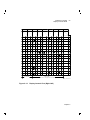
.
.
.
.
.
.
.
.
.
.
.
.
.
.
.
.
.
.
.
.
.
.
.
.
.
.
.
.
.
.
.
.
.
.
.
.
.
.
.
.
.
.
.
.
.
.
.
.
.
.
.
.
.
.
.
.
.
.
.
.
.
.
.
.
.
.
.
.
.
.
.
.
.
.
.
.
.
.
.
.
.
.
.
.
.
330
330
331
331
332
332
334
334
334
335
335
336
xiv Contents
C
Related Documentation
D
Compatibility with Other Digital Terminals
Glossary
Figures
1–1
2–1
2–2
2–3
2–4
2–5
2–6
VT420 Video Display Terminal with Keyboards . . . . . . . . . .
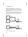
VT Mode Operation . . . . . . . . . . . . . . . . . . . . . . . . . . . . . . .
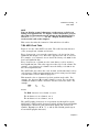
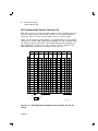
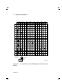
7-Bit ASCII Code Table . . . . . . . . . . . . . . . . . . . . . . . . . . . .
7-Bit Code . . . . . . . . . . . . . . . . . . . . . . . . . . . . . . . . . . . . . .
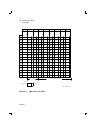
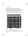
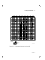
8-Bit Code Table . . . . . . . . . . . . . . . . . . . . . . . . . . . . . . . . .
8-Bit Code . . . . . . . . . . . . . . . . . . . . . . . . . . . . . . . . . . . . . .
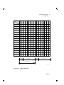
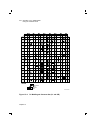
DEC Multinational Character Set (Left Half—C0 and GL
Codes) . . . . . . . . . . . . . . . . . . . . . . . . . . . . . . . . . . . . . . . . .
2–7 DEC Multinational Character Set (Right Half—C1 and GR
Codes) . . . . . . . . . . . . . . . . . . . . . . . . . . . . . . . . . . . . . . . . .
2–8 ISO Latin Nr 1 Supplemental Character Set . . . . . . . . . . . .
2–9 DEC Special Graphic Character Set . . . . . . . . . . . . . . . . . . .
2–10 DEC Technical Character Set . . . . . . . . . . . . . . . . . . . . . . . .
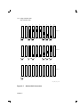
2–11 Display Controls Font (Left Half) . . . . . . . . . . . . . . . . . . . . .
2–12 Display Controls Font (Right Half) . . . . . . . . . . . . . . . . . . .
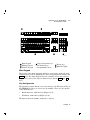
3–1 ANSI Keyboard . . . . . . . . . . . . . . . . . . . . . . . . . . . . . . . . . .
3–2 Short ANSI Keyboard . . . . . . . . . . . . . . . . . . . . . . . . . . . . .
3–3 PC Keyboard (North American/United Kingdom Keyboard) .
3–4 Standard Key with a Data Processing Character
(French/Belgian ANSI Keyboard) . . . . . . . . . . . . . . . . . . . . .
5–1 Character Set Selection . . . . . . . . . . . . . . . . . . . . . . . . . . . .
5–2 Designating and Mapping Character Sets in VT400 Mode . .
5–3 Designating and Mapping Character Sets in VT100 Mode . .
5–4 Character Cell Sizes for 24-Line by 80- and 132-Column
Fonts . . . . . . . . . . . . . . . . . . . . . . . . . . . . . . . . . . . . . . . . . .
5–5 Character Body Sizes for 24-Line by 80- and 132-Column
Fonts . . . . . . . . . . . . . . . . . . . . . . . . . . . . . . . . . . . . . . . . . .
5–6 Example of an Uppercase D (24-Line by 80-Column Font) . .
5–7 Sixel-to-ASCII Conversion . . . . . . . . . . . . . . . . . . . . . . . . . .
.
.
.
.
.
.
5
14
18
19
21
22
.
24
.
.
.
.
.
.
.
.
.
25
26
29
30
52
53
58
59
60
.
.
.
.
62
92
96
97
.
103
.
.
.
105
108
112
Contents xv
6–1
6–2
6–3
10–1
14–1
14–2
15–1
15–2
15–3
15–4
15–5
15–6
A Page in Page Memory . . . . . . . . . . . . . . . . . . . . . . . . . . .
Page Sizes for One Session . . . . . . . . . . . . . . . . . . . . . . . .
Page Sizes for Two Sessions . . . . . . . . . . . . . . . . . . . . . . . .
The Difference Between Scrolling and Panning . . . . . . . . .
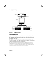
Typical MSC Environments . . . . . . . . . . . . . . . . . . . . . . . .
Typical SSU Environment . . . . . . . . . . . . . . . . . . . . . . . . .
PC TERM Mode Operation . . . . . . . . . . . . . . . . . . . . . . . .
PC International and PC Multilingual Character Sets (CO
and GL) . . . . . . . . . . . . . . . . . . . . . . . . . . . . . . . . . . . . . . .
PC International Character Set (C1 and GR) . . . . . . . . . . .
PC Multilingual Character Set (C1 and GR) . . . . . . . . . . .
North American PC Keyboard (101 Keys) . . . . . . . . . . . . .
Worldwide PC Keyboard (102 Keys) . . . . . . . . . . . . . . . . . .
.
.
.
.
.
.
.
.
.
.
.
.
.
.
127
128
129
175
298
299
308
.
.
.
.
.
.
.
.
.
.
314
315
316
320
321
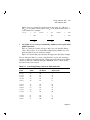
National Replacement Character Sets . . . . . . . . . . . . . . . . . .
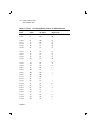
C0 (7-Bit) Control Characters Recognized . . . . . . . . . . . . . . .
C1 (8-Bit) Control Characters Recognized . . . . . . . . . . . . . . .
8-Bit Control Characters and Their 7-Bit Equivalents . . . . . .
Displaying Controls in 36 or 48 Lines . . . . . . . . . . . . . . . . . .
Codes Sent by Editing Keys (ANSI/Short ANSI Keyboards) .
Codes Sent by Editing Keys (PC Keyboard) . . . . . . . . . . . . . .
Codes Sent by Arrow Keys . . . . . . . . . . . . . . . . . . . . . . . . . . .
Codes Sent by Numeric Keypad Keys (ANSI, Short ANSI,
and PC Keyboards) . . . . . . . . . . . . . . . . . . . . . . . . . . . . . . . .
Codes Sent by Numeric Keypad Keys (PC Keyboard, PC Key
Layout) . . . . . . . . . . . . . . . . . . . . . . . . . . . . . . . . . . . . . . . . .
Codes Sent by the Top-Row Function Keys . . . . . . . . . . . . . .
Keys Used to Send 7-Bit Control Characters . . . . . . . . . . . . .
Control Functions Ignored in Level 1 (VT100 mode) . . . . . . .
Character Sets Available . . . . . . . . . . . . . . . . . . . . . . . . . . . .
Designating a Character Set . . . . . . . . . . . . . . . . . . . . . . . . .
Character Set Codes . . . . . . . . . . . . . . . . . . . . . . . . . . . . . . .
Mapping Character Sets with Locking Shifts . . . . . . . . . . . . .
Character Cell Sizes . . . . . . . . . . . . . . . . . . . . . . . . . . . . . . . .
Guidelines for Designing Soft Characters . . . . . . . . . . . . . . .
28
31
33
35
49
65
65
66
Tables
2–1
2–2
2–3
2–4
2–5
3–1
3–2
3–3
3–4
3–5
3–6
3–7
4–1
5–1
5–2
5–3
5–4
5–5
5–6
67
71
73
78
84
90
93
94
98
104
106
xvi Contents
5–7
5–8
5–9
6–1
6–2
7–1
7–2
8–1
9–1
10–1
11–1
11–2
11–3
11–4
11–5
11–6
12–1
12–2
12–3
12–4
12–5
13–1
13–2
15–1
15–2
15–3
15–4
15–5
15–6
15–7
A–1
Converting Binary Code to an ASCII Character . . . . . . . . .
DECDLD Parameter Characters . . . . . . . . . . . . . . . . . . . . .
Valid DECDLD Parameter Combinations . . . . . . . . . . . . . .
Page Format Sequences . . . . . . . . . . . . . . . . . . . . . . . . . . . .
Sequences for Moving Through Page Memory . . . . . . . . . . .
Visual Character Attribute Values . . . . . . . . . . . . . . . . . . . .
Visual Character and Line Attribute Sequences . . . . . . . . .
Editing Sequences . . . . . . . . . . . . . . . . . . . . . . . . . . . . . . . .
Rectangular Area Control Functions . . . . . . . . . . . . . . . . . .
Cursor Movement and Panning Sequences . . . . . . . . . . . . .
ANSI and Short ANSI Keyboards . . . . . . . . . . . . . . . . . . . .
PC Keyboards . . . . . . . . . . . . . . . . . . . . . . . . . . . . . . . . . . .
Keyboard Control Sequences . . . . . . . . . . . . . . . . . . . . . . . .
Programming UDKs . . . . . . . . . . . . . . . . . . . . . . . . . . . . . . .
Printing Control Sequences . . . . . . . . . . . . . . . . . . . . . . . . .
Screen Display Control Sequences . . . . . . . . . . . . . . . . . . . .
Alias Primary DA Responses From the VT420 . . . . . . . . . . .
ANSI Modes for DECRQM, DECRPM, SM, and RM . . . . . .
DEC Private Modes for DECRQM, DECRPM, SM, and RM .
Control Functions for DECRQSS Requests . . . . . . . . . . . . .
Sequences for VT420 Reports . . . . . . . . . . . . . . . . . . . . . . . .
Soft Terminal Reset (DECSTR) States . . . . . . . . . . . . . . . . .
VT420 Reset Sequences . . . . . . . . . . . . . . . . . . . . . . . . . . . .
Control Codes for PC Character Sets . . . . . . . . . . . . . . . . . .
PC Keyboard Commands in PC TERM Mode . . . . . . . . . . . .
National PC Character Sets . . . . . . . . . . . . . . . . . . . . . . . . .
Scan Codes Sent by Standard Keys . . . . . . . . . . . . . . . . . . .
Scan Codes Sent by Editing and Arrow Keys . . . . . . . . . . . .
Scan Codes Sent by Numeric Keypad Keys . . . . . . . . . . . . .
Scan Codes Sent by Programmable Function Keys . . . . . . .
VT52 Escape Sequences . . . . . . . . . . . . . . . . . . . . . . . . . . . .
.
.
.
.
.
.
.
.
.
.
.
.
.
.
.
.
.
.
.
.
.
.
.
.
.
.
.
.
.
.
.
109
116
121
140
141
143
147
158
172
185
207
208
222
225
226
227
231
259
260
266
274
285
293
310
312
317
322
324
325
326
328
About This Manual
This reference manual is for people with a general knowledge of computer
programming. The manual provides programmers with information
needed in writing applications for the VT420 text terminal.
For general user information, see Installing and Using the VT420 Video
Terminal.
New Features in This Revision
This revised manual provides new information on operating a VT420 text
terminal in PC TERM mode.
There are several versions of the VT420 text terminal:
•
North American model—Operates in VT mode.
•
Worldwide model—Operates in VT mode.
•
Worldwide model with PC TERM mode—Operates in VT mode or PC
TERM mode.
xvii
xviii About This Manual
Organization
The manual is divided into five parts.
Part 1: Introduction to Your VT420 Terminal
Part 1 covers information you need to know before you begin programming
the terminal.
•
Chapter 1, ‘‘VT420 Features,’’ provides an overview of the terminal.
The chapter briefly describes the terminal’s major features and
operating modes.
•
Chapter 2, ‘‘Character Encoding,’’ describes the character-encoding
concepts used by the VT420. The chapter also describes the terminal’s
character sets, the format for control functions, and commands for
using macros.
Part 2: Control Functions Sent to the Host
Part 2 covers the codes sent from the keyboard.
•
Chapter 3, ‘‘ANSI, Short ANSI, and PC Keyboard Codes,’’ describes
the characters and control functions that the terminal sends to the
host.
Part 3: Control Functions Received from the Host
Part 3 covers the control functions you can use to program the terminal
in VT mode or PC TERM mode. Part 5 describes features unique to PC
TERM mode.
•
Chapter 4, ‘‘Emulating VT Series Terminals,’’ describes the control
functions used to emulate Digital’s other VT series terminals.
•
Chapter 5, ‘‘Using Character Sets,’’ describes the control functions
used to select the terminal’s built-in character sets and your own soft
character sets.
•
Chapter 6, ‘‘Page Memory,’’ describes the control functions used to
format and move through the terminal’s page memory.
•
Chapter 7, ‘‘Setting Visual Character and Line Attributes,’’ describes
the control functions used to highlight text, such as bolding and
underlining.
•
Chapter 8, ‘‘Editing,’’ describes the control functions used to edit
characters in the terminal’s page memory.
About This Manual
xix
•
Chapter 9, ‘‘Rectangular Area Operations,’’ describes the control
functions used to manipulate rectangular areas of text.
•
Chapter 10, ‘‘Cursor Movement and Panning,’’ describes the control
functions used to move the cursor and pan through data in page
memory.
•
Chapter 11, ‘‘Keyboard, Printing, and Display Commands,’’ describes
the control functions used to program the terminal’s keyboard, printer
port, and display screen.
•
Chapter 12, ‘‘VT420 Reports,’’ describes the control functions used to
request reports on the operating state of the terminal. The chapter
also describes the format of the reports sent by the terminal, and the
control functions use to restore the terminal to a previous state.
•
Chapter 13, ‘‘Resetting and Testing the Terminal,’’ describes the
control functions used to reset and test the terminal’s operating
features.
Part 4: Dual Sessions
Part 4 describes two methods for managing sessions on the VT420—
multiple system communications (MSC) and SSU software.
•
Chapter 14, ‘‘Session Management,’’ describes MSC and SSU. The
chapter also lists shared and independent resources available to each
session when you use two sessions.
Part 5: Emulating a Personal Computer
Part 5 describes how the VT420 model with PC TERM mode can emulate
a personal computer (PC).
•
Chapter 15, ‘‘Operating in PC TERM Mode,’’ describes how the
terminal operates in PC TERM mode. The chapter describes control
characters, PC character sets, and codes the PC keyboard sends to the
host.
Appendices
•
Appendix A, ‘‘VT52 Mode Control Codes,’’ describes control functions
used when the terminal is in VT52 mode.
•
Appendix B, ‘‘Communication,’’ describes how the terminal
communicates with the host system and local devices, such as modems
and printers. The appendix also provides cabling information and
describes how to connect to non-Digital systems.
xx About This Manual
•
Appendix C, ‘‘Related Documentation,’’ lists other VT420
documentation you can order from Digital.
•
Appendix D, ‘‘Compatibility with Other Digital Terminals,’’ compares
the VT420 video terminal to Digital’s VT320 and VT220 video
terminals.
Conventions
The following conventions are used in this manual:
Notes
Provide general operating information.
Programming tips
Provide helpful suggestions to consider when writing
applications.
Set-up features
The names of features appear in bold type.
Example: Use the save feature in the Set-Up
Directory screen.
Set-up feature settings and fields appear in this
type.
Example: The cursor is on the Global field in the
Set-Up Directory.
ANSI keyboard keys
Appear as normal text in a box .
Example: Press the Return key.
PC keyboard keys
Appear as bold text in a box .
Example: Press the Enter key.
ANSI keys (with PC
keys)
When a PC command sequence differs from an ANSI
command sequence, the PC key sequence appears in
parentheses after the ANSI sequence.
Example: Press the Return key ( Enter ).
Ctrl key
For Ctrl key sequences, hold down Ctrl and press the
other key.
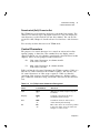
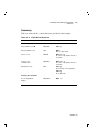
Characters in control
functions
Appear in bold type. Variables appear in italics.
Below each character is a column/row number that
indicates the character’s position in a standard code
table.
Example:
ESC
1/11
#
2/3
6
3/6
Control function
Column/row
numbers
About This Manual
Glossary entries
xxi
Appear in italics when first used in text.
Example: The VT420 stores information in its page
memory.
Part 1
Introduction to Your
VT420 Terminal
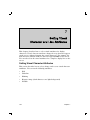
1
1
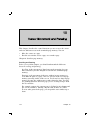
VT420 Features
This chapter provides an overview of the VT420 video terminal. The
chapter briefly describes the major features and operating modes of the
terminal.
VT420 Models
The VT420 is a monochrome text terminal. The terminal has two major
components, a monitor/terminal unit and a keyboard. The monitor has a
tilt-swivel base.
The VT420 is available in three models: worldwide, worldwide with PC
TERM mode, and North American.
•
The worldwide model supports 8-bit multinational character sets
and several 7-bit national replacement character sets (NRCs) for
western Europe. This model has two system communication ports
(6-pin, DEC-423 port and 25-pin, RS-232 port) and a detachable power
cord.
•
The worldwide model with PC TERM mode provides all the
features of the worldwide model, plus an operating mode that supports
personal computer (PC) character sets and PC application software.
•
The North American model is similiar to the worldwide model,
but does not support the NRC sets or PC TERM mode. This model
has one system communication port (6-pin, DEC-423 port) and an
attached power cord.
Chapter 1
3
4 VT420 Features
VT420 Models
All models have a 6-pin, DEC-423 printer port. The printer port can also
serve as an extra communication port for connection to a host computer.
Users can select whether this port acts as a local printer port or an extra
communication port, by setting a feature in the Global Set-Up screen.
This manual covers the programming information you need to use the
features for the terminal. The terminal uses control functions specified by
the American National Standards Institute (ANSI) and the International
Organization for Standardization (ISO).
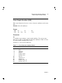
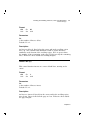
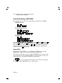
Keyboards
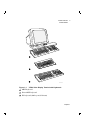
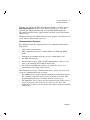
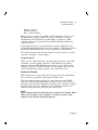
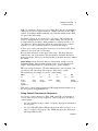
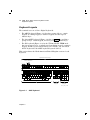
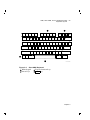
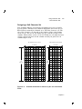
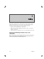
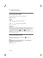
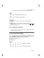
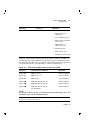
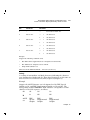
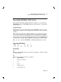
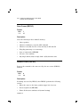
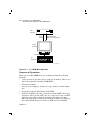
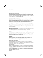
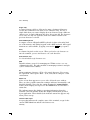
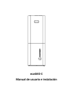
The terminal uses one of three Digital keyboards (Figure 1–1):
•
ANSI keyboard
•
Short ANSI keyboard
•
PC keyboard (with 101 or 102 keys)
The ANSI and PC keyboards are available in various models for different
languages. The PC keyboard is for the VT worldwide model with PC
TERM mode; the North American model has 101 keys, and other models
have 102 keys. You can use the ANSI and short ANSI keyboards with any
VT420 model. See Installing and Using the VT420 Video Terminal with
PC Terminal Mode for a comparison of the three keyboards.
The next section describes some of the important new features of the
terminal.
Chapter 1
VT420 Features
VT420 Models
5
1
2
KEYBOARD 102
3
LJ-01105-TI0
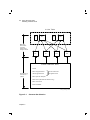
Figure 1–1
VT420 Video Display Terminal with Keyboards
1
ANSI keyboard
2
Short ANSI keyboard
3
PC keyboard (102-key model shown)
Chapter 1
6 VT420 Features
New Features
New Features
The VT420 is compatible with Digital’s VT320 terminal and offers major
new features, such as the ability to use PC applications, two sessions, and
two windows. You can also create macros and perform rectangular area
editing. Local page memory provides faster on-line transaction processing.
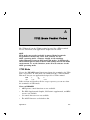
PC TERM Mode
The VT420 worldwide model with PC TERM mode supports PC character
sets and PC application software. Chapter 15 describes PC TERM mode
and PC character sets.
Two Sessions
When you electronically connect to a host system from your terminal, you
start an interactive session. The VT420 lets you run two sessions at the
same time. That is, you can connect to two different jobs on your system.
If you connect your VT420 to two systems, you can log in to both systems
and run those sessions at the same time. If you are using a PC keyboard,
you can select a different operating mode for each session — VT mode
or PC TERM mode. If you connect your VT420 to a terminal server that
supports several systems, you can run two VT mode sessions, each on a
different system.
The two-sessions feature gives you two terminals in one. The VT420
maintains the two sessions separately. You can easily switch back and
forth between the two sessions from the keyboard.
The VT420 has two different methods for managing dual sessions,
multiple system communications (MSC) and Digital’s SSU protocol.
•
MSC
Uses two separate communication lines to maintain two sessions at
the same time.
•
SSU (VT mode only)
Uses one communication line and Digital’s proprietary SSU software
protocol to maintain two sessions at the same time. The SSU protocol
is available as a separate VMS layered software product or as part of
a DECServer 200, DECserver 300, or DECserver 500 system.
You can select different operating features for each session. For example,
you can use different set-up selections, page memory format, and userdefined keys.
For more information on session management, see Chapter 14.
Chapter 1
VT420 Features
New Features
7
User Windows
The VT420 lets you view data from two sessions at the same time. To
view data from two sessions, you divide the screen into two windows.
By default, each session you open with a VT420 terminal uses the
complete screen. This means the terminal can only display data from
one session at a time. To divide the screen into two windows, you press a
sequence of keys. Each window is assigned to a session. Information from
one session appears in one half of the screen, information from the second
session appears in the other half.
You can divide the screen horizontally. When you divide the screen, a
border appears across the middle of the screen from column 1 to the last
column.
For more information on user windows, see Installing and Using the
VT420 Video Terminal.
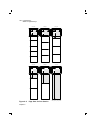
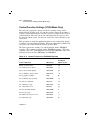
Page Memory
In VT mode, the VT420 has a multiple-page display memory. The
multiple-page feature lets the terminal store more text than appears
on the screen. For example, when you use two sessions the terminal
can store up to three screen areas of text (three 24-line pages) for each
session.
In PC TERM mode, the host system stores data.
Page memory provides a storage space for pop-up menus and a means
for instant screen updates. You can select different page sizes. The page
sizes available depend on whether you are running one or two sessions.
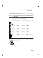
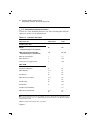
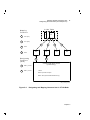
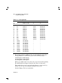
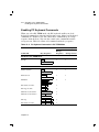
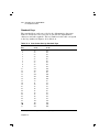
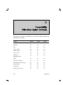
Two Sessions
•
3 pages of 24 lines
•
2 page of 25 lines
•
2 pages of 36 lines
•
1 page of 48 lines
80 or 132 columns
•
1 page of 72 lines
80 or 132 columns
80 or 132 columns
80 or 132 columns
80 or 132 columns
One Session
•
6 pages of 24 lines
80 or 132 columns
•
5 pages of 25 lines
80 or 132 columns
•
4 pages of 36 lines
80 or 132 columns
Chapter 1
8 VT420 Features
New Features
•
3 pages of 48 lines
80 or 132 columns
•
2 pages of 72 lines
80 or 132 columns
•
1 page of 144 lines
80 or 132 columns
A page is a section of the terminal’s page memory. Each page has left,
right, top and bottom margins. You can define the size and layout of a
page by using set-up features or control functions.
For more information on page memory, see Chapter 6.
Macro Feature
This feature lets you download ANSI text and commands into the
terminal. The terminal stores the text and commands until you invoke
them with a control function. The macro feature provides you with more
convenience and flexibility. It lets you execute a group of ANSI control
functions as a set. For more information, see Chapter 2.
Rectangular Area Operations
This feature lets you manipulate rectangular areas of text within page
memory. You can
•
Copy them from one area in page memory to another.
•
Erase them.
•
Fill them with a character of your choice.
•
Change or reverse their visual character attributes.
For more information, see Chapter 9.
Local Copy and Paste Feature (VT Mode)
This feature lets you copy text from the screen to an internal buffer. You
can later send the text to the host. This feature is useful for copying text
from the terminal screen to the host application.
Number of Lines/Screen
The VT420 has three different character font heights, so users can
display 24, 36, or 48 lines of text on the screen. For more information,
see Chapter 11.
Chapter 1
VT420 Features
General Features
9
General Features
This section describes the general operating and communication features
of the terminal. You can set many of these features from the keyboard,
using set-up.
Set-Up
Set-up is a series of display screens. Each screen lists a group of features,
such as communications or printing.
You can use set-up screens to examine and change the current settings for
features. For example, you can select the keyclick feature, transmit and
receive speeds, page size, and type of session management.
The VT420 set-up feature is similar to the VT320 set-up feature.
Installing and Using the VT420 Video Terminal describes the set-up
screens in detail.
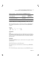
Display Features
The VT420 screen has the following basic features:
•
359 mm (14-inch), flat-screen monitor
•
24, 36, or 48 display lines at a time
800 (horizontal)
•
400 (vertical) pixels
A separate status line for each session, at the bottom of the screen
(You can disable the status line to have an additional line for data
display.)
•
Horizontal split-screen scrolling on any line boundary
(same as the VT100)
Text Features
The VT420 provides a variety of text and editing features.
•
Character sets
– 5 sets of 94 characters each
– 1 set of 96 characters
– National replacement character sets (worldwide model)
– 3 PC sets of 128 characters each (worldwide model with PC TERM
mode)
– Downloadable character set (94 or 96 characters)
Chapter 1
10 VT420 Features
General Features
•
•
ANSI keyboard function keys
– 5 local function keys
– 15 user-definable keys
PC keyboard function keys
– 3 local function keys
– 30 user-definable keys (VT mode)
51 user-definable keys (PC TERM mode)
PC keyboard scan codes sent to the host
•
All VT320 editing functions
•
Normal, bold, underline, blinking, and reverse video characters
•
Single-width/single-height lines
Double-width/single-height lines
Double-width/double-height lines
•
Control characters and functions
– 7-bit and 8-bit control characters
– ANSI control functions
– DEC private control functions
– Ability to display control functions
•
Character Sets
The VT420 has the following built-in character sets:
•
•
•
•
•
•
•
ASCII
DEC Supplemental Graphic
ISO Latin Alphabet Nr 1 supplemental graphic
National replacement character sets (NRCs)
(worldwide model)
DEC Technical
DEC Special Graphic (VT100 line drawing)
PC character sets (worldwide model with PC TERM mode)
— PC International
— PC Multilingual
— PC Danish/Norwegian
— PC Portuguese
— PC Spanish
You can also design a soft character set, then load it from the host system
into the terminal.
Chapter 1
VT420 Features
General Features
11
Together, the ASCII and DEC Supplemental Graphic sets make up the
DEC Multinational character set. When you turn on or reset the
terminal, the VT420 automatically uses the DEC Multinational set.
The ASCII and ISO Latin-1 supplemental sets make up the ISO Latin-1
character set.
Chapter 2 describes the VT420 character sets. Chapter 5 describes how to
select and use different character sets.
Communication Features
The VT420 provides the following features for communicating with the
host system:
•
7-bit or 8-bit environments
•
XPC communication protocol, which defines the XON and XOFF
points
•
Asynchronous communication speeds up to 38,400 bits/second
•
One DEC-423 host port
•
One RS-232 host port, with a 25-pin D-subminiature connector for a
host or external modem (worldwide model only)
•
One bidirectional DEC-423 printer port, which also serves as a
communication port with a host system
The VT420 has two major communication states, on-line and local. You
select the communication state in set-up.
•
The on-line state lets the terminal communicate with a host system.
The terminal sends data entered at the keyboard to the host. The
terminal displays data received from the host on the screen.
•
The local state lets you place the host system on hold. Data entered
at the keyboard is sent to the screen, but not to the host. The
terminal stores data received from the host, until you put the terminal
back on-line.
Chapter 1
12 VT420 Features
Operating Modes
Operating Modes
The VT420 has four major operating modes for text operations. The
VT420 with PC TERM mode has five major operating modes. You can
select each mode from the keyboard (using set-up screens), or from the
host (using control codes). The VT420 uses standard ANSI functions in
all operating modes, except VT52 mode and PC TERM mode.
VT400 mode, 7-bit controls
VT100 mode
VT400 mode, 8-bit controls
VT52 mode
PC TERM mode
VT400 mode, 7-bit controls is the default operating mode. This mode
provides the full range of VT420 capabilities, using 8-bit characters and
7-bit control characters. All character sets are available. This mode
provides full compatibility with Digital’s VT300 series terminals. Digital
recommends this mode for most applications.
VT400 mode, 8-bit controls provides the full range of VT420
capabilities, using 8-bit characters and 8-bit control characters. All VT
mode character sets are available, and the terminal recognizes both 7-bit
and 8-bit controls.
In this mode, the terminal can run VT300 applications that use 8-bit
control characters. The worldwide model with PC TERM mode can use
a PC keyboard. The terminal operates most efficiently in this mode, but
some systems and applications do not yet support 8-bit operation.
PC TERM mode enables the terminal to support PC application software
and character sets. The terminal sends scan codes to the host, which PC
applications recognize. The terminal sends scan codes when you press a
key and when you release a key. This mode requires a PC keyboard.
VT100 mode provides full compatibility with Digital’s VT102 terminal.
This mode restricts the terminal to a 7-bit environment. The keyboard is
restricted to VT100 keys, and the only available character sets are ASCII,
national replacement characters, and DEC Special Graphic. You can use
this mode with applications that require strict VT100 compatibility.
VT52 mode provides full compatibility with Digital’s VT52 terminal.
This mode only uses Digital’s private control functions, not standard
ANSI functions. You use this mode with applications written for the
VT52.
Chapter 2 describes the format for 7-bit and 8-bit character codes.
Chapter 4 describes how the VT420 can emulate other VT series
terminals.
Chapter 1
22
Character Encoding
This chapter describes the character-encoding system that the terminal
uses in VT mode to communicate with a host system. See Chapter 15 for
a description of PC TERM mode. You must have a basic understanding
of the character-encoding system described in this chapter before you use
the control functions in the rest of this manual.
The chapter also describes the character sets available in VT mode and
the format for sending control functions to the terminal. You can select
character sets for different countries or for special uses, such as technical
characters. You use control functions to make the terminal perform
special functions, such as editing or printing.
Overview
The VT420 uses a communication line to exchange information with a
host system. The terminal and the host send data in an encoded form
that is different from what you see on the screen.
In VT mode, the keys you type on your keyboard send scan codes to the
terminal. The terminal converts the scan codes to character codes or
ANSI control functions, then sends the information to the host. The host
stores the information and passes it to application software programs. For
example, your host may have applications that let you do word processing,
data entry, or programming.
The host processes the output from the application software and displays
it on the terminal’s screen. You can print the data by sending it to a
printer connected to the terminal.
Chapter 2
13
14 Character Encoding
Overview
Host
Computer
ASCII Characters
ANSI Control Sequences
VT420
Terminal
VT Mode
(VT400, VT300, VT200, VT100, VT52)
ANSI
Keyboard
Short ANSI
Keyboard
(VT400, VT300, VT200, VT100)
PC
Keyboard
LJ-01476-TI0
Figure 2–1
VT Mode Operation
Coding Standards
All terminals and computers encode information as binary digits, or bits.
Older systems use 7 bits to encode each character. Newer systems such as
the VT420 use 8 bits, which provide more codes. The newer systems can
also use the 7-bit codes.
The VT420 uses an 8-bit character-encoding system and a 7-bit code
extension technique. The ‘‘7-Bit Code Extension Technique’’ section in this
chapter explains what 7-bit code extensions are.
The American National Standards Institute (ANSI) and International
Organization for Standardization (ISO) specify standards for character
encoding in the information-processing industry. The VT420 terminal is
compatible with the following ANSI and ISO standards.
Chapter 2
Character Encoding
Coding Standards
15
Standard
Description
dpANS X3.134.1
8-Bit ASCII structure and rules
dpANS X3.134.2
Code for information interchange of 7-bit and
8-bit ASCII supplemental multilingual graphic
character set
ANSI X3.4—1977
American Standard Code for Information
Interchange (ASCII)
ANSI X3.41—1974
Code Extension Techniques for Use with the 7-Bit
Coded Character Set of American National Code
Information Interchange
ANSI X3.32—1973
Graphic Representation of the Control Characters
of American National Code for Information
Interchange
ANSI X3.64—1979
Additional Controls for Use with American
National Standard for Information Interchange
ISO 646—1977
7-Bit Coded Character Set for Information
Processing Interchange
ISO 2022
7-Bit and 8-Bit Coded Character Sets—Code
Extension Techniques
ISO 6429
Additional Control Functions for Character
Imaging Devices
ISO 8859-1
8-Bit single byte code graphic character sets-Part
1: Latin Alphabet Nr 1
ISBN 2-12-953907-0
ISO international register of character sets used
with escape sequences
You can order ANSI and ISO standards from the following sources:
ANSI Standards
Sales Department
American National Standards Institute
1430 Broadway
New York, NY 10018
ISO Standards
CCITT
UN Book Store
United Nations Building
New York, NY 10017
Chapter 2
16 Character Encoding
Characters and Character Sets
Characters and Character Sets
In Digital’s computing environment, a character is a symbol represented
by an 8-bit binary code. These symbols include letters, digits, and
punctuation marks, as well as other symbols used to organize, control,
or represent data.
Here are a few examples of characters and their corresponding 8-bit codes.
Character
Code
A
01000001
}
01111101
CSI
10011011
There are two types of computing environments, 7-bit and 8-bit. In a
7-bit environment, only the last 7 bits of the character code define the
character. In an 8-bit environment, all 8 bits define the character.
The A character above is defined in a 7-bit or 8-bit environment, because
the eighth bit of the code is 0. The 8-bit form of the CSI character is
defined only in a 8-bit environment, because its eighth bit is 1.
A coded character set is a group of characters that conform to certain
rules and standards. These standards are set by organizations such ANSI
and ISO. Each character in a character set is represented by a different
combination of 8 bits.
Code Table
A code table is a convenient way to show all the characters in a character
set with their codes. Most standard character sets put similar characters
into groups, so they have similar codes. A code table lets you see groups
of characters and their relative codes clearly.
There are two basic types of characters, graphic characters and control
characters. These two character types are defined by ANSI and ISO
standards. The VT420 processes received characters based on these two
character types.
Graphic characters are characters you can display. Graphic characters
include letters, numbers, punctuation marks, and any other characters
you can display.
Control characters are characters you do not usually display. They
make the terminal or host system perform specific functions in data
communications and text processing.
Chapter 2
Character Encoding
Code Table
17
NOTE
You can display control characters on the screen, to help you
debug your applications. To display control characters, you set
the control representation mode feature in the Display Set-Up
screen to Display Controls. See the ‘‘Display Controls Mode’’
section at the end of this chapter.
This section describes the format for 7-bit and 8-bit code tables.
7-Bit ASCII Code Table
Figure 2–2 is the 7-bit ASCII code table. The table has 128 character
codes, arranged in 8 columns and 16 rows.
Every character in a row uses the same binary code for its four least
significant bits (Figure 2–3). This value appears at the left of each row.
For example, every character in row 0 uses the binary code 0000 for its
four least significant bits.
Every character in a column uses the same binary code for its three
most significant bits. This value appears at the top of each column. For
example, every character in column 0 uses the binary code 000 for its
three most significant bits.
The ASCII table also shows the octal, decimal, and hexadecimal code for
each character. Different programmers may prefer using octal, decimal,
or hexadecimal codes for different purposes.
This manual refers to characters by their position in the table. For
example, the character H is at 4/8 (column 4, row 8). You can use the
column/row number to find a character and its codes in the table. For
example
ESC
1/11
#
2/3
6
3/6
means
The ESC character is at column 1, row 11.
The # character is at column 2, row 3.
The 6 character is at column 3, row 6.
The ASCII graphic characters are in positions 2/1 through 7/14 of the
ASCII table. ASCII graphic characters include all American and English
alphanumeric characters, plus punctuation marks and various text
symbols. Examples are C, n, ", !, +, and $. (The British pound sign is
not an ASCII graphic character.)
Chapter 2
18 Character Encoding
Code Table
0
Column
Bits
b8
b5
3
0
0
0
6
0
1
1
1
1
5
0
0
0
0
4
0
0
0
b6
0
2
0
0
b7
Row
1
0
1
0
1
7
0
0
1
0
1
1
1
0
1
0
1
100
64
40
101
65
41
102
66
42
103
67
43
104
68
44
105
69
45
106
70
46
107
71
47
110
72
48
111
73
49
112
74
4A
113
75
4B
114
76
4C
115
77
4D
116
78
4E
117
79
4F
120
80
50
121
81
51
122
82
52
123
83
53
124
84
54
125
85
55
126
86
56
127
87
57
130
88
58
131
89
59
132
90
5A
133
91
5B
134
92
5C
135
93
5D
136
94
5E
137
95
5F
140
96
60
141
97
61
142
98
62
143
99
63
144
100
64
145
101
65
146
102
66
147
103
67
150
104
68
151
105
69
152
106
6A
153
107
6B
154
108
6C
155
109
6D
156
110
6E
157
111
6F
160
112
70
161
113
71
162
114
72
163
115
73
164
116
74
165
117
75
166
118
76
167
119
77
170
120
78
171
121
79
172
122
7A
173
123
7B
174
124
7C
175
125
7D
176
126
7E
177
127
7F
b4 b3 b2 b1
0
0
0
0
NUL
1
0
0
0
1
SOH
2
0
0
1
0
STX
3
0
0
1
1
ETX
4
0
1
0
0
EOT
5
0
1
0
1
ENQ
6
0
1
1
0
ACK
7
0
1
1
1
BEL
8
1
0
0
0
BS
9
1
0
0
1
HT
10
1
0
1
0
LF
11
1
0
1
1
VT
12
1
1
0
0
FF
13
1
1
0
1
CR
14
1
1
1
0
SO
15
1
1
1
1
SI
0
0
0
1
1
1
2
2
2
3
3
3
4
4
4
5
5
5
6
6
6
7
7
7
10
8
8
11
9
9
12
10
A
13
11
B
14
12
C
15
13
D
16
14
E
17
15
F
DLE
DC1
(XON)
DC2
DC3
(XOFF)
DC4
NAK
SYN
ETB
CAN
EM
SUB
ESC
FS
GS
RS
US
20
16
10
21
17
11
22
18
12
23
19
13
24
20
14
25
21
15
26
22
16
27
23
17
30
24
18
31
25
19
32
26
1A
33
27
1B
34
28
1C
35
29
1D
36
30
1E
37
31
1F
SP
!
"
#
$
%
&
’
(
)
*
+
,
.
/
40
32
20
41
33
21
42
34
22
43
35
23
44
36
24
45
37
25
46
38
26
47
39
27
50
40
28
51
41
29
52
42
2A
53
43
2B
54
44
2C
55
45
2D
56
46
2E
57
47
2F
0
1
2
3
4
5
6
7
8
9
:
;
<
=
>
C0 Codes
?
60
48
30
61
49
31
62
50
32
63
51
33
64
52
34
65
53
35
66
54
36
67
55
37
70
56
38
71
57
39
72
58
3A
73
59
3B
74
60
3C
75
61
3D
76
62
3E
77
63
3F
@
A
B
C
D
E
F
G
H
I
J
K
L
M
N
O
P
Q
R
S
T
U
V
W
X
Y
Z
[
\
]
^
_
‘
a
b
c
d
e
f
g
h
i
j
k
l
m
n
o
p
q
r
s
t
u
v
w
x
y
z
{
|
}
~
DEL
GL Codes (ASCII Graphic)
Key
Character
ESC
33
27
1B
Octal
Decimal
Hex
GSF_0586_89.DG
Figure 2–2
Chapter 2
7-Bit ASCII Code Table
Character Encoding
Code Table
Bit
7
Bit
6
Bi t
5
Bi t
4
Bi t
3
Bi t
2
19
Bi t
1
3 M ost
S i g n i f i c an t Bi ts
4 L e a st
Si g n i fi ca n t Bi ts
(D e c i m a l Va l u e i s
Column in
Code Table)
( D e ci m a l Va l u e i s
Row in
C o d e Ta b l e )
GSF_0583_89.DG
Figure 2–3
7-Bit Code
The ASCII control characters are in positions 0/0 through 1/15 (columns
0 and 1) of the ASCII table. The SP character (2/0) may act as a graphic
space character or a control character, depending on the context. DEL
(7/15) is always a control character.
ANSI and ISO standards define control character codes and their
functions. These standards also define the mnemonic used to represent
each control character in a code table. Here are some examples of ASCII
control characters with their mnemonics.
ASCII Control Character
Mnemonic
(Appears in Code Table)
Carriage return
CR
Form feed
FF
Cancel
CAN
Chapter 2
20 Character Encoding
Code Table
8-Bit Code Table
Figure 2–4 shows the format for an 8-bit code table. It has the same
number of rows as the 7-bit table, but twice as many columns and
character code positions.
Each character in a row of the 8-bit table uses the same binary code for
its four least significant bits (Figure 2–5). Each character in a column
uses the same binary code for its four most significant bits.
The codes on the left half of the 8-bit table (columns 0 through 7) work
like the codes in the 7-bit table. You can use these codes in a 7-bit or 8-bit
environment. The eighth bit of these codes is 0.
The codes on the right half of the table (columns 8 through 15) have an
eighth bit of 1. You can only use these codes in an 8-bit environment.
The 8-bit code table has two sets of control characters, C0 (control zero)
and C1 (control one). The VT420 uses the ANSI definitions for the
functions of C0 and C1 controls. The C0 controls are in columns 0 and 1.
The C0 controls are the same as the ASCII control characters in the 7-bit
table. You can use C0 controls in a 7-bit environment.
The C1 controls are in columns 8 and 9. They perform different functions
than the C0 controls. You can only use C1 controls directly in an 8-bit
environment. You can select C1 codes indirectly in a 7-bit environment.
The ‘‘7-Bit Code Extension Technique’’ section in this chapter explains
how to select C1 controls indirectly. Some C1 code positions are blank,
because their functions are not yet standardized.
Chapter 2
Character Encoding
Code Table
21
Col umn
00
01
02
00
NUL
DLE
SP
01
SOH
DC1
PU1
02
STX
DC2
PU2
03
ETX
DC3
STS
04
EOT
DC4
IND
CCH
05
ENQ NAK
NEL
MW
06
ACK
SYN
SSA
SPA
07
BEL
ETB
ESA
EPA
08
BS
CAN
HTS
09
HT
EM
HTJ
10
LF
SUB
VTS
11
VT
ESC
PLD
CSI
12
FF
FS
PLU
ST
13
CR
GS
RI
OSC
14
SO
RS
SS2
PM
15
SI
US
SS3
APC
Row
C0 Codes
03
04
05
06
07
08
09
10
11
12
13
14
15
DCS
DEL
GL Codes
C1 Codes
GR Codes
7- Bi t Co d e Ta b l e
GSF_0584_89.DG
Figure 2–4
8-Bit Code Table
Chapter 2
22 Character Encoding
Code Table
Bit
8
Bit
7
Bi t
6
Bi t
5
Bi t
4
Bi t
3
Bi t
2
Bi t
1
4 M o st
S i g n i f i c a n t Bi ts
4 L e a st
Si g n i fi ca n t Bi ts
(D e c i m a l Va l u e i s
Column in
Code Table)
( D e ci m a l Va l u e i s
Row in
C o d e Ta b l e )
GSF_0585_89.DG
Figure 2–5
8-Bit Code
NOTE
The VT420 does not recognize all C0 and C1 codes. Tables 2–2 and
2–3 list the codes the terminal recognizes. The terminal generally
ignores all other control codes.
The table also has two sets of graphic characters, GL (graphic left) and
GR (graphic right). There are 94 GL codes in positions 2/1 through 7/14.
You can use GL codes in 7-bit or 8-bit environments.
There are 96 GR codes in positions 10/0 through 15/15. Some 8-bit
character sets only use 94 of these GR codes. You can use GR codes
only in an 8-bit environment.
Together, the GL and GR sets make up the terminal’s in-use table. The
in-use table contains the graphic characters the terminal can currently
use. Before the terminal can display and send characters from a character
set, the set must be mapped into the in-use table. Chapter 5 describes the
in-use table in detail.
Chapter 2
Character Encoding
VT420 Character Sets
23
VT420 Character Sets
The VT420 provides the following built-in graphic character sets:
ASCII
DEC Supplemental Graphic
ISO Latin Alphabet Nr 1 supplemental graphic
National replacement character sets (NRCs)
DEC Special Graphic
DEC Technical
See Chapter 15 for additional sets available in PC TERM mode. You can
also design and load a soft character set into the terminal.
Downloadable (soft) set
All VT420 character sets contain graphic and control characters. The
function of control characters never change, no matter what character
set you use. The terminal always interprets C0 and C1 control codes as
defined by ANSI.
The terminal stores the codes for graphic characters in GL and GR
tables. Selecting a new character set changes the characters associated
with the GL or GR codes. When you turn on or reset the terminal, you
automatically select the following character sets:
ASCII in GL
DEC Supplemental (or ISO Latin-1 supplemental) graphic in GR
Together, the ASCII set and one of the supplemental sets make up a
multinational character set.
•
The ASCII set and DEC Supplemental Graphic sets are known as the
DEC Multinational character set.
•
The ASCII set and the ISO Latin-1 supplemental set are known as
the ISO Latin Alphabet Nr 1 set.
You select the supplemental set with (1) the UPSS (user-preferred
supplemental set) feature in the General Set-Up screen, or (2) the
assign user-preferred supplemental set (DECAUPSS) control function
(Chapter 5).
Chapter 2
24 Character Encoding
VT420 Character Sets
DEC Supplemental Graphic Character Set
This 8-bit character set has 94 graphic characters. The graphic characters
include accented letters and diacritical marks, used in many European
languages. There are also special symbols, such as currency signs.
When you first turn on your terminal, you automatically select the ASCII
character set and the DEC Supplemental Graphic set. The terminal maps
the ASCII set into its GL table, and the DEC Supplemental Graphic set
into its GR table. Together, these two character sets are known as the
DEC Multinational character set (Figures 2–6 and 2–7).
0
Column
Bits
b8
2
0
0
4
0
0
0
1
5
0
0
1
0
b5
3
0
0
0
b6
Row
1
0
b7
1
0
6
0
1
0
1
7
0
1
0
1
0
1
1
1
0
1
0
1
100
64
40
101
65
41
102
66
42
103
67
43
104
68
44
105
69
45
106
70
46
107
71
47
110
72
48
111
73
49
112
74
4A
113
75
4B
114
76
4C
115
77
4D
116
78
4E
117
79
4F
120
80
50
121
81
51
122
82
52
123
83
53
124
84
54
125
85
55
126
86
56
127
87
57
130
88
58
131
89
59
132
90
5A
133
91
5B
134
92
5C
135
93
5D
136
94
5E
137
95
5F
140
96
60
141
97
61
142
98
62
143
99
63
144
100
64
145
101
65
146
102
66
147
103
67
150
104
68
151
105
69
152
106
6A
153
107
6B
154
108
6C
155
109
6D
156
110
6E
157
111
6F
160
112
70
161
113
71
162
114
72
163
115
73
164
116
74
165
117
75
166
118
76
167
119
77
170
120
78
171
121
79
172
122
7A
173
123
7B
174
124
7C
175
125
7D
176
126
7E
177
127
7F
b4 b3 b2 b1
0
0
0
0
0
NUL
1
0
0
0
1
SOH
2
0
0
1
0
STX
3
0
0
1
1
ETX
4
0
1
0
0
EOT
5
0
1
0
1
ENQ
6
0
1
1
0
ACK
7
0
1
1
1
BEL
8
1
0
0
0
BS
9
1
0
0
1
HT
10
1
0
1
0
LF
11
1
0
1
1
VT
12
1
1
0
0
FF
13
1
1
0
1
CR
14
1
1
1
0
SO
15
1
1
1
1
SI
0
0
0
1
1
1
2
2
2
3
3
3
4
4
4
5
5
5
6
6
6
7
7
7
10
8
8
11
9
9
12
10
A
13
11
B
14
12
C
15
13
D
16
14
E
17
15
F
DLE
DC1
(XON)
DC2
DC3
(XOFF)
DC4
NAK
SYN
ETB
CAN
EM
SUB
ESC
FS
GS
RS
US
20
16
10
21
17
11
22
18
12
23
19
13
24
20
14
25
21
15
26
22
16
27
23
17
30
24
18
31
25
19
32
26
1A
33
27
1B
34
28
1C
35
29
1D
36
30
1E
37
31
1F
C0 Codes
SP
!
"
#
$
%
&
’
(
)
*
+
,
.
/
40
32
20
41
33
21
42
34
22
43
35
23
44
36
24
45
37
25
46
38
26
47
39
27
50
40
28
51
41
29
52
42
2A
53
43
2B
54
44
2C
55
45
2D
56
46
2E
57
47
2F
0
1
2
3
4
5
6
7
8
9
:
;
<
=
>
?
60
48
30
61
49
31
62
50
32
63
51
33
64
52
34
65
53
35
66
54
36
67
55
37
70
56
38
71
57
39
72
58
3A
73
59
3B
74
60
3C
75
61
3D
76
62
3E
77
63
3F
@
A
B
C
D
E
F
G
H
I
J
K
L
M
N
O
P
Q
R
S
T
U
V
W
X
Y
Z
[
\
]
^
_
‘
a
b
c
d
e
f
g
h
i
j
k
l
m
n
o
p
q
r
s
t
u
v
w
x
y
z
{
|
}
~
DEL
GL Codes (ASCII Graphic)
Key
Character
ESC
33
27
1B
Octal
Decimal
Hex
GSF_0586_89.DG
Figure 2–6
Codes)
Chapter 2
DEC Multinational Character Set (Left Half—C0 and GL
Character Encoding
VT420 Character Sets
25
NOTE
All control function descriptions in this manual assume that the
terminal is using the DEC Multinational set.
The DEC Supplemental Graphic set is the right half of the DEC
Multinational set (Figure 2–7). The C1 controls are in columns 8 and
9. The graphic characters are in columns 10 through 15.
You can select the DEC Supplemental Graphic set as the default by using
control functions (Chapter 5) or the UPSS feature in the General Set-Up
screen. You can use the DEC Supplemental Graphic set in VT400 mode
and PC TERM mode.
8
9
1
10
1
0
11
1
0
0
0
0
0
12
1
0
1
1
13
1
1
1
0
14
1
1
0
1
15
1
1
0
0
Column
Bits
b8
1
b7
1
1
b6
1
1
0
b5
1
b4 b3 b2 b1 Row
HTJ
VTS
PLD
PLU
RI
SS2
SS3
STS
CCH
MW
SPA
EPA
CSI
ST
OSC
PM
APC
C1 Codes
Y
S
o
c
a
_
<<
240
160
A0
241
161
A1
242
162
A2
243
163
A3
244
164
A4
245
165
A5
246
166
A6
247
167
A7
250
168
A8
251
169
A9
252
170
AA
253
171
AB
254
172
AC
255
173
AD
256
174
AE
257
175
AF
+
_
2
3
lu
.
1
o
_
>>
1/4
1 /2
?
HTS
PU2
c||
S
ESA
PU1
I
SSA
DCS
220
144
90
221
145
91
222
146
92
223
147
93
224
148
94
225
149
95
226
150
96
227
151
97
230
152
98
231
153
99
232
154
9A
233
155
9B
234
156
9C
235
157
9D
236
158
9E
237
159
9F
I
IND
NEL
200
128
80
201
129
81
202
130
82
203
131
83
204
132
84
205
133
85
206
134
86
207
135
87
210
136
88
211
137
89
212
138
8A
213
139
8B
214
140
8C
215
141
8D
216
142
8E
217
143
8F
260
176
B0
261
177
B1
262
178
B2
263
179
B3
264
180
B4
265
181
B5
266
182
B6
267
183
B7
270
184
B8
271
185
B9
272
186
BA
273
187
BB
274
188
BC
275
189
BD
276
190
BE
2727
191
BF
A
A
^
A
A
..
A
A
E
E
^
E
..
E
I
I
^I
..
I
300
192
C0
301
193
C1
302
194
C2
303
195
C3
304
196
C4
305
197
C5
306
198
C6
307
199
C7
310
200
C8
311
201
C9
312
202
CA
313
203
CB
314
204
CC
315
205
CD
316
206
CE
317
207
CF
N
O
O
^
O
O
..
O
O
U
U
^
U
..
U
..
Y
320
208
D0
321
209
D1
322
210
D2
323
211
D3
324
212
D4
325
213
D5
326
214
D6
327
215
D7
330
216
D8
331
217
D9
332
218
DA
333
219
DB
334
220
DC
335
221
DD
336
222
DE
337
223
DF
a
a
^
a
a
..
a
a
e
e
^
e
..
e
I
I
^I
..
I
340
224
E0
341
225
E1
342
226
E2
343
227
E3
344
228
E4
345
229
E5
346
230
E6
347
231
E7
350
232
E8
351
233
E9
352
234
EA
353
235
EB
354
236
EC
355
237
ED
356
238
EE
357
239
EF
n
o
o
^
o
o
..
o
o
u
u
^
u
..
u
..
y
360
240
F0
361
241
F1
362
242
F2
363
243
F3
364
244
F4
365
245
F5
366
246
F6
367
247
F7
370
248
F8
371
249
F9
372
250
FA
373
251
FB
374
252
FC
375
253
FD
376
254
FE
377
255
FF
0
0
0
1
1
1
0
2
0
1
1
3
0
1
0
0
4
0
1
0
1
5
0
1
1
0
6
0
1
1
1
7
1
0
0
0
8
1
0
0
1
9
1
0
1
0
10
1
0
1
1
11
1
1
0
0
12
1
1
0
1
13
0
0
0
0
0
0
0
0
1
1
1
0
14
1
1
1
1
15
G R C o d e s ( D E C S u p p l e m e n t a l G ra p h i c )
GSF_0587_89.DG
Figure 2–7
Codes)
DEC Multinational Character Set (Right Half—C1 and GR
Chapter 2
26 Character Encoding
VT420 Character Sets
ISO Latin Alphabet Nr 1 Supplemental Character Set
This 8-bit character set has 96 graphic characters. The graphic characters
are similar to those in the DEC Supplemental Graphic set. The ISO
Latin-1 supplemental set includes accented letters and diacritical marks,
used in many European languages. It also has other special symbols and
letters, not included in the DEC Supplemental Graphic set.
Figure 2–8 shows the ISO Latin-1 supplemental set. The C1 controls are
in columns 8 and 9. The graphic characters are in columns 10 through
15.
8
9
1
10
1
0
11
1
0
0
0
0
0
12
1
0
1
0
14
1
1
1
1
13
1
1
0
1
15
1
1
0
0
Column
b8
1
Bits
b7
1
1
1
b6
1
0
b5
1
b4 b3 b2 b1
HTS
HTJ
VTS
PLD
PLU
RI
SS2
SS3
STS
CCH
MW
SPA
EPA
CSI
ST
OSC
PM
APC
C1 Codes
c||
o
Y
I
I
S
"
c
a
_
<<
R
240
160
A0
241
161
A1
242
162
A2
243
163
A3
244
164
A4
245
165
A5
246
166
A6
247
167
A7
250
168
A8
251
169
A9
252
170
AA
253
171
AB
254
172
AC
255
173
AD
256
174
AE
257
175
AF
+
_
2
3
lu
.
1
o
_
>>
1/4
1 /2
3 /4
?
ESA
PU2
NBSP
S
SSA
PU1
220
144
90
221
145
91
222
146
92
223
147
93
224
148
94
225
149
95
226
150
96
227
151
97
230
152
98
231
153
99
232
154
9A
233
155
9B
234
156
9C
235
157
9D
236
158
9E
237
159
9F
I
NEL
DCS
I
IND
200
128
80
201
129
81
202
130
82
203
131
83
204
132
84
205
133
85
206
134
86
207
135
87
210
136
88
211
137
89
212
138
8A
213
139
8B
214
140
8C
215
141
8D
216
142
8E
217
143
8F
260
176
B0
261
177
B1
262
178
B2
263
179
B3
264
180
B4
265
181
B5
266
182
B6
267
183
B7
270
184
B8
271
185
B9
272
186
BA
273
187
BB
274
188
BC
275
189
BD
276
190
BE
2727
191
BF
A
A
^
A
A
..
A
A
E
E
^
E
..
E
I
I
^I
..
I
300
192
C0
301
193
C1
302
194
C2
303
195
C3
304
196
C4
305
197
C5
306
198
C6
307
199
C7
310
200
C8
311
201
C9
312
202
CA
313
203
CB
314
204
CC
315
205
CD
316
206
CE
317
207
CF
N
O
O
^
O
O
..
O
O
U
U
^
U
..
U
Y
320
208
D0
321
209
D1
322
210
D2
323
211
D3
324
212
D4
325
213
D5
326
214
D6
327
215
D7
330
216
D8
331
217
D9
332
218
DA
333
219
DB
334
220
DC
335
221
DD
336
222
DE
337
223
DF
a
a
^
a
a
..
a
a
e
e
^
e
..
e
I
I
^I
..
I
340
224
E0
341
225
E1
342
226
E2
343
227
E3
344
228
E4
345
229
E5
346
230
E6
347
231
E7
350
232
E8
351
233
E9
352
234
EA
353
235
EB
354
236
EC
355
237
ED
356
238
EE
357
239
EF
n
o
o
^
o
o
..
o
.
.
o
u
u
^
u
..
u
y
..
y
360
240
F0
361
241
F1
362
242
F2
363
243
F3
364
244
F4
365
245
F5
366
246
F6
367
247
F7
370
248
F8
371
249
F9
372
250
FA
373
251
FB
374
252
FC
375
253
FD
376
254
FE
377
255
FF
Row
0
0
0
0
0
0
0
0
1
1
0
0
1
0
2
0
0
1
1
3
0
1
0
0
4
0
1
0
1
5
0
1
1
0
6
0
1
1
1
7
1
0
0
0
8
1
0
0
1
9
1
0
1
0
10
1
0
1
1
11
1
1
0
0
12
1
1
0
1
13
1
1
1
0
14
1
1
1
1
15
GR Codes
(I S O L a t i n - 1 S u p p l e m e n t a l G ra p h i c )
GSF_0592_89.DG
Figure 2–8
ISO Latin Nr 1 Supplemental Character Set
You can select the ISO Latin-1 supplemental set as the default by using
control functions (Chapter 5) or the UPSS feature in the General Set-Up
Chapter 2
Character Encoding
VT420 Character Sets
27
screen. The combination of the ASCII character set in GL and the ISO
Latin-1 supplemental set in GR is called the ISO Latin Alphabet Nr 1
character set.
You can use the ISO Latin-1 set in VT400 mode and PC TERM mode.
National Replacement Character Sets (NRC Sets)
(Worldwide Models Only)
The NRC sets provide character sets for many European languages.
There are several NRC sets. Each is a 7-bit character set with 94 graphic
characters. The NRC sets are similar to the ASCII set, except for a few
characters. See Chapter 15 for additional 8-bit sets available in PC TERM
mode.
NOTE
Digital recommends that you operate the terminal in an 8-bit
environment. The NRC sets are only provided for compatibility
with 7-bit environments.
Table 2–1 lists the characters in each NRC set that are different from
the ASCII set. To use an NRC set, you must select national replacement
character set mode. You can select this mode by using a control function
(Chapter 4) or the character set mode feature in the General Set-Up
screen. You can only use one NRC set at a time. The NRC set used
depends on the keyboard selected in set-up, as follows:
Keyboard
United Kingdom
Danish
Finnish
Flemish
French/Belgian
French Canadian
Canadian English
German
Italian
Norwegian
Portuguese
Spanish
Swedish
Swiss (French)
Swiss (German)
NRC Set
United Kingdom
Norwegian/Danish
Finnish
French
French
French Canadian
French Canadian
German
Italian
Norwegian/Danish
Portuguese
Spanish
Swedish
Swiss
Swiss
Chapter 2
28 Character Encoding
VT420 Character Sets
Table 2–1 National Replacement Character Sets
Character Set
2/3
4/0
5/11
5/12
5/13
5/14
ASCII
United Kingdom
Finnish
French
French Canadian
German
Italian
Norwegian/Danish
Portuguese
Spanish
Swedish
Swiss
#
£
#
£
#
#
£
#
#
£
#
ù
@
@
@
à
à
§
§
@
@
§
É
à
[
[
Ä
°
â
Ä
°
Æ
Ã
¡
Ä
é
\
\
Ö
ç
ç
Ö
ç
Ø
Ç
Ñ
Ö
ç
]
]
Å
§
ê
Ü
é
Å
Õ
¿
Å
ê
^
^
Ü
^
î
^
^
^
^
^
Ü
î
Character Set
5/15
6/0
7/11
7/12
7/13
7/14
ASCII
United Kingdom
Finnish
French
French Canadian
German
Italian
Norwegian/Danish
Portuguese
Spanish
Swedish
Swiss
_
_
_
_
_
_
_
_
_
_
_
è
`
`
é
`
ô
`
ù
`
`
`
é
ô
{
{
ä
é
é
ä
à
æ
ã
°
ä
ä
|
|
ö
ù
ù
ö
ò
ø
ç
ñ
ö
ö
}
}
å
è
è
ü
è
å
õ
ç
å
ü
~
~
ü
Chapter 2
û
ß
ì
~
~
~
ü
û
Character Encoding
VT420 Character Sets
29
DEC Special Graphic Character Set
This 7-bit character set has 94 graphic characters. Most of the graphic
characters are also in the ASCII character set. The other graphic
characters include special symbols and line-drawing characters.
Figure 2–9 shows the DEC Special Graphic set. The C0 controls are in
columns 0 and 1. The graphic characters are in columns 2 through 7.
Another name for this character set is the VT100 line-drawing character
set. The line-drawing characters let you create a limited range of pictures
when you use the VT420 as a text terminal.
You can use the DEC Special Graphic set to replace the ASCII set in GL
or the DEC Supplemental Graphic set in GR. Chapter 5 describes how to
select character sets.
0
Column
1
2
3
4
5
6
7
Bits
0
b7
Row
0
0
0
b6
b5
b4 b3 b2 b1
0
0
0
0
0
1
0
0
0
1
SOH
2
0
0
1
0
STX
3
0
0
1
1
ETX
4
0
1
0
0
EOT
5
0
1
0
1
ENQ
6
0
1
1
0
ACK
7
0
1
1
1
BEL
8
1
0
0
0
BS
9
1
0
0
1
HT
10
1
0
1
0
LF
11
1
0
1
1
VT
12
1
1
0
0
FF
13
1
1
0
1
CR
14
1
1
1
0
SO
15
1
1
1
1
SI
NUL
0
0
1
1
0
1
0
0
0
1
1
1
2
2
2
3
3
3
4
4
4
5
5
5
6
6
6
7
7
7
10
8
8
11
9
9
12
10
A
13
11
B
14
12
C
15
13
D
16
14
E
17
15
F
20
16
10
21
17
11
22
18
12
23
19
13
24
20
14
25
21
15
26
22
16
27
23
17
30
24
18
31
25
19
32
26
1A
33
27
1B
34
28
1C
35
29
1D
36
30
1E
37
31
1F
40
32
20
41
33
21
42
34
22
43
35
23
44
36
24
45
37
25
46
38
26
47
39
27
50
40
28
51
41
29
52
42
2A
53
43
2B
54
44
2C
55
45
2D
56
46
2E
57
47
2F
60
48
30
61
49
31
62
50
32
63
51
33
64
52
34
65
53
35
66
54
36
67
55
37
70
56
38
71
57
39
72
58
3A
73
59
3B
74
60
3C
75
61
3D
76
62
3E
77
63
3F
DC1
(XON)
DC2
DC3
(XOFF)
DC4
NAK
SYN
ETB
CAN
EM
SUB
ESC
FS
GS
RS
US
C0 Codes
SP
!
"
#
$
%
&
’
(
)
*
+
,
.
/
0
1
2
3
4
5
6
7
8
9
:
;
<
=
>
?
1
0
1
DLE
1
1
0
0
0
@
A
B
C
D
E
F
G
H
I
J
K
L
M
N
O
1
1
1
100
64
40
101
65
41
102
66
42
103
67
43
104
68
44
105
69
45
106
70
46
107
71
47
110
72
48
111
73
49
112
74
4A
113
75
4B
114
76
4C
115
77
4D
116
78
4E
117
79 (BLANK)
4F
P
Q
R
S
T
U
V
W
X
Y
Z
[
\
]
^
1
0
120
80
50
121
81
51
122
H
82
T
52
123
F
83
F
53
124
84
54
125
L
85
F
55
126
86
56
127
87
57
130
N
88
L
58
131
Y
89
T
59
132
90
5A
133
91
5B
134
92
5C
135
93
5D
136
94
5E
137
95
5F SCAN 1
+
_
140
96
60
141
97
61
142
98
62
143
99
63
144
100
64
145
101
65
146
102
66
147
103
67
150
104
68
151
105
69
152
106
6A
153
107
6B
154
108
6C
155
109
6D
156
110
6E
157
111
6F
1
SCAN 3
SCAN 5
SCAN 7
SCAN 9
<
_
>
_
=/
.
DEL
160
112
70
161
113
71
162
114
72
163
115
73
164
116
74
165
117
75
166
118
76
167
119
77
170
120
78
171
121
79
172
122
7A
173
123
7B
174
124
7C
175
125
7D
176
126
7E
177
127
7F
GL Codes (DEC Special Graphic)
Key
Character
ESC
33
27
1B
Octal
Decimal
Hex
GSF_0589_89.DG
Figure 2–9
DEC Special Graphic Character Set
Chapter 2
30 Character Encoding
VT420 Character Sets
DEC Technical Character Set
This 7-bit character set has 94 graphic characters. The DEC Technical set
has characters and symbols often used in technical applications, such as
schematic and logic diagrams.
Figure 2–10 shows the DEC Technical character set. The C0 controls are
in columns 0 and 1. The graphic characters and symbols are in columns 2
through 7. You can use the characters in positions 2/1 through 3/7 to form
large composite characters.
You can use the DEC Technical set to replace the ASCII set in GL or
the DEC Supplemental Graphic set in GR. You can only use the DEC
Technical set in VT400 mode.
0
0
0
1
0
Bits
0
0
0
3 11
41
33
21
42
34
22
43
35
23
44
36
24
45
37
25
46
38
26
47
39
27
50
40
28
51
41
29
52
42
2A
53
43
2B
54
44
2C
55
45
2D
56
46
2E
57
47
2F
60 260
48 176
30
B0
61 261
49 177
31
B1
62 262
50 178
32
B2
63 263
51 179
33
B3
64 264
52 180
34
B4
65 265
53 181
35
B5
66 266
54 182
36
B6
67 267
55 183
37
B7
70 270
56 184
38
B8
71 271
57 185
39
B9
72 272
58 186
3A
BA
73 273
59 187
3B
BB
74 274
60 188
3C BC
75 275
61 189
3D BD
76 276
62 190
3E
BE
77 2727
63 191
3F
BF
0
0
0
1
1
0
0
1
0
2
0
0
1
1
0
1
0
0
0
1
0
1
5
0
1
1
0
6
7
3
4
0
1
1
1
1
0
0
0
1
0
0
1
9
8
1
0
1
0
10
1
0
1
1
11
1
1
0
0
12
1
1
0
1
13
1
1
1
0
14
1
1
1
1
15
Key
Character
241
161
A1
242
162
A2
243
163
A3
244
164
A4
245
165
A5
246
166
A6
247
167
A7
250
168
A8
251
169
A9
252
170
AA
253
171
AB
254
172
AC
255
173
AD
256
174
AE
257
175
AF
?
GL GR
∆
Φ
Γ
Θ
Λ
300
192
C0
301
193
C1
302
194
C2
303
195
C3
304
196
C4
305
197
C5
306
198
C6
307
199
C7
310
200
C8
311
201
C9
312
202
CA
313
203
CB
314
204
CC
315
205
CD
316
206
CE
317
207
CF
Ψ
Σ
Ω
Ξ
Τ
U
120
80
50
121
81
51
122
82
52
123
83
53
124
84
54
125
85
55
126
86
56
127
87
57
130
88
58
131
89
59
132
90
5A
133
91
5B
134
92
5C
135
93
5D
136
94
5E
137
95
5F
320
208
D0
321
209
D1
322
210
D2
323
211
D3
324
212
D4
325
213
D5
326
214
D6
327
215
D7
330
216
D8
331
217
D9
332
218
DA
333
219
DB
334
220
DC
335
221
DD
336
222
DE
337
223
DF
1
GL GR
5 13
Π
1
0
GL GR
4 12
100
64
40
101
65
41
102
66
42
103
67
43
104
68
44
105
69
45
106
70
46
107
71
47
110
72
48
111
73
49
112
74
4A
113
75
4B
114
76
4C
115
77
4D
116
78
4E
117
79
4F
1
1
1
U
2 10
Column
0
0
1
0
0
GL GR
Row
0
0
1
0
1
GL GR
b4 b3 b2 b1
0
1
1
b5
U
0
b6
U
0
b7
∆
b8
GL GR
6 14
α
β
χ
δ
ε
φ
γ
η
ι
θ
κ
λ
ν
140
96
60
141
97
61
142
98
62
143
99
63
144
100
64
145
101
65
146
102
66
147
103
67
150
104
68
151
105
69
152
106
6A
153
107
6B
154
108
6C
155
109
6D
156
110
6E
157
111
6F
340
224
E0
341
225
E1
342
226
E2
343
227
E3
344
228
E4
345
229
E5
346
230
E6
347
231
E7
350
232
E8
351
233
E9
352
234
EA
353
235
EB
354
236
EC
355
237
ED
356
238
EE
357
239
EF
7 15
π
ψ
ρ
σ
τ
f
?
ω
ξ
υ
ζ
160
112
70
161
113
71
162
114
72
163
115
73
164
116
74
165
117
75
166
118
76
167
119
77
170
120
78
171
121
79
172
122
7A
173
123
7B
174
124
7C
175
125
7D
176
126
7E
360
240
F0
361
241
F1
362
242
F2
363
243
F3
364
244
F4
365
245
F5
366
246
F6
367
247
F7
370
248
F8
371
249
F9
372
250
FA
373
251
FB
374
252
FC
375
253
FD
376
254
FE
Codes
101 301
65 193
C1
41
Octal
Decimal
Hex
* Note
When Set is Mapped Into GR
Bit B8 is 1
GSF_0590_89.DG
Figure 2–10
Chapter 2
DEC Technical Character Set
Character Encoding
VT420 Character Sets
31
Downloaded (Soft) Character Set
The VT420 lets you download a character set from the host system. The
character set can have up to 96 graphic characters. You can design your
own character set, then load the set into the terminal. You can use the
set in GL or GR. Chapter 5 describes how to load and use a soft character
set.
You can only use this character set in VT400 mode.
Control Characters
The purpose of a control character is to control an action such as line
spacing, paging, or data flow. The terminal does not display control
characters unless you select display controls mode (described later in this
chapter). There are two groups of control characters.
C0
7-bit control characters, in columns 0 and 1
of the 8-bit code table
C1
8-bit control characters, in columns 8 and 9
of the 8-bit code table
Table 2–2 lists the C0 control characters the VT420 recognizes. Table 2–3
lists the C1 control characters the VT420 recognizes. You can also code
C1 control characters as 7-bit escape sequences. Table 2–4 lists the
equivalent 7-bit sequences for 8-bit control characters. All three tables
give column/row locations to help you find the characters in the character
sets.
Table 2–2 C0 (7-Bit) Control Characters Recognized
Mnemonic
Column/Row
Function
Null
NUL
0/0
NUL has no function (ignored by the
terminal).
Enquiry
ENQ
0/5
Sends the answerback message.
(Communications Set-Up)
Bell
BEL
0/7
Sounds the bell tone if the bell is
enabled in Keyboard Set-Up.
BS
BS
0/8
Moves the cursor one character position
to the left. If the cursor is at the left
margin, no action occurs.
Name
Chapter 2
32 Character Encoding
Control Characters
Table 2–2 (Cont.) C0 (7-Bit) Control Characters Recognized
Name
Mnemonic
Column/Row
Function
Horizontal tab
HT
0/9
Moves the cursor to the next tab stop.
If there are no more tab stops, the
cursor moves to the right margin. HT
does not cause text to auto wrap.
Line feed
LF
0/10
Causes a line feed or a new line
operation, depending on the setting
of line feed/new line mode.
Vertical tab
VT
0/11
Treated as LF.
Form feed
FF
0/12
Treated as LF.
Carriage return
CR
0/13
Moves the cursor to the left margin on
the current line.
Shift out
(locking
shift 1)
SO (LS1)
0/14
Maps the G1 character set into
GL. You designate G1 by using a
select character set (SCS) sequence
(Chapter 5).
Shift in (locking
shift 0)
SI (LS0)
0/15
Maps the G0 character set into
GL. You designate G0 by using a
select character set (SCS) sequence
(Chapter 5).
Device control 1
(XON)
DC1
1/1
Also known as XON. If XON/XOFF flow
control is enabled in Communications
Set-Up, DC1 clears DC3 (XOFF). This
action causes the VT420 to continue
sending characters.
Device control 3
(XOFF)
DC3
1/3
Also known as XOFF. If XON
/XOFF flow control is enabled in
Communications Set-Up, DC3 causes
the VT420 to stop sending characters.
The terminal cannot resume sending
characters until it receives a DC1
control character.
Chapter 2
Character Encoding
Control Characters
33
Table 2–2 (Cont.) C0 (7-Bit) Control Characters Recognized
Name
Mnemonic
Column/Row
Function
Device control 4
DC4
1/4
Introduces an SSU session
management command. The VT420
and host use this control to separate
SSU commands from ANSI text and
control functions. See Chapter 14.
Cancel
CAN
1/8
Immediately cancels an escape
sequence, control sequence, or device
control string in progress. The VT420
does not display any error characters.
Substitute
SUB
1/10
Immediately cancels an escape
sequence, control sequence, or device
control string in progress. The VT420
displays a reverse question mark for an
error character.
Escape
ESC
1/11
Introduces an escape sequence. ESC
also cancels any escape sequence,
control sequence, or device control
string in progress.
Delete
DEL
7/15
Ignored when received, unless a 96character set is mapped into GL. DEL
is not used as a fill character. Digital
does not recommend using DEL as a fill
character. Use NUL instead.
Table 2–3 C1 (8-Bit) Control Characters Recognized
Name
Mnemonic
Column/Row
Function
Index
IND
8/4
Moves the cursor down one line in the
same column. If the cursor is at the
bottom margin, the page scrolls up.
Next line
NEL
8/5
Moves the cursor to the first position
on the next line. If the cursor is at the
bottom margin, the page scrolls up.
Chapter 2
34 Character Encoding
Control Characters
Table 2–3 (Cont.) C1 (8-Bit) Control Characters Recognized
Name
Mnemonic
Column/Row
Function
Horizontal
tab set
HTS
8/8
Sets a horizontal tab stop at the column
where the cursor is.
Reverse index
RI
8/13
Moves the cursor up one line in the same
column. If the cursor is at the top margin,
the page scrolls down.
Single shift 2
SS2
8/14
Temporarily maps the G2 character set
into GL, for the next graphic character.
You designate the G2 set by using a select
character set (SCS) sequence (Chapter 5).
Single shift 3
SS3
8/15
Temporarily maps the G3 character set
into GL, for the next graphic character.
You designate the G3 set by using a select
character set (SCS) sequence (Chapter 5).
Device control
string
DCS
9/0
Introduces a device control string.
Used for loading function keys or a soft
character set.
Start of string
SOS
9/8
Ignored.
DEC
private
identification
DECID
9/10
Makes the terminal send its device
attributes response to the host (same
as an ANSI device attributes (DA)
sequence). Programs should use the
ANSI DA sequence instead.
NOTE
If the printer is in controller mode,
the terminal sends the sequence to
the printer.
Control
sequence
introducer
CSI
9/11
Introduces a control sequence.
String
terminator
ST
9/12
Ends a device control string. You use ST
in combination with DCS.
Chapter 2
Character Encoding
Control Characters
35
Table 2–3 (Cont.) C1 (8-Bit) Control Characters Recognized
Mnemonic
Column/Row
Function
Operating
system
command
OSC
9/13
Introduces an operating system
command.
Privacy
message
PM
9/14
Introduces a privacy message string.
Application
program
command
APC
9/15
Introduces an application program
command.
Name
The VT420 ignores all following characters until it receives a SUB, ST, or any other C1
control character.
Table 2–4 8-Bit Control Characters and Their 7-Bit Equivalents
8-Bit
Character
7-Bit
Sequence
Index
IND
8/4
ESC
1/11
D
4/4
Next line
NEL
8/5
ESC
1/11
E
4/5
Horizontal tab set
HTS
8/8
ESC
1/11
H
4/8
Reverse index
RI
8/13
ESC
1/11
M
4/13
Single shift 2
SS2
8/14
ESC
1/11
N
4/14
Single shift 3
SS3
8/15
ESC
1/11
O
4/15
Device control string
DCS
9/0
ESC
1/11
P
5/0
Start of string
SOS
9/8
ESC
1/11
X
5/8
Name
Chapter 2
36 Character Encoding
Control Characters
Table 2–4 (Cont.) 8-Bit Control Characters and Their 7-Bit Equivalents
8-Bit
Character
7-Bit
Sequence
DEC private identification
DECID
9/10
ESC
1/11
Z
5/10
Control sequence
introducer
CSI
9/11
ESC
1/11
[
5/11
String terminator
ST
9/12
ESC
1/11
\
5/12
Operating system
command
OSC
9/13
ESC
1/11
]
5/13
Privacy message
PM
9/14
ESC
1/11
^
5/14
Application program
APC
9/15
ESC
1/11
_
5/15
Name
Control Functions
You use control functions to make the terminal perform special actions in
your applications. These functions range from the simple—editing data—
to the complex—reporting on the terminal’s operating state. The rest of
this manual covers the many uses for control functions. Here are some
examples.
Move the cursor.
Delete a line of text.
Select bold or underlined text.
Change character sets.
Make the terminal emulate a VT52 or VT100 terminal.
There are single-character and multiple-character control functions.
The single-character functions are the C0 and C1 control characters. You
can use C0 characters in a 7-bit or 8-bit environment. C1 characters
provide a few more functions than C0 characters, but you can only use C1
characters directly in an 8-bit environment.
Multiple-character functions provide many more functions than the
C0 and C1 characters. Multiple-character functions can use control
characters and graphic characters. There are three basic types of
multiple-character functions.
Chapter 2
Character Encoding
Control Functions
37
Escape sequences
Control sequences
Device control strings
Many sequences are based on ANSI and ISO standards, and are used
throughout the industry. Others are private sequences created by
manufacturers like Digital for specific families of products. ANSI
sequences and private sequences follow ANSI and ISO standards for
control functions.
In this manual, private control functions created by Digital have the
prefix DEC in their mnemonic name. For example, column mode has the
mnemonic DECCOLM. All other control functions are standardized.
The following sections describe the format for escape sequences, control
sequences, and device control strings.
Programming Tip
When you use control functions, remember that the binary codes define
a function—not the graphic characters. This manual uses graphic
characters from the DEC Multinational character set to show control
functions. If you use another character set, the graphic characters for
control functions may change, but the code is always the same.
Sequence Format
This manual shows escape and control sequences in their 8-bit format.
You can also use equivalent 7-bit sequences (Table 2–4).
The 8-bit format uses the C0 and C1 control characters and ASCII
characters from the DEC Multinational character set. The sequences
also show each character’s column/row position in the character set table,
below the character. The column/row code eliminates confusion over
similar-looking characters such as 0 (3/0) and O (4/15).
NOTE
Spaces appear between characters in a sequence for clarity. These
spaces are not part of the sequence. If a space is part of the
sequence, the SP (2/0) character appears.
Chapter 2
38 Character Encoding
Control Functions
Escape Sequences
An escape sequence uses two or more bytes to define a specific control
function. Escape sequences do not include variable parameters, but
may include intermediate characters. Here is the format for an escape
sequence.
ESC
1/11
I
2/0 to 2/15
F
3/0 to 7/14
Escape
character
Intermediate
characters
(zero or more
characters)
Final
character
(one character)
ESC introduces escape sequences. After receiving the ESC control
character, the terminal interprets the next received characters as part
of the sequence.
I represents zero or more intermediate characters that can follow the ESC
character. Intermediate characters come from the 2/0 through 2/15 range
of the code table.
F is the final character. This character indicates the end of the sequence.
The final character comes from the 3/0 through 7/14 range of the code
table. The intermediate and final characters together define a single
control function.
For example, the following escape sequence changes the current line of
text to double-width, single-height characters:
ESC
1/11
#
2/3
6
3/6
Control Sequences
A control sequence uses two or more bytes to define a specific control
function. Control sequences usually include variable parameters. Here is
the format for a control sequence.
CSI
9/11
P...P
3/0 to 3/15
I...I
2/0 to 2/25
F
4/0 to 7/14
Control
sequence
introducer
Parameter
(zero or more
characters)
Intermediate
(zero or more
characters)
Final
(one character)
CSI is the control sequence introducer. You can also use the equivalent
7-bit sequence, ESC (1/11) [ (5/11), as a substitute for CSI. After receiving
CSI, the terminal interprets the next received characters as part of the
sequence.
Chapter 2
Character Encoding
Control Functions
39
P...P are parameter characters received after CSI. These characters are in
the 3/0 to 3/15 range in the code table. Parameter characters modify the
action or interpretation of the sequence. You can use up to 16 parameters
per sequence. You must use the ; (3/11) character to separate parameters.
All parameters are unsigned, positive decimal integers, with the most
significant digit sent first. Any parameter greater than 9999 (decimal) is
set to 9999 (decimal). If you do not specify a value, a 0 value is assumed.
A 0 value or omitted parameter indicates a default value for the sequence.
For most sequences, the default value is 1.
NOTE
All parameters must be positive decimal integers. Do not use
a decimal point in a parameter—the terminal will ignore the
command.
If the first character in a parameter string is the ? (3/15) character, it
indicates that DEC private parameters follow. The terminal interprets
private parameters according to ANSI X3.64 and ISO 6429.
The VT420 processes two types to parameters, numeric and selective.
Numeric Parameters
A numeric parameter indicates a number value such as a margin location.
In this manual, numeric parameters appear as actual values or as Pn,
Pn1, Pn2, and so on.
The following is an example of a control sequence with numeric
parameters:
CSI
9/11
5
3/5
;
3/11
2
0
3/2 3/0
r
7/2
Control
sequence
introducer
First
numeric
parameter
Delimiter
Second
numeric
parameter
Final
character
This sequence sets the top and bottom margins of the current page. The
top margin is at line 5, the bottom is at line 20. The ; (3/11) separates the
two parameters.
Chapter 2
40 Character Encoding
Control Functions
Selective Parameters
A selective parameter selects an action associated with the specific
parameter. In this manual, selective parameters usually appear as Ps,
Ps1, Ps2, and so on.
The following is an example of a control sequence using selective
parameters:
CSI
9/11
1
3/1
;
3/11
4
3/4
m
6/13
Control
sequence
introducer
First
selective
parameter
Delimiter
Second
selective
parameter
Final
character
This control sequence turns on the bold and underline attribute at the
cursor position. The parameters are 1 (indicating the bold attribute) and
4 (indicating the underline attribute). The ; (3/11) delimiter separates the
two parameters.
I...I are zero or more intermediate characters received after CSI. These
characters are in the 2/0 to 2/15 range.
F is the final character from the 4/0 to 7/14 range. The final character
indicates the end of the sequence. The intermediate and final characters
together define a control function. If there are no intermediate characters,
the final character defines the function.
Device Control Strings
Device control strings (DCS), like control sequences, use two or more
bytes to define specific control functions. However, a DCS also includes a
data string. Here is the format for a device control string.
DCS
9/0
P...P
3/0
to
3/15
I...I
2/0
to
3/15
F
4/0
to
3/15
Data string
************
ST
9/12
Device
control
string
introducer
Zero or
more
parameters
Zero or
more
intermediates
Final
String
String
terminator
DCS is the device control string introducer. DCS is the C1 control
character at position 9/0. You can also use the equivalent 7-bit sequence,
ESC (1/11) P (5/0). After receiving DCS, the terminal processes the next
received characters as part of the string function.
Chapter 2
Character Encoding
Control Functions
41
P..P are parameter characters received after DCS. The use of parameter
characters in a device control string is a Digital extension to the ANSI
syntax. According to ANSI standards, any elements included after DCS
are part of the data string.
Parameter characters are in the 3/0 to 3/15 range. They modify the
action or interpretation of the device control string. You can use up
to 16 parameters per string. Each parameter is separated with a ; (3
/11) character. These characters follow the same rules as in a control
sequence. See the ‘‘Control Sequences’’ section in this chapter.
I...I are zero or more intermediate characters received after CSI. These
characters are in the 2/0 to 2/15 range.
F is the final character in the 4/0 to 7/14 range. The final character
indicates the end of the string. The intermediate and final characters
define the string. If there are no intermediates, the final character defines
the string.
Data string follows the final character and usually includes several
definition strings. Each definition string can be several characters in
length. Individual strings are separated by the ; (3/11) delimiter.
ST is the string terminator. ST (9/12) indicates the end of a string. You
can also use the equivalent 7-bit sequence, ESC (1/11) \ (5/12).
The following is an example of a device control string:
DCS
9/0
0
3/0
!
2/1
u
7/5
%
2/5
Device
control
string
introducer
Parameter
Intermediate
Final
Data
string
5
3/5
ST
9/12
String
terminator
This device control string assigns the DEC Supplemental Graphic set as
the user-preferred supplemental set.
Using Control Characters in Sequences
You can use control characters—ESC, CAN, and SUB—to interrupt or
recover from errors in escape sequences, control sequences, and device
control strings.
•
You can send ESC (1/11) to cancel a sequence in progress and begin a
new sequence.
•
You can send CAN (1/8) to indicate the present data is in error or to
cancel a sequence in progress. The VT420 interprets the characters
following CAN as usual.
Chapter 2
42 Character Encoding
Control Functions
•
You can send SUB (1/10) to cancel a sequence in progress. The VT420
interprets the characters following SUB as usual.
The VT420 does not lose data when errors occur in escape or control
sequences and device control strings. The terminal ignores unrecognized
sequences and strings, unless they end a current escape sequence.
7-Bit Code Extension Technique
You can represent all C1 control characters as 7-bit escape sequences. You
can use the C1 characters indirectly, by representing them as 2-character
escape sequences. ANSI calls this technique a 7-bit code extension. The
7-bit code extension provides a way of using C1 characters in applications
written for a 7-bit environment. Here are some examples.
8-Bit
C1 Character
7-Bit Code Extension
Escape Sequence
CSI
9/11
ESC
1/11
[
5/11
SS3
8/15
ESC
1/11
O
4/15
IND
8/4
ESC
1/11
D
4/4
DCS
9/0
ESC
1/11
P
5/0
In general, you can use the 7-bit code extension technique in two ways.
•
You can represent any C1 control character as a 2-character escape
sequence. The second character of the sequence has a code that is
4016 or 6410 less than the code of the C1 character.
•
You can make any escape sequence whose second character is in the
range of 4/0 through 5/15 one byte shorter by removing the ESC
character and adding 4016 to the code of the second character. This
generates an 8-bit control character. For example, you can change
ESC [ to CSI with this method.
Chapter 2
Character Encoding
Working with 7-Bit and 8-Bit Environments
43
Working with 7-Bit and 8-Bit Environments
There are three requirements for using one of the terminal’s 8-bit
character sets.
•
Your program and communication environment must be 8-bit
compatible.
•
The terminal cannot be in national replacement character set mode
(DECNRCM).
•
The terminal must operate in VT400 mode or PC TERM mode. When
the terminal operates in VT100 mode or VT52 mode, you are limited
to working in a 7-bit environment (Chapter 4).
The following sections describe conventions that apply in VT400 mode.
Conventions for Codes Received by the Terminal
The terminal expects to receive character codes in a form compatible with
8-bit coding. Your application can use the C0 and C1 control characters,
as well as the 7-bit C1 code extensions, if necessary. The terminal always
interprets these codes correctly.
When your program sends GL or GR codes, the terminal interprets the
character codes according to the graphic character sets in use. When
you turn on or reset the terminal, you automatically select the ASCII
character set in GL and the current user-preferred character set (DEC
Supplemental Graphic or ISO Latin-1 supplemental) in GR. You select the
user-preferred set in the General Set-Up screen. This mapping assumes
the current terminal mode is VT400 mode.
Conventions for Codes Sent by the Terminal
The terminal can send data to an application in two ways.
•
Directly from the keyboard
•
In response to commands from the host (application or operating
system)
Most function keys on the keyboard send multiple-character control
functions. Many of these functions start with CSI (9/11) or SS3 8/15,)
which are C1 characters. If your application cannot handle 8-bit
characters, you can make the terminal automatically convert all C1
characters to their equivalent 7-bit code extensions before sending them
to the application. To convert C1 characters, you use the DECSCL
commands described in Chapter 4.
Chapter 2
44 Character Encoding
Define Macro (DECDMAC)
By default, the terminal is set to automatically convert all C1 characters
sent to the application to 7-bit code extensions. However, to ensure
the correct mode of operation, always use the appropriate DECSCL
commands.
NOTE
In VT400 mode, the terminal can send GR graphic characters to
an application, even if the application cannot handle 8-bit codes.
However, in a 7-bit environment, the terminal sends C1 controls as
7-bit escape sequences and does not send 8-bit graphic characters.
New programs should accept both 7-bit and 8-bit forms of the C1
control characters.
Using Macros
The VT420 lets you define and invoke macros to suit the needs of your
application. A macro is a string of ANSI text and commands downloaded
into the terminal. By invoking the macro, you can execute a group of
control functions with one operation.
Define Macro (DECDMAC)
This device control string lets you define a macro consisting of a string
of ANSI text and control functions. After you define the macro, you can
execute it by using the invoke macro control function (DECINVM). The
terminal processes the macro as normal input.
Available in: VT400 mode only
Programming Tip
You can find how much memory space you have available for macros by
using a device status report sequence. See Chapter 12.
Format
DCS
9/0
Chapter 2
Pid
3/?
;
3/11
Pdt
3/?
;
3/11
Pen
3/?
!
2/1
z
7/10
D...D
...
ST
9/12
Character Encoding
Define Macro (DECDMAC)
45
Parameters
Pid
is the macro ID number. Pid can be any number between 0 and 63,
otherwise the terminal ignores the command. If you give a macro an ID
that already exists, DECDMAC deletes the old macro definition before
using the new one.
Pdt
defines how the terminal treats new macro definitions.
Pdt
Meaning
0 or
omitted
DECDMAC deletes the old macro with the same ID number before
defining this new macro.
1
DECDMAC deletes all current macro definitions before defining this
macro.
Other
The terminal ignores the macro.
Pen
selects the encoding format for the text of the macro definition.
Pen
Meaning
0 or
omitted
Use standard ASCII characters in the macro.
1
Use hex pairs in the macro. Each pair of characters in the macro is
the hex value for a single ASCII character.
Other
The terminal ignores the macro.
D...D
is the data of the control string. This data is the string of text and control
functions performed when an application invokes the macro. The data
can consist of ASCII text or hex pairs.
When you use ASCII text (Pen = 0 or omitted), the macro consists
of the graphic characters that appear in the device control string.
Only characters from positions 2/0 through 7/14 and 10/00 through
15/15 in the code table are valid.
When you use hex pairs (Pen = 1), the macro consists of pairs of
hex numbers, each of which represents an ASCII character. When
using hex pairs, you can also use a repeat introducer in the data
string. The repeat introducer is the ! (2/1) character. The repeat
introducer lets you repeat any hex pair within the definition string
Chapter 2
46 Character Encoding
Define Macro (DECDMAC)
any number of times. You embed repeat sequences within the data
string of the macro definition.
NOTE
If ASCII text is specified as the encoding format, you cannot use
the repeat sequence.
!
is the repeat sequence introducer. The format of the hex string with the
repeat introducer is as follows:
! Pn; D...D ;
Pn is a numeric parameter that specifies the number of times to
repeat the sequence. If Pn is omitted, the macro repeats the sequence
once.
D...D is the sequence of hex pairs to repeat Pn times.
A semicolon ; (3/11) separates the repeat count from the sequence of
hex pairs. Another semicolon ends the sequence. If any characters are
included before the first semicolon, the terminal ignores the macro.
If a string terminator is placed before the final semicolon, the repeat
string ends normally.
Notes on DECDMAC
•
The VT420 has 6 Kbytes of memory available for the storage of
macros. The terminal ignores any macro definitions that cannot fit
into this space.
•
A reset to initial state (RIS) or secure reset (DECSR) operation clears
all macro definitions. A soft terminal reset (DECSTR) has no effect on
stored macro definitions.
•
You can include characters from positions 0/8 through 0/13 to format
the device control string, but these characters cannot be part of the
macro definition.
Chapter 2
Character Encoding
Invoke Macro (DECINVM)
47
Invoke Macro (DECINVM)
This control function let you execute a stored macro. You store macros
with the define macro (DECDMAC) control string. The terminal
substitutes the DECINVM sequence with the contents of the macro
definition and executes the macro.
Available in: VT400 mode only
Format
CSI
9/11
Pid
3/n
*
2/10
z
7/10
Parameters
Pid
is the macro ID number. If the Pid number is not associated with a
particular macro, the terminal ignores the command.
Notes on DECINVM
•
Any functions executed with a macro invocation remain in effect after
the macro is executed.
Chapter 2
48 Character Encoding
Invoke Macro (DECINVM)
Macro Examples
Suppose you want to create a macro that clears all pages in page memory,
writes the word ‘‘top’’ at the top of each page, and leaves the cursor on
page 1.
First, you would write the string with ASCII characters as follows:
DCS 1 ; 0 ; 1 ! z CSI 6 sp P ! 6 ; CSI 1 ; 1 H CSI 2 J TOP
CSI 1 V ; ST
Now, you must convert the string into hexadecimal code because the
string uses the repeat (!) character. Remember that you can only use the
repeat character with hexadecimal sequences. Here is the same string in
hex:
DCS 1 ; 0 ; 1 ! z 9B 36 20 50 ! 6 ; 9B 31 3B 48 9B 32 49 54
4F 50 9B 31 56 ; ST
To invoke the macro, use the following sequence:
CSI 1 * z
Display Controls Mode
The VT420 lets you display control characters as graphic characters, when
you want to debug your applications. In this mode, the terminal does not
perform all control functions.
To select this mode, you must set the control representation mode
feature in the Display Set-Up screen to Display Controls. You cannot
select this mode with an escape sequence.
The effect of the Display Controls setting depends on the operating mode
you use. See Chapter 15 for information on PC TERM mode.
In VT400 mode
When you select Display Controls, the terminal temporarily loads a
special graphic character set into C0, GL, C1, and GR. Figures 2–11 and
2–12 shows this special set, called the display controls font. The terminal
uses this font to display control characters on the screen.
Chapter 2
Character Encoding
Display Controls Mode
49
In VT52 or VT100 mode
When you select Display Controls, the terminal temporarily loads the
left half of the display controls font into C0 and GL. The terminal uses
this half of the font to display all C0 and GL characters. (C1 and GR are
meaningless in VT52 or VT100 mode.)
When Displaying 36 or 48 Lines on the Screen
When you display 36 or 48 lines on the screen (DECSNLS, Chapter 11),
the terminal uses a smaller font to display control characters. The
smaller font represents each control character as a two-character symbol
instead of a three-character symbol. Figures 2–11 and 2–12 show what
the control characters look like when displaying 24 lines on the screen.
Table 2–5 shows the abbreviation for the control characters in the smaller
font.
Table 2–5 Displaying Controls in 36 or 48 Lines
Control
Character in
24 Lines
Control
Character in
36 or 48 Lines
Name
NUL
SOH
STX
ETX
EOT
NL
SH
SX
EX
ET
Null
Start of heading
Start of text
End of text
End of transmission
ENQ
ACK
BEL
BS
HT
EN
AK
BL
BS
HT
Enquire
Acknowledge
Bell
Backspace
Horizontal tab
LF
VT
FF
CR
SO
LF
VT
FF
CR
SO
Line feed
Vertical tab
Form feed
Carriage return
Shift out
SI
DLE
DC1
SI
DE
D1
Shift in
Data link escape
Device control 1 (XON)
Chapter 2
50 Character Encoding
Display Controls Mode
Table 2–5 (Cont.) Displaying Controls in 36 or 48 Lines
Control
Character in
24 Lines
Control
Character in
36 or 48 Lines
Name
DC2
DC3
D2
D3
Device control 2
Device control 3 (XOFF)
DC4
NAK
SYN
ETB
CAN
D4
NK
SY
EB
CA
Device control 4
Negative acknowledge
Synchronous idle
End of transmission block
Cancel
EM
SUB
ESC
FS
GS
EM
SB
EC
FS
GS
End of medium
Substitute
Escape
Field separator
Group separator
RS
US
IND
NEL
SSA
RS
US
IN
NE
SA
Record separator
Unit separator
Index
Next line
Start selected area
ESA
HTS
HTJ
VTS
PLD
EA
HS
HJ
VS
PD
End selected area
Horizontal tab set
Horizontal tab with justify
Vertical tab set
Partial line down
PLU
RI
SS2
SS3
DCS
PU
RI
S2
S3
DC
Partial line up
Reverse index
Single shift 2
Single shift 3
Device control string
PU1
PU2
P1
P2
Private use 1
Private use 2
Chapter 2
Character Encoding
Display Controls Mode
51
Table 2–5 (Cont.) Displaying Controls in 36 or 48 Lines
Control
Character in
24 Lines
Control
Character in
36 or 48 Lines
Name
STS
CCH
MW
SS
CC
MW
Set transmit state
Cancel character
Message waiting
SPA
EPA
CSI
ST
OSC
SP
EP
CS
ST
OS
Start protected area
End protected area
Control sequence introducer
String terminator
Operating system command
PM
APC
NS
PM
AP
NS
Private message
Application program command
No-break space
Exceptions
Some control functions still work in this mode.
•
LF, FF, and VT cause a carriage return and line feed (CR LF) that
move the cursor to a new line. The terminal displays the LF, FF, or
VT character before performing the new line function.
•
XOFF (DC3) and XON (DC1) maintain flow control, if enabled in setup. The terminal displays the DC1 or DC3 character after performing
the control function.
•
The terminal does not display SSU session management commands
(Chapter 14).
Chapter 2
52 Character Encoding
Display Controls Mode
0
Column
Bits
b8
1
0
b7
0
0
1
2
3
4
5
6
7
8
9
10
0
1
5
0
0
1
0
4
0
0
0
b5
3
0
0
b6
Row
2
0
1
1
0
6
0
1
0
1
7
0
0
1
0
1
1
1
0
1
0
1
100
64
40
101
65
41
102
66
42
103
67
43
104
68
44
105
69
45
106
70
46
107
71
47
110
72
48
111
73
49
112
74
4A
113
75
4B
114
76
4C
115
77
4D
116
78
4E
117
79
4F
120
80
50
121
81
51
122
82
52
123
83
53
124
84
54
125
85
55
126
86
56
127
87
57
130
88
58
131
89
59
132
90
5A
133
91
5B
134
92
5C
135
93
5D
136
94
5E
137
95
5F
140
96
60
141
97
61
142
98
62
143
99
63
144
100
64
145
101
65
146
102
66
147
103
67
150
104
68
151
105
69
152
106
6A
153
107
6B
154
108
6C
155
109
6D
156
110
6E
157
111
6F
160
112
70
161
113
71
162
114
72
163
115
73
164
116
74
165
117
75
166
118
76
167
119
77
170
120
78
171
121
79
172
122
7A
173
123
7B
174
124
7C
175
125
7D
176
126
7E
177
127
7F
b4 b3 b2 b1
0
0
0
0
0
0
0
0
1
1
1
0
0
0
0
1
1
1
1
0
0
0
0
0
1
1
0
0
1
1
0
0
1
0
1
0
1
0
1
0
1
0
N
U
S
O
S
H
T
E
T
EO
E
N
A
B
L
X
X
T
Q
C
E
B
1
H
0
L
11
1
0
1
1
V
12
1
1
0
0
F
13
1
1
0
1
C
14
1
1
1
0
S
15
1
1
1
1
S
K
L
S
T
F
T
F
R
O
I
0
0
0
1
1
1
2
2
2
3
3
3
4
4
4
5
5
5
6
6
6
7
7
7
10
8
8
11
9
9
12
10
A
13
11
B
14
12
C
15
13
D
16
14
E
17
15
F
D
L
O
DC
D
C2
D
D
C3
C4
N
S
E
C
1
A
Y
T
A
E
K
N
B
N
M
?
E
S
F
G
R
U
C
S
S
S
S
20
16
10
21
17
11
22
18
12
23
19
13
24
20
14
25
21
15
26
22
16
27
23
17
30
24
18
31
25
19
32
26
1A
33
27
1B
34
28
1C
35
29
1D
36
30
1E
37
31
1F
C0 Codes
SP
!
"
#
$
%
&
’
(
)
*
+
,
.
/
40
32
20
41
33
21
42
34
22
43
35
23
44
36
24
45
37
25
46
38
26
47
39
27
50
40
28
51
41
29
52
42
2A
53
43
2B
54
44
2C
55
45
2D
56
46
2E
57
47
2F
0
1
2
3
4
5
6
7
8
9
:
;
<
=
>
?
60
48
30
61
49
31
62
50
32
63
51
33
64
52
34
65
53
35
66
54
36
67
55
37
70
56
38
71
57
39
72
58
3A
73
59
3B
74
60
3C
75
61
3D
76
62
3E
77
63
3F
@
A
B
C
D
E
F
G
H
I
J
K
L
M
N
O
P
Q
R
S
T
U
V
W
X
Y
Z
[
\
]
^
_
‘
a
b
c
d
e
f
g
h
i
j
k
l
m
n
o
p
q
r
s
t
u
v
w
x
y
z
{
|
}
~
D
T
GL Codes (ASCII Graphic)
Key
Character
ESC
33
27
1B
Octal
Decimal
Hex
GSF_0647_89.DG
Figure 2–11
Chapter 2
Display Controls Font (Left Half)
Character Encoding
Display Controls Mode
8
9
1
10
1
0
11
1
0
0
0
0
0
12
1
0
1
1
13
1
1
1
0
14
1
1
0
1
15
1
0
Column
1
b7
1
1
1
Bits
b8
1
0
b6
1
0
53
b5
1
b4 b3 b2 b1 Row
9
9
9
A
C
S
I
S
T
O
S
C
P
M
A
P
C
C1 Codes
o
Y
I
8
3
I
N
D
N
E
L
S
S
A
E
S
A
H
T
S
H
T
J
V
T
S
P
L
D
P
L
U
R
I
S
S
2
S
S
3
c||
I
I
S
"
c
a
_
<<
R
240
160
A0
241
161
A1
242
162
A2
243
163
A3
244
164
A4
245
165
A5
246
166
A6
247
167
A7
250
168
A8
251
169
A9
252
170
AA
253
171
AB
254
172
AC
255
173
AD
256
174
AE
257
175
AF
+
_
2
3
lu
.
1
o
_
>>
1/4
1 /2
3 /4
?
1
8
2
N
S
P
S
8
D
C
S
P
U
1
P
U
2
S
T
S
C
R
H
M
W
S
P
A
E
P
A
9
8
220
144
90
221
145
91
222
146
92
223
147
93
224
148
94
225
149
95
226
150
96
227
151
97
230
152
98
231
153
99
232
154
9A
233
155
9B
234
156
9C
235
157
9D
236
158
9E
237
159
9F
I
8
0
200
128
80
201
129
81
202
130
82
203
131
83
204
132
84
205
133
85
206
134
86
207
135
87
210
136
88
211
137
89
212
138
8A
213
139
8B
214
140
8C
215
141
8D
216
142
8E
217
143
8F
260
176
B0
261
177
B1
262
178
B2
263
179
B3
264
180
B4
265
181
B5
266
182
B6
267
183
B7
270
184
B8
271
185
B9
272
186
BA
273
187
BB
274
188
BC
275
189
BD
276
190
BE
2727
191
BF
A
A
^
A
A
..
A
A
E
E
^
E
..
E
I
I
^I
..
I
300
192
C0
301
193
C1
302
194
C2
303
195
C3
304
196
C4
305
197
C5
306
198
C6
307
199
C7
310
200
C8
311
201
C9
312
202
CA
313
203
CB
314
204
CC
315
205
CD
316
206
CE
317
207
CF
N
O
O
^
O
O
..
O
O
U
U
^
U
..
U
Y
320
208
D0
321
209
D1
322
210
D2
323
211
D3
324
212
D4
325
213
D5
326
214
D6
327
215
D7
330
216
D8
331
217
D9
332
218
DA
333
219
DB
334
220
DC
335
221
DD
336
222
DE
337
223
DF
a
a
^
a
a
..
a
a
e
e
^
e
..
e
I
I
^I
..
I
340
224
E0
341
225
E1
342
226
E2
343
227
E3
344
228
E4
345
229
E5
346
230
E6
347
231
E7
350
232
E8
351
233
E9
352
234
EA
353
235
EB
354
236
EC
355
237
ED
356
238
EE
357
239
EF
n
o
o
^
o
o
..
o
.
.
o
u
u
^
u
..
u
y
..
y
360
240
F0
361
241
F1
362
242
F2
363
243
F3
364
244
F4
365
245
F5
366
246
F6
367
247
F7
370
248
F8
371
249
F9
372
250
FA
373
251
FB
374
252
FC
375
253
FD
376
254
FE
377
255
FF
0
0
0
0
0
0
0
0
1
1
0
0
1
0
2
0
0
1
1
3
0
1
0
0
4
0
1
0
1
5
0
1
1
0
6
0
1
1
1
7
1
0
0
0
8
1
0
0
1
9
1
0
1
0
10
1
0
1
1
11
1
1
0
0
12
1
1
0
1
13
1
1
1
0
14
1
1
1
1
15
GR Codes
(ISO Latin-1 Supplemental Graphic)
GSF_0648_89.DG
Figure 2–12
Display Controls Font (Right Half)
Chapter 2
Part 2
Control Functions
Sent to the Host
3
3
ANSI, Short ANSI, and PC Keyboard
Codes
This chapter describes the codes the terminal can send to an application
program in VT mode. See Chapter 15 for a description of the codes the
terminal sends in PC TERM mode. This chapter assumes that you are
familiar with the character-encoding concepts described in Chapter 2.
In VT400 or VT100 mode, the keyboard keys send codes that are
compatible with ANSI standards. In VT52 mode, some keys send
codes that differ from those sent in the ANSI-compatible modes. This
chapter lists the ANSI codes and the VT52 codes that differ from the
ANSI-compatible codes.
The VT420 worldwide model can use several different national keyboard
dialects. Each keyboard dialect pertains to a different country or region
of western Europe. You can select the appropriate dialect by setting
the keyboard language feature in the Set-Up Directory. This chapter
describes significant differences among the national keyboards.
Chapter 3
57
58 ANSI, Short ANSI, and PC Keyboard Codes
Keyboard Layouts
Keyboard Layouts
The terminal uses one of three Digital keyboards:
•
The ANSI keyboard (Figure 3–1) has four groups of keys: a main
keypad, an editing keypad, a numeric keypad, and the top-row
function keys.
•
The short ANSI keyboard (Figure 3–2) has an Extend key and three
groups of keys: a main keypad, arrow keys, top-row function keys.
•
The PC keyboard (Figure 3–3) for the VT420 with PC TERM mode
has four groups of keys: a main keypad, an editing keypad, a numeric
keypad, and the top-row function keys. In VT mode, you can switch
the PC keyboard to the ANSI keyboard layout if desired.
This section shows the North American/United Kingdom version of each
keyboard.
Top-R ow Funct ion Keys
V isual Indicators
di gi tal
F3
Print
~
F4
F5
Set-Up Session
!
1
Tab
2
W
A
>
<
Shift
Compose
Character
Z
%
4
E
S
F7
F8
B
9
J
N
0
O
K
M
Alt
Function
_
-
)
I
:
;
>
.
Alt
Function
M ain K ey pad
(BS)
+
=
P
L
<
,
F12
(ESC)
F10
(
U
H
F11
F10
F9
*
8
7
Y
G
V
F9
&
T
F
C
F8
^
6
5
R
D
X
F7
F6
$
3
Q
Ctrl
Break
#
a
F6
}
]
"
’
?
/
F13
F14
(LF)
F14
X
]
F2
}
F1
Hold
(Copy)
Help
F17
Do
F17
Find
Insert
Here
Remove
Select
Prev
Next
Return
\
Shift
Edit ing
Keypad
F19
F18
F20
F19
PF1
PF2
PF3
7
8
9
4
5
6
1
2
0
Compose
Character
F18
3
F20
PF4
_
,
Enter
.
N umeric
Keypad
GSF_0627_89.DG
Figure 3–1
Chapter 3
ANSI Keyboard
ANSI, Short ANSI, and PC Keyboard Codes
Keyboard Layouts
3
di gi tal
F11
~
F3
F12
F4
F13
F14
Help
Do
!
a
#
$
%
1
2
3
4
5
ESC
F7
F6
F5
F8
F17
F18
Q
Control
W
A
E
S
R
D
T
F
Extend
4
Z
Compose
X
C
V
)
9
0
_
-
PF2
PF3
PF4
Find
Insert Remove
U
7
8
H
B
F20
7
I
9
J
4
Shift
F19
(
Y
G
F10
*
8
&
^
6
PF1
Tab
F9
P
}
]
-
Select
Prev
Next
M
1
2
Alt
Function
:
;
L
,
6
N
X
O
K
5
+
=
]
F2
2
}
F1
59
<
,
3
>
.
..
>~
<
Return
"
’
,
\
Enter
?
/
Shift
Lock
Alt
Function
Compose
Character
0
1
LJ-01101-TI0
Figure 3–2
1
2
Short ANSI Keyboard
Main keypad
Arrow keys
3 Top-row function
4 Extend key
keys
Chapter 3
60 ANSI, Short ANSI, and PC Keyboard Codes
Keyboard Layouts
4
5
Esc
6
North American
di gi tal
F3
F2
F1
F4
F5
F6
F7
F8
F9
F11
F10
F12
Print
Screen
Scroll
Lock
SetUp
Pause
Break
Num Lock
a
#
$
%
2
3
4
5
Q
W
E
R
T
*
8
&
^
6
7
Y
U
(
)
9
0
I
O
_
P
+
=
BackSpace
}
|
]
Tab
!
1
}
~
]
\
Insert
Home
Page
Up
Delete
End
Page
Down
Caps Lock Scroll Lock
Num
Lock
/
*
7
8
9
Home
_
PgUp
+
Caps
Lock
Shift
A
S
Z
D
X
C
F
G
V
B
H
J
N
K
M
<
,
:
;
L
>
.
"
’
?
/
Enter
Shift
4
5
6
1
2
3
End
PgDn
Enter
Ctrl
Alt
Altl
0
Ctrl
Ins
.
Del
GSF-MK2510-29-DG
2
1
3
LJ-00226-TI0
Figure 3–3
1
2
PC Keyboard (North American/United Kingdom Keyboard)
Main keypad
Editing keypad
3
4
Numeric keypad
Top-row function keys
5 Esc key
6 Visual indicators
Main Keypad
The main keypad has standard keys and function keys. You use the
standard keys to send letters, numbers, and other symbols. You use the
function keys to send special function codes.
Standard Keys
The standard keys send alphanumeric characters.
Some standard keys vary on the different ANSI, short ANSI, and PC
keyboard models. On the North American/United Kingdom keyboard,
all standard keys are ASCII characters and send only ASCII codes. The
North American/United Kingdom keyboard does not have any standard
keys that send DEC Supplemental Graphic or ISO Latin-1 supplemental
characters alone.
Chapter 3
ANSI, Short ANSI, and PC Keyboard Codes
Main Keypad
61
The North American/United Kingdom keyboard is a special case. Most
other keyboards have some standard keys that send DEC Supplemental
Graphic or ISO Latin-1 supplemental characters, as well as ASCII
characters. For example, many of the European keyboards have standard
keys that send characters with accent marks or diacritical marks. The PC
keyboard can send PC characters.
Even if a character is not available on a standard key, you can create
any DEC Supplemental Graphic, ISO Latin-1 supplemental character,
or PC character by typing a sequence of keys. On the ANSI or short
ANSI keyboards, each sequence begins with the Compose Character key
(or Group Shift key on the German keyboard). On the PC keyboards, each
sequence begins with the Alt key. Installing and Using the VT420 Video
Terminal explains how to type additional characters.
In a character set, each graphic character has a unique code. This code
is always the same, no matter which keyboard you use or how many keys
you press to create that character. The code is based on the character’s
position in the 8-bit code table (Chapter 2).
You can use GL characters in a 7-bit or 8-bit environment. You can use
GR characters only in an 8-bit environment. VT400 mode is intended for
use in 7-bit and 8-bit environments, as well as data exchange over 7-bit or
8-bit host lines. PC TERM mode always operates in an 8-bit environment.
VT52 and VT100 modes are intended for use in 7-bit environments only,
as well as data exchange over a 7-bit host line.
Data Processing Characters (Worldwide Model Only)
On VT420 worldwide models, some standard keys can send data
processing characters. The data processing characters are on the
right half of the keycap. Data processing characters allow European
model keyboards to use characters that appear as standard typewriter
characters on the North American/United Kingdom keyboard. The data
processing characters are commonly used in data processing applications.
For example, Figure 3–4 shows the backslash character on the French
/Belgian ANSI keyboard.
You can select Typewriter Keys or Data Processing Keys in the Keyboard
Set-Up screen. When you select Data Processing Keys, the data
processing keys send the character on the right half of their keycap.
When you select Typewriter Keys, they send the character on the left
half of their keycap. You can select the shifted (upper) character codes for
these keys by holding the Shift key down.
Chapter 3
62 ANSI, Short ANSI, and PC Keyboard Codes
Main Keypad
%
u
\
GSF_1571_89.DG
Figure 3–4 Standard Key with a Data Processing Character (French
/Belgian ANSI Keyboard)
Special-Function Keys (ANSI Keyboard)
This section describes the function keys on the main keypad of the ANSI
keyboard. The column/row numbers that appear after a character indicate
the position of the character in the code table (Chapter 2). For example,
the DEL character is at column 7 / row 15.
<x
The < x key sends a delete character (DEL, 7/15) or a
backspace character (BS, 0/8), depending on the setting
of the < x key feature in the Keyboard Set-Up screen.
Tab
Tab sends a horizontal tab character (HT, 0/9).
Return
Return sends either a carriage return (CR, 0/13), or
a carriage return (CR, 0/13) and line feed (LF, 0/10),
depending on the state of line feed/new line mode (LNM).
Ctrl
The Ctrl key alone does not send a code. You use Ctrl
with another key to send a control code.
The lock key alone does not send a code. You use the
lock key to set or clear the Caps Lock or Shift Lock
state. You select Caps Lock or Shift Lock in the
Keyboard Set-Up screen.
(left and right)
Shift
The Shift keys alone do not send a code. You use
Shift with another standard key to send an uppercase
character or the top character shown on the key.
Space bar
The space bar sends a space character (SP, 2/0).
Chapter 3
ANSI, Short ANSI, and PC Keyboard Codes
Main Keypad
63
does not send a code. Pressing
starts a compose sequence. You
can use compose sequences to create characters that do
not appear on any single key (such as characters from
the DEC Supplemental Graphic set). You can disable
the Compose Character key in set-up. See Installing
and Using the VT420 Video Terminal with PC Terminal
Mode.
Compose Character
Compose Character
Compose
Character
Alt Function
(left and right)
Alt Function is a modifier key, pressed in combination
with other keys to send a special function code to
host applications. See the ‘‘Select Modifier Key
Reporting (DECSMKR)’’ and ‘‘Extended Keyboard Report
(DECEKBD)’’ sections in Chapter 11.
Special-Function Keys (Short ANSI Keyboard)
The short ANSI keyboard has the same special-function keys as the ANSI
keyboard, with one exception. The short ANSI keyboard has an Extend
key rather than a lock key.
Extend front
The Extend key alone does not send a code. You use twostroke Extend sequences to perform the same functions as
the following keys on the ANSI keyboard: F11 to F20 , editing
keypad, and numeric keypad. Functions are printed on the
front of short ANSI keys.
Extend
Pressing the Extend and right Shift keys does not send a
code. This sequence sets or clears caps lock mode or shift lock
mode. You select the mode in the Keyboard Set-Up screen. The
default setting is Caps Lock mode. See Installing and Using
the VT420 Video Terminal with PC Terminal Mode for more
operating information.
right Shift
Special-Function Keys (PC Keyboard)
This section describes the function keys on the main keypad of the PC
keyboard. The column/row numbers that appear after a character indicate
the position of the character in the code table (Chapter 2). For example,
the DEL character is at column 7 / row 15.
The Tab , Return , Ctrl , and space bar keys work the same as on the
ANSI keyboard.
Esc
Esc sends an escape character (ESC, 1/11).
Chapter 3
64 ANSI, Short ANSI, and PC Keyboard Codes
Main Keypad
Caps Lock
The Caps Lock key alone does not send a code. You use
Caps Lock to set or clear caps lock or shift lock mode. You
select the mode in the Keyboard Set-Up screen.
The Alt key alone does not send a code. You use Alt with
another key to generate characters or alternate functions
that do not appear as standard keys on the PC keyboard,
such as characters from the PC International character set.
Alt
NOTE
The North American version of the keyboard has a left
and right Alt key. They perform the same function.
AltGr
(right)
The AltGr key does not send a code alone. You use AltGr
with Janus-faced or front-faced keys to generate the third
character on a keycap. The North American version of the
keyboard does not have an AltGr key.
Enter
Enter sends either a carriage return (CR, 0/13), or a
carriage return (CR, 0/13) and line feed (LF, 0/10), depending
on the state of line feed/new line mode (LNM).
Backspace
Backspace key sends a delete character (DEL,
The
7/15) or a backspace character (BS, 0/8), depending on the
Backspace key feature in the Keyboard
setting of the
Set-Up screen.
Editing Keypad
The ANSI and PC keyboards have an editing keypad with editing keys
and arrow keys. The short ANSI keyboard has arrow keys; you use Extend
key sequences to perform editing functions.
•
Table 3–1 lists the codes sent by the editing keys on the ANSI and
short ANSI keyboards. Chapter 4 describes how to select VT400 or
VT100 mode.
•
Table 3–2 lists the codes sent by the editing keys on the PC keyboard,
when it is in ANSI key layout or PC key layout.
•
Table 3–3 lists the codes sent by the arrow keys on all keyboards.
Normally, you use the arrow keys to move the cursor on the screen.
See ‘‘Cursor Keys Mode (DECCKM)’’ in Chapter 11. Appendix A
describes how to select VT52 mode.
Chapter 3
ANSI, Short ANSI, and PC Keyboard Codes
Editing Keypad
65
Table 3–1 Codes Sent by Editing Keys (ANSI/Short ANSI Keyboards)
Key
ANSI
Code Sent
S. ANSI
VT100, VT52
Modes
VT400 mode
Extend
0
CSI
9/11
1
3/1
~
7/14
Insert Here
Extend
-
CSI
9/11
2
3/2
~
7/14
Remove
Extend
=
CSI
9/11
3
3/3
~
7/14
Select
Extend
P
CSI
9/11
4
3/4
~
7/14
Prev
Extend
{
CSI
9/11
5
3/5
~
7/14
Next
Extend
}
CSI
9/11
6
3/6
~
7/14
Find
The editing keys
do not send codes
in these two
modes.
Table 3–2 Codes Sent by Editing Keys (PC Keyboard)
Codes Sent in VT400 Mode
Key
ANSI Key Layout
PC Key Layout
Insert
CSI
9/11
2
3/2
~
7/14
CSI
9/11
2
3/2
~
7/14
Home
CSI
9/11
1
3/1
~
7/14
CSI
9/11
1
4/8
~
7/14
Page Up
CSI
9/11
5
3/5
~
7/14
CSI
9/11
5
3/5
~
7/14
Delete
CSI
9/11
3
3/3
~
7/14
CSI
9/11
DEL
7/15
~
7/14
End
CSI
9/11
4
3/4
~
7/14
CSI
9/11
4
3/4
~
7/14
Chapter 3
66 ANSI, Short ANSI, and PC Keyboard Codes
Editing Keypad
Table 3–2 (Cont.) Codes Sent by Editing Keys (PC Keyboard)
Codes Sent in VT400 Mode
Key
ANSI Key Layout
CSI
9/11
Page Down
6
3/6
PC Key Layout
~
7/14
CSI
9/11
6
3/6
~
7/14
Table 3–3 Codes Sent by Arrow Keys
Cursor Key Mode Setting (DECCKM)
ANSI Mode
Key
Cursor
VT52 Mode
Application
Cursor or
Application
CSI
9/11
A
4/1
SS3
8/15
A
4/1
ESC
1/11
A
4/1
CSI
9/11
B
4/2
SS3
8/15
B
4/2
ESC
1/11
B
4/2
CSI
9/11
C
4/3
SS3
8/15
C
4/3
ESC
1/11
C
4/3
CSI
9/11
D
4/4
SS3
8/15
D
4/4
ESC
1/11
D
4/4
ANSI mode applies to VT400 and VT100 modes. VT52 mode is not compatible with ANSI
mode.
Numeric Keypad
The characters sent by the numeric keypad depend on the setting of
numeric keypad mode and VT52 mode. The application usually selects
the application keypad codes. However, you can select the application
keypad codes in the Keyboard Set-Up screen.
For more information, see ‘‘Numeric Keypad Mode (DECNKM)’’ in
Chapter 11. Chapter 4 describes how to select VT400 or VT100 mode.
Appendix A describes how to select VT52 mode.
•
Table 3–4 lists the character codes sent by the numeric keypad on the
ANSI and short ANSI keyboards, and the PC keyboard in ANSI key
layout.
Chapter 3
ANSI, Short ANSI, and PC Keyboard Codes
Numeric Keypad
•
67
Table 3–5 lists the character codes sent by the numeric keypad on the
PC keyboard in PC key layout.
Table 3–4 Codes Sent by Numeric Keypad Keys (ANSI, Short ANSI, and
PC Keyboards)
Numeric Keypad Mode Setting (DECNKM)
ANSI Mode
VT52 Mode
Key
Numeric
Application
Numeric
Application
PF1
6
SS3
8/15
P
5/0
SS3
8/15
P
5/0
ESC P
1/11 5/0
ESC P
1/11 5/0
SS3
8/15
Q
5/1
SS3
8/15
Q
5/1
ESC Q
1/11 5/1
ESC Q
1/11 5/1
SS3
8/15
R
5/2
SS3
8/15
R
5/2
ESC R
1/11 5/2
ESC R
1/11 5/2
SS3
8/15
S
5/3
SS3
8/15
S
5/3
ESC S
1/11 5/3
ESC S
1/11 5/3
SS3
8/15
M
4/13
CR
0/13 or
ESC ?
1/11 3/15
Num Lock
PF2
7
/
PF3
8
*
PF4
9
Enter
Return
CR
0/13 or
M
4/13
Enter
ANSI mode applies to VT400 and VT100 modes. VT52 mode is not compatible with ANSI
standards.
Keys in column 1 are shown in the following order. For the short ANSI keyboard, press
the Extend key before the key listed.
ANSI: PF1
Short ANSI: 6
PC: Num Lock
Chapter 3
68 ANSI, Short ANSI, and PC Keyboard Codes
Numeric Keypad
Table 3–4 (Cont.) Codes Sent by Numeric Keypad Keys (ANSI, Short
ANSI, and PC Keyboards)
Numeric Keypad Mode Setting (DECNKM)
VT52 Mode
ANSI Mode
Key
Numeric
CR
0/13
,
L
Application
LF‡
0/10
Numeric
CR
0/13
comma
2/12
SS3
8/15
l
6/12
plus
2/11
SS3
8/15
l
6/12
minus
2/13
SS3
8/15
period
2/14
0
3/0
Application
LF‡
0/10
–
2/12
ESC ?
1/11 3/15
l
6/13†
m
6/13
–
2/13
ESC ?
1/11 3/15
m
6/13†
SS3
8/15
n
6/14
.
2/14
ESC ?
1/11 3/15
n
6/14
SS3
8/15
p
7/0
0
3/0
ESC ?
1/11 3/15
p
7/0
,
+
—
O
Alt .
.
.
0
space
bar
0
ANSI mode applies to VT400 and VT100 modes. VT52 mode is not compatible with ANSI
standards.
†You cannot use this sequence on a VT52 terminal.
‡Keypad numeric mode. Enter sends the same codes as Return . You can use line feed/new
line mode (LNM) to change the code sent by Return . When LNM is reset, pressing Return
sends one control character (CR). When LNM is set, pressing Return sends two control
characters (CR, LF).
Keys in column 1 are shown in the following order. For the short ANSI keyboard, press
the Extend key before the key listed.
ANSI: PF1
Short ANSI: 6
PC: Num Lock
Chapter 3
ANSI, Short ANSI, and PC Keyboard Codes
Numeric Keypad
69
Table 3–4 (Cont.) Codes Sent by Numeric Keypad Keys (ANSI, Short
ANSI, and PC Keyboards)
Numeric Keypad Mode Setting (DECNKM)
VT52 Mode
ANSI Mode
Key
1
N
Numeric
Application
Numeric
Application
1
3/1
SS3
8/15
q
7/1
1
3/1
ESC ?
1/11 3/15
q
7/1
2
3/2
SS3
8/15
r
7/2
2
3/2
ESC ?
1/11 3/15
r
7/2
3
3/3
SS3
8/15
s
7/3
3
3/3
ESC ?
1/11 3/15
s
7/3
4
3/4
SS3
8/15
t
7/4
4
3/4
ESC ?
1/11 3/15
t
7/4
5
3/5
SS3
8/15
u
7/5
5
3/5
ESC ?
1/11 3/15
u
7/5
6
3/6
SS3
8/15
v
7/6
6
3/6
ESC ?
1/11 3/15
v
7/6
7
3/7
SS3
8/15
w
7/7
7
3/7
ESC ?
1/11 3/15
w
7/7
1
2
M
2
3
,
3
4
H
4
5
J
5
6
K
6
7
Y
7
ANSI mode applies to VT400 and VT100 modes. VT52 mode is not compatible with ANSI
standards.
Keys in column 1 are shown in the following order. For the short ANSI keyboard, press
the Extend key before the key listed.
ANSI: PF1
Short ANSI: 6
PC: Num Lock
Chapter 3
70 ANSI, Short ANSI, and PC Keyboard Codes
Numeric Keypad
Table 3–4 (Cont.) Codes Sent by Numeric Keypad Keys (ANSI, Short
ANSI, and PC Keyboards)
Numeric Keypad Mode Setting (DECNKM)
VT52 Mode
ANSI Mode
Key
8
U
Numeric
Application
Numeric
Application
8
3/8
SS3
8/15
x
7/8
8
3/8
ESC ?
1/11 3/15
x
7/8
9
3/9
SS3
8/15
y
7/9
9
3/9
ESC ?
1/11 3/15
x
7/9
8
9
I
9
ANSI mode applies to VT400 and VT100 modes. VT52 mode is not compatible with ANSI
standards.
Keys in column 1 are shown in the following order. For the short ANSI keyboard, press
the Extend key before the key listed.
ANSI: PF1
Short ANSI: 6
PC: Num Lock
Chapter 3
ANSI, Short ANSI, and PC Keyboard Codes
Numeric Keypad
71
Table 3–5 Codes Sent by Numeric Keypad Keys (PC Keyboard, PC Key
Layout)
Numeric Keypad Mode Setting (DECNKM)
Key
ANSI Mode
ANSI Mode
Numeric
Application
Num Lock On
Num Lock Off
Num Lock
(PF1)
SS3
8/15
P
5/0
/
(PF2)
slash
2/15
slash
2/15
SS3
8/15
Q
5/1
*
(PF3)
asterisk
2/10
asterisk
2/10
SS3
8/15
R
5/2
(PF4)
minus
2/13
minus
2/13
SS3
8/15
S
5/3
+
plus
2/11
plus
2/11
SS3
8/15
l
6/12
Enter
CR
0/13 or
CR
0/13 or
SS3
8/15
M
4/13
SS3
8/15
n
6/14
CR
LF‡
CR
LF‡
. Del
period
2/14
DEL
7/15
0 Ins
0
3/0
CSI
9/11
2
3/2
SS3
8/15
p
7/0
1 End
1
3/1
CSI
9/11
4
3/4
SS3
8/15
q
7/1
2
2
3/2
CSI
9/11
B
4/2
SS3
8/15
r
7/2
ANSI mode applies to VT400 and VT100 modes.
‡Keypad numeric mode. Enter sends the same codes as Return . You can use line feed/new
line mode (LNM) to change the code sent by Return . When LNM is reset, pressing Return
sends one control character (CR). When LNM is set, pressing Return sends two control
characters (CR, LF).
Chapter 3
72 ANSI, Short ANSI, and PC Keyboard Codes
Numeric Keypad
Table 3–5 (Cont.) Codes Sent by Numeric Keypad Keys (PC Keyboard,
PC Key Layout)
Numeric Keypad Mode Setting (DECNKM)
Key
ANSI Mode
ANSI Mode
Numeric
Application
3 PgDn
3
3/3
CSI
9/11
6
3/6
SS3
8/15
s
7/3
4
4
3/4
CSI
9/11
D
4/4
SS3
8/15
t
7/4
5
5
3/5
6
6
3/6
CSI
9/11
C
4/3
SS3
8/15
v
7/6
7 Home
7
3/7
CSI
9/11
H
4/8
SS3
8/15
w
7/7
8
8
3/8
CSI
9/11
A
4/1
SS3
8/15
x
7/8
9 PgUp
9
3/9
CSI
9/11
5
3/5
SS3
8/15
y
7/9
ANSI mode applies to VT400 and VT100 modes.
Chapter 3
ANSI, Short ANSI, and PC Keyboard Codes
Top-Row Function Keys
73
Top-Row Function Keys
The keyboards have the following top-row function keys and key
sequences:
ANSI
40 keys:
F1 to F20 , Shift F1 to Shift F20
Short
ANSI
40 keys:
F1 to F10 , Extend F1 to Extend F10 , Shift F1 to
Shift F10 , Shift Extend F1 to Shift Extend F10
PC
48 keys:
F1 to F12 , Shift F1 to Shift F12 ,
Alt F1 to Alt F12 , Shift Alt F1 to Shift Alt
F12
The first five keys on the ANSI and short ANSI keyboard perform
predefined local functions: F1 (Hold), F2 (Print), F3 (Set-Up), F4 (Session),
and F5 (Break). In VT mode, the PC keyboard also has predefined keys
to perform the same functions: Scroll Lock (for hold), Print Screen ,
Alt SetUp , Alt Scroll Lock (for session), and Alt Break . In PC
TERM mode, three of these functions are predefined: Alt SetUp , Alt
Scroll Lock (for session), and Shift Print Screen . Table 3–6 lists
the codes sent by the top-row keys. See Installing and Using the VT420
Video Terminal with PC Terminal Mode for more information.
Table 3–6 Codes Sent by the Top-Row Function Keys
Keyboard Key
Mode with Code Sent
Short
ANSI
PC
F1
(Hold)
F1
F1
CSI
9/11
1
3/1
1
3/1
~
7/14
—
F2
(Print)
F2
F2
CSI
9/11
1
3/1
2
3/2
~
7/14
—
F3
(SetUp)
F3
F3
CSI
9/11
1
3/1
3
3/3
~
7/14
—
F4
(Session)
F4
F4
CSI
9/11
1
3/1
4
3/4
~
7/14
—
ANSI
VT400
VT100
VT52
By default, F1 to F5 on the ANSI and Short ANSI keyboards perform predefined local
functions; however, you can disable the keys in the Keyboard Set-Up screen.
Chapter 3
74 ANSI, Short ANSI, and PC Keyboard Codes
Top-Row Function Keys
Table 3–6 (Cont.) Codes Sent by the Top-Row Function Keys
Keyboard Key
Mode with Code Sent
Short
ANSI
PC
F5
(Break)
F5
F5
CSI
9/11
1
3/1
5
3/5
~
7/14
—
F6
F6
F6
CSI
9/11
1
3/1
7
3/7
~
7/14
—
F7
F7
F7
CSI
9/11
1
3/1
8
3/8
~
7/14
—
F8
F8
F8
CSI
9/11
1
3/1
9
3/9
~
7/14
—
F9
F9
F9
CSI
9/11
2
3/2
0
3/0
~
7/14
—
F10
F10
F10
CSI
9/11
2
3/2
1
3/1
~
7/14
—
F11
(ESC)
Extend
F1
F11
or
CSI
9/11
2
3/2
3
3/3
~
7/14
ESC
1/11
CSI
9/11
2
3/2
4
3/4
~
7/14
BS
0/8
ANSI
VT400
VT100
VT52
Alt
F1
F12
(BS)
Extend
F2
F12
or
Alt
F2
F13
(LF)
Extend
F3
Alt
F3
CSI
9/11
2
3/2
5
3/5
~
7/14
LF
0/10
F14
Extend
F4
Alt
F4
CSI
9/11
2
3/2
6
3/6
~
7/14
—
Help
(F15)
Extend
F5
Alt
F5
CSI
9/11
2
3/2
8
3/8
~
7/14
—
Do
(F16)
Extend
F6
Alt
F6
CSI
9/11
2
3/2
9
3/9
~
7/14
—
By default, F1 to F5 on the ANSI and Short ANSI keyboards perform predefined local
functions; however, you can disable the keys in the Keyboard Set-Up screen.
Chapter 3
ANSI, Short ANSI, and PC Keyboard Codes
Top-Row Function Keys
75
Table 3–6 (Cont.) Codes Sent by the Top-Row Function Keys
Keyboard Key
Mode with Code Sent
Short
ANSI
PC
F17
Extend
F7
Alt
F7
CSI
9/11
3
3/3
1
3/1
~
7/14
—
F18
Extend
F8
Alt
F8
CSI
9/11
3
3/3
2
3/2
~
7/14
—
F19
Extend
F9
Alt
F9
CSI
9/11
3
3/3
3
3/3
~
7/14
—
F20
Extend
F10
Alt
F10
CSI
9/11
3
3/3
4
3/4
~
7/14
—
—
—
Alt
F11
CSI
9/11
3
3/3
5
3/5
~
7/14
—
—
—
Alt
F12
CSI
9/11
3
3/3
6
3/6
~
7/14
—
Shift
F1
(Hold)
Shift
F1
Shift
F1
CSI
9/11
1
3/1
1
3/1
;
3/11
2
3/2
~
7/14
—
Shift
F2
(Print)
Shift
F2
Shift
F2
CSI
9/11
1
3/1
2
3/2
;
3/11
2
3/2
~
7/14
—
Shift
F3
(SetUp)
Shift
F3
Shift
F3
CSI
9/11
1
3/1
3
3/3
;
3/11
2
3/2
~
7/14
—
Shift
F4
(Session)
Shift
F4
Shift
F4
CSI
9/11
1
3/1
4
3/4
;
3/11
2
3/2
~
7/14
—
Shift
F5
(Break)
Shift
F5
Shift
F5
CSI
9/11
1
3/1
5
3/5
;
3/11
2
3/2
~
7/14
—
ANSI
VT100
VT52
VT400
By default, F1 to F5 on the ANSI and Short ANSI keyboards perform predefined local
functions; however, you can disable the keys in the Keyboard Set-Up screen.
Chapter 3
76 ANSI, Short ANSI, and PC Keyboard Codes
Top-Row Function Keys
Table 3–6 (Cont.) Codes Sent by the Top-Row Function Keys
Keyboard Key
Mode with Code Sent
ANSI
Short
ANSI
PC
VT100
VT52
Shift
F6
Shift
F6
Shift
F6
CSI
9/11
1
3/1
7
3/7
;
3/11
2
3/2
~
7/14
—
Shift
F7
Shift
F7
Shift
F7
CSI
9/11
1
3/1
8
3/8
;
3/11
2
3/2
~
7/14
—
Shift
F8
Shift
F8
Shift
F8
CSI
9/11
1
3/1
9
3/9
;
3/11
2
3/2
~
7/14
—
Shift
F9
Shift
F9
Shift
F9
CSI
9/11
2
3/2
0
3/0
;
3/11
2
3/2
~
7/14
—
Shift
F10
Shift
F10
Shift
F10
CSI
9/11
2
3/2
1
3/1
;
3/11
2
3/2
~
7/14
—
Shift
F11
(ESC)
Shift
Extend
F1
Shift
F11
CSI
9/11
2
3/2
3
3/3
;
3/11
2
3/2
~
7/14
ESC
1/11
CSI
9/11
2
3/2
4
3/4
;
3/11
2
3/2
~
7/14
BS
0/8
VT400
or
Shift
Alt
F1
Shift
F12
(BS)
Shift
Extend
F2
Shift
F12
or
Shift
Alt
F2
Shift
F13
(LF)
Shift
Extend
F3
Shift
Alt
F3
CSI
9/11
2
3/2
5
3/5
;
3/11
2
3/2
~
7/14
LF
0/10
Shift
F14
Shift
Extend
F4
Shift
Alt
F4
CSI
9/11
2
3/2
6
3/6
;
3/11
2
3/2
~
7/14
—
Chapter 3
ANSI, Short ANSI, and PC Keyboard Codes
Top-Row Function Keys
77
Table 3–6 (Cont.) Codes Sent by the Top-Row Function Keys
Keyboard Key
Mode with Code Sent
ANSI
Short
ANSI
PC
VT100
VT52
Shift
Help
(F15)
Shift
Extend
F5
Shift
Alt
F5
CSI
9/11
2
3/2
8
3/8
;
3/11
2
3/2
~
7/14
—
Shift
Do
(F16)
Shift
Extend
F6
Shift
Alt
F6
CSI
9/11
2
3/2
9
3/9
;
3/11
2
3/2
~
7/14
—
Shift
F17
Shift
Extend
F7
Shift
Alt
F7
CSI
9/11
3
3/3
1
3/1
;
3/11
2
3/2
~
7/14
—
Shift
F18
Shift
Extend
F8
Shift
Alt
F8
CSI
9/11
3
3/3
2
3/2
;
3/11
2
3/2
~
7/14
—
Shift
F19
Shift
Extend
F9
Shift
Alt
F9
CSI
9/11
3
3/3
3
3/3
;
3/11
2
3/2
~
7/14
—
Shift
F20
Shift
Extend
F10
Shift
Alt
F10
CSI
9/11
3
3/3
4
3/4
;
3/11
2
3/2
~
7/14
—
—
—
Shift
Alt
F11
CSI
9/11
3
3/3
5
3/5
;
3/11
2
3/2
~
7/14
—
—
—
Shift
Alt
F12
CSI
9/11
3
3/3
6
3/6
;
3/11
2
3/2
~
7/14
—
VT400
Chapter 3
78 ANSI, Short ANSI, and PC Keyboard Codes
7-Bit Control Characters
7-Bit Control Characters
Table 3–7 lists the key or keys you use to send each 7-bit control
character. This table applies to all keyboards. The 7-bit control characters
are the C0 characters. You cannot send 8-bit C1 control characters from
the keyboard, except when using hexadecimal compose sequences.
Table 3–7 Keys Used to Send 7-Bit Control Characters
Control
Character
Mnemonic
Code
Table
Position
Key Pressed
With Ctrl
(All Modes)
Dedicated
Function Key
NUL
SOH
STX
ETX
EOT
0/00
0/01
0/02
0/03
0/04
2 or space bar
A
B
C
D
—
—
—
—
—
ENQ
ACK
BEL
BS
HT
0/05
0/06
0/07
0/08
0/09
E
F
G
H
I
—
—
—
LF
VT
FF
CR
SO
0/10
0/11
0/12
0/13
0/14
J
K
L
M
N
SI
DLE
DC1
DC2
DC3
0/15
1/00
1/01
1/02
1/03
O
P
Q†
R
S†
—
—
—
—
—
DC4
NAK
SYN
1/04
1/05
1/06
T
U
V
—
—
—
7-bit control characters sent in VT100 or VT52 modes only.
†7-bit control codes sent only when XON/XOFF support is off.
Chapter 3
F12 (BS)
Tab
F13 (LF)
—
—
Return
—
ANSI, Short ANSI, and PC Keyboard Codes
7-Bit Control Characters
79
Table 3–7 (Cont.) Keys Used to Send 7-Bit Control Characters
Control
Character
Mnemonic
Code
Table
Position
Key Pressed
With Ctrl
(All Modes)
Dedicated
Function Key
ETB
CAN
1/07
1/08
W
X
—
—
EM
SUB
ESC
FS
GS
1/09
1/10
1/11
1/12
1/13
Y
Z
3 or [
4 or /
5 or ]
—
—
RS
US
DEL
1/14
1/15
7/15
6 or ~
7 or ?
8
F11 (ESC)
—
—
—
—
<x
7-bit control characters sent in VT100 or VT52 modes only.
Special Cases
This section describes special functions and modes that affect the
keyboard.
Turning Autorepeat On and Off
The autorepeat feature makes most keys send their character repeatedly
when you hold the key down. You can turn the autorepeat feature on
and off by using the Keyboard Set-Up screen or the autorepeat mode
(DECARM) control function (Chapter 11).
The following keys on the ANSI and short ANSI keyboards do not repeat:
F1 (Hold)
F5 (Break)
Return
F2 (Print)
Compose Character
Lock key
F3 (Set-Up)
Shift
Ctrl
F4 (Session)
Alt Function
Extend
The following keys on the PC keyboard do not repeat:
Alt
Caps Lock
AltGr
Pause
Chapter 3
80 ANSI, Short ANSI, and PC Keyboard Codes
Special Cases
Ctrl
Enter
Num Lock
Print Screen
Scroll Lock
Shift
Shifted keys and keys pressed with Ctrl can repeat.
Keys that can auto repeat usually start repeating after a delay of 0.5
seconds. The autorepeat speed depends on the baud rate of the host
system and the type of key. At speeds of 2400 baud or above, all keys
repeat 30 times/second.
In general, the transmit rate limit feature in the Communications
Set-Up screen does not affect repeat rates. The terminal can send codes
at the speed of 150 characters/second at most baud rates. In local mode,
keys repeat at 30 keystrokes/second.
Unlocking the Keyboard
Two conditions can cause the keyboard to lock:
•
An application sends a control function to set the keyboard action
mode (KAM), as described in Chapter 11.
•
The keyboard input buffer is full.
When the keyboard is locked, all keys except F1 (Hold), F2 (Print), F3 (SetUp), F4 (Session), and F5 (Break) are disabled. Also, the Wait indicator
appears on the keyboard indicator line at the bottom of the screen.
Any of the following events can unlock the keyboard:
•
The output buffer becomes less than full (assuming KAM is not set).
•
The terminal receives KAM when the output buffer is not full
(Chapter 11).
•
You select the Clear Comm, Reset Session, or Recall fields from the
Set-Up Directory screen. (Entering set-up unlocks the keyboard. If
you do not select one of these functions in set-up, the keyboard locks
again when you leave set-up.)
•
The terminal performs the power-up self-test (DECTST) or a hard
reset (RIS). See Chapter 13.
Chapter 3
Part 3
Control Functions
Received from the Host
44
Emulating VT Series Terminals
The VT420 terminal can operate like Digital’s VT300, VT200, and
VT100 series text terminals. This feature lets you use the VT420 with
applications designed for these terminals. You can select from three
possible levels of operation. (See Chapter 15 for PC TERM mode.)
Level 1 for VT100 operation
Level 4 for VT200, VT300, and VT400 operation (default)
VT52 mode
When you operate the terminal at level 1, you cannot use some VT420
control functions. Table 4–1 lists the functions you cannot use.
Level 4 includes all the characteristics of levels 2 and 3. This means that
applications designed for level 2 terminals (such as the VT200 series) and
level 3 terminals (VT300 series) run in level 4.
The following paragraphs describe other limits that apply to each
operating level. The chapter also describes how to select an operating
level and how to send 7-bit or 8-bit C1 controls to the host.
The VT420 also has an operating mode that lets you use the terminal with
applications designed for Digital’s VT52 terminal. Appendix A describes
how to use VT52 mode.
Level 1 (VT100 Mode)
The following limits apply to operating level 1:
•
The keyboard only sends 7-bit ASCII characters.
•
The terminal interprets keystrokes that send DEC Supplemental
Graphic or ISO Latin-1 supplemental characters as errors.
•
The following keys do not operate:
— special-function keys, except F11 (ESC), F12 (BS), and F13 (LF)
Chapter 4
83
84 Emulating VT Series Terminals
Level 1 (VT100 Mode)
— six editing keys
— user-defined keys
•
Only the ASCII, national replacement (NRC), and DEC Special
Graphic character sets are available.
•
Soft character sets are not available.
•
The terminal sets the eighth bit of all received characters to 0.
•
The terminal sends all C1 control characters as 7-bit escape sequences
(ESC Fe).
Level 4 (VT400 Mode)
In VT400 mode, you can use all VT400 features. This mode is fully
compatible with Digital’s VT200 and VT300 series terminals. All
keyboard functions are available. You can use all control functions and
device control strings described in this manual, except VT52 control
functions.
All Levels
You can use the following features at any operating level:
•
Printer port
•
Status line (You can enable or change the status line at any level.)
•
Session management
•
User windows
Table 4–1 Control Functions Ignored in Level 1 (VT100 mode)
Name
Mnemonic
Assign user-preferred supplemental set
Back index
Change attributes in rectangular area
Checksum report
Delete column
DECAUPSS
DECBI
DECCARA
DECCKSR
DECDC
Copy rectangular area
Cursor information report
DECCRA
DECCIR
Chapter 4
Emulating VT Series Terminals
All Levels
85
Table 4–1 (Cont.) Control Functions Ignored in Level 1 (VT100 mode)
Name
Mnemonic
Define macro
Downline-loadable set
Enable local functions
DECDMAC
DECDLD
DECELF
Erase character
Erase rectangular area
Fill rectangular area
Forward index
Insert character
ECH
DECERA
DECFRA
DECFI
ICH
Insert column
Invoke stored macro
Keyboard usage mode
Key position mode
Local function key control
DECIC
DECINVM
DECKBUM
DECKPM
DECLFKC
Locking
Locking
Locking
Locking
Locking
LS2
LS3
LS1R
LS2R
LS3R
shift
shift
shift
shift
shift
2
3
1 right
2 right
3 right
Numeric keypad mode
Presentation state report
Report displayed extent
Report mode
Report selection or setting
DECNKM
DECPSR
DECRPDE
DECRPM
DECRPSS
Report terminal unit ID
Request checksum of rectangular area
Request displayed extent
Request mode
Request presentation state
DECRPTUI
DECRQCRA
DECRQDE
DECRQM
DECRQPSR
Request selection or setting
Request terminal state
Restore presentation state
DECRQSS
DECRQTSR
DECRSPS
Chapter 4
86 Emulating VT Series Terminals
All Levels
Table 4–1 (Cont.) Control Functions Ignored in Level 1 (VT100 mode)
Name
Mnemonic
Restore terminal state
Reverse attributes in rectangular area
DECRSTS
DECRARA
Secure reset
Select active status display
Select attribute change extent
Select character attribute
Select font
DECSR
DECSASD
DECSACE
DECSCA
DECSF
Select modifier key reporting
Selective erase in display
Selective erase in line
Selective erase rectangular area
Select status display type
DECSMKR
DECSED
DECSEL
DECSERA
DECSSDT
Send 7-bit C1 controls
Send 8-bit C1 controls
Set columns per page
Set left and right margins
Set terminal unit ID
S7C1T
S8C1T
DECSCPP
DECSLRM
DECSTUI
Soft terminal reset
Tabulation stop report
Terminal state report
UDK and keyboard language
User-defined keys
DECSTR
DECTABSR
DECTSR
DSR
DECUDK
Vertical split-screen mode
DECVSSM
Chapter 4
Emulating VT Series Terminals
Selecting an Operating Level (DECSCL)
87
Selecting an Operating Level (DECSCL)
You select the terminal’s operating level by using the following select
compatibility level (DECSCL) control sequences. The factory default is
level 4 (VT400 mode, 7-bit controls).
NOTE
When you change the operating level, the terminal performs a
hard reset (RIS). See Chapter 13 for details.
Format
Sequence
Level Selected
Level 1
CSI
9/11
6
3/6
1
3/1
"
2/2
p
7/0
VT100 mode
Level 4
CSI
9/11
6
3/6
n
3/n
"
2/2
p
7/0
CSI
9/11
6
3/6
n
3/n
;
3/11
0
3/0
"
2/2
p
7/0
VT400 mode, 8-bit
controls
CSI
9/11
6
3/6
n
3/n
;
3/11
1
3/2
"
2/2
p
7/0
VT400 mode, 7-bit
controls
CSI
9/11
6
3/6
n
3/n
;
3/11
2
3/2
"
2/2
p
7/0
VT400 mode, 8-bit
controls
VT400 mode, 8-bit
controls
Level 4 includes levels 2 and 3. In these sequences, n can be 2, 3, or 4
Chapter 4
88 Emulating VT Series Terminals
Sending C1 Controls to the Host
Sending C1 Controls to the Host
The VT420 can send C1 control characters to the host as single 8-bit
characters or as 7-bit escape sequences. You should select the format
that matches the operating level you are using. You can use the following
sequences to select the format for C1 control characters. See Chapter 2
for information on working with 7-bit and 8-bit environments.
The following sequence causes the terminal to send all C1 control
characters as 7-bit escape sequences or single 8-bit characters:
Select 7-Bit C1 Control Characters (S7C1T)
ESC
1/11
sp
2/0
F
4/7
This sequence changes the terminal mode as follows:
Mode Before
Mode After
VT400 mode, 8-bit controls
VT400 mode, 7-bit controls.
VT400 mode, 7-bit controls
Same. Terminal ignores sequence.
VT100 or VT52 mode, 7-bit controls
Same. Terminal ignores sequence.
The following sequence causes the terminal to send C1 control characters
to the host as single 8-bit characters:
Select 8-Bit C1 Control Characters (S8C1T)
ESC
1/11
sp
2/0
G
4/6
This sequence changes the terminal mode as follows:
Mode Before
Mode After
VT400 mode, 8-bit controls
Same. Terminal ignores sequence.
VT400 mode, 7-bit controls
VT400 mode, 8-bit controls.
VT100 or VT52 mode
Same. Terminal ignores sequence.
Chapter 4
Emulating VT Series Terminals
National Replacement Character Set Mode (DECNRCM)
89
National Replacement Character Set Mode (DECNRCM)
(Worldwide Model Only)
The terminal has several 7-bit character sets for different national
languages. Only one national replacement character set is available
at a time.
To use a 7-bit NRC set, you must select national replacement character
set mode. When you reset this mode, the terminal uses the 7-bit and 8-bit
characters from the DEC Multinational or ISO Latin-1 character set.
Default: Multinational
Format
CSI
9/11
?
3/15
4
3/4
2
3/2
h
6/8
CSI
9/11
?
3/15
4
3/4
2
3/2
l
6/12
Set: national.
Reset: multinational.
Notes on DECNRCM
•
When DECNRCM is reset, the VT420 operates as a level 4 terminal.
The terminal can send and receive 8-bit characters from the DEC
Multinational or ISO Latin-1 character set.
When DECNRCM is set (national), the VT420 operates as a level
4 terminal. However, the terminal can only send and receive 7-bit
characters. Also, the terminal uses one of the national replacement
character sets.
•
Setting DECNRCM causes the terminal to change character sets to
their default state (at power-up or reset).
•
If the North American/United Kingdom keyboard is currently selected
in set-up, the terminal ignores DECNRCM.
Chapter 4
5
5
Using Character Sets
This chapter describes how you can select character sets to use with
your terminal in VT mode. See Chapter 15 for information on character
sets in PC TERM mode. The chapter assumes you are familiar with the
character-encoding concepts described in Chapter 2.
You can use hard character sets or soft character sets. Hard character sets
are sets built into the terminal, such as the ASCII and DEC Supplemental
Graphic sets. Soft character sets are sets that you download into the
terminal from a host system. You can design your own soft character sets.
Table 5–1 lists the hard character sets available in VT400 and VT100
modes. See Chapter 4 to select a mode. VT400 mode supports VT200 and
VT300 operation.
Table 5–1 Character Sets Available
Level 1
(VT100 mode)
Level 4
(VT400 mode)
ASCII
Yes
All character sets
are available.
DEC Supplemental Graphic
ISO Latin-1 supplemental
User-preferred supplemental
National replacement (NRCs)
DEC Special Graphic
DEC Technical
Soft character sets (DRCS)
No
No
No
Yes
Yes
No
No
Worldwide model only
90
Chapter 5
Using Character Sets
Selecting Character Sets
91
Selecting Character Sets
To understand how to select character sets, you must first understand
the function of the terminal’s in-use table. The in-use table contains the
character sets the terminal can currently access. You can place any two
character sets in the terminal’s in-use table. The in-use table consists of
the graphic left (GL) and graphic right (GR) logical tables.
Each time you turn on the terminal, the terminal places the following
default character sets in the in-use table:
ASCII in GL
DEC Supplemental Graphic (or ISO Latin-1 supplemental) in GR
Together, the ASCII and DEC Supplemental Graphic sets make up the
DEC Multinational set. The ASCII and ISO Latin-1 supplemental sets
make up the ISO Latin-1 set, which is the worldwide standard.
You can select a different character set by following these two steps:
1. Designate the set as G0, G1, G2, or G3.
G0 through G3 are logical sets that the terminal uses to access
character sets. You can designate up to four character sets and have
them ready for use in the in-use table.
2. Map the designated set into the in-use table.
After you map the set into the in-use table, you can display or send
any character from that set by using 8-bit codes.
Figure 5–1 shows how you select character sets. The following sections
describe the control functions you use to designate and map character
sets.
Chapter 5
92 Using Character Sets
Selecting Character Sets
In -U se T a b le
C0
GL
GR
C1
Mapping
Functions:
Locking
Shifts and
Single Shifts
G0
G1
G2
G3
V T 4 2 0 C h a ra cte r S e ts
ASCII
D E C S u p p l e m e n ta l
Designating
Functions
(S C S )
I S O S u p p l e m e n ta l
U se r - Pr e fe r r e d
Su p p l e m e n ta l
D E C S p e ci a l Gr a p h i c
N R C S ets ( W o r l d w i d e M o d e l On l y)
D E C T e c h n i ca l
D o w n l o ad a b l e
GSF_0595_89.DG
Figure 5–1
Chapter 5
Character Set Selection
Selecting Graphic Character Sets
Designating Character Sets (SCS Sequences)
93
Designating Character Sets (SCS Sequences)
You designate a hard character set as G0 through G3 by using a select
character set (SCS) escape sequence. You cannot designate a 96-character
set as G0.
SCS sequences use the following format. Table 5–3 lists the code used to
select each available character set.
NOTE
The ISO Latin-1 supplemental character set is the only 96character hard set available in the terminal. All other hard sets
have 94 characters.
Format
ESC
1/11
I1
***
I2
***
...
...
In
***
F
***
Parameters
I1 , intermediate character
Designates the character set as G0, G1, G2, or G3.
Table 5–2 Designating a Character Set
I1 Character
Code
Set Selection
94-Character Sets
(
left parenthesis
2/8
G0 (initial setting for GL)
)
right parenthesis
2/9
G1
*
asterisk
2/10
G2 (initial setting for GR)
+
plus sign
2/11
G3
96-Character Sets
-
hyphen
2/13
G1
.
period
2/14
G2
/
slash
2/15
G3
You cannot designate a 96-character set into G0.
Chapter 5
94 Selecting Graphic Character Sets
Designating Character Sets (SCS Sequences)
I2 ...In F, intermediate and final characters
Selects one of the standard character sets. The following table lists the
characters used to select standard sets.
Table 5–3 Character Set Codes
I2 ...In F
Characters
Code
ASCII
(initial setting for G1 and G0)
B
4/2
DEC Supplemental Graphic
(initial setting for G2 and G3)
%5
2/5, 3/5
DEC Special Graphics
0
3/0
DEC Technical
>
3/14
User-preferred supplemental
<
3/12
ISO United Kingdom
A
4/1
DEC Finnish†
5 or
C
3/5
4/3
ISO French
R
5/2
DEC French Canadian†
9 or
Q
3/9
5/1
ISO German
K
4/11
ISO Italian
Y
5/9
ISO Norwegian/Danish†
‘
6/0
DEC Norwegian/Danish
6 or
E
3/6
4/5
Character Set
94-Character Sets
NRC Sets
Only one national character set is available at a time. You must select national mode to
use national character sets. See ‘‘National Replacement Character Sets (Worldwide Model
Only)’’ in this section.
†Digital recommends using the first code shown.
Chapter 5
Selecting Graphic Character Sets
Designating Character Sets (SCS Sequences)
95
Table 5–3 (Cont.) Character Set Codes
Character Set
I2 ...In F
Characters
Code
DEC Portuguese
%6
2/5, 3/6
ISO Spanish
Z
5/10
DEC Swedish†
7 or
H
3/7
4/8
DEC Swiss
=
3/13
A
4/1
96-Character Sets
ISO Latin–1 Supplemental
†Digital recommends using the first code shown.
Examples
The following sequence designates the DEC Special Graphic character set
as the G1 logical set:
ESC ) 0
The following sequence designates the ISO Latin-1 supplemental
character set as the G3 logical set:
ESC / A
Mapping Character Sets
After you designate a character set as G0, G1, G2, or G3, you must
map the set into the in-use table as GL or GR. To map a set, you use
locking-shift or single-shift control functions.
Figure 5–2 shows how you use locking shifts and single shifts in VT400
mode. Figure 5–3 shows how you use locking shifts and single shifts in
VT100 mode.
Chapter 5
96 Selecting Graphic Character Sets
Designating Character Sets (SCS Sequences)
I n-U s e T abl e
Ma p p in g
F u n c tio n s
1
LS0 (S1)
2
LS1 (S0)
3
LS2 (SS2)
4
LS1R
5
LS3 (SS3)
6
LS2R
7
LS3R
C0
GL
2
1
GR
C1
3
6
5
4
7
G0
G1
G2
G3
A
B
C
D
De s ig n a tin g
F u n c tio n s
( S CS )
A
ESC ( F i n a l
(94-Character Set)
B
ESC ) F i n a l
(94-Character Se t)
VT 420 C harac t er Set s
(7-B i t O nl y )
A S CII
ESC # F i n a l
(96-Character Se t)
C
ESC * F i n a l
(94-Character Set)
DE C S upplem ental
IS O S upplem ental
User - P r efer r ed
S upplem ental
NRC S ets ( Wor ldwide M odel Only)
ESC . F i n a l
(96-Character Set)
D
ESC + F i n a l
(94-Character Set)
( V T 400
M ode Only)
DE C S pecial Gr aphic
DE C T echnical
Downloadable
ESC / F i n a l
(96-Character Se t)
GSF_0597_89.DG
Figure 5–2
Chapter 5
Designating and Mapping Character Sets in VT400 Mode
Selecting Graphic Character Sets
Designating Character Sets (SCS Sequences)
97
In-Use Table
M a p p in g
Fu n ct io n s
C0
1
LS0 (S1)
2
LS1 (S0)
GL
2
1
3
SS2
4
SS3
D e sig n a t in g
Fu n ct io n s
(SCS)
A
ESC ( Final
B
ESC ) Final
G0
G1
A
B
3
4
G2
G3
VT420 Character Sets
(7-Bit Only)
ASCII
DEC Special Graphic
NRC Sets (Worldwide M odel Only)
GSF_0596_89.DG
Figure 5–3
Designating and Mapping Character Sets in VT100 Mode
Chapter 5
98 Selecting Graphic Character Sets
Locking Shifts (LS)
Locking Shifts (LS)
When you use a locking shift, the character set remains in GL or GR until
you use another locking shift. Table 5–4 lists all locking shifts available.
Format
Table 5–4 Mapping Character Sets with Locking Shifts
Locking Shift
Code
Function
LS0 (locking shift 0)
SI
0/15
Map G0 into
GL.(default)
LS1 (locking shift 1)
SO
0/14
Map G1 into GL.
The following locking shift functions are available only in VT400 mode.
LS1R (locking shift 1, right)
ESC
1/11
~
7/14
Map G1 into GR.
LS2 (locking shift 2)
ESC
1/11
n
6/14
Map G2 into GL.
LS2R (locking shift 2, right)
ESC
1/11
}
7/13
Map G2 into GR.
LS3 (locking shift 3)
ESC
1/11
o
6/15
Map G3 into GL.
LS3R (locking shift 3, right)
ESC
1/11
|
7/12
Map G3 into GR.
Examples
The following sequence designates the DEC Technical character set as G1,
then maps G1 into GL:
ESC ) >
SO
Designate as G1.
Map G1 into GL.
The following sequences designate the ISO Latin-1 supplemental
character set as G2, then map G2 into GR:
ESC . A
ESC }
Designate as G2.
Map G2 into GR.
Chapter 5
Selecting Graphic Character Sets
Single Shifts (SS)
99
Single Shifts (SS)
You use a single shift when you want to display the next character from a
different character set. A single shift maps the G2 or G3 set into GL. The
character set is active for only one character. Then the terminal returns
to the previous character set in GL.
The terminal has two single-shift control functions available.
Format
Single-Shift
Control
8-Bit
Character
7-Bit
Equivalent
Sequence
Single shift 2
SS2
8/14
ESC
1/11
N
4/14
Maps G2 into
GL for the next
character.
Single shift 3
SS3
8/15
ESC
1/11
O
4/15
Maps G3 into
GL for the next
character.
Function
Example
Suppose the ASCII character set is in GL. You want to display the alpha
character from the DEC Technical character set, already designated
as G3. You do not want to replace the ASCII set just to display one
character. Instead, you can use single shift 3 to temporarily map the DEC
Technical set (G3) into GL.
a
SS3
alpha character
single shift 3
After displaying the alpha character, the terminal maps the ASCII set
(G1) back into GL, replacing the DEC Technical set (G3).
Chapter 5
100 Selecting Graphic Character Sets
Assigning User-Preferred Supplemental Sets (DECAUPSS)
National Replacement Character Sets
(Worldwide Model Only)
The terminal has several 7-bit character sets for different national
languages (Chapter 2). Only one national replacement character set
is available at a time.
To use a national replacement character set, you must select national
replacement character set mode. When you reset this mode, the terminal
uses 7-bit and 8-bit characters from one of the multinational character
sets (DEC Multinational or ISO Latin-1). When you set this mode, the
terminal uses 7-bit characters from an NRC set.
See ‘‘National Replacement Character Set Mode’’ at the end of Chapter 4.
Assigning User-Preferred Supplemental Sets (DECAUPSS)
You can assign the supplemental character set you use most often as
a special standby set. This standby set is called the user-preferred
supplemental set. This feature provides applications with an easy way to
access the user’s preferred supplemental set.
Default: DEC Supplemental Graphic
Format
DCS
9/0
0
3/0
!
2/1
u
7/5
%
2/5
5
3/5
ST
9/12
DCS
9/0
0
3/0
!
2/1
u
7/5
A
4/1
ST
9/12
ISO Latin-1 set.
DEC Supplemental
Graphic set.
Description
You can assign the DEC Supplemental Graphic or ISO Latin-1
supplemental set as the standby set. After you assign a set, you must
designate and map the set before using it.
1. Designate the set as G1, G2, or G3.
2. Map the set into GR.
For more information on designating and mapping sets, see ‘‘Selecting
Character Sets’’ in this chapter.
Chapter 5
Selecting Graphic Character Sets
ANSI Conformance Levels
101
ANSI Conformance Levels
This control function lets an application map certain character sets into
the terminal’s in-use table as default sets. The character sets are based
on ANSI conformance levels, listed in this section. These conformance
levels are from the dpANS X3.134.1 standard.
ANSI conformance levels represent an agreement between the sender and
receiver for compatible data exchange. The control function acts as an
announcer for the data exchange that follows between the terminal and
application software. The control function selects which character sets the
terminal uses by default in the data exchange.
The VT420 supports three ANSI conformance levels.
ANSI Levels 1 and 2
•
•
•
•
ASCII designated as G0.
ISO Latin-1 supplemental designated as G1.
G0 mapped into GL.
G1 mapped into GR.
ANSI Level 3
•
•
ASCII designated as G0.
G0 mapped into GL.
Format
ESC
1/11
sp
2/0
Final
4/**
Parameters
Final
indicates the ANSI conformance level for the subsequent data exchange.
Final
ANSI Conformance Level
L
Level 1
M
Level 2
N
Level 3
Chapter 5
102 Using Character Sets
ANSI Conformance Levels
Notes on ANSI Conformance Levels
•
If the terminal is reset, turned off, or changed with a set conformance
level (DECSCL) sequence, software must send another announcer
sequence to the terminal. Otherwise, the terminal uses the default
character sets (ASCII in GL, DEC Supplemental or ISO Latin-1
supplemental in GR).
•
The announcer sequence is available in VT400 mode only.
•
Do not confuse ANSI conformance levels with Digital conformance
levels (Chapter 2).
Soft Character Sets
You can download soft character set from the host system into the
terminal. This feature lets you design your own soft character sets for
use with the terminal. You can only load soft character sets in VT400
mode.
NOTE
VT220 or VT320 fonts may appear different on a VT420 terminal,
because VT420 character cell sizes are different from those
terminals. See the Pcmw parameter in Table 5–8.
The soft character set is also known as a dynamically redefinable
character set (DRCS). The terminal stores the soft characters in its
DRCS buffer.
NOTE
The terminal does not store the soft character set in nonvolatile
RAM. When you turn off the terminal, the soft characters are lost.
The next section describes the guidelines for designing a soft set. The
sections that follow describe how to code, load, designate, and clear a soft
set.
Chapter 5
Using Character Sets
Soft Character Sets
103
Designing a Soft Character Set
Your terminal displays each character by turning on a series of pixels.
A pixel (picture element) is the smallest displayable unit on the screen.
Each character must fit in a limited area, called the character cell. The
size of the character cell depends on the number of lines and columns
on the screen. The screen can display 24, 36, or 48 lines in 80 or 132
columns. With 24 lines on the screen, the VT420 uses a default character
cell size of 10 by 16 pixels for 80 columns and 6 by 16 pixels for 132
columns (Figure 5–4).
16
Pixels
8 0 C o l u m n s X 2 4 L in e s
1 3 2 Co lu m n s X 2 4 L in e s
1 0 P ixe ls
6 Pixe ls
16
Pixe ls
GSF_0598_89_R.DG
Figure 5–4
Fonts
Character Cell Sizes for 24-Line by 80- and 132-Column
Chapter 5
104 Using Character Sets
Soft Character Sets
Table 5–5 shows the default character cell widths and heights based on
the number of lines and columns on the screen.
Table 5–5 Character Cell Sizes
Cell Size
80 Columns
132 Columns
24 Lines/Screen
Width
10 pixels
6 pixels
Height
16
16
Width
10
6
Height
10
10
Width
10
6
Height
8
8
36 Lines/Screen
48 Lines/Screen
When you design a character, you should lay out a character cell on grid
paper. The little boxes on the grid paper represent pixels. You fill in the
pixels that make up the character. The next section shows an example of
a character design.
You should design six versions of your character set to fit six different
character cell sizes. This means that there will be a version of your soft
character set to fit any combination of lines and columns available on the
terminal:
•
•
•
•
•
•
24
24
36
36
48
48
lines
lines
lines
lines
lines
lines
80 columns
132 columns
80 columns
132 columns
80 columns
132 columns
Design your character set, then load six versions of the set, one for each
possible line/column combination. The terminal automatically selects
which version of the set to use, based on the current number of lines and
columns on the screen.
Chapter 5
Using Character Sets
Soft Character Sets
105
The built-in fonts supplied by Digital follow the guidelines in Table 5–6.
The table lists the different guidelines for characters displayed with 24
lines, 36 lines, or 48 lines on the screen. In all cases, the screen resolution
is 800 by 400 pixels for 80 columns, 792 by 400 pixels for 132 columns.
The pixel aspect ratio is 1:1.4.
You must design your characters to fit the cell. The terminal ignores
any pixels that are defined outside the cell. Also, you should include
empty pixels on the left or right side of the character cell to allow for
space between characters. Figure 5–5 shows an example of spacing for
an uppercase D character with 24 lines on the screen. In this example,
the character for the 80-column font has two pixel columns reserved for
spacing.
Spacing
2
C h a r a cte r
B o d y W i d th
7
C h a ra c t e r
Body
Height 10
Sp a ci n g
1
Sp a ci n g
1
W i d th
5
Sp a ci n g
1
Height
10
A l l v a l u e s a re i n p i xe l s.
GSF_0599_89_R.DG
Figure 5–5
Fonts
Character Body Sizes for 24-Line by 80- and 132-Column
Chapter 5
106 Using Character Sets
Soft Character Sets
Table 5–6 Guidelines for Designing Soft Characters
Character Dimension
80-Column Font
132-Column Font
Cell width
Cell height
10
16
6
16
Body width
Body height
8
10
4
9
Ascender height
Descender height
3
3
3
3
Spacing before character
Spacing after character
1
1
1
1
24 Lines/Screen
pixels
pixels
36 Lines/Screen
Cell width
Cell height
10
10
Body width
Body height
7
7
5
7
Ascender height
Descender height
2
1
1
2
Spacing before character
Spacing after character
2
1
1
0
Chapter 5
pixels
6
10
pixels
Using Character Sets
Soft Character Sets
107
Table 5–6 (Cont.) Guidelines for Designing Soft Characters
Character Dimension
80-Column Font
132-Column Font
Cell width
Cell height
10
8
6
8
Body width
Body height
7
6
4
7
Ascender height
Descender height
1
1
1
1
Spacing before character
Spacing after character
2
1
1
1
48 Lines/Screen
pixels
pixels
Coding the Soft Character Set
After you design your characters, you must code them for the terminal.
This section describes how to code soft characters. The next section
describes how to load the character codes into the terminal.
Each pixel of a soft character cell receives a binary value of 0 or 1. A 1 bit
indicates the pixel is on, and a 0 bit indicates the pixel is off.
The terminal receives the code for a soft character in sections, called
sixels. A sixel is a 6-bit binary code that represents a vertical column of
6 pixels on the screen. Each bit in a sixel corresponds to a pixel on the
screen. The following example describes how to design and code a soft
character.
Example
Suppose you want to design an uppercase D for a 24-line by 80-column
font.
1. Draw your design on a grid.
Use the grid for an 80-column character cell to draw your design.
Mark which pixels will be on and which pixels will be off. Your design
may look like Figure 5–5.
2. Divide the character cell into columns of 6 bits each.
Chapter 5
108 Using Character Sets
Soft Character Sets
Use the format shown in Figure 5–6. Each 6-bit pattern represents 6
pixels, or a sixel. The least significant bit is at the top, and the most
significant bit is at the bottom. The terminal would receive the sixel
columns in order (1 to 10), starting with Group A.
1
2
3
4
5
6
7
8
9
10
b0
b1
b2
Gr o u p A
b3
b4
b5
b0
b1
b2
Gr o u p B
b3
b4
b5
b0
b1
Gr o u p C
b2
b3
GSF_0600_89.DG
Figure 5–6
Example of an Uppercase D (24-Line by 80-Column Font)
Because the character cell height (16 pixels) is not a multiple of 6,
the columns on the bottom of the character cell (Group D) have only
4 bits each, b0 through b3. Bits b4 and b5 in the bottom cell do not
affect the character’s appearance, so they have been excluded from
Figure 5–6.
3. Convert the binary value of each sixel to its hexadecimal
value.
Chapter 5
Using Character Sets
Soft Character Sets
109
Sixels codes are restricted to characters in the range of ? (3F16 ) to ~
(7E16 ), so you must add an offset of 3F16 to the hexadecimal value of
each column. For example:
0000002
=
0016
+
3F16
1101012
=
3516
+
3F16
3F16
1111112
7416
=
3F16
+
3F16
7E16
4. Use Table 5–7 to convert each binary number to the equivalent
ASCII character.
Table 5–7 lists the results of steps 3 and 4 for each possible binary
value. All you have to do is find the 6-digit binary number for each
sixel bit pattern in your character design.
Figure 5–7 shows this conversion for the uppercase D in this example.
You use this procedure to convert each character of your soft character
set into a string of sixel bit patterns. Then you can download your DRCS
characters into the terminal, using the DECDLD device control string
described in the next section.
Table 5–7 Converting Binary Code to an ASCII Character
Binary
Value
Hex.
Value
Hex. Value +
3F Offset
Character
Equivalent
000000
000001
000010
000011
000100
00
01
02
03
04
3F
40
41
42
43
?
@
A
B
C
000101
000110
000111
001000
001001
05
06
07
08
09
44
45
46
47
48
D
E
F
G
H
001010
001011
001100
A
B
C
49
4A
4B
I
J
K
Chapter 5
110 Using Character Sets
Soft Character Sets
Table 5–7 (Cont.) Converting Binary Code to an ASCII Character
Binary
Value
Hex.
Value
Hex. Value +
3F Offset
Character
Equivalent
001101
001110
D
E
4C
4D
L
M
001111
010000
010001
010010
010011
F
10
11
12
13
4E
4F
50
51
52
N
O
P
Q
R
010100
010101
010110
010111
011000
14
15
16
17
18
53
54
55
56
57
S
T
U
V
W
011001
011010
011011
011100
011101
19
1A
1B
1C
1D
58
59
5A
5B
5C
X
Y
Z
[
\
011110
011111
100000
100001
100010
1E
1F
20
21
22
5D
5E
5F
60
61
]
^
_
‘
a
100011
100100
100101
100110
100111
23
24
25
26
27
62
63
64
65
66
b
c
d
e
f
101000
101001
101010
28
29
2A
67
68
69
g
h
i
Chapter 5
Using Character Sets
Soft Character Sets
111
Table 5–7 (Cont.) Converting Binary Code to an ASCII Character
Binary
Value
Hex.
Value
Hex. Value +
3F Offset
Character
Equivalent
101011
101100
2B
2C
6A
6B
j
k
101101
101110
101111
110000
110001
2D
2E
2F
30
31
6C
6D
6E
6F
70
l
m
n
o
p
110010
110011
100100
110101
110110
32
33
34
35
36
71
72
73
74
75
q
r
s
t
u
110111
111000
111001
111010
111011
37
38
39
3A
3B
76
77
78
79
7A
v
w
x
y
z
111100
111101
111110
111111
3C
3D
3E
3F
7B
7C
7D
7E
{
|
}
~
Chapter 5
112 Using Character Sets
Soft Character Sets
1
2
3
4
5
6
7
8
9
10
Group A
000000
S ame
as 1
?
(3/15)
1
2
111100
000100
{
(7/11)
C
(4/3)
3
4
Same
as 4
5
Same
as 4
6
001000
010000
100000
Same
as 1
_
G
(7/4)
O
(4/15)
(5/15)
7
8
9
10
Group B
000000
S ame
as 1
~^M
?
(3/15)
1
111111
2
100000
Same
as 4
Same
as 4
_
(7/14)
(5/15)
3
4
5
6
010000
001000
000111
O
(4/15)
G
(7/4)
F
(6/4)
7
8
9
Same
as 1
10
Group C
000000
S ame
as 1
S ame
as 1
S ame
as 1
Same
as 1
Same
as 1
Same
as 1
Same
as 1
Same
as 1
Same
as 1
?
(3/15)
GSF_0601_89_R.DG
Figure 5–7
Chapter 5
Sixel-to-ASCII Conversion
Using Character Sets
Soft Character Sets
113
Downloading Soft Characters
The VT420 lets you load up to six variations of the same soft character set
for each session. These six variations correspond to the six different
combinations of character width and character height the VT420
supports.
Character Width
For 80 columns:
10 pixels
For 132 columns:
6 pixels
Character Height
For 24 lines/screen:
16 pixels
For 36 lines/screen:
10 pixels
For 48 lines/screen:
8 pixels
You can adjust the screen size by using the select number of lines/screen
(DECSNLS) control function (Chapter 11). The terminal automatically
selects the appropriate soft set for the screen size.
When loading a soft set, you specify which of the six width/height
variations the set is intended for. Your set replaces any soft set already
loaded for that width/height variation.
You should load six variations of your set to correspond to the six
variations of character width and height available in the terminal (80
or 132 columns by 24, 36, or 48 lines). Do not confuse the font rendition
with the actual character set. You cannot load six different soft sets.
However, you can load six different renditions of the same soft set.
Chapter 5
114 Soft Character Sets
Downline Load (DECDLD)
Downline Load (DECDLD)
You load your soft character set with a DECDLD device control string.
See Chapter 2 for general information about device control strings.
After you load your soft character set, you must designate the set as G0,
G1, G2, or G3.
Format
DCS Pfn ; Pcn; Pe; Pcmw; Pss; Pt; Pcmh; Pcss { Dscs Sxbp1 ; Sxbp2 ;...;
Sxbpn ST
Parameters
DCS (9/0)
is the device control string introducer. DCS is an 8-bit C1 character. You
can use the equivalent 7-bit sequence ESC P (1/11, 5/0) when coding for a
7-bit environment.
Pfn; Pcn; Pe; Pcmw; Pss; Pt; Pcmh; Pcss
are parameter characters, separated by semicolons (3/11). Table 5–8
describes these parameters and lists their possible values. Table 5–9
describes the combinations of Pcmw, Pt, and Pcmh you can use for 80and 132-column fonts. If you use any other combinations, the terminal
ignores the DECDLD string.
{
is the final character. It marks the end of the parameter characters and
indicates that this string is a DECDLD function.
Dscs
defines the name for the soft character set. You use this name in the
select character set (SCS) escape sequence. You use the following format
for the Dscs name:
IF
I
is 0, 1 or 2 intermediate characters from the range 2/0 to 2/15 in the
ASCII character set.
F
is a final character in the range 3/0 to 7/14.
Chapter 5
Soft Character Sets
Downline Load (DECDLD)
115
Examples of Dscs Names
Name
sp
2/0
Function
@
4/0
Defines the character set as an unregistered soft
set. This value is the recommended default
for user-defined sets. The value of Pcss defines
whether this set has 94 or 96 characters.
A
4/2
If Pcss is 0, A defines the soft character set as the
U.K. national replacement character set.
If Pcss is 1, A defines the soft character set as the
ISO Latin-1 supplemental set.
&
2/6
%
2/5
C
4/3
Defines the soft character set as % C, which is
currently an unregistered set. The value of Pcss
defines whether this set has 94 or 96 characters.
Sxbp1 ; Sxbp2 ; . . . ; Sxbpn
are the sixel bit patterns for individual characters, separated by
semicolons (3/11). Your character set can have 1 to 94 patterns or 1 to
96 patterns, depending on the setting of the character set size parameter
(Pcss). Each sixel bit pattern is in the following format:
S...S/S...S
the first S...S
represents the sixels in Group A of the soft character (Figure 5–6).
the second S...S
advances the sixel pattern to Group B of the soft character.
/ (2/5)
represents the sixels in Group B of the soft character.
ST
is the string terminator. ST is an 8-bit C1 character. You can use the
equivalent 7-bit sequence ESC \ (1/11, 5/12) when coding for a 7-bit
environment.
Chapter 5
116 Soft Character Sets
Downline Load (DECDLD)
Table 5–8 DECDLD Parameter Characters
Parameter
Name
Description
Pfn
Font
number
Selects the DRCS font buffer to load. The
VT420 has two DRCS font buffers. One font
buffer is dedicated to session 1, the other to
session 2. Each font buffer is called DRCS
buffer 1. Pfn has two valid values, 0 and 1.
Both values refer to DRCS buffer 1 for each
session.
Pcn
Starting
character
Selects where to load the first character in the
DRCS font buffer. The location corresponds to
a location in the ASCII code table (Figure 2–2).
For example, a Pcn value of 0 means that the
first soft character is loaded into position 2/0
of the character table. A Pcn value of 1 means
position 2/1 in the table, and so on, up to Pcn
= 95 (position 7/15).
Pe
Erase
control
Pcn is affected by the character set size. See
Pcss below.
Selects which characters to erase from the
DRCS buffer before loading the new font.
0
=
1
=
2
=
erase all characters in the DRCS
buffer with this number, width,
and rendition.
erase only characters in locations
being reloaded.
erase all renditions of the soft
character set (normal, bold,
80-column, 132-column).
NOTE
Erased characters are undefined (not blank). The terminal displays these
characters as the error character (reverse question mark).
Chapter 5
Soft Character Sets
Downline Load (DECDLD)
117
Table 5–8 (Cont.) DECDLD Parameter Characters
Parameter
Name
Description
Pcmw
Character
matrix
width
Selects the maximum character cell width.
VT400 mode
0
=
1
2
=
=
3
=
4
=
5
6
.
.
.
10
=
=
10 pixels wide for 80 columns,
6 pixels wide for 132 columns.
(default)
illegal.
5
10 pixel cell (VT220
compatible).
10 pixel cell (VT220
6
compatible).
10 pixel cell (VT220
7
compatible).
5 pixels wide.
6 pixels wide.
=
10 pixels wide.
If you omit a Pcmw value, the terminal
uses the default character width. If the Pe
parameter is 0, Pcmw must be less than 10.
Any Pcmw value over 10 is illegal. For illegal
values of Pcmw, the terminal ignores the rest
of the load sequence.
Chapter 5
118 Soft Character Sets
Downline Load (DECDLD)
Table 5–8 (Cont.) DECDLD Parameter Characters
Parameter
Name
Description
For VT200 compatible software: Use a
Pcmw value of 2, 3, or 4. When you use these
values, the VT420 doubles the height of the
font definitions in memory. This makes the
soft set the same height as the hard sets. If
you use a Pcmw value of 0, the VT420 does
not double the height and the soft set appears
smaller than the hard sets. Remember that
the VT200 fonts may appear different on the
VT420.
For fonts designed for the VT420: Use
values 5 through 10.
For compatibility between VT200 and
VT420 terminals: Use a Pcmw value of 5, 6,
or 7.
Pss
Font set size
Defines the screen width and screen height for
this font.
0,1
=
2
11
12
21
22
=
=
=
=
=
80 columns, 24 lines.
(default)
132 columns, 24 lines
80 columns, 36 lines
132 columns, 36 lines
80 columns, 48 lines
132 columns, 48 lines
For illegal values of Pss, the terminal ignores
the rest of the load sequence.
If the number of columns or lines/screen
changes, the terminal uses the appropriate
variation of the soft set. If you try to display
a DRCS character when there is no soft set
defined for the current number of lines and
columns, the terminal displays the error
character (reverse question mark).
Chapter 5
Soft Character Sets
Downline Load (DECDLD)
119
Table 5–8 (Cont.) DECDLD Parameter Characters
Parameter
Name
Description
NOTE
For VT220 compatibility, you must use a
soft font of 80 or 132 columns (not both).
The VT220 allows a single font to be used
for 80 and 132 columns.
You can load a font for any of the six sizes at
any time. When a new soft set is loaded, any
characters from the previous soft set are lost.
Characters currently displayed from the old
set become reverse question marks.
Pt
Text or full
cell
Defines the font as a text font or full-cell font.
0
1
2
=
=
=
text. (default)
text.
full cell.
Full-cell fonts can individually address all
pixels in a cell.
Text fonts cannot individually address all
pixels. If you specify a text cell, the terminal
automatically performs spacing and centering
of the characters.
Pcmh
Character
matrix
height
Selects the maximum character cell height.
0 or omitted = 16 pixels high. (default)
1
=
1 pixel high.
2
=
2 pixels high.
3
=
3 pixels high.
.
.
.
16
=
16 pixels high.
Pcmh values over 16 are illegal. If the value of
Pcmw is 2, 3, or 4, Pcmh is ignored.
Chapter 5
120 Soft Character Sets
Downline Load (DECDLD)
Table 5–8 (Cont.) DECDLD Parameter Characters
Parameter
Name
Description
Pcss
Character
set size
Defines the character set as a 94- or 96character graphic set.
0
1
=
=
94-character set. (default)
96-character set.
The value of Pcss changes the meaning of the
Pcn (starting character) parameter above.
Examples
If Pcss = 0 (94-character set)
The terminal ignores any attempt to load characters into the
2/0 or 7/15 table positions.
Pcn
1
94
Specifies
column 2/row 1
.
.
.
column 7/row 14
If Pcss = 1 (96-character set)
Pcn
0
95
Chapter 5
Specifies
column 2/row 0
.
.
.
column 7/row 15
Soft Character Sets
Downline Load (DECDLD)
121
Table 5–9 Valid DECDLD Parameter Combinations
Pt
Pcmw
Pcmh
Pss
80-column, 24 lines
0 or 1
0 to 8
2
0 to 10
0 to 16
0 to 16
0 or 1
0, 1
132-column, 24 lines
0 or 1
0 to 5
2
0 to 6
0 to 16
1 to 16
2
2
80-column, 36 lines
0 or 1
0 to 8
2
0 to 10
0 to 10
0 to 10
11
11
132-column, 36 lines
0 or 1
0 to 5
2
0 to 6
0 to 10
0 to 10
12
12
80-column, 48 lines
0 or 1
0 to 8
2
0 to 10
0 to 8
0 to 8
21
21
132-column, 48 lines
0 or 1
0 to 5
2
0 to 6
0 to 8
0 to 8
22
22
The default values are the maximum legal values in each case.
NOTE
For illegal combinations of the Pss, Pt, Pcmw, and Pcmh
parameters, the terminal ignores the rest of the sequence.
Chapter 5
122 Soft Character Sets
Downline Load (DECDLD)
Designating the Soft Character Set
You designate your soft character set the same way you designate the
hard character sets—using a select character set (SCS) sequence. You
also use the same format for the SCS sequence.
ESC
1/11
Intermediate(s)
*********
Final
*****
Intermediate(s)
are one or more characters that designate the soft character set as one of
the logical sets, G0 through G3. You use the same intermediate characters
that you use for hard character sets (Table 5–2).
The intermediate character(s) also indicates whether the soft character set
is a 94- or 96-character set. Make sure you use an intermediate character
that matches the setting of the character set size parameter (Pcss) in the
DECDLD string (Table 5–8).
Final
is the Dscs name you used for the soft character set in the DECDLD
string.
Notes on Designating Soft Character Sets
•
Replacing a soft set with a new soft set
If you use a new Dscs name when you replace the current soft set
with another soft set, then the following occurs:
–
Characters from the old soft set are undefined. If you redefine the
soft set, characters currently on the screen may change.
–
Any logical sets (G0, G1, G2, G3) used to designate the old soft set
are undefined. The in-use table is also undefined.
After you load a new soft set, use a select character set (SCS)
sequence to designate the soft set. Using SCS eliminates the
confusion involved with undefined characters.
•
Replacing a hard set with a soft set
You can define a soft set that replaces one of the hard sets (such as
ASCII or DEC Special Graphic).
Chapter 5
Soft Character Sets
Downline Load (DECDLD)
123
A soft set that replaces a hard set remains in effect until you perform
one of the following actions:
–
Clear the soft set by:
•
•
–
Recalling saved settings or factory-default settings with the
Save or Default fields in the Set-Up Directory.
Running the power-up self-test.
Redefine the soft set (using another DECDLD string).
Soft Character Set Example
Suppose you want to create a soft character set containing a solid
rectangle, a blank, a rectangular box, and a striped rectangle. You decide
to use a font that is 24 lines by 80 columns with a character cell size of 8
by 16 pixels. This example shows how you would
1. Download the set.
2. Designate the set as G1.
3. Map the G1 set into GL.
NOTE
Make sure the terminal is in VT400 mode before you try to load a
soft character set. You cannot load soft sets in VT100 mode.
1. You could use the following DECDLD string to load your character
set. The string is shown divided into sections for clarity.
DCS
1 ; 1 ; 0 ; 12 ; 1 ; 1 ; 12; 0 { sp @
--------/--------/--------;
????????/????????/????????;
~@@@@@@~/~??????~/~GGGGGG~;
TTTTTTTT/TTTTTTTT/TTTTTTTT;
ST
DCS (9/0)
introduces the device control string.
1 ; 1 ; 0 ; 12 ; 1 ; 1 ; 12 ; 0
is the parameter string specifying the following functions. See
Table 5–8 for parameter definitions.
Chapter 5
124 Soft Character Sets
Downline Load (DECDLD)
Parameter
Function
Pfn = 1
Loads this soft set into the DRCS font buffer.
Pcn = 1
Selects the character at row 2/ column 1 in the ASCII
table (Chapter 2) as the first character to load.
Pe = 0
Erases all characters in the font buffer for that
rendition.
Pcmw = 12
Selects a maximum character width of 12 pixels.
Pss = 1
Selects a font set size of 80 columns, 24 lines.
Pt = 1
Defines the set as a text font.
Pcmh = 12
Selects a maximum character height of 12 pixels.
Pcss = 0
Defines the set as a 94-character set.
{ (7/11)
indicates the end of the parameter characters and specifies that this
sequence is a DECDLD string.
sp @
defines the character set as an unregistered soft set. This value is the
recommended default value for user-defined sets. The sp represents
one space. You can use other values to define other specific character
sets.
——–/——–/——–
represents the first character (a solid rectangle).
;
separates the soft characters.)
????????/????????/????????
represents the second character (a blank).
~@@@@@@~/~??????~/~GGGGGG~
represents the third character (a hollow rectangle).
TTTTTTTT/TTTTTTTT/TTTTTTTT
represents the fourth character (a set of horizontal stripes).
ST (9/12)
indicates the end of the DECDLD string.
2. Now you are ready to designate the character set as G1. You can use
the following SCS escape sequence:
ESC ) sp @
Chapter 5
Using Character Sets
Downline Load (DECDLD)
125
ESC (1/11)
introduces the SCS sequence.
) (2/9)
designates the character set as G1.
sp @ (2/0, 4/0)
selects the soft set as the set to designate as G1. Remember, sp @ was
the name used for the soft set in the DECDLD string.
3. Finally, you want to map the G1 set into the in-use table as GL. You
can map the set by sending a shift out (SO) control character. To send
the SO character, you hold down the Ctrl key and press the N key.
NOTE
For information on using shift characters, see Chapter 3. For
information on mapping sets, see ‘‘Mapping Character Sets’’ in
this chapter.
The soft character set should now be loaded and ready for use.
Clearing a Soft Character Set
You can clear a soft character set that you loaded into the terminal by
using the following DECDLD control string:
DCS 1;1;2 { sp @ ST
Any of the following actions also clear the soft character set:
•
Performing the power-up self-test.
•
Selecting the Recall or Default set-up fields from the Set-Up
Directory.
•
Using a reset to initial state (RIS) sequence.
Chapter 5
6
6
Page Memory
This chapter describes the control functions that affect the terminal’s page
memory. The chapter covers the following topics:
•
What is page memory?
•
Controlling the page format
•
Moving through pages
This chapter assumes you are familiar with the character-encoding
concepts described in Chapter 2.
What is Page Memory?
Many terminals only have enough memory to store the data that appears
on their screen. The VT420 has memory to store more data than you can
display on the screen. The size of this memory is equal to 144 lines by 80
or 132 columns. You can divide this memory into one or more pages.
Page memory lets you store more text locally in the terminal. The screen
can display 24, 36, or 48 lines from page memory at a time. You can
select how many lines to display by using the select number of lines
/screen (DECSNLS) control function (Chapter 11).
You can use control functions (such as scrolling and panning functions) to
display the other lines from page memory that are not on the screen.
Page memory can provide a means for faster screen updates. While the
terminal displays one page, the host can write to another (Chapter 10).
You divide page memory into a number of equally sized pages, by selecting
one of several standard page sizes. A page in page memory is similar to a
page in a book. Each page has left, right, top, and bottom margins. You
can define the position of the top and bottom, left and right margins on
a page. You select the page format by using control functions or set-up.
This chapter describes the control functions.
126
Chapter 6
Page Memory
What is Page Memory?
127
Applications can write to page memory by first addressing a page, then
writing data to the page. If the application wants to write to another
page, the application must address that page.
Figure 6–1 shows the basic parts of a page. The figure shows the default
page size of 24 lines by 80 columns. Your terminal screen can display up
to 48 lines at a time. However, you can make the length of a page larger
than the screen.
To p M a r g i n
Right
Margin
L e ft
Margin
80
Columns
24
Lines
Bo tto m M a r g i n
GSF_0602_89.DG
Figure 6–1
A Page in Page Memory
Page Memory for One Session
When you use one session, the full 144 lines of page memory are available.
See Chapter 14 for details on session management. You can select one
of the following page sizes for one session. Figure 6–2 shows these page
sizes.
•
•
•
•
•
•
6
5
4
3
2
1
pages of 24 lines
pages of 25 lines
pages of 36 lines
pages of 48 lines
pages of 72 lines
page of 144 lines
80 or 132 columns
80 or 132 columns
80 or 132 columns
80 or 132 columns
80 or 132 columns
80 or 132 columns
Chapter 6
128 Page Memory
What is Page Memory?
6 Pages
5 Pages
80/132
Columns
24
Lines
80/132
Columns
2 Pages
80/132
Columns
48
Lines
80/132
Columns
36
Lines
25
Lines
3 Pages
4 Pages
1 Page
80/132
Columns
72
Lines
80/132
Columns
144
Lines
GSF_0603_89_R.DG
Figure 6–2
Chapter 6
Page Sizes for One Session
Page Memory
What is Page Memory?
129
Page Memory for Two Sessions
When you use two sessions, each session has 72 lines of page memory
available. See Chapter 14 for details on session management.
3 Pages
2 Pages
80/132
Columns
24
Lines
80/132
Columns
1 Page
80/132
Columns
48
Lines
80/132
Columns
36
Lines
25
Lines
1 Page
2 Pages
80/132
Columns
72
Lines
GSF_0604_89_R.DG
Figure 6–3
Page Sizes for Two Sessions
You can select one of the following page sizes for two sessions. Figure 6–3
shows these page sizes.
•
3 pages of 24 lines
80 or 132 columns
Chapter 6
130 Controlling the Page Format
Selecting 80 or 132 Columns per Page
•
•
•
•
2
2
1
1
pages of 25 lines 80 or 132 columns
pages of 36 lines 80 or 132 columns
page of 48 lines 80 or 132 columns
page of 72 lines 80 or 132 columns
Controlling the Page Format
This section describes how to select the page size and set margins for
pages in page memory. You use the same basic control functions for one
or two sessions.
Selecting 80 or 132 Columns per Page
There are two control functions that can set the page width to 80 or 132
columns, DECSCPP and DECCOLM.
Programming Tip
Digital recommends that new applications use DECSCPP rather
than DECCOLM. DECSCPP does not clear page memory or reset the
scrolling regions, as does DECCOLM. DECCOLM is provided mainly for
compatibility with previous products.
Default: 80 columns
Set Columns per Page (DECSCPP)
Sets Each Page
to . . .
Sequence
CSI
9/11
$
2/4
|
7/12
CSI
9/11
0
3/0
$
2/4
|
7/12
CSI
9/11
8
3/8
0
3/0
$
2/4
|
7/12
CSI
9/11
1
3/1
3
3/3
2
3/2
$
2/4
Chapter 6
80 columns.
80 columns.
80 columns.
|
7/12
132 columns.
Controlling the Page Format
Selecting 80 or 132 Columns per Page
131
Notes on DECSCPP
•
DECSCPP changes the font to match the current number of columns
on the page.
•
DECSCPP does not move the cursor. If, however, the cursor is beyond
the width of the new page when DECSCPP executes, the cursor moves
to the right column of the new page.
•
If you switch from 132-column to 80-column pages, you can lose data
from page memory. Columns no longer present in page memory are
lost. Make sure you set page columns before you enter data into page
memory.
Column Mode (DECCOLM)
CSI
9/11
?
3/15
3
3/3
h
6/8
CSI
9/11
?
3/15
3
3/3
l
6/12
Set: 132-column font.
Reset: 80-column font.
Notes on DECCOLM
•
DECCOLM sets the number of columns on the page to 80 or 132 and
selects the corresponding 80- or 132-column font.
•
If you change the DECCOLM setting, the terminal:
— Sets the left, right, top and bottom scrolling margins to their
default positions.
— Erases all data in page memory.
•
DECCOLM resets vertical split screen mode (DECVSSM) to
unavailable.
•
DECCOLM clears data from the status line if the status line is set to
host-writable.
Chapter 6
132 Controlling the Page Format
Set Lines per Page (DECSLPP)
Set Lines per Page (DECSLPP)
This control function sets the number of lines for each page in page
memory. The number of lines you can select depends on whether you use
one session or two sessions.
Default: Two sessions—3 pages of 24 lines
One session—6 pages of 24 lines
Format
Page Length
Sequence
Two Sessions
One Session
CSI
9/11
2
3/2
4
3/4
t
7/4
3 pages of
24 lines
6 pages of
24 lines
CSI
9/11
2
3/2
5
3/5
t
7/4
2 pages of
25 lines
5 pages of
25 lines
CSI
9/11
3
3/3
6
3/6
t
7/4
2 pages of
36 lines
4 pages of
36 lines
CSI
9/11
4
3/4
8
3/8
t
7/4
1 page of
48 lines
3 pages of
48 lines
CSI
9/11
7
3/7
2
3/2
t
7/4
1 page of
72 lines
2 pages of
72 lines
CSI
9/11
1
3/1
4
3/4
4
3/4
Not available
1 page of
144 lines
t
7/4
Notes on DECSLPP
•
If you switch to a smaller page size, data that was on the larger page
may be split across the smaller pages. To avoid confusion, make sure
you set the lines/page before you enter data into page memory.
•
DECSLPP usually does not change the top and bottom scrolling
margins. If, however, you change the page size so that the current
scrolling margins exceed the new page size, the terminal resets the
margins to the page limits.
Chapter 6
Controlling the Page Format
Set Left and Right Margins (DECSLRM)
133
Set Left and Right Margins (DECSLRM)
This control function sets the left and right margins to define the
scrolling region. DECSLRM only works when vertical split screen mode
(DECVSSM) is set.
Available in: VT400 mode only
Default: Margins are at the left and right page borders.
Format
CSI
9/11
Pl
3/n
;
3/11
Pr
3/n
s
7/3
Parameters
Pl
is the column number for the left margin.
Default: Pl = 1.
Pr
is the column number for the right margin.
Default: Pr = 80 or 132 (depending on the page width).
Notes on DECSLRM
•
The value of the left margin (Pl) must be less than the right margin
(Pr).
•
The maximum size of the scrolling region is the page size, based on
the setting of set columns per page (DECSCPP).
•
The minimum size of the scrolling region is two columns.
•
The terminal only recognizes this control function if vertical split
screen mode (DECVSSM) is set.
•
DECSLRM moves the cursor to column 1, line 1 of the page.
•
If the left and right margins are set to columns other than 1 and 80
(or 132), the terminal cannot scroll smoothly.
Chapter 6
134 Controlling the Page Format
Set Top and Bottom Margins (DECSTBM)
Set Top and Bottom Margins (DECSTBM)
This control function sets the top and bottom margins for the current
page. You cannot perform scrolling outside the margins.
Default: Margins are at the page limits.
Format
CSI
9/11
Pt
3/n
;
3/11
Pb
3/n
r
7/2
Parameters
Pt
is the line number for the top margin.
Default: Pt = 1.
Pb
is the line number for the bottom margin.
Default: Pb = current number of lines per screen.
Notes on DECSTBM
•
The value of the top margin (Pt) must be less than the bottom margin
(Pb).
•
The maximum size of the scrolling region is the page size.
•
DECSTBM moves the cursor to column 1, line 1 of the page.
Chapter 6
Controlling the Page Format
Vertical Split Screen Mode (DECVSSM)
135
Origin Mode (DECOM)
This control function allows cursor addressing relative to the top and
bottom margins or the complete page. DECOM determines if the cursor
position is restricted to inside the page margins. When you power up or
reset the terminal, you reset origin mode.
Default: Origin is at the upper-left of the screen, independent of margins.
Format
CSI
9/11
?
3/15
6
3/6
h
6/8
CSI
9/11
?
3/15
6
3/3
l
6/12
Set: within margins.
Reset: Upper-left corner.
Description
When DECOM is set, the home cursor position is at the upper-left corner
of the screen, within the margins. The starting point for line numbers
depends on the current top margin setting. The cursor cannot move
outside of the margins.
When DECOM is reset, the home cursor position at the upper-left corner
of the screen. The starting point for line numbers is independent of the
margins. The cursor can move outside of the margins.
Vertical Split Screen Mode (DECVSSM)
This control function defines whether or not the set left and right margins
(DECSLRM) control function can set margins.
Available in: VT400 mode only
Default: DECSLRM cannot set margins.
Chapter 6
136 Moving to Another Page
Next Page (NP)
Format
CSI
9/11
?
3/15
6
3/6
9
3/9
h
6/8
CSI
9/11
?
3/15
6
3/3
9
3/9
l
6/12
Set: DECSLRM can set margins.
Reset: DECSLRM cannot set margins.
Description
When DECVSSM is set, DECSLRM can set the left and right margins. All
line attributes currently in page memory for the session are set to single
width, single height. The terminal ignores any sequences to change the
line attributes to double width or double height (DECDWL or DECDHL).
When DECVSSM is reset, DECSLRM cannot set the left and right
margins. The margins are set to the page borders for every page. The
terminal can process sequences to change the line attributes to double
width or double height (DECDWL or DECDHL).
Moving to Another Page
The following control functions let you move the cursor forward or
backward to another page in page memory. You can move in sequence
or randomly. Applications can use these control functions to select the
page to write to.
Next Page (NP)
This control function moves the cursor forward to the home position on
one of the following pages in page memory. If there is only one page, the
terminal ignores NP.
Default: Move to the next page.
Format
CSI
9/11
Chapter 6
Pn
3/n
U
5/5
Moving to Another Page
Preceding Page (PP)
137
Parameters
Pn
indicates how many pages to move the cursor forward.
Default: Pn = 0.
If Pn is 0 or 1, then the cursor moves to the next page in page memory. If
Pn tries to move the cursor past the last page in memory, then the cursor
stops at the last page.
Preceding Page (PP)
This control function moves the cursor backward to the home position on
one of the preceding pages in page memory. If there is only one page, the
terminal ignores PP.
Default: Move to the preceding page.
Format
CSI
9/11
Pn
3/n
V
5/6
Parameters
Pn
indicates how many pages to move the cursor backward.
Default: Pn = 0.
If Pn is 0 or 1, the cursor moves to the preceding page. If Pn tries to move
the cursor back farther than the first page in memory, the cursor stops at
the first page.
Chapter 6
138 Moving to Another Page
Page Position Backward (PPB)
Page Position Absolute (PPA)
This control function can move the cursor to the corresponding row and
column on any page in page memory. You select the page by its number.
If there is only one page, the terminal ignores PPA.
Default: Move to page 1.
Format
CSI
9/11
Pn
3/n
sp
2/0
P
5/0
Parameters
Pn
is the number of the page to move the cursor to. If Pn is greater than the
number of the last page in memory, the cursor stops at the last page. If
Pn is less than the number of the first page, the cursor stops at the first
page.
Page Position Backward (PPB)
This control function moves the cursor backward to the corresponding row
and column on one of the preceding pages in page memory. If there is
only one page, the terminal ignores PPB.
Default: Move backward one page.
Format
CSI
9/11
Pn
3/n
sp
2/0
R
5/2
Parameters
Pn
indicates the number of pages to move the cursor backward. If Pn tries
to move the cursor back farther than the first page in memory, the cursor
stops at the first page.
Chapter 6
Moving to Another Page
Page Position Relative (PPR)
139
Page Position Relative (PPR)
This control function moves the cursor forward to the corresponding row
and column on one of the following pages in page memory. If there is only
one page, the terminal ignores PPR.
Default: Move to the next page.
Format
CSI
9/11
Pn
3/n
sp
2/0
Q
5/1
Parameters
Pn
indicates how many pages to move the cursor forward. If Pn tries to move
the cursor beyond the last page in memory, the cursor stops at the last
page.
Chapter 6
140 Page Memory
Summary
Summary
Tables 6–1 and 6–2 list the control functions described in this chapter.
Table 6–1 Page Format Sequences
Name
Mnemonic
Sequence
Set columns per
page
DECSCPP
CSI Pn $ |
Pn columns (80 or 132).
Column mode
DECCOLM
Set: CSI ? 3 h
132 columns.
Reset: CSI ? 3 l
80 columns. (D)
Set lines per
page
DECSLPP
CSI Pn t
Pn lines per page.
The number of pages depend on how
many sessions you use.
Pn
Two
Sessions
One
Session
24
3 pages
6 pages
25
2
5
36
2
4
48
1
3
72
1
2
144
—
1
Set left and
right margins
DECSLRM
CSI Pl ; Pr s
Pl = column number of left margin.
Pr = column number of right margin.
Set top and
bottom margins
DECSTBM
CSI Pt ; Pb r
Pt = line number of top margin.
Pb = line number of bottom margin.
(D) = default.
Chapter 6
Page Memory
Summary
141
Table 6–1 (Cont.) Page Format Sequences
Name
Mnemonic
Sequence
Origin mode
DECOM
Set: CSI ? 6 h
Move within margins.
Reset: CSI ? 6 l
Move outside margins. (D)
Vertical split
screen mode
DECVSSM
Set: CSI ? 6 9 h
Left and right margins can be changed.
Reset: CSI ? 6 9 l
Left and right margins cannot be
changed. (D)
(D) = default.
Table 6–2 Sequences for Moving Through Page Memory
Name
Mnemonic
Sequence
New Cursor
Position
Next page
NP
CSI Pn U
Home.
Preceding page
PP
CSI Pn V
Home.
Page position
absolute
PPA
CSI Pn P
Same as on the
old page.
Page position
backward
PPB
CSI Pn R
Same as on the
old page.
Page position
relative
PPR
CSI Pn Q
Same as on the
old page.
Pn = the number of pages to move, except for PPA. For PPA, Pn = the actual page number.
Chapter 6
7
7
Setting Visual Character and Line
Attributes
This chapter describes how to select visual attributes for display
characters. Visual character attributes change the way characters appear
on the screen, without changing the actual characters. For example, the
bold character attribute makes a character appear bolder on the screen.
You can also select the visual attributes for a complete display line on the
screen.
Setting Visual Character Attributes
This section describes how to select, change, and reverse visual character
attributes. You can set the following attributes:
•
Bold
•
Underline
•
Blinking
•
Negative image (dark character on a light background)
•
Invisible
142
Chapter 7
Setting Visual Character Attributes
Select Graphic Rendition (SGR)
143
Select Graphic Rendition (SGR)
This control function selects one or more character attributes at the same
time.
Default: Clear all attributes.
Format
CSI
9/11
Ps
3/n
;
3/11
Ps
3/n
...
...
m
6/13
Parameters
Ps
is a number representing a certain visual attribute. You can use more
than one Ps value to select different character attributes. Table 7–1 lists
Ps values and the attributes they select.
Default: Ps = 0 (clears all attributes).
Table 7–1 Visual Character Attribute Values
Ps
Attribute
0
1
4
5
7
8
22
24
25
27
28
All attributes off
Bold
Underline
Blinking
Negative image
Invisible image
Bold off
Underline off
Blinking off
Negative image off
Invisible image off
Chapter 7
144 Setting Line Attributes
Single-Width, Single-Height Line (DECSWL)
Examples
When you select more than one attribute in an SGR sequence, they are
pexecuted in order. For example, you can use the following sequence to
display text that is bold, blinking, and underlined:
CSI 0 ; 1 ; 5 ; 4 m
The following sequence displays the negative image of text:
CSI 7 m
Notes on SGR
•
After you select an attribute, the terminal applies that attribute to
all new characters received. If you move characters by scrolling, the
attributes move with the characters.
•
If you display control characters, the terminal ignores the bold
attribute for displayed control characters. See ‘‘Display Controls
Mode’’ in Chapter 2.
Setting Line Attributes
Line attributes are display features that affect the way a line of
characters appears on the screen. For example, the double-width, singleheight line (DECDWL) attribute makes a line of characters appear twice
as wide as a normal line of characters. This section describes how to
select line attributes.
Single-Width, Single-Height Line (DECSWL)
This control function makes the line with the cursor a single-width,
single-height line. This line attribute is the standard for all new lines on
the screen.
Chapter 7
Setting Line Attributes
Double-Width, Double-Height Line (DECDHL)
145
Format
ESC
1/11
#
2/3
5
3/5
Double-Width, Single-Height Line (DECDWL)
This control function makes the line with the cursor a double-width,
single-height line. If the line was single width and single height, all
characters to the right of the screen’s center are lost.
Format
ESC
1/11
#
2/3
6
3/6
Double-Width, Double-Height Line (DECDHL)
These two control functions make the line with the cursor the top or
bottom half of a double-height, double-width line. You must use these
sequences in pairs on adjacent lines. In other words, the same display
characters must appear in the same positions on both lines to form
double-height characters. If the line was single width and single height,
all characters to the right of the screen center are lost.
Format
ESC
1/11
#
2/3
3
3/3
Top Half
ESC
1/11
#
2/3
4
3/4
Bottom Half
Chapter 7
146 Setting Line Attributes
Double-Width, Double-Height Line (DECDHL)
Example
The following sequences make the phrase ‘‘VT420 Video Terminal’’ a
double-height, double-width line.
ESC#3 VT420 Video Terminal
ESC#4 VT420 Video Terminal
Chapter 7
Setting Visual Character and Line Attributes
Summary
147
Summary
Table 7–2 lists the control functions described in this chapter.
Table 7–2 Visual Character and Line Attribute Sequences
Name
Mnemonic
Sequence
Select graphic
rendition
SGR
CSI Ps...Ps m
Ps = character attribute value(s).
(Table 7–1)
Single-width,
single-height line
DECSWL
ESC # 5
Double-width,
single-height line
DECDWL
ESC # 6
Double-width,
double-height line
DECDHL
ESC # 3 (top half)
ESC # 4 (bottom half)
Chapter 7
8
8
Editing
This chapter describes how to edit characters in page memory. You use
editing control functions to insert, delete, and erase characters. The
cursor does not move when you use these functions. You can
•
Insert or delete columns, lines, or characters
•
Erase all or part of the display, all or part of a line, or a selected
number of characters
•
Define characters as erasable or not, so you can selectively erase text
Inserting and Deleting Columns, Lines, and
Characters
This section describes control functions that let you insert or delete data
in the scrolling region. The scrolling region is the area of the screen
inside the top and bottom margins (Chapter 11).
148
Chapter 8
Inserting and Deleting Columns, Lines, and Characters
Delete Column (DECDC)
149
Insert/Replace Mode (IRM)
This control function selects how the terminal adds characters to page
memory. The terminal always adds new characters at the cursor position.
Default: Replace.
Format
CSI
9/11
4
3/4
h
6/8
CSI
9/11
4
3/4
l
6/12
Set: insert mode.
Reset: replace mode.
Description
If IRM mode is set, new characters move characters in page memory to
the right. Characters moved past the page’s right border are lost.
If IRM mode is reset, new characters replace the character at the cursor
position.
Delete Column (DECDC)
This control function deletes one or more columns in the scrolling region,
starting with the column that has the cursor.
Available in: VT400 mode only
Format
CSI
9/11
Pn
3/?
’
2/7
~
7/14
Parameters
Pn
is the number of columns to delete.
Default: Pn = 1.
Chapter 8
150 Inserting and Deleting Columns, Lines, and Characters
Delete Line (DL)
Description
As columns are deleted, the remaining columns between the cursor and
the right margin move to the left. The terminal adds blank columns with
no visual character attributes at the right margin. DECDC has no effect
outside the scrolling margins.
Insert Column (DECIC)
This control function inserts one or more columns into the scrolling region,
starting with the column that has the cursor.
Available in: VT400 mode only
Format
CSI
9/11
Pn
3/?
’
2/7
}
7/13
Parameters
Pn
is the number of columns to insert.
Default: Pn = 1.
Description
As columns are inserted, the columns between the cursor and the right
margin move to the right. DECIC inserts blank columns with no visual
character attributes. DECIC has no effect outside the scrolling margins.
Delete Line (DL)
This control function deletes one or more lines in the scrolling region,
starting with the line that has the cursor.
Chapter 8
Inserting and Deleting Columns, Lines, and Characters
Insert Line (IL)
151
Format
CSI
9/11
Pn
3/n
M
4/13
Parameters
Pn
is the number of lines to delete.
Default: Pn = 1.
Description
As lines are deleted, lines below the cursor and in the scrolling region
move up. The terminal adds blank lines with no visual character
attributes at the bottom of the scrolling region. If Pn is greater than
the number of lines remaining on the page, DL deletes only the remaining
lines. DL has no effect outside the scrolling margins.
Insert Line (IL)
This control function inserts one or more blank lines, starting at the
cursor.
Format
CSI
9/11
Pn
3/n
L
4/12
Parameters
Pn
is the number of lines to insert.
Default: Pn = 1.
Description
As lines are inserted, lines below the cursor and in the scrolling region
move down. Lines scrolled off the page are lost. IL has no effect outside
the page margins.
Chapter 8
152 Inserting and Deleting Columns, Lines, and Characters
Insert Character (ICH)
Delete Character (DCH)
This control function deletes one or more characters, from the cursor
position to the right.
Format
CSI
9/11
Pn
3/n
P
5/0
Parameters
Pn
is the number of characters to delete. If Pn is greater than the number
of characters between the cursor and the right margin, DCH only deletes
the remaining characters.
Default: Pn = 1.
Description
As characters are deleted, the remaining characters between the cursor
and right margin move to the left. Character attributes move with the
characters. The terminal adds blank spaces with no visual character
attributes at the right margin. DCH has no effect outside the scrolling
margins.
Insert Character (ICH)
This control function inserts one or more space (SP) characters, starting
at the cursor position.
Available in: VT400 mode only
Format
CSI
9/11
Chapter 8
Pn
3/n
@
4/0
Erasing Text
Erase in Display (ED)
153
Parameters
Pn
is the number of characters to insert.
Default: Pn = 1.
Description
The ICH sequence inserts Pn blank characters with the normal character
attribute. The cursor remains at the beginning of the blank characters.
Text between the cursor and right margin moves to the right. Characters
scrolled past the right margin are lost. ICH has no effect outside the
scrolling margins.
Erasing Text
This section describes control functions that let you erase data from the
display. These control functions can affect data inside or outside the
scrolling region. They are not restricted by margins.
Erase in Display (ED)
This control function erases characters from part or all of the display.
When you erase complete lines, they become single-height, single-width
lines, with all visual character attributes cleared. ED works inside or
outside the scroling margins.
Format
CSI
9/11
Ps
3/n
J
4/10
Parameters
Ps
represents the amount of the display to erase, as follows:
Chapter 8
154 Erasing Text
Erase Character (ECH)
Ps
Area Erased
0 (default)
From the cursor through the end of the display
1
From the beginning of the display through the cursor
2
The complete display
Programming Tip
Use a Ps value of 2 to erase the complete display in a fast, efficient
manner.
Erase in Line (EL)
This control function erases characters on the line that has the cursor. EL
clears all character attributes from erased character positions. EL works
inside or outside the scrolling margins.
Format
CSI
9/11
Ps
3/n
K
4/11
Parameters
Ps
represents the section of the line to erase, as follows:
Ps
0 (default)
1
2
Section Erased
From the cursor through the end of the line
From the beginning of the line through the cursor
The complete line
Erase Character (ECH)
This control function erases one or more characters, from the cursor
position to the right. ECH clears character attributes from erased
character positions. ECH works inside or outside the scrolling margins.
Available in: VT400 mode only
Chapter 8
Selectively Erasing Text
Select Character Protection Attribute (DECSCA)
155
Format
CSI
9/11
Pn
3/n
X
5/8
Parameters
Pn
is the number of characters to erase. A Pn value of 0 or 1 erases one
character.
Default: Pn = 1.
Selectively Erasing Text
This section describes control functions that let you selectively erase data
on the screen. You can only erase characters that you define as erasable.
Select Character Protection Attribute (DECSCA)
This control function defines the characters that come after it as erasable
or not erasable from the screen. The selective erase control functions
(DECSED and DECSEL) can only erase characters defined as erasable.
Available in: VT400 mode only
Format
CSI
9/11
Ps
3/n
"
2/2
q
7/1
Parameters
Ps
defines all characters that follow the DECSCA function as erasable or not
erasable.
Ps
Meaning
0 (default)
DECSED and DECSEL can erase characters.
1
DECSED and DECSEL cannot erase characters.
2
Same as 0.
Chapter 8
156 Selectively Erasing Text
Selective Erase in Display (DECSED)
Notes on DECSCA
•
DECSCA does not affect visual character attributes set by the select
graphic rendition (SGR) function.
Selective Erase in Display (DECSED)
This control function erases some or all of the erasable characters in the
display. DECSED can only erase characters defined as erasable by the
DECSCA control function. DECSED works inside or outside the scrolling
margins.
Available in: VT400 mode only
Format
CSI
9/11
?
3/15
Ps
3/n
J
4/10
Parameters
Ps
represents the area of the display to erase, as follows:
Ps
Area Erased
0 (default)
From the cursor through the end of the display
1
From the beginning of the display through the cursor
2
The complete display
Chapter 8
Selectively Erasing Text
Selective Erase in Line (DECSEL)
157
Selective Erase in Line (DECSEL)
This control function erases some or all of the erasable characters in
a single line of text. DECSEL erases only those characters defined as
erasable by the DECSCA control function. DECSEL works inside or
outside the scrolling margins.
Available in: VT400 mode only
Format
CSI
9/11
?
3/15
Ps
3/n
K
4/11
Parameters
Ps
represents the section of the line to erase, as follows:
Ps
Section Erased
0 (default)
From the cursor through the end of the line
1
From the beginning of the line through the cursor
2
The complete line
Chapter 8
158 Editing
Summary
Summary
Table 8–1 lists the control functions described in this chapter.
Table 8–1 Editing Sequences
Name
Mnemonic
Sequence
Insert/replace
mode
IRM
Set: CSI 4 h
Insert characters.
Reset: CSI 4 l
Replace characters.
Delete column
DECDC
CSI Pn ’ ~
Pn columns.
Insert column
DECIC
CSI Pn ’ }
Pn columns.
Delete line
DL
CSI Pn M
Pn lines.
Insert line
IL
CSI Pn L
Pn lines.
Delete
character
DCH
CSI Pn P
Pn characters.
Insert
character
ICH
CSI Pn @
Pn characters.
Erase in display
ED
CSI Ps J
Ps = 0, cursor to end. (D)
Ps = 1, beginning to cursor.
Ps = 2, complete display.
Erase in line
EL
CSI Ps K
Ps = 0, cursor to end. (D)
Ps = 1, beginning to cursor.
Ps = 2, complete line.
Erase character
ECH
CSI Pn X
Pn characters.
Available in VT400 mode only.
(D) = default.
Chapter 8
Editing
Summary
159
Table 8–1 (Cont.) Editing Sequences
Name
Mnemonic
Sequence
Select
character
protection
attribute
DECSCA
CSI Ps " q
Ps = 0, DECSED and DECSEL can erase.
(D)
Ps = 1, DECSED and DECSEL cannot
erase.
Ps = 2, DECSED and DECSEL can erase.
Selective
erase in
display
DECSED
CSI ? Ps J
Ps = 0, cursor to end. (D)
Ps = 1, beginning to cursor.
Ps = 2, complete display.
Selective
erase in
line
DECSEL
CSI ? Ps K
Ps = 0, cursor to end. (D)
Ps = 1, beginning to cursor.
Ps = 2, complete line.
Available in VT400 mode only.
(D) = default.
Chapter 8
9
9
Rectangular Area Operations
This chapter describes control functions you can use to manipulate
rectangular areas of text in page memory. You can
•
Copy, fill, or erase rectangular areas
•
Selectively erase parts of a rectangular area
•
Change or reverse visual character attributes in rectangular areas
Copying, Filling, and Erasing Rectangular Areas
This section describes the control functions for copying, filling, or erasing
a rectangular area from page memory.
160
Chapter 9
Copying, Filling, and Erasing Rectangular Areas
Copy Rectangular Area (DECCRA)
161
Copy Rectangular Area (DECCRA)
This control function copies a rectangular area of characters from one
section to another in page memory. The copied text retains its character
values and attributes.
Available in: VT400 mode only
Format
CSI
9/11
Pts; Pls; Pbs; Prs; Pps;
area to be copied
Ptd; Pld; Ppd
destination
$
2/4
v
7/6
Parameters
Pts; Pls; Pbs; Prs; Pps;
define the rectangular area to be copied (the source). A semicolon (3/11)
separates parameters.
Pts is the top-line border. Pts must be less than or equal to Pbs.
Default: Pts = 1.
Pls is the left-column border. Pls must be less than or equal to Prs.
Default: Pls = 1.
Pbs is the bottom-line border.
Default: Pbs = the last line of the page.
Prs is the right-column border.
Default: Prs = the last column of the page.
Pps is the number of the page where the rectangular area is located.
Default: Pps = 1.
Ptd; Pld; Ppd;
define the destination of the copied rectangular area.
Ptd is the top-line border.
Default: Ptd = 1.
Pld is the left-column border.
Default: Pld = 1.
Ppd is the number of the page.
Default: Ppd = 1.
Chapter 9
162 Copying, Filling, and Erasing Rectangular Areas
Fill Rectangular Area (DECFRA)
Notes on DECCRA
•
If Pbs is greater than Pts, or Pls is greater than Prs, the terminal
ignores DECCRA.
•
The coordinates of the rectangular area are affected by the setting of
origin mode (DECOM).
•
DECCRA is not affected by the page margins.
•
The copied text takes on the line attributes of the destination area.
•
If the value of Pt, Pl, Pb, or Pr exceeds the width or height of the
active page, the value is treated as the width or height of that page.
•
If a page value exceeds the number of pages available in the current
page arrangement, the value is treated as the last available page
number.
•
If the destination area is partially off the page, DECCRA clips the
off-page data.
•
DECCRA does not change the active cursor position.
Fill Rectangular Area (DECFRA)
This control function fills a rectangular area in page memory with a
specified character. DECFRA replaces the rectangular area’s character
positions and attributes with the specified fill character. The fill character
assumes the visual character attributes set by the last select graphic
rendition (SGR) command. DECFRA does not change the current line
attributes.
Available in: VT400 mode only
Format
CSI
9/11
Chapter 9
Pch
3/n
;
3/11
Pt; Pl; Pb; Pr
3/n
$
2/4
x
7/8
Copying, Filling, and Erasing Rectangular Areas
Fill Rectangular Area (DECFRA)
163
Parameters
Pch
is the decimal value of the fill character. Pch can be any value from 32 to
126, or from 160 to 255. If Pch is not in this range, the terminal ignores
the DECFRA command. The decimal value refers to the character in the
current GL or GR in-use table (Chapter 5). See the character tables in
Chapter 2 for the decimal values of characters.
Pt; Pl; Pb; Pr
define the rectangular area to be filled:
Pt is the top-line border. Pt must be less than or equal to Pbs.
Default: Pt = 1.
Pl is the left-column border. Pl must be less than or equal to Pr.
Default: Pl = 1.
Pb is the bottom-line border.
Default: Pb = the last line of the active page.
Pr is the right-column border.
Default: Pr = the last column of the active page.
Notes on DECFRA
•
The coordinates of the rectangular area are affected by the setting of
origin mode (DECOM).
•
DECFRA is not affected by the page margins.
•
If the value of Pt, Pl, Pb, or Pr exceeds the width or height of the
active page, the value is treated as the width or height of that page.
•
DECFRA does not change the active cursor position.
Chapter 9
164 Copying, Filling, and Erasing Rectangular Areas
Erase Rectangular Area (DECERA)
Erase Rectangular Area (DECERA)
This control function erases characters from the specified rectangular area
in page memory. When an area is erased, DECERA replaces all character
positions with the space character (2/0). DECERA erases character values
and visual attributes from the specified area. DECERA does not erase
line attributes.
Available in: VT400 mode only
Format
CSI
9/11
Pt
3/n
;
3/11
Pl; Pb; Pr
********
$
2/4
z
7/10
Parameters
Pt, Pl, Pb, and Pr
define the rectangular area to be erased:
Pt is the top-line border. Pt must be less than or equal to Pb.
Default: Pt = 1.
Pl is the left-column border. Pl must be less than or equal to Pr.
Default: Pl = 1.
Pb is the bottom-line border.
Default: Pb = the last line of the active page.
Pr is the right-column border.
Default: Pr = the last column of the active page.
Notes on DECERA
•
The coordinates of the rectangular area are affected by the setting of
origin mode (DECOM).
•
DECERA is not affected by the page margins.
•
If the value of Pt, Pl, Pb, or Pr exceeds the width or height of the
active page, the value is treated as the width or height of that page.
•
DECERA does not change the active cursor position.
Chapter 9
Copying, Filling, and Erasing Rectangular Areas
Selective Erase Rectangular Area (DECSERA)
165
Selective Erase Rectangular Area (DECSERA)
This control function erases all erasable characters from a specified
rectangular area in page memory. The select character protection
attribute (DECSCA) control function defines whether or not DECSERA
can erase characters (Chapter 8).
When an area is erased, DECSERA replaces character positions with the
space character (2/0). DECSERA does not change
•
Visual attributes set by the select graphic rendition (SGR) function
•
Protection attributes set by DECSCA
•
Line attributes (Chapter 7)
Available in: VT400 mode only
Format
CSI
9/11
Pt
3/n
;
3/11
Pl; Pb; Pr
*********
$
2/4
{
7/11
Parameters
Pt, Pl, Pb, and Pr
define the rectangular area to be selectively erased:
Pt is the top-line border. Pt must be less than or equal to Pb.
Default: Pt = 1.
Pl is the left-column border. Pl must be less than or equal to Pr.
Default: Pl = 1.
Pb is the bottom-line border.
Default: Pb = the last line of the active page.
Pr is the right-column border.
Default: Pr = the last column of the active page.
Chapter 9
166 Changing Attributes of Rectangles
Select Attribute Change Extent (DECSACE)
Notes on DECSERA
•
The coordinates of the rectangular area are affected by the setting of
origin mode (DECOM).
•
DECSERA is not affected by the page margins.
•
If the value of Pt, Pl, Pb, or Pr exceeds the width or height of the
active page, the value is treated as the width or height of that page.
•
DECSERA does not change the active cursor position.
Changing Attributes of Rectangles
This section describes the control functions that let you change or reverse
the visual character attributes in a rectangular area.
Select Attribute Change Extent (DECSACE)
This control function lets you select which character positions in a
rectangle can have their attributes changed or reversed. DECSACE
controls the effect of two other functions—change attributes in
rectangular area (DECCARA) and reverse attributes in rectangular
area (DECRARA).
Available in: VT400 mode only
Format
CSI
9/11
Ps
3/n
*
2/10
x
7/8
Parameters
Ps
selects the area of character positions affected.
Chapter 9
Changing Attributes of Rectangles
Change Attributes in Rectangular Area (DECCARA)
167
Ps
Area Affected
0
(default)
DECCARA or DECRARA affect the stream of character positions
that begins with the first position specified in the DECCARA or
DECRARA command, and ends with the second character position
specified.
1
Same as 0.
2
DECCARA and DECRARA affect all character positions in the
rectangular area. The DECCARA or DECRARA command specifies
the top-left and bottom-right corners.
Change Attributes in Rectangular Area (DECCARA)
This control function lets you change the visual character attributes (bold,
blink, reverse video, and underline) of a specified rectangular area in page
memory. The select attribute change extent (DECSACE) control function
determines whether all or some of the character positions in the rectangle
are affected. DECCARA does not change the values of characters, just the
visual attributes of those characters.
Available in: VT400 mode only
Format
CSI
9/11
Pt; Pl; Pb; Pr;
area to be changed
Ps1; . . . Psn
attributes to change
$
2/4
r
7/2
Parameters
Pt; Pl; Pb; Pr;
define the rectangular area to be changed. A semicolon (3/11) separates
parameters.
Pt is the top-line border. Pt must be less than or equal to Pb.
Default: Pt = 1.
Pl is the left-column border. Pl must be less than or equal to Pr.
Default: Pl = 1.
Pb is the bottom-line border.
Default: Pb = last line of the active page.
Chapter 9
168 Changing Attributes of Rectangles
Change Attributes in Rectangular Area (DECCARA)
Pr is the right-column border.
Default: Pr = last column of the active page.
Ps1; . . . Psn
select the visual character attributes to change. These values correspond
to the values used in the select graphic rendition (SGR) function
(Chapter 7).
Psn
0
(default)
1
4
5
7
22
24
25
27
Meaning
Attributes off (no bold, no underline, no blink, positive image)
Bold
Underline
Blink
Negative image
No bold
No underline
No blink
Positive image
DECCARA ignores all other parameter values. When you use more than
one parameter in a command, DECCARA executes them cumulatively in
sequence.
Examples
The following sequence changes the video attributes of the complete
screen to blink and underscore:
CSI ; ; ; ; 0; 4; 5; $ r
The following sequence turns off the blinking character attribute from
position line 10, column 2 to position line 14, column 45 on the current
page:
CSI 10; 2; 14; 45; 25 $ r
Chapter 9
Changing Attributes of Rectangles
Reverse Attributes in Rectangular Area (DECRARA)
169
Notes on DECCARA
•
The coordinates of the rectangular area are affected by the setting of
origin mode (DECOM).
•
DECCARA is not affected by the page margins.
•
If the value of Pt, Pl, Pb, or Pr exceeds the width or height of the
active page, the value is treated as the width or height of that page.
•
DECCARA does not change the active cursor position.
•
DECCARA does not change the current rendition set by the select
graphic rendition (SGR) function (Chapter 7).
•
The exact character positions affected by DECCARA depend on the
current setting of the select attribute change extent (DECSACE)
function.
Reverse Attributes in Rectangular Area (DECRARA)
This control function lets you reverse the visual character attributes (bold,
blink, reverse video, and underline) of a specified rectangular area in page
memory. The select attribute change extent (DECSACE) control function
determines whether all or some of the character positions in the rectangle
are affected.
Reversing a visual attribute means to change the attribute to its opposite
setting, on or off. For example, DECRARA can change character positions
that are bold and not underlined to positions that are underlined and not
bold. DECRARA does not change the values of characters, just the visual
attributes of those characters.
Available in: VT400 mode only
Format
CSI
9/11
Pt; Pl; Pb; Pr;
area to be reversed
Ps1; . . . Psn
attributes to reverse
$
2/4
t
7/4
Chapter 9
170 Changing Attributes of Rectangles
Reverse Attributes in Rectangular Area (DECRARA)
Parameters
Pt, Pl, Pb, and Pr
define the rectangular area to be reversed.
Pt is the top-line border. Pt must be less than or equal to Pb.
Default: Pt = 1.
Pl is the left-column border. Pl must be less than or equal to Pr.
Default: Pr = 1.
Pb is the bottom-line border.
Default: Pb = last line of the active page.
Pr is the right-column border.
Default: Pr = last column of the active page.
Ps1; . . . Psn
select the visual character attributes to reverse. These values correspond
to the values used in the select graphic rendition (SGR) function
(Chapter 7).
Ps
Meaning
0
Reverse all attributes (default).
1
Reverse the bold attribute.
4
Reverse the underline attribute.
5
Reverse the blink attribute.
7
Reverse the negative-image attribute.
DECRARA ignores all other parameter values.
When you use more than one parameter in a command, DECRARA
executes them cumulatively in sequence.
Examples
The following sequence reverses the blink and underscore attributes of
the complete screen:
CSI ; ; ; ; 0; 4; 5; $ t
Chapter 9
Changing Attributes of Rectangles
Reverse Attributes in Rectangular Area (DECRARA)
171
The following sequence reverses all attributes except the blink attribute,
from position line 10, column 2 to position line 14, column 45 on the
current page:
CSI 10; 2; 14; 45; 1; 4; 7 $ t
Notes on DECRARA
•
The coordinates of the rectangular area are affected by the setting of
origin mode (DECOM).
•
DECRARA is not affected by the page margins.
•
If the value of Pt, Pl, Pb, or Pr exceeds the width or height of the
active page, the value is treated as the width or height of that page.
•
DECRARA does not change the active cursor position.
•
DECRARA does not change the current rendition set by the select
graphic rendition (SGR) function (Chapter 7).
•
The exact character positions affected by DECRARA depend on the
current setting of the select attribute change extent (DECSACE)
function.
Chapter 9
172 Rectangular Area Operations
Summary
Summary
Table 9–1 is a summary of the control functions in this chapter.
Table 9–1 Rectangular Area Control Functions
Name
Mnemonic
Copy
rectangular
area
DECCRA
Sequence
CSI Pts; Pls; Pbs; Prs; Pps; Ptd; Pld; Ppd $ v
Source
Pts
=
Pls
=
Pbs
=
Prs
=
Pps
=
Destination
Ptd
=
Pld
=
Ppd
=
Erase
rectangular
area
DECERA
Fill
rectangular
area
DECFRA
Selective
erase
rectangular
area
DECSERA
top-line border.
left-column border.
page number.
CSI Pt; Pl; Pb; Pr $ z
Pt
Pl
Pb
Pr
=
=
=
=
top-line border.
left-column border.
bottom-line border.
right-column border.
CSI Pch; Pt; Pl; Pb; Pr $ x
Pch
Pt
Pl
Pb
Pr
=
=
=
=
=
decimal code of fill character.
top-line border.
left-column border.
bottom-line border.
right-column border.
CSI Pt; Pl; Pb; Pr $ {
Pt
Pl
Pb
Pr
=
=
=
=
All sequences in this chapter work in VT400 mode only.
Chapter 9
top-line border.
left-column border.
bottom-line border.
right-column border.
page number.
top-line border.
left-column border.
bottom-line border.
right-column border.
Rectangular Area Operations
Summary
173
Table 9–1 (Cont.) Rectangular Area Control Functions
Name
Mnemonic
Sequence
Select
attribute
change
extent
DECSACE
CSI Ps * x
Change
attributes in
rectangular
area
DECCARA
Reverse
attributes in
rectangular
area
DECRARA
Ps
=
0 or 1
=
2
=
character positions
affected.
stream of character
positions.
rectangular area of
character positions.
CSI Pt; Pl; Pb; Pr; Ps1..Psn $ r
Pt
Pl
Pb
Pr
Psn
=
=
=
=
=
top-line border.
left-column border.
bottom-line border.
right-column border.
visual character attributes.
CSI Pt; Pl; Pb; Pr; Ps1..Psn $ t
Pt
Pl
Pb
Pr
Psn
=
=
=
=
=
top-line border.
left-column border.
bottom-line border.
right-column border.
visual character attributes.
All sequences in this chapter work in VT400 mode only.
Chapter 9
10
10
Cursor Movement and Panning
This chapter describes the control functions you use to move the cursor
and view different areas in the terminal’s page memory. You can
•
Move the cursor on a page
•
Pan the user window across a page or to another page
Chapter 6 describes page memory.
Scrolling and Panning
Before you read this chapter, you should understand the difference
between scrolling and panning.
Scrolling is the movement of data between the margins of a page.
Data scrolled beyond the margins is lost from the terminal’s page
memory.
Panning is the movement of the user window in page memory, to
view different parts of a page. The user window is the area in page
memory currently visible on the screen. You do not lose data in page
memory, because the window moves rather than the data. You only
use panning functions when the page you are viewing is larger than
the user window.
For example, suppose the current page is 72 lines by 80 columns and
the screen is 24 lines. Initially, only the first 24 lines are visible.
To view other parts of the page, you can pan the user window up or
down.
174
Chapter 10
Cursor Movement and Panning
175
Figure 10–1 shows the difference between scrolling and panning.
Scrolling
Be f o re
B
B
B
B
B
B
B
B
B
B
B
B
B
B
B
B
B
B
B
B
B
B
B
B
B
B
B
B
B
B
B
B
B
B
B
B
B
B
B
B
B
B
B
B
B
B
B
B
B
B
B
B
B
B
B
B
B
B
B
B
B
B
B
B
B
B
B
B
B
B
A
A
A
A
A
A
A
B
B
B
B
B
B
B
A
A
A
A
A
A
A
B
B
B
B
B
B
B
A
A
A
A
A
A
A
B
B
B
B
B
B
B
A
A
A
A
A
A
A
B
B
B
B
B
B
B
A
A
A
A
A
A
A
B
B
B
B
B
B
B
A
A
A
A
A
A
A
B
B
B
B
B
B
B
A
A
A
A
A
A
A
B
B
B
B
B
B
B
A
A
A
A
A
A
A
B
B
B
B
B
B
B
A
A
A
A
A
A
A
B
B
B
B
B
B
B
A
A
A
A
A
A
A
B
B
B
B
B
B
B
A fter S crolling Up
B B
B B
C C
C C
C C
D D
D D
B
B
C
C
C
D
D
B
B
C
C
C
D
D
B
B
C
C
C
D
D
B
B
C
C
C
D
D
B
B
C
C
C
D
D
B
B
C
C
C
D
D
B B
B B
C C
C C
C C
D D
D D
A A A
A A A
B B B
B B B
B B B
B B B
B B B
B B B
B B B
C C C
C C C
C C C
D D D
D D D
Pa g e
A
A
B
B
B
B
B
B
B
C
C
C
D
D
A
A
B
B
B
B
B
B
B
C
C
C
D
D
A
A
B
B
B
B
B
B
B
C
C
C
D
D
A A
A A
B B
B B
B B
B B
B B
B B
B B
C C
C C
C C
D D
D D
A
A
A
A
A
A
A
B
B
B
B
B
B
B
A
A
A
A
A
A
A
B
B
B
B
B
B
B
Data S crolled
P ast T op Margin
Is Lost from
P age Memory
Data A dded
S creen
Panning
User
Window
Be f o re
A fter P anning Down
A
A
A
A
A
A
A
B
A
A
A
A
A
A
A
B
A
A
A
A
A
A
A
B
A
A
A
A
A
A
A
B
A
A
A
A
A
A
A
B
A
A
A
A
A
A
A
B
A
A
A
A
A
A
A
B
A
A
A
A
A
A
A
B
Sc re e n
A
A
A
A
A
A
A
B
A
A
A
A
A
A
A
B
B
B
B
B
B
B
A
A
A
A
A
A
A
B
B
B
B
B
B
B
A
A
A
A
A
A
A
B
B
B
B
B
B
B
A
A
A
A
A
A
A
B
B
B
B
B
B
B
A
A
A
A
A
A
A
B
B
B
B
B
B
B
A
A
A
A
A
A
A
B
B
B
B
B
B
B
Pa g e
*
A
A
B
B
B
B
B
B
B
C
C
C
D
D
P age
Sc re e n
A
A
A
A
A
A
A
B
A
A
B
B
B
B
B
B
B
C
C
C
D
D
A
A
A
A
A
A
A
B
B
B
B
B
B
B
A
A
A
A
A
A
A
B
B
B
B
B
B
B
*
A
A
A
A
A
A
A
B
B
B
B
B
B
B
A
A
A
A
A
A
A
B
B
B
B
B
B
B
A
A
A
B
B
B
B
B
A
A
A
B
B
B
B
B
A
A
A
B
B
B
B
B
A
A
A
B
B
B
B
B
A
A
A
B
B
B
B
B
A
A
A
B
B
B
B
B
A
A
A
B
B
B
B
B
S creen
A
A
A
B
B
B
B
B
A
A
A
B
B
B
B
B
A
A
A
B
B
B
B
B
A
A
A
A
A
A
A
B
B
B
B
B
B
B
A
A
A
A
A
A
A
B
B
B
B
B
B
B
A
A
A
A
A
A
A
B
B
B
B
B
B
B
A
A
A
A
A
A
A
B
B
B
B
B
B
B
A
A
A
A
A
A
A
B
B
B
B
B
B
B
A
A
A
A
A
A
A
B
B
B
B
B
B
B
P age
A
A
A
A
A
A
A
B
B
B
B
B
B
B
A
A
A
A
A
A
A
B
B
B
B
B
B
B
Data Is Not
Lost from
P age Memory,
B ecause Data
Does Not
Move on P age
*
Pa g e Mu s t Be L a rg e r Th a n 2 4 L i n e s
GSF_0606_89.DG
Figure 10–1
The Difference Between Scrolling and Panning
The default user window for the VT420 is 24 lines by 80 columns. You
can also divide the screen into two user windows, to view data from
two sessions at the same time. Installing and Using the VT420 Video
Terminal describes how to use windows. Also see Chapter 14 of this
manual for more details on using two sessions.
Chapter 10
176 Cursor Movement and Panning
The Cursor
The Cursor
The cursor is a marker that indicates the active position in page memory.
The active position is the point on the current page where the next
character is written.
The default text cursor style is a blinking block. The cursor can also be
a steady block, a blinking underscore, or a steady underscore. The user
can select one of these cursor styles in the Display Set-Up screen. See
Installing and Using the VT420 Video Terminal for details.
Usually, the cursor appears on the screen. However, you can use control
functions to move the cursor anywhere on the current page, or to any
other page in page memory.
Text Cursor Enable Mode (DECTCEM)
This control function makes the cursor visible or invisible.
Default: Visible
Format
CSI
9/11
?
3/15
2
3/2
5
3/5
h
6/8
CSI
9/11
?
3/15
2
3/2
5
3/5
l
6/12
Set: makes the cursor visible.
Reset: makes the cursor invisible.
Moving the Cursor on the Current Page
This section describes the control functions you can use to move the cursor
on the current page. Remember, page and display are two different
concepts. The area of the main display is restricted to the screen – 24, 36,
or 48 lines by 80 or 132 columns, depending on the number of lines/screen
you select (Chapter 11). The area of the current page can be 24, 25, 36,
48, 72, or 144 lines by 80 or 132 columns, depending on the page format
you select (Chapter 6).
NOTE
Some C0 and C1 control characters not covered in this chapter
also move the cursor. See Chapter 2 for detailed descriptions of
these control characters.
Chapter 10
Moving the Cursor on the Current Page
Forward Index (DECFI)
177
In the following sequences, the parameters Pn, Pl, and Pc indicate cursor
position. If you omit a parameter or use a value of 0, the terminal uses a
default value of 1.
Back Index (DECBI)
This control function moves the cursor backward one column. If the
cursor is at the left margin, all screen data within the margins moves one
column to the right. The column shifted past the right margin is lost.
Available in: VT400 mode only
Format
ESC
1/11
6
3/6
Description
DECBI adds a new column at the left margin, with no visual attributes.
DECBI is not affected by the margins. If the cursor is at the left border of
the page when the terminal receives DECBI, the terminal ignores DECBI.
Forward Index (DECFI)
This control function moves the cursor forward one column. If the cursor
is at the right margin, all screen data within the margins moves one
column to the left. The column shifted past the left margin is lost.
Available in: VT400 mode only
Format
ESC
1/11
9
3/6
Chapter 10
178 Moving the Cursor on the Current Page
Horizontal and Vertical Position (HVP)
Description
DECFI adds a new column at the right margin, with no visual attributes.
DECFI is not affected by the margins. If the cursor is at the right border
of the page when the terminal receives DECFI, the terminal ignores
DECFI.
Cursor Position (CUP)
This control function moves the cursor to the specified line and column.
The starting point for lines and columns depends on the setting of origin
mode (DECOM). CUP applies only to the current page.
Format
CSI
9/11
Pl
3/n
;
3/11
Pc
3/n
H
4/8
Parameters
Pl
is the number of the line to move to. If Pl is 0 or 1, the cursor moves to
line 1.
Pc
is the number of the column to move to. If Pc is 0 or 1, the cursor moves
to column 1.
Horizontal and Vertical Position (HVP)
This control function works the same as the cursor position (CUP)
function. New applications should use CUP instead of HVP. HVP is
provided for compatibility with earlier Digital products.
Format
CSI
9/11
Pl
3/n
Chapter 10
;
3/11
Pc
3/n
f
6/6
Moving the Cursor on the Current Page
Cursor Backward (CUB)
179
Cursor Forward (CUF)
This control function moves the cursor to the right by a specified number
of columns. The cursor stops at the right border of the page.
Format
CSI
9/11
Pn
3/n
C
4/3
Parameters
Pn
is the number of columns to move the cursor to the right.
Cursor Backward (CUB)
This control function moves the cursor to the left by a specified number of
columns. The cursor stops at the left border of the page.
Format
CSI
9/11
Pn
3/n
D
4/4
Parameters
Pn
is the number of columns to move the cursor to the left.
Chapter 10
180 Moving the Cursor on the Current Page
Cursor Down (CUD)
Cursor Up (CUU)
Moves the cursor up a specified number of lines, in the same column.
The cursor stops at the top margin. If the cursor is already above the top
margin, the cursor stops at the top line.
Format
CSI
9/11
Pn
3/n
A
4/1
Parameters
Pn
is the number of lines to move the cursor up.
Cursor Down (CUD)
This control function moves the cursor down a specified number of lines,
in the same column. The cursor stops at the bottom margin. If the cursor
is already below the bottom margin, the cursor stops at the bottom line.
Format
CSI
9/11
Pn
3/n
B
4/2
Parameters
Pn
is the number of lines to move the cursor down.
Chapter 10
Panning
Pan Down (SU)
181
Panning
You can display any part of the current page by moving the user window
across the page. The following control functions let you pan the user
window up or down. To a user viewing the screen, data appears to scroll
in the opposite direction. For example, if you pan up, the data appears to
scroll down.
In the following sequences, Pn indicates the cursor position. If you omit
Pn or use a value of 0, the terminal uses a default value of 1. The term
current page refers to the page with the cursor.
NOTE
The ANSI mnemonics in parentheses are provided only for
reference. These mnemonics do not indicate how the VT420 uses
the panning functions. For example, the ANSI mnemonic for pan
down is SU (scroll up).
Pan Down (SU)
This control function moves the user window down a specified number of
lines in page memory.
Format
CSI
9/11
Pn
3/n
S
5/3
Parameters
Pn
is the number of lines to move the user window down in page memory.
Pn new lines appear at the bottom of the display. Pn old lines disappear
at the top of the display. You cannot pan past the bottom margin of the
current page.
Chapter 10
182 Panning
Pan Up (SD)
Pan Up (SD)
This control function moves the user window up a specified number of
lines in page memory.
Format
CSI
9/11
Pn
3/n
T
5/4
Parameters
Pn
is the number of lines to move the user window up in page memory. Pn
new lines appear at the top of the display. Pn old lines disappear at the
bottom of the display. You cannot pan past the top margin of the current
page.
Chapter 10
Cursor Coupling
Vertical Cursor-Coupling Mode (DECVCCM)
183
Cursor Coupling
This section describes control functions that make the user window pan
with the cursor when the cursor moves past the window’s boundaries.
These functions are called cursor-coupling modes.
A coupled cursor is a cursor that appears to pull the user window through
the page. When an application tries to write data beyond the borders of
the user window, the window pans in that direction to keep the cursor
visible in the display. The cursor looks like it is connected, or coupled, to
the display.
You can have applications set the coupling modes to cause automatic
panning. You can also reset the coupling modes to write data into offscreen page memory.
Vertical Cursor-Coupling Mode (DECVCCM)
This control function determines whether the user window pans with the
cursor when the cursor moves past the top or bottom border of the user
window. DECVCCM is only useful when the height of the current user
window is smaller than the page. The cursor must stay on the current
page.
Default: Coupled
Format
CSI
9/11
?
3/15
6
3/6
1
3/1
h
6/8
CSI
9/11
?
3/15
6
3/6
1
3/1
l
6/12
Set: couples the cursor to the display.
Reset: uncouples the cursor.
Description
When DECVCCM is set, the cursor is coupled to the display for vertical
movement. When the cursor moves past the top or bottom border of the
user window, the window pans to keep the cursor in view.
If the cursor moves past the top of the display, the user window pans up.
New lines appear at the top of the screen, while lines at the bottom move
out of view.
Chapter 10
184 Cursor Coupling
Page Cursor-Coupling Mode (DECPCCM)
When DECVCCM is reset, the cursor is uncoupled from the display. If the
cursor moves past the top or bottom border of the user window, the cursor
disappears.
Page Cursor-Coupling Mode (DECPCCM)
This control function determines if a new page appears in the display
when the cursor moves to a new page. DECPCCM is only useful with a
multiple-page format (Chapter 6).
Default: Coupled
Format
CSI
9/11
?
3/15
6
3/6
4
3/4
h
6/8
CSI
9/11
?
3/15
6
3/6
1
3/1
l
6/12
Set: couples the cursor to the display.
Reset: uncouples the cursor.
Description
When DECPCCM is set, the cursor is coupled to the display when the
cursor moves to a new page. The new page appears in the display to keep
the cursor in view.
When DECPCCM is reset, the cursor is uncoupled from the display. If the
cursor moves to a new page, the cursor disappears.
Chapter 10
Cursor Movement and Panning
Summary
185
Summary
Table 10–1 lists the control functions described in this chapter.
Table 10–1 Cursor Movement and Panning Sequences
Name
Mnemonic
Sequence
DECTCEM
Set: CSI ? 25 h
Visible cursor. (D)
Enabling the Cursor
Text cursor
enable mode
Reset: CSI ? 25 l
Invisible cursor.
Moving the Cursor
Back index†
Forward index†
Cursor
position
Horizontal
and vertical
position
DECBI
DECFI
CUP
Cursor
forward
Cursor
backward
Cursor up
CUF
Cursor down
CUD
HVP
CUB
CUU
ESC 6
ESC 9
CSI Pl ; Pc H
Line Pl, column Pc.
CSI Pl ; Pc f
Line Pl, column Pc.
(Digital recommends using CUP
instead.)
CSI Pn C
Pn columns to the right.
CSI Pn D
Pn columns to the left.
CSI Pn A
Pn lines up.
CSI Pn B
Pn lines down.
Panning
Pan down
SU
Pan up
SD
CSI Pn S
Pn lines down.
CSI Pn T
Pn lines up.
In these sequences, the default value for Pn, Pl, and Pc is 1.
†Available in VT400 mode only.
(D) = default.
Chapter 10
186 Cursor Movement and Panning
Summary
Table 10–1 (Cont.) Cursor Movement and Panning Sequences
Name
Mnemonic
Sequence
DECVCCM
Set: CSI ? 61 h
Coupled. (D)
Panning
Vertical
cursor-coupling mode
Page
cursor-coupling mode
DECPCCM
Reset: CSI ? 61 l
Uncoupled.
Set: CSI ? 64 h
Coupled. (D)
Reset: CSI ? 64 l
Uncoupled.
In these sequences, the default value for Pn, Pl, and Pc is 1.
(D) = default.
Chapter 10
11
11
Keyboard, Printing, and Display
Commands
This chapter describes the control functions for the following areas:
•
•
•
Keyboard keys, including user-defined keys
Printing, including printer port controls
Screen displays, including the status line and scrolling
In general, the control functions apply to all VT420 keyboards—ANSI,
short ANSI, and PC keyboards.
Keyboard Control Functions
This section describes control functions that affect keyboard operation.
•
•
•
•
•
•
•
•
•
Keyboard action mode (locking or unlocking the keyboard)
Backarrow key mode
Line feed/new line mode
Autorepeat mode
Autowrap mode
Cursor keys mode
Numeric keypad controls
Typewriter or data processing keys
User-defined keys
Chapter 11
187
188 Keyboard Control Functions
Backarrow Key Mode (DECBKM)
Keyboard Action Mode (KAM)
This control function locks or unlocks the keyboard.
Default: Unlocked
Format
CSI
9/11
2
3/2
h
6/8
CSI
9/11
2
3/2
l
6/12
Set: locks the keyboard.
Reset: unlocks the keyboard.
Description
If KAM is set, the keyboard cannot send characters to the host. The Wait
indicator appears on the keyboard indicator line at the bottom of the
screen. The terminal ignores all keystrokes that send characters to the
host. KAM does not affect the F3 (Set-Up) or F4 (Session) keys.
If KAM is reset, the terminal unlocks the keyboard. The keyboard can
send characters to the host.
Backarrow Key Mode (DECBKM)
This control function determines whether the
backspace key or delete key.
<x
key works as a
NOTE
For compatibility with Digital’s software, you should keep
DECBKM reset (delete key setting).
Default: Delete key
Chapter 11
Keyboard Control Functions
Line Feed/New Line Mode (LNM)
189
Format
CSI
9/11
?
3/15
6
3/6
7
3/7
h
6/8
Set: backspace key.
CSI
9/11
?
3/15
6
3/6
7
3/7
l
6/12
Reset: delete key.
Description
If DECBKM is set, < x works as a backspace key. When you press
the terminal sends a BS character to the host.
If DECKBKM is reset, < x works as a delete key. When you press
terminal sends a DEL character to the host.
<x ,
<x , the
Line Feed/New Line Mode (LNM)
This control function selects the characters sent to the host when you
press the Return key. LNM also controls how the terminal interprets line
feed (LF), form feed (FF), and vertical tab (VT) characters.
NOTE
For compatibility with Digital’s software, you should keep LNM
reset (line feed).
Default: Line feed
Format
CSI
9/11
2
3/2
0
3/0
h
6/8
CSI
9/11
2
3/2
0
3/0
l
6/12
Set: new line.
Reset: line feed
Chapter 11
190 Keyboard Control Functions
Autorepeat Mode (DECARM)
Description
If LNM is set, the cursor moves to the first column on the next line when
the terminal receives an LF, FF, or VT character. When you press Return ,
the terminal sends both a carriage return (CR) and line feed (LF).
If LNM is reset, the cursor moves to the current column on the next line
when the terminal receives an LF, FF, or VT character. When you press
Return , the terminal sends only a carriage return (CR) character.
Notes on LNM
•
When the auxiliary keypad is in keypad numeric mode (DECKPNM),
the Enter key sends the same character(s) as the Return key.
Autorepeat Mode (DECARM)
This control function determines whether or not keys automatically repeat
their character when held down. If DECARM is set, most keys you press
for more than 0.5 seconds send a character repeatedly until you release
the key.
Default: Repeat
Format
CSI
9/11
?
3/15
8
3/8
h
6/8
Set: keys autorepeat when pressed
for more than 0.5 seconds.
CSI
9/11
?
3/15
8
3/8
l
6/12
Reset: keys do not autorepeat.
Notes on DECARM
•
The following keys on the ANSI and short ANSI keyboards do not
repeat:
F1 (Hold)
F5 (Break)
Return
F2 (Print)
Compose Character
Lock key
F3 (Set-Up)
Shift
Ctrl
F4 (Session)
Alt Function
Extend
Chapter 11
Keyboard Control Functions
Autowrap Mode (DECAWM)
•
191
The following keys on the PC keyboard do not repeat:
Alt
Caps Lock
Ctrl
Enter
Num Lock
AltGr
Pause
Print Screen
Scroll Lock
Shift
Autowrap Mode (DECAWM)
This control function determines whether or not received characters
automatically wrap to the next line when the cursor reaches the right
border of a page in page memory.
Default: No autowrap
Format
CSI
9/11
?
3/15
7
3/7
h
6/8
CSI
9/11
?
3/15
7
3/7
l
6/12
Set: autowrap.
Reset: no autowrap.
Description
If the DECAWM function is set, graphic characters received when the
cursor is at the right border of the page appear at the beginning of the
next line. Any text on the page scrolls up if the cursor is at the end of the
scrolling region.
If the DECAWM function is reset, graphic characters received when the
cursor is at the right border of the page replace characters already on the
page.
Chapter 11
192 Numeric Keypad
Cursor Keys Mode (DECCKM)
Cursor Keys Mode (DECCKM)
This control function selects the sequences the arrow keys send. You can
use the four arrow keys to move the cursor through the current page or to
send special application commands. See Chapter 3 for the sequences the
keys send.
Default: Cursor
Format
CSI
9/11
?
3/15
1
3/1
h
6/8
Set: application sequences.
CSI
9/11
?
3/15
1
3/1
l
6/12
Reset: cursor sequences.
Description
If the DECCKM function is set, the arrow keys send application sequences
to the host.
If the DECCKM function is reset, the arrow keys send ANSI cursor
sequences to the host.
Numeric Keypad
The following control functions are for the numeric keypad. The keypad
application and numeric modes (DECKPAM and DECKPNM) work
the same as numeric keypad mode (DECNKM). See Chapter 3 for the
sequences the keys send.
Keypad Application and Numeric Modes (DECKPAM and
DECKPNM)
These control functions select whether the numeric keypad sends numeric
characters or application sequences to the host.
Default: Numeric characters
Chapter 11
Numeric Keypad
Keypad Application and Numeric Modes (DECKPAM and DECKPNM)
193
Format
ESC
1/11
=
3/13
DECKPAM: application sequences.
ESC
1/11
>
3/14
DECKPNM: keypad characters
Description
If DECKPAM is selected, the numeric keypad sends application
sequences.
If DECKPNM is selected, the numeric keypad sends the characters shown
on each key—number, comma, period, or minus sign. Keys PF1 to PF4
send application sequences.
Notes on DECKPAM and DECKPNM
•
When you turn on or reset the terminal, the terminal automatically
selects numeric keypad mode.
Numeric Keypad Mode (DECNKM)
This control function works like the DECKPAM and DECKPNM functions
above. DECNKM is provided mainly for use with the request and report
mode (DECRQM/DECRPM) control functions (Chapter 12).
Available in: VT400 mode only
Default: Numeric
Format
CSI
9/11
?
3/15
6
3/6
6
3/6
h
6/8
Set: application sequences.
CSI
9/11
?
3/15
6
3/6
6
3/6
l
6/12
Reset: keypad characters.
Chapter 11
194 Keyboard Control Functions
Typewriter or Data Processing Keys
Typewriter or Data Processing Keys
You can select whether the main keyboard keys act as data processing
keys or typewriter keys, by using the keyboard usage mode (DECKBUM)
function. See Chapter 3 for a description of data processing keys.
Default: Typewriter keys
Keyboard Usage Mode (DECKBUM)
CSI
9/11
?
3/15
6
3/6
8
3/8
h
6/8
Set: data processing keys.
CSI
9/11
?
3/15
6
3/6
8
3/8
l
6/12
Reset: typewriter keys.
Description
If DECKBUM is set, data processing keys send the characters on the
right half of their keycaps.
If DECKBUM is reset, data processing keys send the characters on the
left half of their keycaps.
Notes on DECKBUM
•
DECKBUM changes the characters that the main keyboard keys send.
Make sure you are aware of this change if you use DECKBUM in an
application.
•
If you use the North American dialect, DECKBUM should always be
reset (typewriter). For all other languages, you can use either mode.
Chapter 11
Keyboard Control Functions
Enable Local Functions (DECELF)
195
Key Position Mode (DECKPM)
This control function selects whether the keyboard sends character codes
or key position reports to the host. DECKPM lets new applications take
full control of the keyboard including single shifts, locking shifts, and
compose character processing.
Default: Send character codes
Format
CSI
9/11
8
3/8
1
3/1
h
6/8
CSI
9/11
8
3/8
1
3/1
l
6/12
Set: Send key position reports.
Reset: Send character codes.
Description
If the DECKPM function is set, all keyboard keys send extended reports
that include the key position and the state of modifier keys when pressed.
A modifier key is pressed in combination with another key to modify the
code sent by that key. The Ctrl key is a modifier key.
If the DECKPM function is reset, the keyboard keys send character codes.
NOTE
DECKPM only affects keyboard input. It does not affect how the
terminal interprets data from the host.
Enable Local Functions (DECELF)
This control function lets you enable or disable the keys used to perform
several local terminal functions: cutting and pasting tex between sessions,
panning, and resizing windows. DECELF is useful for
•
Simplifying the keyboard for novice users
•
Letting the corresponding keys send position codes to the host when
key position mode (DECKPM) is set
•
Disabling features that are not compatible with the application
Chapter 11
196 Keyboard Control Functions
Enable Local Functions (DECELF)
Format
CSI
9/11
;
3/11
Pf1
3/n
Pc1
3/n
;
3/11
...
...
Pfn; Pcn
3/n 3/n
+
2/11
q
7/1
Parameters
Pfn
is a number that specifies the local function affected.
Pfn
0 (default)
1
Local Functions Affected
All local functions listed for 1, 2, and 3.
Copy and paste keys, including F1 (Hold),
Select , Remove , and Insert Here .
Panning keys, including Ctrl with
,
,
, or .
Window resizing keys, including: Control
and Shift with
or
keys.
2
3
Default Setting
The keys are
enabled.
The keys are
enabled.
The keys are
enabled.
Pcn
controls the action of the local function specified by the correspondng Pfn
value.
Pcn
0
1
2
Meaning
Selects the default setting of the local function.
In VT mode, the default setting is enabled.
In PC TERM mode, the default setting is disabled.
Enables the local function. The associated keys perform the local
function and cannot send position codes to the host.
Disables the local function. The associated keys do not perform the
local function and may send position codes to the host.
Description
DECELF can accept any number of parameter pairs. The terminal
executes the parameters in the order it receives them.
Chapter 11
Keyboard Control Functions
Local Function Key Control (DECLFKC)
197
Local Function Key Control (DECLFKC)
This control function lets you select the action performed by some of
local-function keys on the top row of the keyboard:
ANSI Keyboards
PC Keyboards
Key
Action
Key
Action
F1
F2
F3
F4
Hold
Print
Set-Up
Session
Scroll Lock
Print Screen
Alt SetUp
Alt
Scroll Lock
Hold
Print
Set-Up
Session
You can have the key perform its local function, send a function key
sequence to the host, or do nothing.
This control function is useful for
•
Simplifying the keyboard for novice users
•
Disabling features that are not compatible with the application, such
as local printing
Format
CSI
9/11
Pk1
3/n
;
3/11
Pf1
3/n
...
...
Pkn; Pfn
3/n 3/n
*
2/10
}
7/13
Parameters
Pkn
is a number from 0 to 4 that corresponds to the local-function key affected
(F1 to F4). A Pkn value of 0 means that all four keys (F1 through F4) are
affected.
Pfn
controls the action of the local-function key specified by the corresponding
Pkn value.
Chapter 11
198 Keyboard Control Functions
Select Modifier Key Reporting (DECSMKR)
Pfn
0
1
2
3
Meaning
Selects the default function of the key.
VT mode
Local print
PC TERM mode
Scan code
The key performs its local function either shifted, unshifted, or with
the Ctrl key.
VT mode
Print
PC TERM mode
Local print
The unshifted key sends its function key sequence to the host. The
key sends nothing when pressed with Shift or Ctrl .
VT mode
PC TERM mode
The key is disabled.
Function key
Scan code
VT mode
PC TERM mode
Disabled
Does not exist
Description
DECLFKC can accept any number of parameter pairs. The terminal
executes the parameters in the order it receives them.
NOTE
Applications cannot disable the F5 (Break) key. This restriction
is required for secure systems, to ensure that the operator has
control of the communication line.
Select Modifier Key Reporting (DECSMKR)
This control function lets you program the modifier keys to send extended
keyboard reports when pressed or released. Modifier keys are keys
such as Shift or Ctrl whose current state (pressed or released) affects the
interpretation of other keys. DECSMKR only works when key position
mode (DECKPM) is set.
Applications can use DECSMKR to gain more control over the keyboard,
by monitoring the action of each modifier key.
Chapter 11
Keyboard Control Functions
Select Modifier Key Reporting (DECSMKR)
199
Format
CSI
9/11
Pm1
3/n
;
3/11
Pf1
3/n
...
...
Pmn; Pfn
********
+
2/11
r
7/2
Parameters
Pmn
is the key number that corresponds to the modifier key affected. A Pmn
value of 0 selects all modifier keys.
Pmn
1
2
3
4
5
Key
left Shift
right Shift
Lock
6
right Alt Function
7
8
left Compose Character
right Compose Character
Ctrl
left Alt Function
Default Function
Local shift.
Local shift.
Local lock.
Local control.
Report up or down
transitions.
Report up or down
transitions.
Local compose.
Local compose.
Pfn
controls the action of the modifier key specified by the corresponding Pmn
value.
Pfn
0
1
2
3
Meaning
Selects the default function of the key.
The key performs its default modifier function.
The key sends an extended keyboard report when pressed or released.
The key does not modify other keystrokes or perform its default
function.
The key is disabled.
Description
DECSMKR can accept any number of parameter pairs. The terminal
executes the parameters in the order it receives them.
NOTE
Applications cannot change the function of the F5 (Break) key.
This restriction is required for secure systems to ensure that the
operator has control of the communication line.
Chapter 11
200 Keyboard Control Functions
Extended Keyboard Report (DECEKBD)
Extended Keyboard Report (DECEKBD)
This control function is a report that provides applications with more
complete keystroke information. Each report consists of an ISO key
position code and the current state of the eight modifier keys—pressed or
released.
Format
APC
9/15
:
3/10
ppp
***
mm
**
ST
9/12
Parameters
ppp
is a three-character ISO key position name, for example C01. For keys
that occupy more than one position in the ISO key position map, the
VT420 uses the largest lower-left position. The position for the space bar
is A02; Return is C13.
mm
are two ASCII hexadecimal digits that represent the state of the modifier
keys.
The terminal represents the state of each modifier key as a bit in an 8-bit
binary number. A bit value of 1 means the key is pressed, and a bit value
of 0 means the key is not pressed. mm is the hexadecimal equivalent of
the resulting 8-bit binary number.
The following table shows the order in which keys are represented in
the binary number, and their corresponding hexadecimal values when
pressed. The least significant bit represents the left Shift key. The most
significant bit represents the right Compose Character key.
For example, 000000102 means that the right
hexadecimal value for 000000102 is 0216 .
Chapter 11
Shift
key is pressed. The
Keyboard, Printing, and Display Commands
Extended Keyboard Report (DECEKBD)
mm
01
02
04
08
10
20
40
80
Key
left Shift
right Shift
Lock
201
Least significant bit
Ctrl
left Alt Function
right Alt Function
left Compose Character
right Compose Character
Most significant bit
Description
The terminal only sends extended key position reports when key position
mode (DECKPM) is set.
The terminal uses the following rules when sending extended key reports:
•
A single report may contain more than one keystroke. In this
case, each keystroke is separated by a slash (/, 2/15) character.
The terminal sends the control string envelope (APC ... ST) when
a modifier key changes, or to separate keystroke data from other
terminal reports.
•
The terminal only sends the modifier key state when it changes in the
first keystroke after an APC character.
•
The terminal sends repeated key position reports as a single repeat
character, period (.).
Examples
The following sequence reports an
keys, one
key, and a b key:
a
key with no modifier keys, four
APC : C01 00 / B18.../ B16 / B05 ST
The following sequence reports a left
Shift
key and an
A
key:
APC : B99 01 / C01 ST
Chapter 11
202 Keyboard, Printing, and Display Commands
User-Defined Keys (DECUDK)
User-Defined Keys (DECUDK)
The following keyboards have the following user-defined keys (UDKs):
ANSI Keyboard
F1 to F20
Shift F1 to Shift F20
Short ANSI Keyboard
F1 to F10
Extend F1 to Extend F10
Shift F1 to Shift F10
Shift Extend F1 to Shift Extend F10
PC Keyboard
to F12
Shift F1 to Shift F12
Alt F1 to Alt F12
Alt Shift F1 Alt Shift F12
F1
The following five keys on the ANSI keyboards—F1 (Hold), F2 (Print), F3
(Set-Up), F4 (Session), and F5 (Break)—have dedicated local functions.
You can change the function of keys F1 to F4 on the ANSI keyboards by
using the local function key control (DECLFKC) function. Applications
cannot disable the F5 (Break) key.
Using UDKs
User-defined keys (UDKs) are only available in VT400 mode and PC
TERM mode. UDKs do not work in VT100 and VT52 modes.
You define the function of keys by using a DECUDK device control string,
as described in the ‘‘Programming UDKs’’ section that follows. After you
define a key, you can use the new function by pressing
Shift key
where key is the key you defined. This chapter describes how to program
the keys by using a DECUDK device control string.
Chapter 11
User-Defined Keys (DECUDK)
Programming UDKs
203
UDK Memory Space
There are 768 bytes of memory available for the 48 user-defined keys.
Space is supplied on a first-come/first-serve basis. When the 768 bytes are
full, you cannot define any more keys until you clear some of the memory
space. There are three ways you can clear space.
•
Redefine one or more UDKs, with a DECUDK control string.
•
Clear one or more UDKs, with a DECUDK control string.
•
Clear all UDKs, with a terminal power-up or reset (RIS) operation.
Programming UDKs
You use the following device control string format to download definitions
for user-defined keys. See Chapter 2 for general information about device
control strings.
Available in: VT400 mode and PC TERM mode only.
Format
DCS
Device
Control
String
Introducer
Pc ; Pl ; Pm
Clear,
Lock, and
Modifier
Parameters
|
Final
Character
Ky1/St1;...Kyn/Stn
Key Definition String
ST
String
Terminator
Parameters
DCS (9/0)
indicates the beginning of a device control string. DCS is an 8-bit C1
character. You can use ESC P (1/11 5/0) for a 7-bit environment.
Pc
is the clear parameter. Pc selects how to clear key definitions.
Pc
0 (default)
or none
Action
Clear all keys before loading new values.
Chapter 11
204 User-Defined Keys (DECUDK)
Programming UDKs
1
Clear one key at a time, before loading a new value.
When Pc is 1, the terminal only clears the keys you are loading. By using
a Pc value of 1, you can redefine some keys without redefining them all.
NOTE
There are 768 bytes of memory for all user-defined keys. A key
definition can only use the number of bytes available when that
key is loaded.
Programming Tip
If Pc is 1, a key load may fail because no memory space is available. The
reason for this is as follows.
With Pc set to 1, keys are cleared and loaded sequentially. If the new
definition for a key is larger than the old one, you may exceed the 768
byte limit.
For example, suppose F6 contains 412 bytes, F7 contains 330 bytes, and
F8 contains 20 bytes. You try to load F8 with 40 bytes, F6 with 1 byte,
and F7 with 1 byte, in that order. This works if all keys are cleared first
(Pc is 0), but not if keys are cleared one at a time (Pc is 1). When you try
to load F8 with 40 bytes, the load fails because only 26 bytes are free at
that time.
768 (maximum)
412 (
F6
)
330 (
F7
)
26
Pl
is the lock parameter. Pl determines whether the key definitions are
locked or unlocked after you load them.
Pl
0 or none
1
Action
Lock the keys. If you want to load new values into the keys, you
must unlock the keys by using set-up.
Do not lock the keys. The keys are unlocked and can be redefined
with another DECUDK string.
If Pl is 1 and the keys are already locked, nothing happens.
The terminal uses a special lock to prevent or allow the programming
of user-defined keys. You can turn on this lock from set-up or from
the host (with a DECUDK device control string). The lock affects all
programmable keys. When you use the lock, you should follow these
guidelines:
•
Unlock the keys to define them.
Chapter 11
User-Defined Keys (DECUDK)
Programming UDKs
205
The keys must be unlocked before you can define them. You can only
unlock the keys from set-up. If a key is locked and an application tries
to redefine the key with a DECUDK sequence, the terminal ignores
the sequence.
•
Lock the keys to prevent redefinition.
You can lock the keys from set-up or from the host (by sending a
DECUDK sequence). New key definitions are locked by default.
Chapter 11
206 User-Defined Keys (DECUDK)
Programming UDKs
Pm
is the modifier parameter. Pm designates whether the key is shifted or
unshifted.
Pm
0, 2, or none
1
3
4
Action
Define the shifted function key.
Defines the unshifted function key.
Defines the alternate unshifted function key.
Defines the alternate shifted function key.
|
is the final character. The vertical bar (7/12) identifies this control string
as a DECUDK.
Ky1/St1;...Kyn/Stn
are the key definition strings. You include these strings between the final
character ( | ) and the string terminator (ST). Each string consists of a
key selector number (Kyn) and a string parameter (Stn), separated by a
slash (/, 2/15). A semicolon (3/11) separates different strings.
•
The key selector number (Kyn) indicates which key you are defining.
Tables 11–1 and 11–2 list the definable keys and their identifying
values.
Chapter 11
User-Defined Keys (DECUDK)
Programming UDKs
207
Table 11–1 ANSI and Short ANSI Keyboards
Pm = 1
Pm = none, 0, or 2
Kyn
ANSI
Short ANSI
ANSI
Short ANSI
11
12
13
14
15
17
18
19
20
21
23
24
25
26
28
29
31
32
33
34
F1
F2
F3
F4
F5
F6
F7
F8
F9
F10
F11
F12
F13
F14
F15
F16
F17
F18
F19
F20
F1
F2
F3
F4
F5
F6
F7
F8
F9
F10
Extend
Extend
Extend
Extend
Extend
Extend
Extend
Extend
Extend
Extend
Shift
Shift
Shift
Shift
Shift
Shift
Shift
Shift
Shift
Shift
Shift
Shift
Shift
Shift
Shift
Shift
Shift
Shift
Shift
Shift
Shift
Shift
Shift
Shift
Shift
Shift
Shift
Shift
Shift
Shift
Shift
Shift
Shift
Shift
Shift
Shift
Shift
Shift
Shift
Shift
F1
F2
F3
F4
F5
F6
F7
F8
F9
F10
F1
F2
F3
F4
F5
F6
F7
F8
F9
F10
F11
F12
F13
F14
F15
F16
F17
F18
F19
F20
F1
F2
F3
F4
F5
F6
F7
F8
F9
Extend
Extend
Extend
Extend
Extend
Extend
Extend
Extend
Extend
Extend
Extend
F10
F1
F2
F3
F4
F5
F6
F7
F8
F9
F10
NOTE
Pm values of 3 and 4 are specific to the PC keyboard. They are ignored
when you use an ANSI or short ANSI keyboard.
Chapter 11
208 User-Defined Keys (DECUDK)
Programming UDKs
Table 11–2 PC Keyboards
Pm Value
Kyn
1
None, 0, or 2
3
11
12
13
14
15
17
18
19
20
21
23
24
25
26
28
29
31
32
33
34
35
36
F1
F2
F3
F4
F5
F6
F7
F8
F9
F10
F11
F12
Alt F3
Alt F4
Alt F5
Alt F6
Alt F7
Alt F8
Alt F9
Alt F10
Alt F11
Alt F12
Shift F1
Shift F2
Shift F3
Shift F4
Shift F5
Shift F6
Shift F7
Shift F8
Shift F9
Shift F10
Shift F11
Shift F12
Alt Shift F3
Alt Shift F4
Alt Shift F5
Alt Shift F6
Alt Shift F7
Alt Shift F8
Alt Shift F9
Alt Shift F10
Alt Shift F11
Alt Shift F12
Alt
Alt
Alt
Alt
Alt
Alt
Alt
Alt
Alt
Alt
Alt
Alt
–
–
–
–
–
–
–
–
–
–
•
4
F1
F2
F3
F4
F5
F6
F7
F8
F9
F10
F11
F12
Alt
Alt
Alt
Alt
Alt
Alt
Alt
Alt
Alt
Alt
Alt
Alt
–
–
–
–
–
–
–
–
–
–
Shift
Shift
Shift
Shift
Shift
Shift
Shift
Shift
Shift
Shift
Shift
Shift
F1
F2
F3
F4
F5
F6
F7
F8
F9
F10
F11
F12
The string parameters (Stn) are the encoded definition of the keys.
String parameters consist of hex pairs in the following ranges:
3/0 through 3/9 (0 through 9)
4/1 through 4/6 (A through F)
6/1 through 6/6 (a through f)
When you combine these hex values, they represent an 8-bit quantity.
The ASCII table in Chapter 2 lists the hex values of characters.
This method lets you use any of the 256 character codes in the key
string. You can enter key definition strings in any order.
Default: Empty. The key is undefined.
Chapter 11
User-Defined Keys (DECUDK)
Programming UDKs
209
ST
is the string terminator. ST (9/12) is a C1 8-bit character. You can use
ESC \ (1/11, 5/12) for a 7-bit environment.
Notes On Loading UDKs
Here are some general guidelines you should keep in mind when loading
UDKs.
•
Clear UDK memory space before loading new definitions.
Use a DECUDK string to clear keys without locking them. Then you
can use another DECUDK string to redefine the keys and lock them.
•
If you redefine a key, the old definition is lost.
This may clear some space if the new definition uses less bytes than
the old one.
•
There is only one way to unlock UDKs.
To unlock UDKs, you must use the General Set-Up screen.
•
The value for each key definition is empty.
When you clear UDKs, they are empty.
•
An invalid hex pair in a DECUDK string stops a UDK load
sequence.
When a load sequence stops (due to error or other cause), the terminal
saves any keys already loaded and sends the rest of the DECUDK
sequence to the screen.
Examples of DECUDK Device Control Strings
The following sequence clears unshifted UDKs:
DCS 0 ; 1 ; 1 | ST
The following sequence locks unshifted UDKs:
DCS 1 ; 0 ; 1 | ST
Suppose you want to define the unshifted F20 key to be ‘‘PRINT’’, without
clearing or locking any other keys. The first part of your sequence would
look like this:
Chapter 11
210 Printer Port Control Functions
Printer Extent Mode (DECPEX)
DCS 1 ; 1 ; 1 | 3 4 /
34 is the code for the F20 key.
After the slash character (/, 2/15), you include the definition. The rest of
the sequence after the slash character would look like this:
5 0 5 2 4 9 4 E 5 4 ST
The hex encoding for ‘‘PRINT’’ is as follows:
50
52
49
4E
54
=
=
=
=
=
P
R
I
N
T
The ST character (9/12) marks the end of the control string.
The complete string is as follows:
DCS 1 ; 1 ; 1 | 34 / 50 52 49 4E 54 ST
Printer Port Control Functions
This section describes control functions you use to control a local printer.
Printer Extent Mode (DECPEX)
This control function selects how much data you can print when you use
the print page function described in the ‘‘Printing Functions’’ section that
follows.
Default: Scrolling region
Format
CSI
9/11
?
3/15
1
3/1
9
3/9
h
6/8
CSI
9/11
?
3/15
1
3/1
9
3/9
l
6/12
Chapter 11
The print function prints the complete
page.
The print function prints the scrolling
region only (data inside the margins).
Keyboard, Printing, and Display Commands
Print Form Feed Mode (DECPFF)
211
Print Form Feed Mode (DECPFF)
This control function selects whether or not the terminal sends a form
feed (FF) character to the printer at the end of a printing function.
DECPFF does not affect the print cursor line function described in the
next section.
Default: No form feed
Format
CSI
9/11
?
3/15
1
3/1
8
3/8
h
6/8
The terminal sends a form feed (FF) to the
printer at the end of a printing function.
CSI
9/11
?
3/15
1
3/1
8
3/8
l
6/12
The terminal sends nothing to the printer
at the end of a printing function.
Printing Functions
This section describes control functions you use to print text from the
terminal. If you do not have a printer connected to the terminal, the
terminal ignores these functions.
When you print characters from the screen or current page, the printer
converts all tabs to spaces. Printed characters are spaced with the space
(SP) character. The terminal sends a carriage return (CR), line feed (LF),
vertical tab (VT), or form feed (FF) character to the printer after the last
printed character on a line.
All the printing functions described in this section are variations of the
media copy (MC) command. There are two versions of the MC command,
standard and DEC private. The format of each version is as follows:
Ps
3/n
MC
ANSI standard
CSI
9/11
i
6/9
MC
DEC private
CSI
?
Ps
i
9/11
3/n
3/n
6/9
where
Ps indicates the function of the command.
Chapter 11
212 Keyboard, Printing, and Display Commands
Printing Functions
Printing a Display Line: Autoprint Mode
In this mode, the printer prints a line from the screen when you move
the cursor off that line with an LF, FF, or VT character, or an autowrap
occurs. The printed line ends with a CR and the character (LF, FF, or VT)
that moved the cursor off the previous line.
Sequence
Action
CSI ? 5 i
CSI ? 4 i
Turns on autoprint mode.
Turns off autoprint mode.
Sending Characters Directly to the Printer:
Printer Controller Mode
This mode lets the host control the operation of the printer. The terminal
sends characters and control sequences directly to the printer, without
displaying them on the screen. The terminal sends all characters and
control sequences except NUL, XON, XOFF, and the printer controller
mode sequences.
Sequence
Action
CSI 5 i
CSI 4 i
Turns on printer controller mode.
Turns off printer controller mode.
Notes on Printer Controller Mode
•
Printer controller mode cancels autoprint mode. When the terminal
leaves printer controller mode, the terminal returns to the normal
method for printing operations.
•
The printer’s active column position should always be on the left
margin before the terminal leaves printer controller mode.
Print Page
This control function prints the page that has the cursor. The terminal
stores data from the keyboard until printing is complete. You can use
either of the following sequences to print the page:
CSI i
Chapter 11
or
CSI 0 i
Keyboard, Printing, and Display Commands
Printing Functions
213
Notes on Print Page
•
If printer extent mode (DECPEX) is currently reset, the print page
function only prints the scrolling region.
Print Composed Main Display
This control function prints the data on the screen. This data may include
information from two sessions, if the screen is displaying data from both
sessions. See Chapter 14 for information on using two sessions.
CSI ? 10 i
Notes on Print Composed Main Display
•
Printer extent mode (DECPEX) does not affect this function.
Print All Pages
This control function prints all pages in page memory for the current
session. For example, if the current page format is 3 pages of 24 lines
each, the printer prints 3 pages of 24 lines. The terminal stores new data
from the keyboard until printing is complete.
CSI ? 11 i
Notes on Print All Pages
•
If print form feed mode (DECPFF) is set, the terminal sends a form
feed (FF) to the printer after each page.
Print Cursor Line
This control function prints the line that has the cursor. The cursor does
not move.
CSI ? 1 i
Start Printer-to-Host Session
NOTE
The following control functions are related to the use of two
sessions. See Chapter 14 for details on session management.
This control function enables communication from the printer port to the
active host session.
CSI ? 9 i
Chapter 11
214 Keyboard, Printing, and Display Commands
Printing Functions
Stop Printer-to-Host Session
This control function disables communication from the printer port to the
active host session.
CSI ? 8 i
Assign Printer to Active Host Session
This control function lets the terminal accept printer commands from the
current session only.
Software should use a device status report (DSR) to ask if the printer
is not assigned to the other session. If the inactive session sends a DSR
while the printer is assigned to the active session, the inactive session
receives a printer assigned message. See Chapter 12 for details on for
details on DSR reports.
CSI ? 18 i
Release Printer
This control function lets the terminal accept printer commands from both
sessions. See Chapter 14 for details on session management.
CSI ? 19 i
Printing Visual Attributes
This section describes how the terminal sends visual attributes to a
local printer, such as bold or underlining. To send visual attributes, the
printed data type feature in the Printer Set-Up screen must be set to
one of the following three modes:
National and line drawing
Multinational
Print all characters
See Installing and Using the VT420 Video Terminal for details.
The VT420 can send two types of visual attributes, line attributes and
visual character attributes.
Chapter 11
Keyboard, Printing, and Display Commands
Printing Visual Attributes
215
Sending Line Attributes
The terminal sends line attributes to a printer by (1) sending the
appropriate line attribute control function, followed by (2) the characters
in the current line. There are four line attribute control functions.
Single-width line
Double-width line
Double-width/double-height line
Top half
Bottom half
ESC # 5
ESC # 6
ESC # 3
ESC # 4
Sending Visual Character Attributes
The terminal initializes character attributes at the beginning of each
print line or print page operation by sending the following select graphic
rendition (SGR) sequence to the printer (Chapter 7):
ESC [ 0 m
This sequence sets all character attributes to the normal rendition.
To send a visual character attribute to a printer, the VT420 (1) sends the
appropriate SGR sequence for that attribute, followed by (2) the current
character. The SGR sequence is as follows:
ESC [ 0; Ps; Ps; ... Ps m
Ps indicates a character attribute sent.
Ps
Attribute
0
Normal (all attributes off)
1
Bold
2
Underline
5
Blinking
After each print line or print page operation, the terminal clears all
attributes by sending the following sequence:
ESC [ 0 m
Screen Display Control Functions
This section describes control functions that affect how the terminal
displays data.
Chapter 11
216 Screen Display Control Functions
Light or Dark Screen: Screen Mode (DECSCNM)
Local Echo: Send/Receive Mode (SRM)
This control function turns local echo on or off. When local echo is on, the
terminal sends keyboard characters to the screen. The host does not have
to send (echo) the characters back to the terminal display. When local
echo is off, the terminal only sends characters to the host. It is up to the
host to echo characters back to the screen.
Default: No local echo
Format
CSI
9/11
1
3/1
2
3/2
h
6/8
CSI
9/11
1
3/1
2
3/2
l
6/12
Set: local echo off.
Reset: local echo on.
Description
When the SRM function is set, the terminal sends keyboard characters to
the host only. The host can echo the characters back to the screen.
When the SRM function is reset, the terminal sends keyboard characters
to the host and to the screen. The host does have to echo characters back
to the terminal.
Light or Dark Screen: Screen Mode (DECSCNM)
This control function selects a dark or light background on the screen.
Default: Dark background
Format
CSI
9/11
?
3/15
5
3/5
h
6/8
CSI
9/11
?
3/15
5
3/5
l
6/12
Chapter 11
Set: reverse video.
Reset: normal display.
Screen Display Control Functions
Scrolling Mode (DECSCLM)
217
Description
When DECSCNM is set, the screen displays dark characters on a light
background.
When DECSCNM is reset, the screen displays light characters on a dark
background.
Notes on DECSCNM
•
Screen mode only affects how the data appears on the screen.
DECSCNM does not change the data in page memory.
Scrolling Mode (DECSCLM)
This control function selects the way the terminal scrolls lines. You can
select one of two scroll settings, smooth or jump.
Default: Smooth scroll
Format
CSI
9/11
?
3/15
4
3/4
h
6/8
CSI
9/11
?
3/15
4
3/4
l
6/12
Set: smooth scroll.
Reset: jump scroll.
Description
When DECSLM is set, the terminal adds lines to the screen at a
moderate, smooth rate. You can select a slow rate or fast rate in Display
Set-Up. See Installing and Using the VT420 Video Terminal.
When DECSLM is reset, the terminal can add lines to the screen as fast
as it receives them.
Chapter 11
218 Screen Display Control Functions
Select Number of Lines/Screen (DECSNLS)
Select Number of Lines/Screen (DECSNLS)
This control function selects the maximum number of lines that the screen
can display. The terminal supports three different font heights that let
it display 24, 39, or 49 lines on the screen, and a status line. When you
change the number of lines on the screen, the terminal automatically
selects an appropriate font size.
Format
CSI
9/11
Pn
3/n
*
2/10
|
7/12
Parameters
Pn
is the number of lines the terminal displays on the screen. Pn can be
any number from 1 to 255. If you use a value that the terminal does not
support, the terminal uses the next highest supported value. If you use a
value that is higher than the highest supported value, the terminal uses
the highest supported value.
NOTE
You should specify Pn to match the page size (either 24, 36, or
48). This lets the terminal display a complete page with the
minimum number of blank lines on the bottom. Specifying Pn to
match the page size also provides the best compatibility between
implementations.
Notes on DECSNLS
•
If the screen is split horizontally for two sessions, the number of
display lines is limited by the amount of screen space allocated to that
session. For example, if DECSNLS selects 24 lines but only half the
screen is allocated to that session, the terminal can only display 12
lines.
•
The number of displayable lines is also limited by the current page
size. For example, if DECSNLS selects 39 lines but the page size is
36 lines, the bottom 3 lines are blank.
Chapter 11
Screen Display Control Functions
Select Active Status Display (DECSASD)
219
Selecting the Indicator or Host-Writable Status Line
The line below the last line of the user window is reserved for the status
line. The terminal lets you use the status line in two ways—as an
indicator of the terminal’s current state, or as a window the host can
use to display application-specific messages.
The indicator status display provides information about the current state
of the terminal.
•
Page number
•
Text cursor position (line, column)
•
Printer status
•
Modem status
The indicator status display is enabled by default. It appears in reverse
video (negative image) on the line below the last line of the user window.
This status line always appears in set-up.
The host-writable status display can provide specific information from the
host. That is, you can program this status line to display any information
you want. For two sessions, each session has its own host-writable status
line. See Chapter 14 for more information on two sessions.
You can send data to the status line and select the type of status line with
the following control sequences.
Select Active Status Display (DECSASD)
This control function selects whether the terminal sends data to the main
display or the status line.
Available in: VT400 mode only
Default: Main display
Format
CSI
9/11
Ps
3/n
$
2/4
}
7/13
Chapter 11
220 Screen Display Control Functions
Select Status Line Type (DECSSDT)
Parameters
Ps
represents the display the terminal sends data to, as follows:
Ps
Action
0 (default)
Selects the main display. The terminal sends data to the main
display only.
1
Selects the status line. The terminal sends data to the status line
only.
Select Status Line Type (DECSSDT)
This control function lets the host select the type of status line displayed.
Available in: VT400 mode only
Default: Indicator status display
Format
CSI
9/11
Ps
3/n
$
2/4
~
7/14
Parameters
Ps
indicates which status line the host selects, as follows:
Ps
Status Line Selected
0 (default)
No status line
1
Indicator status line
2
Host-writable status line
Chapter 11
Screen Display Control Functions
Select Status Line Type (DECSSDT)
221
Notes on DECSSDT
•
If you select no status line (Ps = 0), the terminal uses the line as an
additional user window line to display data.
•
If you change from an indicator to a host-writable status line, the new
host-writable status line is empty.
•
When you select the host-writable status line, most of the control
functions that affect the main display also affect the status line. The
following list describes the exceptions to the above rule:
•
Control Function
Action
Select character set
(SCS)
Both the main display and status line use the
same character set.
Cursor position
controls
Only the column parameters in cursorpositioning commands operate in the status
line.
ANSI mode (DECANM)
Ignored if received in the status line.
Set conformance level
(DECSCL)
Exits the status line.
Scrolling mode
(DECSCLM)
Affects the main display and the status line.
Soft terminal reset
(DECSTR)
Exits the status line.
Insert/replace mode
(IRM)
Affects the main display and the status line.
Hard terminal reset
(RIS)
Erases and exits the status line.
Tab stops
Affect the main display and status line.
Autowrap mode
(DECAWM)
Affects the main display and status line.
DECSSDT does not affect the status line type displayed in set-up. In
set-up, the terminal always uses the indicator status line.
Chapter 11
222 Keyboard, Printing, and Display Commands
Summary
Summary
Tables 11–3 through 11–6 list the control sequences described in this
chapter.
Table 11–3 Keyboard Control Sequences
Sequence
Mode
Mnemonic
Set
Reset
Keyboard
action
KAM
CSI 2 h
Locked.
CSI 2 l
Unlocked. (D)
Backarrow key
DECBKM
CSI ? 67 h
Backspace.
CSI ? 67 l
Delete. (D)
Line feed/
new line
LNM
CSI 20 h
New line.
CSI 20 l
Line feed. (D)
Autorepeat
DECARM
CSI ? 8 h
Repeat. (D)
CSI ? 8 l
No repeat.
Autowrap
DECAWM
CSI ? 7 h
Autowrap.
CSI ? 7 l
No autowrap.
(D)
Cursor keys
DECCKM
CSI ? 1 h
Application.
CSI ? 1 l
Cursor. (D)
Keypad
application/
numeric modes
DECKPAM
ESC =
Application.
ESC >
Numeric. (D)
Numeric
keypad
DECNKM
CSI ? 66 h
Application.
CSI ? 66 l
Numeric. (D)
Keyboard
usage
DECKBUM
CSI ? 68 h
Data processing.
CSI ? 68 l
Typewriter. (D)
Key position
DECKPM
CSI 81 h
Position reports.
CSI 81 l
Character codes.
(D)
(D) = default.
Chapter 11
Keyboard, Printing, and Display Commands
Summary
223
Table 11–3 (Cont.) Keyboard Control Sequences
Name
Mnemonic
Sequence
Enable local
functions
DECELF
CSI Pf1; Pc1; ... Pfn; Pcn + q
Local
function
key control
DECLFKC
Pfn
0
1
2
3
Pcn
0
1
2
=
=
=
=
=
=
=
=
=
function number.
all local functions.
local copy and paste.
local panning.
local window resize.
control performed.
factory default.
enable local function.
disable local function.
CSI Pk1; Pf1; ... Pkn; Pfn = }
Pkn
0
1
2
3
4
Pfn
0
1
2
3
=
=
=
=
=
=
=
=
=
=
=
function key number.
all local function keys.
F1 (Hold).
F2 (Print).
F3 (Set-Up).
F4 (Session).
function performed.
factory default.
local function.
send key sequence.
disable key.
Chapter 11
224 Keyboard, Printing, and Display Commands
Summary
Table 11–3 (Cont.) Keyboard Control Sequences
Name
Mnemonic
Select modifier
key
reporting
DECSMKR
Extended
keyboard
report
DECEKBD
Chapter 11
Sequence
CSI Pm1; Pf1; ... Pmn; Pfn + r
Pmn
0
1
2
3
4
5
6
7
8
Pcn
0
1
2
3
=
=
=
=
=
=
=
=
=
=
=
=
=
=
=
key number.
all keys.
left Shift .
right Shift .
Lock.
Ctrl .
left Alt Function .
right Alt Function .
left Compose Character .
right Compose Character .
control performed.
factory default.
modifier function.
extended keyboard report.
key disabled.
APC : ppp mm ST
ppp
mm
0
1
=
=
=
=
key position number.
modifier key state.
not pressed.
pressed.
Keyboard, Printing, and Display Commands
Summary
225
Table 11–4 Programming UDKs
DECUDK Device Control String Format
DCS Pc ; Pl ; Pm ; | Ky1/St1;...Kyn/Stn ST
Pc is the clear parameter.
0 or none
= Clear all keys before loading new value.
1
= Clear one key at a time, before loading a new value.
Pl is the lock parameter.
0 or none
= Lock the keys.
1
= Do not lock the keys.
Pm is the modifier parameter.
0, 2, or none
= Define the shifted function key.
1
= Define the unshifted function key.
3
= Define the alternate unshifted function key.
4
= Define the alternate shifted function key.
Ky1/St1;...Kyn/Stn are the key definition strings.
The key selector number (Kyn) indicates which key you are defining. See Tables
11–1 and 11–2.
The string parameters (Stn) are the key definitions, encoded as pairs of hex codes.
3/0 through 3/9 (0 through 9)
4/1 through 4/6 (A through F)
6/1 through 6/6 (a through f)
Chapter 11
226 Keyboard, Printing, and Display Commands
Summary
Table 11–5 Printing Control Sequences
Name
Mnemonic
Sequence
Printer extent mode
DECPEX
Set: CSI ? 19 h
Page. (D)
Reset: CSI ? 19 l
Scrolling region.
Print form feed mode
DECPFF
Set: CSI ? 18 h
Form feed.
Reset: CSI ? 18 l
No form feed. (D)
Auto print mode
MC
On: CSI ? 5 i
Off: CSI ? 4 i
Printer controller mode
MC
On: CSI 5 i
Off: CSI 4 i
Print page
MC
CSI I or CSI 0 i
Print composed main
display
MC
CSI ? 10 i
Print all pages
MC
CSI ? 11 i
Print cursor line
MC
CSI ? 1 i
Start printer-to-host
session
MC
CSI ? 9 i
Stop printer-to-host
session
MC
CSI ? 8 i
Assign printer to
active session
MC
CSI ? 18 i
Release printer
MC
CSI ? 19 i
(D) = default.
Chapter 11
Keyboard, Printing, and Display Commands
Summary
227
Table 11–6 Screen Display Control Sequences
Name
Mnemonic
Sequence
Send/receive mode
SRM
Set: CSI 12 h
Local echo off. (D)
Reset: CSI 12 l
Local echo on.
Screen mode
DECSCNM
Set: CSI ? 5 h
Light background.
Reset: CSI ? 5 l
Dark background. (D)
Scrolling mode
DECSCLM
Set: CSI ? 4 h
Smooth scroll. (D)
Reset: CSI ? 4 l
Jump scroll.
Select number of lines per screen
DECSNLS
CSI Pn * |
Pn = number of lines.
Select active status display
DECSASD
CSI Ps $ }
Ps = 0, main display.
Ps = 1, status line.
Select status line type
DECSSDT
CSI Ps $ Ps = 0, none.
Ps = 1, indicator. (D)
Ps = 2, host-writable.
Available in VT400 mode only.
(D) = default.
Chapter 11
12
12
VT420 Reports
The VT420 sends reports in response to requests from the host system.
These reports provide the host with information about the terminal such
as:
Identification (type of terminal)
Cursor state
Operating status
Operating level (VT100 or VT400)
Almost all terminal states that software can set
The host can use the reports to adjust the computing environment to
match the terminal.
Device Attributes (DA)
The terminal and host computer exchange DA sequences to provide the
host with the following information:
Conformance level (1, 2, or 3) and extensions
Basic features
Identification code
Firmware version level
Hardware options
Manufacturing site code
Terminal ID number
Based on this information, the host can
•
Use the information it receives to make the best use of the terminal’s
features.
•
Select the correct application software for the terminal.
•
Determine the cause of certain communication errors.
228
Chapter 12
Device Attributes (DA)
Primary DA
229
There are three types of DA exchanges between the host and the terminal,
primary DA, secondary DA, and tertiary DA. The host can request any
type of DA report, depending on the information the host needs.
Primary DA
In this DA exchange, the host asks for the terminal’s architectural class
and basic attributes.
Host Request
The host uses the following sequence to send this request:
CSI
9/11
c
6/3
or
CSI
9/11
0
3/0
c
6/3
Terminal Response
The terminal responds by sending its architectural class and basic
attributes to the host. This response depends on the terminal’s current
operating level (VT100 or VT400).
CSI
9/11
?
3/15
Psc
3/n
;
3/11
Ps1
3/n
;
3/11
...
...
Psn
3/n
c
6/3
Parameters
Psc
indicates the terminal’s architectural class code. The value of Psc depends
on the terminal’s current operating level, as follows:
Psc
Operating Level
61
Level 1 (VT100 family)
62, 63, 64
Level 4 (VT400 family)
Ps1; . . . Psn
indicate which of the following extensions the terminal supports:
Chapter 12
230 Device Attributes (DA)
Primary DA
Ps
Meaning
1
132 columns
2
Printer port
6
Selective erase
7
Soft character set (DRCS)
8
User-defined keys
9
National replacement character sets
(worldwide model only)
15
DEC technical character set
18
Windowing capability
19
Dual sessions
21
Horizontal scrolling
Primary DA Example
Here is a typical primary DA exchange.
Exchange
Sequence
Meaning
Request
(Host to VT420)
CSI c or CSI 0 c
The host asks for the
terminal’s architectural
class code and supported
extensions.
Response
(VT420 to host)
CSI ? 64; 1; 2;
6; 7; 8; 9; 15;
18; 19; 21 c
The terminal is a class 4
device (64) and supports the
following extensions:
Chapter 12
•
132 columns (1)
•
Printer port (2)
•
Selective erase (6)
Device Attributes (DA)
Primary DA
Exchange
Sequence
231
Meaning
•
Soft character set
(DRCS) (7)
•
User-defined keys (8)
•
NRC sets (9) (worldwide
model only)
•
DEC Technical
character set (15)
•
Windowing (18)
•
Dual sessions (19)
•
Horizontal scrolling (21)
Table 12–1 lists all the primary DA alias responses that the VT420 can
send to the host. The terminal uses an alias response to identify itself to
the host as some other type of terminal. You can select these responses in
set-up. Each response corresponds to a certain operating level.
Table 12–1 Alias Primary DA Responses From the VT420
Terminal
Identification Sequence
Meaning
VT100 DA
ESC [ ? 1; 2 c
VT100 terminal
VT101 DA
ESC [ ? 1; 0 c
VT101 terminal
VT102 DA
ESC [ ? 6 c
VT102 terminal
VT220 DA
CSI ? 62; 1; 2; 6; 7; 8; 9 c
VT220 terminal
VT320 DA
CSI ? 63; 1; 2; 6; 7; 8; 9 c
VT320 terminal
VT420 DA
CSI ? 64; 1; 2; 6; 7; 8; 9;
15; 18; 19; 21 c
VT420 terminal
NOTE
To change an alias response, you must use the General Set-Up screen. See
Installing and Using the VT420 Terminal.
These responses correspond to the worldwide model of the terminal. The North American
model does not support NRC sets (9).
Chapter 12
232 Device Attributes (DA)
Secondary DA
Secondary DA
In this DA exchange, the host requests the terminal’s identification code,
firmware version level, and hardware options.
Host Request
The host uses the following sequence to send this request:
CSI
9/11
>
3/14
c
6/3
or
CSI
9/11
>
3/14
0
3/0
c
6/3
Terminal Response
The terminal uses the following sequence to respond:
CSI
9/11
>
3/14
4
3/4
1
3/1
;
3/11
Pv
3/n
;
3/11
Po
3/n
c
6/3
Parameters
41
indicates the identification code for the terminal. The VT420 has an
identification code of 41.
Pv
indicates the firmware version level of the terminal. Firmware is the
software implementation of all the terminal’s functions (for example, the
editing functions).
Examples
Pv
Version
10
V1.0 (released version 1.0)
20
V2.0 (released version 2.0)
Po
indicates the hardware options installed in the terminal. The VT420 does
not have any hardware options, so Po is 0.
Chapter 12
Device Attributes (DA)
Tertiary DA (VT400 Mode Only)
Po
233
Options
0
No options.
1
LK443 (101 keys) or LK444 (102 keys) PC keyboard with LK401
interface.
Secondary DA Example
Here is a typical secondary DA exchange.
Exchange
Sequence
Meaning
Request
(Host to VT420)
CSI > c or
CSI > 0 c
The host asks for the
terminal’s identification,
firmware version, current
hardware options.
Response
(VT420 to host)
CSI > 41; 20; 1 c
The terminal identifies
itself as a VT420 that uses
version 2.0 firmware and
has a PC keyboard option.
Tertiary DA (VT400 Mode Only)
In this DA exchange, the host asks for the terminal unit identification
code. This ID code serves as a way to identify each terminal in a system.
The unit ID code is preset at the factory.
Host Request
The host uses the following sequence to send this request:
CSI
9/11
=
3/13
c
6/3
or
CSI
9/11
=
3/13
0
3/0
c
6/3
Chapter 12
234 Device Attributes (DA)
Terminal Identification (DECID)
Terminal Response
The terminal responds by sending a report terminal unit ID (DECRPTUI)
control string to the host. DECRPTUI is available in VT400 mode only.
DCS
9/0
!
2/1
|
7/12
D...D
...
ST
9/12
Parameters
D..D
is the unit ID of the terminal, consisting of four hex pairs. The first hex
pair represents the manufacturing site code. This code can be any hex
value from 00 through FF.
The last three hex pairs are the terminal ID number. This number is
unique for each terminal manufactured at that site.
Tertiary DA Example
Here is a typical tertiary DA exchange.
Exchange
Sequence
Meaning
Request
(Host to VT420)
CSI = c or
CSI = 0 c
The host asks for the
terminal unit ID.
DECRPTUI
Response
(VT420 to host)
DCS ! | 00
01 02 05 ST
The terminal was
manufactured at site 00 and
has a unique ID number of
125.
Terminal Identification (DECID)
This control function is similar to a primary device attributes (DA)
request from the host. See the previous ‘‘Device Attributes (DA)’’ section.
NOTE
Digital does not recommend using DECID. DECID may not be
supported in Digital terminals. You should use the primary device
attributes request for this purpose. In VT400 mode, the terminal
ignores DECID.
Chapter 12
Device Status Reports (DSR)
DSR—VT420 Operating Status
235
Host DECID Request
ESC
1/11
Z
5/10
Terminal Response
The terminal uses the same response as for a primary DA request. The
terminal uses this response for all operating levels (1 or 4).
Device Status Report (DSR)
The host computer and terminal exchange DSR sequences to provide the
host with the operating status of the following features:
VT420 operating status
Keyboard dialect
Cursor position
Macro space
Cursor position with page
Memory checksum
Printer port
Data integrity
User-defined keys
Multiple-session status
DSR requests and reports follow one of two formats, ANSI standard or
DEC private. The format for each is as follows:
ANSI standard
CSI
9/11
Ps
3/?
n
6/14
DEC private
CSI
9/11
?
3/15
Ps
3/?
n
6/14
Ps indicates the type of DSR requested.
There is a different DSR request for each feature. The following sections
describe the possible DSR reports. If the terminal is in printer controller
mode (Chapter 11), the printer receives the DSR request. The printer can
respond through the bidirectional printer port.
DSR—VT420 Operating Status
The host requests the terminal’s operating status.
Chapter 12
236 Device Status Reports (DSR)
DSR—Extended Cursor Position Report (DECXCPR)
Exchange
Sequence
Meaning
Request
(Host to VT420)
CSI 5 n
The host requests the terminal’s
operating status. The host asks if
the terminal is in good operating
condition.
Responses
(VT420 to host)
CSI 0 n
The terminal indicates that it is in
good operating condition.
or
CSI 3 n
The terminal indicates that it has a
malfunction.
DSR—Cursor Position Report (CPR)
The host asks the terminal for a cursor position report.
Exchange
Sequence
Meaning
Request
(Host to VT420)
CSI 6 n
The host asks for a cursor
position report (CPR).
CPR response
(VT420 to host)
CSI Pl; Pc R
The terminal indicates that the
cursor is currently at line Pl,
column Pc.
DSR—Extended Cursor Position Report (DECXCPR)
The host asks the terminal for the current cursor position, including the
current page number.
Exchange
Sequence
Meaning
Request
(Host to VT420)
CSI ? 6 n
The host asks for an extended
cursor position report
(DECXCPR).
Chapter 12
Device Status Reports (DSR)
DSR—Printer Port
237
Exchange
Sequence
Meaning
DECXCPR response
(VT420 to host)
CSI Pl; Pc; Pp R
The terminal indicates that the
cursor is currently at line Pl,
column Pc, on page Pp.
DSR—Printer Port
The host asks for the status of the terminal’s printer.
NOTE
Host software should check the printer status before entering any
print mode or starting any printing function.
Exchange
Sequence
Meaning
Request
(Host to VT420)
CSI ? 15 n
The host asks for the current
printer status.
Possible responses
(VT420 to host)
CSI ? 13 n
No printer. The data terminal
ready (DTR) signal has not been
asserted on the printer port since
the last power-up or reset.
CSI ? 10 n
Printer ready. DTR is asserted on
the printer port.
CSI ? 11 n
Printer not ready. DTR is not
currently asserted on the printer
port.
CSI ? 18 n
Printer busy. DTR is asserted
on the printer port, but the
other session is using the printer
(Chapter 14).
In VT100 mode, the terminal
sends the printer not ready
sequence above.
Chapter 12
238 Device Status Reports (DSR)
DSR—Keyboard Status
Exchange
Sequence
Meaning
CSI ? 19 n
Printer assigned to other session.
DTR is asserted on the printer
port, but the printer is assigned
to the other session. The printer
is not available to this session
(Chapter 14).
In VT100 mode, the terminal
sends the no printer sequence
above.
DSR—User-Defined Keys (VT400 Mode Only)
The host asks if the user-defined keys (UDKs) are locked or unlocked.
Exchange
Sequence
Meaning
Request
(Host to VT420)
CSI ? 25 n
The host asks if UDKs are locked
or unlocked.
Possible responses
(VT420 to host)
CSI ? 20 n
UDKs are unlocked.
CSI ? 21 n
UDKs are locked.
DSR—Keyboard Status
The host asks for the current keyboard dialect, operating status, and type.
Exchange
Sequence
Meaning
Request
(Host to VT420)
CSI ? 26 n
The host asks for the
keyboard status.
Response
(VT420 to host)
CSI ? 27; Pn;
Pst; Ptyp n
The keyboard dialect is Pn,
the keyboard status is Pst,
and the keyboard type is
Ptyp.
Chapter 12
Device Status Reports (DSR)
DSR—Keyboard Status
239
Dialect
Keyboard
Status
Pn
ANSI
PC
Pst
0
1
2
3
4
5
6
7
8
9
10
11
12
13
14
15
16
28
32
Unknown
North American†
British
Flemish
Canadian (French)
Danish
Finnish
German
Dutch
Italian
Swiss (French)
Swiss (German)
Swedish
Norwegian
French/Belgian
Spanish Int.
Portuguese
Canadian (English)
—
Unknown
North American†
British
Belgian
—
Danish
Finnish
German
—
Italian
Swiss (French)
Swiss (German)
Swedish
Norwegian
French
Spanish Int.
Portuguese
—
Spanish National
0
Keyboard ready.
The terminal
sends typed
characters to the
current session
(Chapter 14).
3
No keyboard.
The terminal
does not detect
the keyboard.
8
Keyboard busy.
The other
session is
currently using
the keyboard
(Chapter 14).
Ptyp
Keyboard Type
0
LK201
/LK301
LK401
LK443
/LK444
LK421
1
2
3
The terminal only sends Pst in VT400 mode.
†The terminal does not transmit Unknown. Unknown is for devices that cannot determine
the keyboard type.
Chapter 12
240 Device Status Reports (DSR)
DSR—Memory Checksum (DECCKSR)
DSR—Macro Space Report
The host asks for the available macro space in the form of a macro space
report (DECMSR).
Exchange
Sequence
Meaning
Request
(Host to VT420)
CSI ? 62 n
The host asks for a macro space
report (DECMSR).
DECMSR response
(VT420 to host)
CSI Pn * {
The terminal indicates the number
of bytes available for macro
definitions:
16
!
#"$&%
DSR—Memory Checksum (DECCKSR)
The host asks for a memory checksum report of current text macro
definitions.
Programming Tip
Enter your macro definitions, then request and save a memory checksum.
Later, you can request another checksum and see if it has changed.
Exchange
Sequence
Meaning
Request
(Host to VT420)
CSI ? 63; Pid n
The host asks for a memory
checkum report of current text
macro definitions (DECCKSR).
Pid is an optional numeric
parameter that provides a
label to identify the particular
checksum request. The
checksum report returns the
label. This label lets you
differentiate between multiple
checksum reports.
Chapter 12
Device Status Reports (DSR)
DSR—Data Integrity Report
241
Exchange
Sequence
Meaning
DECCKSR response
(VT420 to host)
DCS Pid ! ~ D..D
ST
Pid is a label indicating which
DSR request the report is for.
D..D is the data string
consisting of four hexadecimal
digits indicating the checksum.
The digits can be in the range of
3/0 through 3/9 and 4/0 through
4/6.
DSR—Data Integrity Report
The host asks for the status of the data integrity flag. The data integrity
flag indicates the integrity of the data flow between the terminal and host.
This flag is reset each time the terminal sends a data integrity report.
Programming Tip
Applications using the flag should always reset the flag before sending
data to the terminal. You can reset the flag with a DSR request (CSI ? 75
n) sequence. After the application sends data, the application should send
another request to find out if a parity error has occurred.
Exchange
Sequence
Meaning
Request
(Host to VT420)
CSI ? 75 n
The host asks for the status of
the data integrity flag.
Possible responses
(VT420 to host)
CSI ? 70 n
Ready, no communication errors
or power-ups have occurred since
last report.
CSI ? 71 n
Malfunction, a communication
error has occurred since the last
report.
CSI ? 73 n
The terminal has not reported
data integrity since the last
power-up or hard reset (RIS).
Chapter 12
242 VT420 Reports
DSR—Multiple-Session Configuration Status Report
DSR—Multiple-Session Configuration Status Report
The host asks for the status of the terminal’s multiple-session
configuration. See Chapter 14 for details on dual sessions.
Exchange
Sequence
Meaning
Request
(Host to VT420)
CSI ? 85 n
The host asks for the status of the
multiple-session configuration.
Possible responses
(VT420 to host)
CSI ? 80 ; Ps2 n
Multiple sessions are operating
using the session support utility
(SSU) and the current SSU state
is enabled. Ps2 indicates the
maximum number of sessions
available. Default: Ps2 = 2.
CSI ? 81 ; Ps2 n
The terminal is currently
configured for multiple sessions
using SSU but the current SSU
state is pending. Ps2 indicates
the maximum number of sessions
available. Default: Ps2 = 2.
CSI ? 83 n
The terminal is not configured for
multiple-session operation.
CSI ? 87 n
Multiple sessions are operating
using a separate physical line for
each session, not SSU.
Requesting a Checksum of a Rectangular Area
You can request a checksum of a rectangular area in page memory. To
request a checksum of a rectangular area, you use the DECRQCRA
control function. In response to this request, the terminal returns a
checksum report in the form of a DECCKSR control string.
Chapter 12
Requesting a Checksum of a Rectangular Area
Request Checksum of Rectangular Area (DECRQCRA) (VT400 Mode Only)
243
Request Checksum of Rectangular Area (DECRQCRA)
(VT400 Mode Only)
This control function requests a checksum of the specified rectangular
area in the specified page. The terminal returns a checksum report
(DECCKSR) in response to this request.
Format
CSI
9/11
Pid
3/n
;
3/11
Pp;
3/n
Pt; Pl; Pb; Pr
3/n . . . 3/n
*
2/10
y
7/9
Parameters
Pid
is a numeric label you can provide to identify the checksum request. The
checksum report returns this number. The number serves to differentiate
between multiple checksum reports.
Pp
is the page number of the page that has the rectangular area. If Pp is 0
or omitted, the terminal ignores the following parameters and reports a
checksum for all pages in page memory. If Pp is a higher number than
the number of pages available, the terminal reports on the last page.
Pt; Pl; Pb; Pr
are the top, left, bottom, and right borders of the rectangular area. Pt and
Pb are line numbers. Pt must be less than or equal to Pb. Pl and Pr are
column numbers. Pl must be less that or equal to Pr.
Defaults are Pt = 1, Pb = current page length, Pr = current page width.
If these parameters are omitted, the terminal returns a checksum of page
Pp.
Notes on DECRQCRA
•
The coordinates of the rectangular area are affected by the setting of
origin mode (DECOM).
Chapter 12
244 VT420 Reports
Checksum Report
Checksum Report
The terminal returns a checksum report in response to one of the
following requests:
Request checksum of rectangular area (DECRQCRA)
Device status report (DSR) request for a macro definition checksum
Format
DCS
9/0
Pn
3/n
!
2/1
~
7/14
D...D
...
ST
9/12
Parameters
Pn
is a numeric label for the checksum report requested in the DECRQCRA
or DSR control function. Pn serves to differentiate between multiple
checksum reports if needed.
D..D
is the data string. The string consists of four hexadecimal digits that
indicate the checksum. The digits are in the range of 3/0 through 3/9 and
4/1 through 4/6.
Terminal State Reports (VT400 Mode Only)
The host can request the terminal’s current operating state. In response
to this request, the terminal returns a terminal state report. The host
can use the information in the report to save the current terminal state.
Later, the host can restore the terminal to the saved state.
This operation is useful for applications that need to temporarily change
the terminal’s operating state. When the application is finished, it can
restore the terminal to the previous operating state.
A terminal state report is a device control string. The report indicates the
settings of most of the terminal’s features. The terminal sends the report
in response to a request terminal state report (DECRQTSR) sequence
from the host.
Chapter 12
Terminal State Reports (VT400 Mode Only)
Terminal State Report (DECTSR)—VT420 to Host
245
Request Terminal State Report (DECRQTSR)—Host To VT420
The host sends this control function to request a terminal state report
(DECTSR). The terminal responds by sending a report indicating the
settings of many device attributes.
Format
CSI
9/11
Ps
3/n
$
2/4
u
7/5
Parameters
Ps
indicates the type of report the host requests from the terminal.
Ps
Report Requested
0 or none
Ignored. No report sent.
1
Terminal state report (DECTSR)
Terminal State Report (DECTSR)—VT420 to Host
The terminal sends this sequence in response to a request terminal state
report (DECRQTSR) sequence. DECTSR informs the host of the entire
state of the terminal, except for user-defined key definitions and the
current soft character set.
Programming Tip
Applications can use the information in the terminal state report to save
the current terminal state. Later, the application can restore the terminal
to the saved state.
This operation is useful for applications that need to temporarily change
the terminal’s operating state. When the application is finished, it
can restore the terminal to the previous operating state. You use the
restore terminal state (DECRSTS) function to restore the terminal state.
DECRSTS is described later in this chapter.
Chapter 12
246 Terminal State Reports (VT400 Mode Only)
Restore Terminal State (DECRSTS)—VT400 Mode Only
Format
DCS
9/0
1
3/1
$
2/4
s
7/3
D ... D
...
ST
9/12
Parameters
D...D
is a data string indicating the status of most of the terminal’s features.
Notes on DECTSR
•
Software should not expect the format of DECTSR to be the same for
all members of the VT400 family, or for different revisions within each
member of the family.
Restore Terminal State (DECRSTS)—VT400 Mode Only
This sequence restores the terminal to a previous state specified in a
terminal state report (DECTSR).
Programming Tip
Applications can use DECRSTS to restore the terminal to a previous
operating state specified in a terminal state report. See the previous
‘‘Terminal State Report (DECTSR)’’ section in this chapter.
Available in: VT400 mode
Format
DCS
9/0
Ps
3/n
$
2/4
p
7/0
D ... D
...
ST
9/12
Parameters
Ps
indicates the format of the data string (D...D).
Chapter 12
VT420 Reports
Restore Terminal State (DECRSTS)—VT400 Mode Only
Ps
Data String Format
0
Error, restore ignored
1
Selects the format of the terminal state report (DECTSR).
247
D...D
is a data string that contains the restored information. This string is
identical to the data string used by the report you are restoring.
Notes on DECRSTS
•
If there is an invalid value in the DECRSTS sequence, the terminal
ignores the rest of the sequence. This action may leave the terminal
in a partially restored state.
•
Software should not expect the format of the terminal state report
(DECTSR) to be the same for all VT400 family members.
Presentation State Reports (VT400 Mode Only)
The terminal can send two presentation state reports.
Cursor information
report (DECCIR)
Reports on the cursor position, including its
visual attributes. Also reports on origin mode
(DECOM), and the current active character sets.
Tab stop report
(DECTABSR)
Reports the current tab stop settings.
The host can request the terminal’s current presentation state. In
response to this request, the terminal returns a presentation state
report. The host can use the information in the report to save the current
presentation state. Later, the host can restore the terminal to the saved
state.
This operation is useful for applications that need to temporarily change
the terminal’s presentation state. When the application is finished, it can
restore the terminal to the previous presentation state.
A presentation state report is a device control string. The terminal sends
the report in response to a request presentation state report (DECRQPSR)
sequence from the host.
Chapter 12
248 Presentation State Reports (VT400 Mode Only)
Cursor Information Report (DECCIR)—VT420 to Host
Request Presentation State Report (DECRQPSR)
—Host to VT420
The host sends this sequence to request a cursor information report
(DECCIR) or a tabulation stop report (DECTABSR).
Format
CSI
9/11
Ps
3/n
$
2/4
w
7/7
Parameters
Ps
indicates which report the host requests.
Ps
Report Requested
0
Error, request ignored.
1
Cursor information report (DECCIR).
2
Tab stop report (DECTABSR).
Cursor Information Report (DECCIR)—VT420 to Host
The terminal sends this sequence in response to a request presentation
state report (DECRQPSR) sequence. DECCIR reports the status of the
cursor position, including visual attributes and character protection
attributes. DECCIR also reports the status of of origin mode (DECOM)
and the current active character sets.
Programming Tip
Applications can use the information in the cursor information report to
save the current presentation state. Later, the application can restore the
terminal to the saved state.
This operation is useful for applications that need to temporarily change
the terminal’s presentation state. When the application is finished, it
can restore the terminal to the previous presentation state. You use the
restore presentation state (DECRSPS) function to restore the presentation
state. DECRSPS is described later in this chapter.
Chapter 12
Presentation State Reports (VT400 Mode Only)
Cursor Information Report (DECCIR)—VT420 to Host
249
Format
DCS
9/0
1
3/1
$
2/4
u
7/5
D ... D
...
ST
9/12
Parameters
D...D
is the data string containing the cursor information. The format for this
data string is as follows:
Pr; Pc; Pp; Srend; Satt; Sflag; Pgl; Pgr; Scss; Sdesig
Pr
is the number of the line the cursor is on.
Pc
is number of the column the cursor is at.
Pp
is the number of the current page.
Srend
is one or more characters indicating the visual attributes (such as bold
and blinking) currently in use for writing (Chapter 7).
To find out what attributes are set, you must convert the character to an
8-bit binary number. You can use the code table in Chapter 2 to convert
characters. After you convert a character, you can find the meaning of
its 8-digit binary number in the following table. The table lists the most
significant bit (8) to the least significant bit (1).
Bit
Attribute
Bit Value
8
–
Always 0 (off).
7
–
Always 1 (on).
6
Extension
indicator
1
=
another character (byte) of visual
attribute data follows this one.
0
=
no more attribute data.
5
–
Always 0 (off).
Chapter 12
250 Presentation State Reports (VT400 Mode Only)
Cursor Information Report (DECCIR)—VT420 to Host
Bit
Attribute
Bit Value
4
Reverse video
0
=
off.
1
=
on.
0
=
off.
1
=
on.
0
=
off.
1
=
on.
0
=
off.
1
=
on.
3
2
1
Blinking
Underline
Bold
Example
If the bold and underline attributes are currently set for writing, Srend is the
ASCII uppercase C character (010000112 ).
Satt
is one or more characters indicating any selective erase attributes
(Chapter 8) currently set for writing.
To find what attributes are set, you must convert each character to an
8-bit binary number. Use the same method you used to convert the Srend
parameter above. Then use the following table to find the meaning of the
8-bit binary number:
Bit
Attribute
Bit Value
8
–
Always 0 (off).
7
–
Always 1 (on).
6
Extension
indicator
1
=
another character (byte) of selective
erase data follows this one.
0
=
no more protection data.
5
–
0
Reserved for future use.
4
–
0
Reserved for future use.
3
–
0
Reserved for future use.
Chapter 12
Presentation State Reports (VT400 Mode Only)
Cursor Information Report (DECCIR)—VT420 to Host
Bit
Attribute
Bit Value
2
–
0
1
Selective erase
(DECSCA)
0
=
off.
1
=
on.
251
Reserved for future use.
Example
If the selective erase protection attribute is currently set for writing, then Satt is
the ASCII uppercase A character (010000012 ).
Sflag
is one or more characters that indicate several flags and modes the
terminal must save.
To see the current state of the flags and modes, you must convert each
character to an 8-bit binary number. Use the same method you used to
convert the Srend and Satt parameters above. Then use the following
table to find the meaning of the 8-bit binary number:
Bit
Attribute
Bit Value
8
–
Always 0 (off).
7
–
Always 1 (on).
6
Extension
indicator
1
=
another character (byte) of flag data
follows this one.
0
=
no more flag data.
5
–
0
4
Autowrap
1
=
autowrap pending.
0
=
autowrap not pending.
1
=
G3 is mapped into GL for the next
typed character only.
0
=
single shift 3 is off.
1
=
G2 is mapped into GL for the next
typed character only.
3
2
Single shift 3
(SS3) setting
Single shift 2
(SS2) setting
Reserved for future use.
Chapter 12
252 Presentation State Reports (VT400 Mode Only)
Cursor Information Report (DECCIR)—VT420 to Host
Bit
1
Attribute
Origin mode
Bit Value
0
=
single shift 2 is off.
1
=
origin mode set.
0
=
origin mode reset.
Example
If origin mode is set, autowrap is pending, and a single shift 3 has been received,
then Sflag is the ASCII uppercase M character (010011012 ).
Pgl
indicates the number of the logical character set (G0 through G3) mapped
into GL.
0 = G0 is in GL.
2 = G2 is in GL.
1 = G1 is in GL.
3 = G3 is in GL.
Pgr
indicates the number of the logical character set (G0 through G3) mapped
into GR.
0 = G0 is in GR.
2 = G2 is in GR.
1 = G1 is in GR.
3 = G3 is in GR.
Scss
is a character indicating the size of the character sets in G0 through G3.
To find out what the character means, you must convert it to an 8-bit
binary number. Use the same method you used to convert the Srend,
Satt, and Sflag parameters. Then use the following table to find the
meaning of the 8-bit binary number:
Bit
Attribute
Bit Value
8
–
Always 0 (off)
7
–
Always 1 (on)
6
Extension
indicator
1
=
another character (byte) of character
size data follows this one.
0
=
no more size data.
Chapter 12
Presentation State Reports (VT400 Mode Only)
Cursor Information Report (DECCIR)—VT420 to Host
Bit
Attribute
Bit Value
5
–
0
4
G3 set size
0
=
94 characters.
1
=
96 characters.
0
=
94 characters.
1
=
96 characters.
0
=
94 characters.
1
=
96 characters.
0
=
94 characters.
1
=
96 characters.
3
G2 set size
2
G1 set size
1
G0 set size
253
Reserved for future use.
Example
Suppose the following conditions exist:
•
The ISO Latin-1 supplemental set is designated as G2 and G3.
•
The ASCII set is designated as G0 and G1.
•
Single shift 2 (SS2) is set.
Then Scss is the ASCII backslash \ character (010111002 ).
Sdesig
is a string of intermediate and final characters indicating the character
sets designated as G0 through G3. These final characters are the same as
those used in select character set (SCS) sequences (Chapter 5).
Example
Suppose the ASCII character set is designated as G0, DEC Special
Graphic as G1, and DEC Supplemental Graphic as G2 and G3. The
Sdesig string would be B0%5%5. Each character corresponds to a final
character in an SCS sequence, as follows:
G1
G2
G3
G0
B
0
%5
%5
ASCII
set
DEC
Special
Graphic
DEC
Supplemental
Graphic
DEC
Supplemental
Graphic
Chapter 12
254 Presentation State Reports (VT400 Mode Only)
Tab Stop Report (DECTABSR)—VT420 To Host
Example
The following is an example of a cursor information report:
DCS 1 $ u 1; 1; 1; @; @; @; 0; 2; @; BB%5%5 ST
1; 1; 1; indicates that the cursor is at row 1, column 1, on the first page.
@; @; @; indicates that (1) no visual character attributes or selective erase
attributes are set for writing, (2) DECOM is reset, and (3) there is no SS2,
SS3, or autowrap pending.
0; 2; indicates that G0 is mapped into GL, and G2 is in GR.
@; indicates that all character sets have 94 characters.
BB%5%5 indicates that ASCII is in G0 and G1, and DEC Supplemental
Graphic is in G2 and G3.
Notes on DECCIR
•
The cursor information in a DECCIR sequence is the same
information saved through a save cursor (DECSC) command.
Tab Stop Report (DECTABSR)—VT420 To Host
The terminal sends this sequence to the host in response to a request
presentation state report (DECRQPSR) sequence. DECTABSR informs
the host of the terminal’s current tab settings.
Programming Tip
Applications can use information in the tab stop report to save the current
tab stops. Later, the application can restore the saved tab stops.
Chapter 12
Presentation State Reports (VT400 Mode Only)
Restore Presentation State (DECRSPS)—VT400 Mode Only
255
This operation is useful for applications that need to temporarily change
the terminal’s tab stops. When the application is finished, it can restore
the tab stops that were in effect before the application changed them.
You use the restore presentation state (DECRSPS) function to restore tab
stops. DECRSPS is described later in this chapter.
Format
DCS
9/0
2
3/2
$
2/4
u
7/5
D ... D
...
ST
9/12
Parameters
D...D
is a data string indicating the column number location of each tab stop.
Example
The following is an example of a DECTABSR sequence:
DCS 2 $ u 9/ 17/ 25/ 33/ 41/ 49/ 57/ 65/ 73 ST
9, 17, 25, 33, 41, 49, 57, 65, and 73 are the column numbers for tab stops.
Restore Presentation State (DECRSPS)—VT400 Mode Only
This control function restores the terminal to a previous state based on
one of the presentation state reports. There are two presentation state
reports.
Cursor information report (DECCIR)
Tab stop report (DECTABSR)
A DECRSPS sequence can only restore the information from one report at
a time, cursor information or tab stop.
Chapter 12
256 Presentation State Reports (VT400 Mode Only)
Restore Presentation State (DECRSPS)—VT400 Mode Only
Programming Tip
Applications can use DECRSPS to restore the terminal to a previous
state specified in a presentation state report. See the previous ‘‘Cursor
Information Report (DECCIR)’’ and ‘‘Tab Stop Report (DECTABSR)’’
sections in this chapter.
Available in: VT400 mode
Format
Ps
3/n
DCS
9/0
$
2/4
t
7/4
D ... D
...
ST
9/12
Parameters
Ps
indicates the format of the data string (D...D). You can use one of the two
following formats for the data string. These formats correspond to the
formats used in the two presentation state reports (DECPSR). Make sure
you use the format of the report you are restoring.
Ps
Data String Format
0
Error, restore ignored.
1
Selects the format of the cursor information report (DECCIR).
2
Selects the format of the tab stop report (DECTABSR).
D...D
is a data string that contains the restored information. This string is
identical to the data string used in the report you are restoring—the
cursor information report (DECCIR) or tab stop report (DECTABSR).
Example
The following DECRSPS sequence restores tab stops according to the tab
stop report (DECTABSR):
DCS 2 $ t 9/ 17/ 25/ 33/ 41/ 49/ 57/ 65/ 73 ST
Note that the data string format above is exactly the same as the format
for the tab stop report (DECTABSR).
Chapter 12
Mode Settings (VT400 Mode Only)
Request Mode (DECRQM)—Host To VT420
257
Notes on DECRSPS
•
If there is an invalid value in the DECRSPS sequence, the terminal
ignores the rest of the sequence. This action may leave the terminal
in a partially restored state.
Mode Settings (VT400 Mode Only)
The host can request the current settings of any ANSI or DEC private
modes. In response to this request, the terminal returns a report
indicating which modes are set and which are reset. The host can use
the information in the report to save the current mode settings. Later,
the host can restore the mode settings to their saved state.
This operation is useful for applications that need to temporarily change
a number of modes. When the application is finished, it can restore the
modes to their previous state.
The host requests the setting of a mode with a DECRQM sequence. The
terminal responds with a DECRPM sequence. The host can then restore a
saved setting with an SM or RM sequence. The following sections describe
these sequences.
Request Mode (DECRQM)—Host To VT420
The host sends this control function to find out if a particular mode is set
or reset. The terminal responds with a report mode function (DECRPM).
There are two versions of the DECRQM function, for ANSI and DEC
private modes.
Requesting ANSI Modes
CSI
9/11
Pa
3/n
$
2/4
p
7/0
Parameters
Pa
indicates the ANSI mode that the host is asking about. Table 12–2 lists
the values for Pa.
Chapter 12
258 Mode Settings (VT400 Mode Only)
Request Mode (DECRQM)—Host To VT420
Requesting DEC Private Modes
CSI
9/11
?
3/15
Pd
3/n
$
2/4
p
7/0
Parameters
Pd
indicates the DEC private mode the host is asking about. Table 12–3 lists
the values for Pd.
Examples
The following sequences request the setting of some ANSI modes:
Host Request
Meaning
CSI 2 $ p
What is the current state of keyboard action mode (KAM)?
(KAM = 2)
CSI 4 $ p
What is the current state of insert/replace mode (IRM)?
(IRM = 4)
The following sequences request the setting of some DEC private modes:
Host Request
Meaning
CSI ? 61 $ p
What is the current state of vertical cursor-coupling mode
(DECVCCM)? (VCCM = 61)
CSI ? 6 $ p
What is the current state of origin mode (DECOM)?
(DECOM = 6)
Notes on DECRQM
•
A DECRQM sequence can only ask about one mode at a time.
Chapter 12
Mode Settings (VT400 Mode Only)
Request Mode (DECRQM)—Host To VT420
259
Table 12–2 ANSI Modes for DECRQM, DECRPM, SM, and RM
Mode
Mnemonic
Sequence
Guarded area transfer
GATM
1
Keyboard action
KAM
2
Control representation
CRM†
3
Insert/replace
IRM
4
Status reporting transfer
SRTM
5
Vertical editing
VEM
7
Horizontal editing
HEM
10
Positioning unit
PUM
11
Send/receive
SRM
12
Format effector action
FEAM
13
Format effector transfer
FETM
14
Multiple area transfer
MATM
15
Transfer termination
TTM
16
Selected area transfer
SATM
17
Tabulation stop
TSM
18
Editing boundary
EBM
19
Line feed/new line
LNM
20
This control function is permanently reset.
†The host cannot change the setting of CRM. You can only change CRM from set-up. If
CRM is set, the terminal ignores DECRQM and most other control functions.
Chapter 12
260 Mode Settings (VT400 Mode Only)
Request Mode (DECRQM)—Host To VT420
Table 12–3 DEC Private Modes for DECRQM, DECRPM, SM, and RM
Mode
Mnemonic
Cursor keys
DECCKM
1
ANSI
DECANM
2
Column
DECCOLM
3
Scrolling
DECSCLM
4
Screen
DECSCNM
5
Origin
DECOM
6
Autowrap
DECAWM
7
Autorepeat
DECARM
8
Print form feed
DECPFF
18
Printer extent
DECPEX
19
Text cursor enable
DECTCEM
25
National replacement character set
DECNRCM
42
Horizontal cursor coupling
DECHCCM
60
Vertical cursor coupling
DECVCCM
61
Page cursor coupling
DECPCCM
64
Numeric keypad
DECNKM
66
Backarrow key
DECBKM
67
Keyboard usage
DECKBUM
68
Vertical split screen
DECVSSM
69
Transmit rate limiting
DECXRLM
73
Key position mode
DECKPM
81
Chapter 12
Pd
Mode Settings (VT400 Mode Only)
Report Mode (DECRPM)—VT420 To Host
261
Report Mode (DECRPM)—VT420 To Host
The terminal sends this control function in response to a request mode
(DECRQM) function. DECRPM informs the host whether a certain mode
is set or reset.
Programming Tip
Applications can use the information in the DECRPM report to save the
current mode settings. Later, the application can restore the saved mode
settings.
This operation is useful for applications that need to temporarily change
some of the terminal’s mode settings. When the application is finished,
it can restore the mode settings that were in effect before the application
changed them. You use the set mode (SM) and reset mode (RM) functions
to restore mode settings. SM and RM are described later in this chapter.
There are two versions of DECRPM, for ANSI and DEC private modes.
Reporting ANSI Modes
CSI
9/11
Pa
3/n
;
3/11
Ps
3/n
$
2/4
y
7/9
Parameters
Pa
indicates which ANSI mode the terminal is reporting on. Table 12–2 lists
the values for Pa.
Ps
indicates the setting of the mode, as follows:
Ps
Mode Setting
0
Mode not recognized.
1
Set.
2
Reset.
3
Permanently set.
4
Permanently reset.
Chapter 12
262 Mode Settings (VT400 Mode Only)
Report Mode (DECRPM)—VT420 To Host
Reporting DEC Private Modes
CSI
9/11
?
3/15
Pd
3/n
;
3/11
Ps
3/n
$
2/4
y
7/9
Parameters
Pd
indicates which DEC private mode the terminal is reporting on.
Table 12–3 lists the values for Pd.
Ps
indicates the setting of the mode. The Ps values are the same as for the
ANSI version above.
Examples
The following sequences report the setting of some ANSI modes:
VT420 Report
Meaning
CSI 2 ; 1 $ y
Keyboard action mode (KAM) is currently set.
(KAM = 2, set = 1)
CSI 4 ; 2 $ y
Insert/replace mode is currently reset (IRM).
(IRM = 4, reset = 2)
The following sequences report the setting of some DEC private modes:
VT420 Report
Meaning
CSI ? 61; 1 $ y
Vertical cursor coupling mode is currently set.
(DECVCCM = 61, set = 1)
CSI ? 6 ; 2 $ y
Origin mode (DECOM) is currently reset.
(DECOM = 6, reset = 2)
Notes on DECRPM
•
The terminal can only report on one mode at a time.
Chapter 12
Setting or Resetting Modes (SM and RM)
263
Setting or Resetting Modes (SM and RM)
ANSI and DEC private modes are control functions that have only two
settings, set or reset. Soft terminal reset and hard terminal reset affect
many control functions, including some ANSI and DEC private modes.
Programming Tip
Applications can use the SM and RM functions to restore any number
of VT420 modes to a desired state. See the previous ‘‘Report Mode
(DECRPM)’’ section in this chapter for details.
Set Mode (SM)
This control function has two versions. You use the ANSI version to set
one or more ANSI modes. You use the DEC private version to set one or
more DEC private modes. You cannot set ANSI and DEC private modes
with the same SM sequence.
Setting ANSI Modes
CSI
9/11
Pa
3/n
;
3/11
...
...
Pa
3/n
h
6/8
Parameters
Pa
indicates the ANSI mode to set. Table 12–2 lists Pa values for ANSI
modes. You can use more than one Pa value in a sequence.
Setting DEC Private Modes
CSI
9/11
?
3/15
Pd
3/n
;
3/11
...
...
Pd
3/n
h
6/8
Parameters
Pd
indicates a DEC private mode to set. Table 12–3 lists the Pd values for
DEC private modes. You can use more than one Pd value in a sequence.
Chapter 12
264 Setting or Resetting Modes (SM and RM)
Set Mode (SM)
Examples
ANSI Modes
The following sequence sets keyboard action mode (KAM) and insert
/replace mode (IRM):
CSI 2 ; 4 h
2 indicates keyboard action mode.
4 indicates insert/replace mode.
DEC Private Modes
The following sequence sets scrolling mode (DECSCLM) and vertical
cursor-coupling mode (DECVCCM):
CSI ? 4; 61 h
4 indicates scrolling mode.
61 indicates vertical cursor-coupling mode.
Reset Mode (RM)
There are two versions of this control function. You use the ANSI version
to reset one or more ANSI modes. You use the DEC private version to
reset one or more DEC private modes. You cannot reset ANSI and DEC
private modes with the same RM sequence.
Resetting ANSI Modes
CSI
9/11
Pa
3/n
;
3/11
...
...
Pa
3/n
l
6/12
Parameters
Pa
indicates an ANSI mode to reset. Table 12–2 lists the Pa values for ANSI
modes. You can use more than one Pa value in a sequence.
Chapter 12
Setting or Resetting Modes (SM and RM)
Reset Mode (RM)
265
Resetting DEC Private Modes
CSI
9/11
?
3/15
Pd
3/n
;
3/11
...
...
;
3/11
Pd
3/n
l
6/12
Parameters
Pd
indicates a DEC private mode to reset. Table 12–3 lists the Pd values for
DEC private modes. You can use more than one Pd value in a sequence.
Examples
ANSI Modes
The following sequence resets keyboard action mode (KAM) and insert
/replace mode (IRM):
CSI 2 ; 4 l
2 indicates keyboard action mode.
4 indicates insert/replace mode.
DEC Private Modes
The following sequence resets scrolling mode (DECSCLM) and vertical
cursor-coupling mode (DECVCCM):
CSI ? 4; 61 l
4 indicates scrolling mode.
61 indicates vertical cursor-coupling mode.
Chapter 12
266 VT420 Reports
Control Function Settings (VT400 Mode Only)
Control Function Settings (VT400 Mode Only)
The host can request the current selection or setting of any control
function listed in Table 12–4. In response to this request, the terminal
returns a report indicating the current selection or setting of the selected
control function. The host can use the information in the report to save
the current setting. Later, the host can restore the control function to its
saved state.
This operation is useful for applications that need to temporarily change
a number of control function settings. When the application is finished, it
can restore the control functions to their previous state.
The host requests the setting of a control function with a DECRQSS
sequence. The terminal responds with a DECRPSS sequence. The host
can then restore the control function, based on the DECRPSS report. The
following sections describe DECRQSS and DECRPSS.
Table 12–4 Control Functions for DECRQSS Requests
Control Function
Mnemonic
Intermediate
and Final
Characters(s)
Enable local functions
DECELF
+q
Local function key control
DECLFKC
*}
Select active status display
DECSASD
$}
Select attribute change extent
DECSACE
*x
Select graphic rendition
SGR
m
Select modifier key reporting
DECSMKR
+r
Set character attribute
DECSCA
"q
Set columns per page
DECSCPP
$ |
Set conformance level
DECSCL
"p
Set left and right margins
DECSLRM
s
Set lines per page
DECSLPP
t
Set number of lines per screen
DECSNLS
* |
Set status line type
DECSSDT
$~
Chapter 12
Control Function Settings (VT400 Mode Only)
Request Selection or Setting (DECRQSS)—Host To VT420
267
Table 12–4 (Cont.) Control Functions for DECRQSS Requests
Control Function
Mnemonic
Intermediate
and Final
Characters(s)
Set top and bottom margins
DECSTBM
r
Request Selection or Setting (DECRQSS)—Host To VT420
The host sends this sequence to ask for the setting of a control function.
The terminal responds with a report selection or setting (DECRPSS)
sequence.
Format
DCS
9/0
$
2/4
q
7/1
D ... D
...
ST
9/12
Parameters
D...D
indicates the control function the host is asking about. D...D consists of
the intermediate and/or final characters of the control function requested.
Table 12–4 lists the control functions the host can ask about, with their
final characters.
Examples
The following DECRQSS sequence asks about the select graphic rendition
(SGR) function:
DCS $ q m ST
m is the final character of the SGR sequence.
The following sequence asks about the set status line type (DECSSDT)
function:
DCS $ q $ ~ ST
$ ~ are the intermediate and final characters of the DECSSDT sequence.
Chapter 12
268 Control Function Settings (VT400 Mode Only)
Report Selection or Setting (DECRPSS)—VT420 To Host
Notes on DECRQSS
•
A DECRQSS sequence can only ask about one control function at a
time.
•
For control functions that have parameters (DECELF, DECLFKC),
specify only the intermediate and final characters. The report will
contain all parameters and show which are set and reset.
Report Selection or Setting (DECRPSS)—VT420 To Host
The terminal sends the host this sequence in response to a request
selection or setting (DECRQSS) sequence. The terminal sends DECRPSS
to report the setting of a particular control function.
Programming Tip
Applications can use the information in the DECRPSS report to save
the current selections or settings of some control functions. Later, the
application can restore the control functions to their saved state.
This operation is useful for applications that need to temporarily
change the settings of some of the terminal’s control functions. When
the application is finished, it can restore the control functions to their
previous state.
Format
DCS
9/0
Ps
3/n
$
2/4
r
7/2
D ... D
...
ST
9/12
Parameters
Ps
indicates whether or not the request from the host is valid.
0
Host’s request is valid.
1
Host’s request is invalid.
Chapter 12
VT420 Reports
Report Selection or Setting (DECRPSS)—VT420 To Host
269
D ... D
indicates the current setting of a valid control function that the host
asked about. D...D consists of all the characters in the control function,
except the CSI (9/11) or ESC [ (1/11, 5/11) introducer characters.
Examples
1 The host requests the setting of the select graphic rendition (SGR)
function. If the current graphic rendition is underline, blinking, and
reverse, the terminal responds with the following DECRPSS sequence:
DCS 0 $ r 0 ; 4 ; 5 ; 7 m ST
0; 4 ; 5 ; 7 m are all the characters in the SGR sequence, except CSI.
2 The host requests the setting of the set top and bottom margin function
(DECSTBM). If the current top and bottom margins are set to include
the complete screen area (24 lines/screen), the terminal responds with the
following DECRPSS sequence:
DCS 0 $ r 1 ; 24 r ST
1 ; 24 r are all the characters in the DECSTBM sequence, except CSI.
3 The host requests the setting of a function that the terminal does not
recognize. The terminal responds with the following DECRPSS sequence:
DCS 1 $ r ST
The terminal does not send a data string (D...D) to the host when the
terminal receives an invalid request.
Saving and Restoring the Cursor State
The save cursor function (DECSC) stores many of the terminal’s selections
and settings. The restore cursor function (DECRC) restores the terminal
to the state saved by DECSC.
Programming Tip
Applications can use DECSC to save the current settings of many modes
and control functions. Later, the application can use DECRC restore the
control functions and modes to their saved state.
This operation is useful for applications that need to temporarily change
the settings of some of the terminal’s modes and control functions. When
the application is finished, it can restore the modes and control functions
to their previous state.
Chapter 12
270 Saving and Restoring the Cursor State
Restore Cursor (DECRC)
Save Cursor (DECSC)
Format
ESC
1/11
7
3/7
Description
Saves the following in the terminal’s memory:
•
Cursor position
•
Character attributes set by the SGR command
•
Character sets (G0, G1, G2, or G3) currently in GL and GR
•
Wrap flag (autowrap or no autowrap)
•
State of origin mode (DECOM)
•
Selective erase attribute
•
Any single shift 2 (SS2) or single shift 3 (SS3) functions sent
Restore Cursor (DECRC)
Restores the terminal to the state saved by the save cursor (DECSC)
function.
Format
ESC
1/11
8
3/8
Description
If nothing was saved by DECSC, then DECRC performs the following
actions:
•
Moves the cursor to the home position (upper left of screen).
•
Resets origin mode (DECOM).
•
Turns all character attributes off (normal setting).
Chapter 12
Window Reports (VT400 Mode Only)
Request Displayed Extent (DECRQDE)
•
271
Maps the ASCII character set into GL, and the DEC Supplemental
Graphic set into GR.
Notes on DECSC and DECRC
•
The terminal maintains a separate DECSC buffer for the main display
and the status line. This feature lets you save a separate operating
state for the main display and the status line.
Window Reports (VT400 Mode Only)
The host can ask the terminal how much of the current page is displayed
on the screen at any time. The terminal responds by reporting how much
of the page is on the screen, in terms of lines and columns.
Programming Tip
This operation is useful for applications that need to know the size of the
current user window.
Request Displayed Extent (DECRQDE)
The host sends this control function to ask how much of the current page
is displayed on the screen. The terminal responds with a report displayed
extent (DECRPDE) sequence.
Format
CSI
9/11
"
2/2
v
7/6
Chapter 12
272 Window Reports (VT400 Mode Only)
Report Displayed Extent (DECRPDE)
Report Displayed Extent (DECRPDE)
The terminal sends this control function in response to a request
displayed extent (DECRQDE) sequence. DECRPDE indicates how much
of the current page is displayed on the screen for the active session.
Remember that the screen can be split into two user windows, one per
session. DECRPDE indicates how much of the screen the active session
has to display the current page. See Installing and Using the VT420
Video Terminal for details on user windows.
Format
CSI
9/11
Ph
3/n
;
3/11
Pw;
3/n
Pml;
3/n
Pmt;
3/n
Pmp;
3/n
"
2/2
w
7/7
Parameters
Ph
is the number of lines of the current page displayed in the active session’s
window, excluding the status line.
Pw
is the number of columns of the current page displayed in the active
session’s window.
Pml
is the column number displayed in the leftmost column of the active
session’s window.
Pmt
is the line number displayed in the top line of the active session’s window.
Pmp
is the page number displayed in the active session’s window.
Chapter 12
VT420 Reports
User-Preferred Supplemental Set (DECRQUPSS)—(VT400 Mode Only)
273
User-Preferred Supplemental Set
(DECRQUPSS)—(VT400 Mode Only)
Applications can ask for the current user-preferred supplemental set.
The terminal responds with the assign user-preferred supplemental set
(DECAUPSS) sequence (Chapter 5).
Host Request (DECRQUPSS)
The host requests the current user-preferred supplemental set by sending
the following sequence:
Format
CSI
9/11
&
2/6
u
7/5
Terminal Response
The terminal uses the DECAUPSS device control string to report the
current user-preferred supplemental set (Chapter 5). The terminal sends
DECAUPSS in response to a DECRQUPSS sequence. The terminal can
send one of the following reports:
DCS 0 ! u % 5 ST
The user-preferred supplemental set is DEC
Supplemental Graphic.
DCS 1 ! u A ST
The user-preferred supplemental set is ISO Latin-1
supplemental.
Chapter 12
274 VT420 Reports
Summary
Summary
Table 12–5 lists all the sequences described in this chapter.
Table 12–5 Sequences for VT420 Reports
Name
Mnemonic
Sequence
Primary Device Attributes
Primary DA
request
(Host to VT420)
DA
CSI c or CSI 0 c
Primary DA
response
(VT420 to host)
DA
CSI ? Psc; Ps1; ... Psn c
Psc
=
61
=
62, 63, 64
=
Ps1...Psn
1
2
6
7
8
9
15
=
=
=
=
=
=
=
=
18
19
21
=
=
=
architectural
class.
level 1 (VT100
mode).
level 4 (VT400
mode).
extensions.
132 columns.
printer port.
selective erase.
soft character set.
user-defined keys.
NRC sets.
DEC Technical
character set.
user windows.
dual sessions.
horizontal
scrolling.
See Table 12–1 for alias responses.
Chapter 12
VT420 Reports
Summary
275
Table 12–5 (Cont.) Sequences for VT420 Reports
Name
Mnemonic
Sequence
Secondary Device Attributes
Secondary DA
request
(Host to VT420)
DA
CSI > c or CSI > 0 c
Secondary DA
response
(VT420 to host)
DA
CSI > 41; Pv;Po c
Pv
Po
=
=
firmware version.
keyboard options.
Tertiary Device Attributes (VT400 Mode Only)
Tertiary
DA request
(Host to VT420)
DA
CSI = c or CSI = 0 c
DECRPTUI
response
(VT420 to host)
DA
DCS ! | D..D ST
D...D
=
unit ID.
Device Status Reports
VT420 Operating Status
Request
DSR
(Host to VT420)
CSI 5 n
Report
(VT420 to host)
CSI 0 n
No malfunction.
DSR
CSI 3 n
Malfunction.
Cursor Position Report
Request
DSR
(Host to VT420)
Report
(VT420 to host)
CPR
CSI 6 n
CSI Pl; Pc R
Pl
Pc
=
=
line number.
column number.
Chapter 12
276 VT420 Reports
Summary
Table 12–5 (Cont.) Sequences for VT420 Reports
Name
Mnemonic
Sequence
Device Status Reports
Extended Cursor Position Report
Request
DSR
(Host to VT420)
Report
DECXCPR
(VT420 to host)
Printer Status
Request
(Host to VT420)
Report
(VT420 to host)
CSI ? 6 n
CSI Pl; Pc; Pp R
Pl
Pc
Pp
=
=
=
DSR
CSI ? 15 n
DSR
CSI ? 13 n
No printer.
line number.
column number.
page number.
CSI ? 10 n
Printer ready.
CSI ? 11 n
Printer not ready.
CSI ? 18 n
Printer busy.
CSI ? 19 n
Printer assigned to other session.
UDK Status (VT400 Mode Only)
Request
DSR
(Host to VT420)
Report
(VT420 to host)
DSR
CSI ? 25 n
CSI ? 20 n
UDKs unlocked.
UDKs unlocked.
CSI ? 21 n
UDKs locked.
Chapter 12
VT420 Reports
Summary
277
Table 12–5 (Cont.) Sequences for VT420 Reports
Name
Mnemonic
Sequence
DSR
CSI ? 26 n
DSR
CSI ? 27; Pn; Pst; Ptyp n
Device Status Reports
Keyboard Status
Request
(Host to VT420)
Report
(VT420 to host)
Dialect
Pn
ANSI
PC
Pst
Keyboard Status
0
1
2
3
4
5
6
7
8
9
10
11
12
13
14
15
16
28
32
Unknown
North American†
British
Flemish
Canadian (French)
Danish
Finnish
German
Dutch
Italian
Swiss (French)
Swiss (German)
Swedish
Norwegian
French/Belgian
Spanish Int.
Portuguese
Canadian (English)
—
Unknown
North American†
British
Belgian
—
Danish
Finnish
German
—
Italian
Swiss (French)
Swiss (German)
Swedish
Norwegian
French
Spanish Int.
Portuguese
—
Spanish National
0
3
8
Keyboard ready.
No keyboard.
Keyboard busy.
Ptyp
Keyboard Type
0
1
2
3
LK201/LK301
LK401
LK443/LK444
LK421
The terminal only sends Pst in VT400 mode.
†The terminal does not transmit Unknown. Unknown is for devices that cannot determine
the keyboard type.
Chapter 12
278 VT420 Reports
Summary
Table 12–5 (Cont.) Sequences for VT420 Reports
Name
Mnemonic
Sequence
DSR
CSI ? 62 n
DECMSR
CSI Pn * {
Device Status Reports
Macro Space
Request
(Host to VT420)
Report
(VT420 to host)
16
Memory Checksum
Request
(Host to VT420)
Report
(VT420 to host)
Data Integrity
Request
(Host to VT420)
Report
(VT420 to host)
DSR
#"
&%
CSI ? 63; Pid n
Pid
DECCKSR
=
request number.
DCS Pid ! ~ D..D ST
Pid
D...D
=
=
request number.
checksum.
DSR
CSI ? 75 n
DSR
CSI ? 70 n
No communication errors.
CSI ? 71 n
Communication errors.
CSI ? 73 n
Not reported since last power-up or
RIS.
Device Status Reports
Multiple-Session Status
Request
DSR
(Host to VT420)
Chapter 12
CSI ? 85 n
VT420 Reports
Summary
279
Table 12–5 (Cont.) Sequences for VT420 Reports
Name
Mnemonic
Sequence
DSR
CSI ? 80; Ps2 n
SSU sessions enabled.
Device Status Reports
Report
(VT420 to host)
Ps2
=
Maximum number of
sessions.
CSI ? 81; Ps2 n
SSU sessions available but pending.
Ps2
=
Maximum number of
sessions.
CSI ? 83 n
SSU sessions not ready.
CSI ? 87 n
Sessions on separate lines.
Requesting Checksum of Rectangular Area (VT400 Mode Only)
DECRQCRA
CSI Pid; Pp; Pt; Pl; Pb; Pr * y
Request
(Host to VT420)
Pid
=
request label.
Checksum
report
(VT420 to host)
DECCKSR
Pp
Pt
Pl
Pb
Pr
DCS Pid
=
page number.
=
top-line border.
=
left-column border.
=
bottom-line border.
=
right-column border.
! ~ D..D ST
Pid
D..D
=
=
request number.
checksum.
Terminal State Reports (VT400 Mode Only)
Request
(Host to VT420)
DECRQTSR
Terminal state
report
(VT420 to host)
DECTSR
CSI Ps $ u
Ps
0
1
=
=
=
report requested.
ignored.
terminal state report.
DCS 1 $ s D..D ST
D...D
=
report data.
Chapter 12
280 VT420 Reports
Summary
Table 12–5 (Cont.) Sequences for VT420 Reports
Name
Mnemonic
Sequence
Terminal State Reports (VT400 Mode Only)
Restore terminal
state
DECRSTS
DCS Ps $ p D...D ST
Ps
0
1
D...D
=
=
=
=
data string format.
error.
terminal state report.
restored data.
Presentation State Reports (VT400 Mode Only)
Request
(Host to VT420)
DECRQPSR
Cursor
information
report
(VT420 to host)
DECCIR
Tab stop report
(VT420 to host)
DECTABSR
Restore
DECRSPS
CSI Ps $ w
Ps
0
1
=
=
=
2
=
DCS 1 $ u D...D ST
D..D
=
data string. See text for
description.
DCS 2 $ u D...D ST
D...D
=
tab stops.
DCS Ps $ t D...D ST
Ps
0
1
=
=
=
2
=
data string format.
error.
cursor information
report.
tab stop report.
=
data string.
D...D
Chapter 12
report requested.
error.
cursor information
report.
tab stop report.
VT420 Reports
Summary
281
Table 12–5 (Cont.) Sequences for VT420 Reports
Name
Mnemonic
Sequence
Mode Settings (VT400 Mode Only)
Request mode
(Host to VT420)
DECRQM
CSI Pa $ p
Pa
=
CSI ? Pd $ p
Pd
=
Report mode
(VT420 to host)
Set mode
DECRPM
SM
ANSI mode.
(Table 12–2)
DEC private mode.
(Table 12–3)
CSI Pa; Ps $ y
Pa
=
Ps
0
1
2
3
4
=
=
=
=
=
=
ANSI mode.
(Table 12–2)
mode state.
unknown mode.
set.
reset.
permanently set.
permanently reset.
CSI Pa; ... Pa h
Pa
=
ANSI mode(s).
(Table 12–2)
CSI ? Pd; ... Pd h
Pd
=
DEC private mode(s).
(Table 12–3)
Reset mode
RM
CSI Pa; ... Pa l
Pa
=
ANSI mode(s).
(Table 12–2)
CSI ? Pd; ... Pd l
Pd
=
DEC private mode(s).
(Table 12–3)
Chapter 12
282 VT420 Reports
Summary
Table 12–5 (Cont.) Sequences for VT420 Reports
Name
Mnemonic
Sequence
Control Function Settings (VT400 Mode Only)
Request
(Host to VT420)
DECRQSS
Report
(VT420 to host)
DECRPSS
DCS $ q D...D ST
D...D
=
intermediate and/or
final characters of
function. (Table 12–4)
DCS Ps $ r D...D ST
Ps
Ps
D...D
=
=
=
0, valid request.
1, invalid request.
intermediate and/or
final characters of
function. (Table 12–4)
Saving and Restoring the Cursor State
Save cursor
state
DECSC
ESC 7
Restore cursor
state
DECRC
ESC 8
Window Report (VT400 Mode Only)
Request
(Host to VT420)
DECRQDE
CSI " v
Report
(VT420 to host)
DECRPDE
CSI Ph; Pw; Pml; Pmt; Pmp " w
Ph
Pw
Pml
Pmt
Pmp
=
=
=
=
=
User-Preferred Supplemental Set (VT400 Mode)
Request
(Host to VT420)
Chapter 12
DECRQUPSS
CSI & u
number of lines.
number of columns.
first column at left.
top line.
page number.
VT420 Reports
Summary
283
Table 12–5 (Cont.) Sequences for VT420 Reports
Name
Mnemonic
Sequence
User-Preferred Supplemental Set (VT400 Mode)
Report
(VT420 to host)
DECAUPSS
DCS 0 ! u % 5 ST
DEC Supplemental Graphic
DCS 1 ! u A ST
ISO Latin-1 supplemental
Chapter 12
13
13
Resetting and Testing the Terminal
This chapter describes how to reset the settings of many VT420 control
functions at the same time. The chapter also describes how to run the
power-up self-test and other tests on the terminal, using control functions.
NOTE
You can also reset your VT420 by using set-up. See Installing and
Using the VT420 Video Terminal for information on using set-up.
Resetting the Terminal
This section describes the control functions you can use to reset the VT420
to a saved or factory-default state. There are four control functions you
can use to reset the terminal.
Selects most of the power-up
Soft terminal reset
factory-default settings.
(DECSTR)
Hard terminal reset
(RIS)
Selects the saved settings stored in
nonvolatile memory.
Secure reset
(DECSR)
Sets the terminal to its power-up
state to guarantee the terminal
state for secure connections
Tab clear (TBC)
Clears tab stops.
Soft terminal reset, hard terminal reset, and secure reset affect many
control functions, including some ANSI and DEC private modes. ANSI
and DEC private modes are control functions that have only two settings,
set or reset.
284
Chapter 13
Resetting the Terminal
Soft Terminal Reset (DECSTR)
285
Soft Terminal Reset (DECSTR)
This control function changes most of the terminal’s current settings to
the power-up default settings listed in Table 13–1.
Available in: VT400 mode only
Format
CSI
9/11
!
2/1
p
7/0
You can also perform a soft terminal reset by selecting Reset Session in
the Set-Up Directory screen. See Installing and Using the VT420 Video
Terminal.
Notes on DECSTR
•
DECSTR affects only those functions listed in Table 13–1.
•
National replacement character set mode (DECNRCM) is not reset
when you select Reset in set-up.
Table 13–1 Soft Terminal Reset (DECSTR) States
Mode
Mnemonic
State After DECSTR
Text cursor enable
DECTCEM
Cursor enabled.
Insert/replace
IRM
Replace.
Origin
DECOM
Absolute (cursor origin at upper-left of
screen).
Autowrap
DECAWM
No autowrap.
National replacement
character set
DECNRCM
Multinational set.
Keyboard action
KAM
Unlocked.
Numeric keypad
DECNKM
Numeric characters.
Cursor keys
DECCKM
Normal (arrow keys).
Chapter 13
286 Resetting the Terminal
Reset to Initial State (RIS)
Table 13–1 (Cont.) Soft Terminal Reset (DECSTR) States
Mode
Mnemonic
State After DECSTR
Other Control Functions
Set top and bottom
margins
DECSTBM
Top margin = 1.
Bottom margin = page length.
All character sets
G0, G1, G2,
G3, GL, GR
VT420 default settings.
(DECSTR works only in VT400 mode.)
Select graphic
rendition
SGR
Normal rendition.
Select character
attribute
DECSCA
Normal (erasable by DECSEL and
DECSED).
Save cursor state
DECSC
Home position with VT420 defaults.
Assign user-preferred
supplemental set
DECAUPSS
Set selected in set-up.
Select active status
display
DECSASD
Main display (first 24 lines).
Key position
DECKPM
Send character codes.
Select modifier key
reporting
DECSMKR
Modifier keys perform default
functions.
Reset to Initial State (RIS)
This control function causes a nonvolatile memory (NVR) recall to occur.
RIS replaces all set-up features with their saved settings. See Installing
and Using the VT420 Video Terminal.
The terminal stores these saved settings in NVR memory. The saved
setting for a feature is the same as the factory-default setting, unless you
saved a new setting.
NOTE
Digital does not recommend using RIS to reset the terminal. You
should use a soft terminal reset (DECSTR) instead. RIS usually
causes a communication line disconnect and may change the
current baud rate settings. When performing a RIS, the terminal
Chapter 13
Resetting the Terminal
Reset to Initial State (RIS)
287
sends XOFF to the host to stop communication. When the RIS is
complete, the terminal sends XON to resume communication.
Format
ESC
1/11
c
6/3
RIS Actions
•
Sets all features listed on set-up screens to their saved settings.
•
Causes a communication line disconnect.
•
Clears user-defined keys for both sessions. (See Chapter 14 for details
on session management.)
•
Clears the screen and all off-screen page memory
•
Clears the soft character set.
•
Clears page memory. All data stored in page memory is lost.
•
Clears the screen.
•
Returns the cursor to the upper-left corner of the screen.
•
Sets the select graphic rendition (SGR) function to normal rendition.
•
Selects the default character sets (ASCII in GL, and DEC
Supplemental Graphic in GR).
•
Clears all macro definitions.
•
Erases the paste buffer.
Using RIS with SSU Sessions
If you use Digital’s SSU software (Chapter 14) to manage sessions, RIS
does not disconnect communications. If SSU is enabled and at least one
session is open, RIS does the following:
•
Erases the screen.
•
Moves the cursor to the home position.
•
Performs a soft terminal reset (DECSTR).
Chapter 13
288 Resetting the Terminal
Secure Reset (DECSR)
•
Resets the current session.
Secure Reset (DECSR)
This control function sets the terminal to its power-up state. DECSR lets
applications know the exact state of the terminal before any attempted
operations. You can use DECSR to guarantee the terminal state for
secure connections. DECSR is similar to RIS, but does not perform a
disconnect from the host.
Format
ESC
1/11
[
5/11
Pr
3/n
+
2/11
p
7/0
Parameters
Pr
is a optional random number from 0 to 16383. If Pr is included, the
terminal sends a confirmation (DECSRC) with this number.
DECSR Actions
•
Clears user-defined keys.
•
Clears soft character sets.
•
Clears the screen and all off-screen page memory.
•
Returns the cursor to the upper-left corner of the first page.
•
Resets the scrolling margins.
•
Resets origin mode (DECOM) to absolute.
•
Sets visual character attributes to normal.
•
Sets the selective erase (DECSCA) attribute to not selectively
erasable.
•
Sets all character sets to the defaults (G0, G1, G2, G3, GL, GR).
•
Erases macro memory.
Chapter 13
Resetting the Terminal
Secure Reset Confirmation (DECSRC)
•
Erases the paste buffer.
•
Reinitializes the keyboard state by
–
Clearing the keyboard input buffer
–
Canceling compose sequences
–
Resetting the keyboard to send its default codes (in NVR)
–
Unlocking the keyboard (resetting KAM)
289
DECSR replaces all set-up parameters to their saved settings or power-up
default values. If you include the optional Pr parameter, the terminal
returns a secure reset report to the host.
Notes on DECSR
•
When using two sessions, DECSR only affects the current session.
The terminal only supports secure connections for a single session.
Changing from one session to two sessions causes the terminal to send
a break signal to alert the host.
•
DECSR works in all conformance levels (level 1 or higher).
•
DECSR works in display controls mode (CRM) and causes the
terminal to exit this mode.
•
DECSR does not work in VT52 mode or printer controller mode. The
host software must explicitly exit these modes. You can send DECSR
to an attached printer if the terminal is in printer controller mode.
•
The terminal buffers DECSR like any other incoming data.
Secure Reset Confirmation (DECSRC)
The terminal returns this report to the host if the Pr parameter was
included in the last secure reset (DECSR) control function. DECSRC
report indicates that the secure reset operation was successful.
Chapter 13
290 Resetting the Terminal
Tab Clear (TBC)
Format
[
5/11
ESC
1/11
Pr
3/n
*
2/10
q
7/1
Parameters
Pr
is the number from 0 to 16383 that was included in the corresponding
secure reset sequence.
Tab Clear (TBC)
This control function clears tab stops.
Format
CSI
9/11
Ps
3/n
g
6/7
Parameters
Ps
indicates the tab stops to clear. There are only two values for Ps, 0 and 3.
0 or none
(default)
The terminal only clears the tab stop at the cursor.
3
The terminal clears all tab stops.
Chapter 13
Testing the Terminal
Invoke Confidence Test (DECTST)—Power-Up Self-Test
291
Testing the Terminal
This section describes control functions you can use to test the operating
status of the terminal. There are two tests you can run:
Screen alignment display (DECALN)
Confidence test (DECTST)
Screen Alignment Pattern (DECALN)
This control functions fills the complete screen area with a test
pattern used for adjusting screen alignment. Normally, only Digital’s
manufacturing and service personnel would use DECALN.
Format
ESC
1/11
#
2/3
8
3/8
NOTE
DECALN sets the margins to the extremes of the page, and moves
the cursor to the home position.
Invoke Confidence Test (DECTST)—Power-Up Self-Test
This control function runs one or more tests to check the terminal’s
operating status. If possible, the terminal displays an error message on
the screen for each error it finds. The VT420 Service Guide explains the
meaning of each message.
Format
CSI
9/11
4
3/4
;
3/11
Ps1;
**
...
...
Psn
**
y
7/9
Parameters
Ps1...Psn
specifies one or more tests to run on the terminal.
Chapter 13
292 Testing the Terminal
Invoke Confidence Test (DECTST)—Power-Up Self-Test
Ps
Test
0
All tests (1,2,3,6).
1
Power-up self test.
2
RS-232 port loopback test (worldwide model only).
3
Printer port loopback test.
6
RS-232 port modem control line loopback test (worldwide model only).
7
DEC-423 port loopback test.
9
Repeat the other tests in the control sequence.
You can run several tests at once by including more than one Ps
parameter in the sequence. The tests do not necessarily execute in
the order they appear in the sequence.
Notes on DECTST
•
After executing the power-up self test, the terminal displays either a
diagnostic message in the upper-left corner of the screen, or a VT420
OK message in the center of the screen.
•
DECTST causes a disconnect to occur. You should not use DECTST if
you have a modem.
Chapter 13
Resetting and Testing the Terminal
Summary
293
Summary
Table 13–2 lists all the control functions described in this chapter.
Table 13–2 VT420 Reset Sequences
Name
Mnemonic
Sequence
Soft terminal reset
DECSTR
CSI ! p
Hard terminal reset
RIS
ESC c
Not recommended.
Secure reset
DECSR
ESC [ Pr + p
Pr can be any number from 0
to 16383.
Secure reset
comfirmation
DECSRC
ESC [ Pr * q
Pr can be any number from 0
to 16383.
Tabulation clear
TBC
CSI 0 g
Clear tab at cursor position.
Resetting the Terminal
CSI 3 g
Clear all tabs.
Testing the Terminal
Screen alignment
display
DECALN
ESC
8
Available in VT400 mode only.
Chapter 13
294 Resetting and Testing the Terminal
Summary
Table 13–2 (Cont.) VT420 Reset Sequences
Name
Mnemonic
Sequence
Invoke confidence
test
DECTST
CSI 4; Ps1;...Psn y
Chapter 13
Ps
=
test to run.
0
=
all tests.
1
=
power-up
self-test.
2
=
RS-232 port data
loopback.
3
=
printer port
loopback.
6
=
RS-232 modem
control line
loopback.
7
=
DEC-423 port
loopback.
9
=
repeat tests.
Part 4
Session Management
1414
Session Management
Two Sessions
A session is an electronic connection between the terminal and a host
system. The VT420 lets you run two sessions at the same time. Each
time you establish a connection with your host system from the terminal,
you open a session on the terminal.
You can use two sessions to process and view information from two
sources at the same time. You can easily move back and forth between
these sessions. You do not have to end one session before you begin
another. You can run the two sessions on separate host systems or on the
same system.
The VT420 maintains a separate context for each session. What you do in
one session does not affect the other session.
Two Ways to Manage Sessions
When you run two sessions at the same time, you need some way to
manage the flow of data to and from each session. For example, suppose
a user wants to switch from session 1 to session 2. The terminal must be
able to inform the host system of the switch, without affecting the normal
data flow.
You can use one of two ways to manage sessions on a VT420.
Multiple system communications (MSC)
SSU software
Chapter 14
297
298 Session Management
Two Ways to Manage Sessions
Multiple system communications uses two communication lines
between the terminal and host to run two sessions. Each session uses a
separate line. On the VT420, the second session uses the printer/comm
port. You can connect the lines to the same host (or terminal server) or
two separate hosts (or terminal servers). Figure 14–1 shows some typical
MSC environments.
MSC is basically a hardware solution for session management. MSC is
the same type of system used by terminals that can run only one session.
MSC does not require special programming commands. MSC session
management is transparent to the host. The terminal manages each
session locally.
Host 1 or
T e rm i n a l
S e rv e r
Comm Line 1
(S e s s i o n 1 )
VT420
Host 2 or
T e rm i n a l
S e rv e r
Comm Line 2
(S e s s i o n 2 )
VT420
Host or
T e rm i n a l
S e rv e r
Comm Line 1
(S e s s i o n 1 )
Comm Line 2
(S e s si o n 2 )
GSF_0607_89.DG
Figure 14–1
Chapter 14
Typical MSC Environments
Session Management
Two Ways to Manage Sessions
299
SSU software uses only one communication line to run two sessions.
Usually, you use SSU software to run two sessions on the same
host computer or terminal server. Figure 14–2 shows a typical SSU
environment.
SSU software uses a protocol of system-level commands to maintain two
sessions. You can use the commands that best suit your needs.
SSU software differs from MSC in the following ways:
SSU Software
MSC
Uses one communication line for
two sessions.
Requires two communication lines, one for
each session.
Uses a set of commands to control
both sessions.
Does not use commands.
Requires that the host and
terminal recognize SSU
commands.
Is transparent to the host, since there are
no commands to recognize.
NOTE
Make sure your system supports SSU software before you use this
protocol. Your host system must be able to interpret and send
SSU commands.
The next section describes how the VT420 divides its resources between
two sessions. The rest of the chapter describes the two methods of session
management, MSC and SSU.
VT420
Host or
T e rm i n a l
S e rv e r
Comm Line
(Se ssi o n 1
and
Se ssi o n 2 )
GSF_0608_89.DG
Figure 14–2
Typical SSU Environment
Chapter 14
300 Session Management
Session Resources
Session Resources
When you run two sessions on the terminal, you interact with one session
at a time. This active session has primary access to the terminal’s
features and resources. The inactive session must wait to use some
resources.
This section describes which resources each session can use independently
and which resources they must share.
Independent Resources
The terminal maintains two sets of some features, so each session can
use those features independently. For example, the terminal has two sets
of page memory, one for each session. The terminal has two sets of the
following features:
•
Page memory
When you run two sessions, each session has 72 lines by 80 or 132
columns of page memory.
•
ANSI text state
Each session maintains a record of current character sets, text
attributes, and pages.
•
Status lines
Each session has a status line.
•
Set-Up
Each session has its own set-up feature settings.
•
Macro space
Each session has its own memory for macro definitions.
•
Downloadable character set
You can design and load a soft character set for each session.
•
User-defined keys (UDKs)
Each session can have a set of UDK definitions.
•
Communication lines
In an MSC environment, each session has a communication line.
Chapter 14
Session Management
Session Resources
301
Shared Resources
Only one session can use the following features at a time. If session 1 is
using the resource, session 2 must wait until session 1 is finished.
•
Screen
You can divide the screen to display data from two sessions at the
same time. However, both sessions must compete for time to update
the screen. See Installing and Using the VT420 Video Terminal for
details on dividing the screen into two windows.
•
Copy and paste buffer
Only the active session can use the copy and paste buffer. This feature
lets you copy text from one session, switch to the other session, then
send the text to the other session’s host.
•
Keyboard
Only the active session can use the keyboard.
•
Printer port
Only one session at a time can use the printer port. If session 1 is
using the printer, session 2 must wait until session 1 is finished.
You can assign the printer to a particular session by using set-up, or
by using a print control function Chapter 11. When you assign the
printer port to a session, you restrict the use of the printer to that
session.
Multiple System Communications (MSC)
Multiple system communications lets you run two sessions without
software support from the host. MSC uses the primary communication
port and the printer port on the rear of the terminal, one port for each
session. Each session has a dedicated physical link to the host.
You can select MSC by using set-up. See Installing and Using the VT420
Video Terminal. You cannot use MSC and SSU software at the same time.
Unlike SSU software, MSC does not use a system-level protocol to
maintain two sessions. MSC uses two hardwire links to the host.
Chapter 14
302 Session Management
SSU Software (VT Mode)
SSU Software (VT Mode)
SSU software lets the terminal run two sessions over a single
communication line. That is, each session shares the same communication
line. SSU is a set of system-level commands that the terminal and host
use to maintain sessions.
NOTE
Make sure your system supports SSU software before you use this
protocol. Your host system must be able to interpret and send
SSU commands.
SSU Environment
The VT420 and the host system exchange different types of data at
different levels, called layers. When you use SSU software, there are
three basic layers of data exchange between the terminal and host. These
layers have an order of priority, as follows:
ANSI/VT52 layer
SSU layer
XON/XOFF flow control
ANSI/VT52 Layer
This layer includes all alphanumeric characters as well as text functions
the terminal uses. The alphanumeric characters include all characters in
the character sets that the terminal supports. Text functions include such
tasks as selecting page format, character sets, and character attributes
(for example, bold, and underline).
SSU Layer
At this layer, the terminal and host exchange SSU commands to maintain
the session environment. This layer connects the terminal to the host,
and controls how the terminal and host switch from session to session.
SSU software can also control the flow of data between the terminal and
host at the session level. However, SSU data flow control is secondary to
the XON/XOFF data flow control.
XON/XOFF Data Flow Control
This layer controls the flow of data between the terminal and the host.
When the terminal’s receive buffer is full, this layer tells the host to stop
sending data to the terminal. When the terminal’s receive buffer can
accept more data, this layer tells the host to resume sending data to the
terminal.
Chapter 14
Session Management
Enable Session Command
303
This layer affects both sessions, because it controls the link between the
terminal proper and the host. Appendix B describes XON/XOFF flow
control in detail.
Using SSU Software
See Installing and Using The VT420 Video Terminal for details on using
SSU session management.
Selecting Sessions (MSC or SSU Software)
You can select the active session by using the
or the enable session control function.
F4
key ( Alt
Scroll Lock )
If session 1 is the active session and you press F4 ( Alt Scroll Lock ),
session 2 becomes the active session. Session 1 becomes the inactive
session. If your host system also requires you to log in, you can log in to
the second session.
The enable session command works like the F4 key ( Alt Scroll Lock ).
If session 1 is the active session and the terminal receives the enable
session command, session 2 becomes the active session. Session 1 becomes
the inactive session.
Enable Session Command
This command works with MCS or SSU sessions.
Format
CSI
9/11
&
2/6
x
7/8
The session receiving the enable session command becomes the active
session. The other session becomes the inactive session.
Chapter 14
Part 5
Emulating a Personal
Computer
1515
Operating in PC TERM Mode
The VT420 worldwide model with PC TERM mode can emulate a personal
computer. When the terminal is in PC TERM mode, you can use PC
application software. You can still use most VT420 control functions
described in Part 3. The primary difference between VT mode and PC
TERM mode is how keyboard data is sent to the host.
This chapter describes how to enable PC TERM mode, choose PC
character sets, and perform other operations in PC TERM mode. The
chapter covers the following topics:
•
How the VT420 operates in PC TERM mode
•
Selecting PC TERM mode and PC character sets
•
Scan codes sent to the host
How the VT420 Operates in PC TERM Mode
To have the VT420 emulate a personal computer, you select PC TERM
mode and use a PC keyboard. In PC TERM mode, Digital’s PC keyboard
sends scan codes to the terminal each time you press a key or release a
key.
Figure 15–1 illustrates PC mode operation. The terminal remaps the
keyboard scan codes into IBM PC scan codes before sending them to the
host. The host passes the information to the PC application software.
The software defines each key stroke, then the host processes the
information and sends it to the terminal. Finally, the terminal displays
the information on the screen.
Chapter 15
307
308 Operating in PC TERM Mode
How the VT420 Operates in PC TERM Mode
Host
Computer
Scan
Codes
ASCII Characters
ANSI Control Sequences
VT420
Terminal
PC TERM Mode
PC
Keyboard
LJ-01477-TI0
Figure 15–1
PC TERM Mode Operation
Sequence of Operations
When you select PC TERM mode, the terminal performs the following
functions:
•
Copies current set-up values into a work area in memory. This area is
not in the terminal’s nonvolatile RAM (NVR).
•
Resets the terminal.
•
Sets the screen display to 25 lines
line.
•
Resets the keyboard, which turns off the LEDs.
•
Switches the XON code to 6516 characters and the XOFF code to 6716
characters. These pseudo scan codes are created to prevent a conflict
with any keyboard key when the terminal sends data to the host.
When the host wants to hold up data from the terminal, the host uses
the normal ASCII characters of 1116 for XON and 1316 for XOFF.
Chapter 15
1 page, without a status display
Operating in PC TERM Mode
How the VT420 Operates in PC TERM Mode
•
Loads font tables to generate characters.
•
Disables the following local keyboard commands:
— Print screen (hard copy): Shift
Print Screen
— Change window configuration: Ctrl Alt
— Switch session: Alt
309
Scroll Lock
Scroll Lock
The host application may send the DECELF control command later to
enable local keyboard commands.
•
Enables the local keyboard command for entering and leaving set-up::
Alt Print Screen .
•
Sends XON (6516 ) to host.
•
Turns off autowrap mode.
•
Sets the cursor to blinking. The shape of the cursor is defined in the
host configuration file.
•
Passes keyboard scan codes directly to the host.
•
Interprets control codes based on type of character set (PC or ISO
Latin-1 / DEC Multinational). See ‘‘Control Codes Sent in PC TERM
Mode’’ in this chapter.
•
Ignores the select character set (SCS) sequences when you select a
PC character set. The terminal uses the SCS sequences to designate
ASCII character sets as a logical set (G0, G1, G2, G3) before they are
mapped to the GL or GR in-use table with lock-shift sequences such
as LS0 and LS1R. You can select a character set from the General
Set-Up screen.
Control Codes Sent in PC TERM Mode
In PC TERM mode, the terminal interprets control codes based on the
type of character set—PC or ISO Latin-1 / DEC Multinational.
The ISO Latin-1 and DEC Multinational character sets have control
codes in the C0 and C1 locations (Chapter 2). If you select the ISO
Latin-1 or DEC Multinational set in PC TERM mode, the terminal treats
characters in the C0 and C1 locations (0016 through 1F16 and 8016
through 9F 16 ) as control characters to execute. When you select display
controls mode, these characters are displayed on the screen.
Chapter 15
310 Operating in PC TERM Mode
How the VT420 Operates in PC TERM Mode
PC character sets have displayable characters mapped into all 256
character locations. When you select a PC character set in PC TERM
mode, C0 locations can have both control characters and display
characters. Table 15–1 lists the C0 codes that the terminal treats as
control functions to execute. All other C0 and C1 locations always select a
display character.
Table 15–1 Control Codes for PC Character Sets
Code
Code
Code
ENQ
0/5
LF
0/A
DC1
1/1
BEL
0/7
VT
0/B
DC3
1/3
BS
0/8
FF
0/C
ESC
1/B
HT
0/9
CR
0/D
The table also applies to PC character sets selected in VT mode with a PC
keyboard.
To send the display characters that also occupy the locations in
Table 15–1, you send the character as the second half of a byte pair:
ESC
character
1110
xx
The xx character value can be in the 0010 to 12710 range. See the PC
character sets in this chapter.
Enabling or Disabling PC TERM Mode
You can enable and disable PC TERM mode from the General Set-Up
screen or by using the change emulation mode sequence.
Chapter 15
Operating in PC TERM Mode
Change Emulation Mode
311
Change Emulation Mode
In this mode, the terminal can use only one PC character set at a time.
Format
ESC
1/11
[
5/11
?
3/15
Ps
3/n
;
3/11
Pc
3/n
r
7/2
Parameters
Ps
selects the operating mode.
Ps
Operating Mode
0 (default)
VT mode with a PC keyboard
1
PC TERM mode
Pc
selects one PC character set or a UPSS character set.
Pc
Character Set
0 (default)
default
1
PC Multilingual
2
PC International
3
PC Danish/Norwegian
4
PC Spanish
5
PC Portuguese
6
UPSS DEC Supplemental
7
UPSS ISO Latin-1
Chapter 15
312 Operating in PC TERM Mode
Enabling PC Keyboard Commands
Enabling PC Keyboard Commands
When you select PC TERM mode, the PC keyboard enables one local
keyboard command, for entering and leaving set-up. Other local keyboard
commands are disabled. You can control these commands by an escape
sequence from the host. You can also control some commands from the
set-up screens. Table 15–2 lists each command and its key sequence.
Table 15–2 PC Keyboard Commands in PC TERM Mode
Can Be Controlled By
Command
Escape
Sequence
Key Sequence
Enabled in PC TERM Mode
Set-Up
Alt
Print Screen
Disabled in PC TERM Mode
Switch session
Alt
Scroll Lock
Print screen
Shift
Print Screen
Windows
Ctrl Alt
Scroll Lock
Pan down, one line
Ctrl
Pan up, one line
Ctrl
Hold screen, Session 1
Scroll Lock
Hold screen, Session 2
Ctrl
Scroll Lock
Size up
Ctrl Shift
Pan down, one line
Ctrl Shift
Chapter 15
Set-Up Screen
Operating in PC TERM Mode
Enabling PC Keyboard Commands
313
Data and Commands Sent from the Host to the Terminal
Screen formatting (data) commands follow the ANSI standard in PC
TERM mode.
In PC TERM mode, the terminal processes most commands from the host
as it does in VT mode. The terminal processes the following commands
normally: clear the screen, move the cursor, and pan. However, the
terminal ignores query commands that normally cause the terminal to
send a reply.
Secondary DA—PC Keyboard
See Chapter 12, ‘‘Device Attributes (DA),’’ for a description of the
secondary device attribute (DA).
DSR—PC Keyboard Status
See Chapter 12, ‘‘Device Status Report (DSR),’’ for the PC keyboard device
status report (DSR).
Using PC Character Sets
This section describes 8-bit PC character sets and how you can select
them. PC character sets only operate in the 8-bit character mode.
The VT420 worldwide terminal with PC TERM mode has five built-in PC
character sets. You can select these character sets in PC TERM mode and
VT mode.
•
PC International (Figure 15–2 and Figure 15–3)
•
PC Multilingual (Figure 15–2 and Figure 15–4)
•
PC Danish/Norwegian (Table 15–3)
•
PC Portuguese (Table 15–3)
•
PC Spanish (Table 15–3)
Chapter 15
314 Operating in PC TERM Mode
Using PC Character Sets
IBM All Character Set (GL)
Column
Row
0
GL
0
GL
1
0
0
0
1
1
1
2
2
2
3
3
3
4
4
4
5
5
5
6
6
6
7
7
7
10
8
8
11
9
9
12
10
A
13
11
B
14
12
C
15
13
D
16
14
E
17
15
F
20
16
10
21
17
11
22
18
12
23
19
13
24
20
14
25
21
15
26
22
16
27
23
17
30
24
18
31
25
19
32
26
1A
33
27
1B
34
28
1C
35
29
1D
36
30
1E
37
31
1F
0
1
2
3
4
5
6
7
8
9
10
11
12
13
14
15
LEGEND
!!
GL
2
SP
!
"
#
$
%
&
(
)
*
+
,
.
40
32
20
41
33
21
42
34
22
43
35
23
44
36
24
45
37
25
46
38
26
47
39
27
50
40
28
51
41
29
52
42
2A
53
43
2B
54
44
2C
55
45
2D
56
46
2E
57
47
2F
GL
3
0
1
2
3
4
5
6
7
8
9
:
;
<
=
>
?
60
48
30
61
49
31
62
50
32
63
51
33
64
52
34
65
53
35
66
54
36
67
55
37
70
56
38
71
57
39
72
58
3A
73
59
3B
74
60
3C
75
61
3D
76
62
3E
77
63
3F
GL
4
@
A
B
C
D
E
F
G
H
I
J
K
L
M
N
O
100
64
40
101
65
41
102
66
42
103
67
43
104
68
44
105
69
45
106
70
46
107
71
47
110
72
48
111
73
49
112
74
4A
113
75
4B
114
76
4C
115
77
4D
116
78
4E
117
79
4F
P
Q
R
S
T
U
V
W
X
Y
Z
[
]
^
GL
5
GL
6
120
80
50
121
81
51
122
82
52
123
83
53
124
84
54
125
85
55
126
86
56
127
87
57
130
88
58
131
89
59
132
90
5A
133
91
5B
134
92
5C
135
93
5D
136
94
5E
137
95
5F
140
96
60
141
97
61
142
98
62
143
99
63
144
100
64
145
101
65
146
102
66
147
103
67
150
104
68
151
105
69
152
106
6A
153
107
6B
154
108
6C
155
109
6D
156
110
6E
157
111
6F
a
b
c
d
e
f
g
h
i
j
k
l
m
n
o
GL
7
p
q
r
s
t
u
v
w
x
y
z
{
}
~
160
112
70
161
113
71
162
114
72
163
115
73
164
116
74
165
117
75
166
118
76
167
119
77
170
120
78
171
121
79
172
122
7A
173
123
7B
174
124
7C
175
125
7D
176
126
7E
177
127
7F
Row
0
1
2
3
4
5
6
7
8
9
10
11
12
13
14
15
GL
A
4/1
101
65
41
Column/Row
Octal
Decimal
Hex
MLO-004008
LJ-00261-TI0
Figure 15–2
and GL)
Chapter 15
PC International and PC Multilingual Character Sets (CO
Operating in PC TERM Mode
Using PC Character Sets
315
IBM All Character Set (GR)
C
1
..
u
2
e
3
a
4
..
a
5
a
6
a
7
c
8
e
9
..
e
10
e
11
..
i
12
i
13
i
14
..
A
15
A
200
128
80
201
129
81
202
130
82
203
131
83
204
132
84
205
133
85
206
134
86
207
135
87
210
136
88
211
137
89
212
138
8A
213
139
8B
214
140
8C
215
141
8D
216
142
8E
217
143
8F
LEGEND
GR
9
E
ae
o
..
o
o
u
u
..
y
..
O
..
U
Pts
220
144
90
221
145
91
222
146
92
223
147
93
224
148
94
225
149
95
226
150
96
227
151
97
230
152
98
231
153
99
232
154
9A
233
155
9B
234
156
9C
235
157
9D
236
158
9E
237
159
9F
a
i
o
u
n~
~
N
a
o
1
1
2
4
!
Row
0
GR
8
?
Column
GR
10
GR
11
GR
12
GR
13
240
160
A0
241
161
A1
242
162
A2
243
163
A3
244
164
A4
245
165
A5
246
166
A6
247
167
A7
250
168
A8
251
169
A9
252
170
AA
253
171
AB
254
172
AC
255
173
AD
256
174
AE
257
175
AF
260
176
B0
261
177
B1
262
178
B2
263
179
B3
264
180
B4
265
181
B5
266
182
B6
267
183
B7
270
184
B8
271
185
B9
272
186
BA
273
187
BB
274
188
BC
275
189
BD
276
190
BE
277
191
BF
300
192
C0
301
193
C1
302
194
C2
303
195
C3
304
196
C4
305
197
C5
306
198
C6
307
199
C7
310
200
C8
311
201
C9
312
202
CA
313
203
CB
314
204
CC
315
205
CD
316
206
CE
317
207
CF
320
208
D0
321
209
D1
322
210
D2
323
211
D3
324
212
D4
325
213
D5
326
214
D6
327
215
D7
330
216
D8
331
217
D9
332
218
DA
333
219
DB
334
220
DC
335
221
DD
336
222
DE
337
223
DF
α
β
Γ
Π
Σ
σ
µ
τ
Φ
Θ
Ω
δ
φ
ε
GR
14
GR
15
340
224
E0
341
225
E1
342
226
E2
343
227
E3
344
228
E4
345
229
E5
346
230
E6
347
231
E7
350
232
E8
351
233
E9
352
234
EA
353
235
EB
354
236
EC
355
237
ED
356
238
EE
357
239
EF
360
240
F0
361
241
F1
362
242
F2
363
243
F3
364
244
F4
365
245
F5
366
246
F6
367
247
F7
370
248
F8
371
249
F9
372
250
FA
373
251
FB
374
252
FC
375
253
FD
376
254
FE
377
255
FF
n
2
SP
Row
0
1
2
3
4
5
6
7
8
9
10
11
12
13
14
15
GR
12/1
301
193
C1
Column/Row
Octal
Decimal
Hex
MLO-004009
LJ-00262-TI0
Figure 15–3
PC International Character Set (C1 and GR)
Chapter 15
316 Operating in PC TERM Mode
Using PC Character Sets
IBM Character Set 2 (GR)
1
..
u
2
e
3
a
4
..
a
5
a
6
a
7
c
8
e
9
..
e
10
e
11
..
i
12
i
13
i
14
..
A
15
A
200
128
80
201
129
81
202
130
82
203
131
83
204
132
84
205
133
85
206
134
86
207
135
87
210
136
88
211
137
89
212
138
8A
213
139
8B
214
140
8C
215
141
8D
216
142
8E
217
143
8F
LEGEND
E
ae
o
..
o
o
u
u
..
y
..
O
..
U
o
O
X
220
144
90
221
145
91
222
146
92
223
147
93
224
148
94
225
149
95
226
150
96
227
151
97
230
152
98
231
153
99
232
154
9A
233
155
9B
234
156
9C
235
157
9D
236
158
9E
237
159
9F
a
i
o
u
n~
~
N
a
o
R
1
1
2
4
!
C
GR
9
?
Row
0
GR
8
GR
10
GR
11
GR
12
GR
13
240
160
A0
241
161
A1
242
162
A2
243
163
A3
244
164
A4
245
165
A5
246
166
A6
247
167
A7
250
168
A8
251
169
A9
252
170
AA
253
171
AB
254
172
AC
255
173
AD
256
174
AE
257
175
AF
260
176
B0
261
177
B1
262
178
B2
263
179
B3
264
180
B4
265
181
B5
266
182
B6
267
183
B7
270
184
B8
271
185
B9
272
186
BA
273
187
BB
274
188
BC
275
189
BD
276
190
BE
277
191
BF
300
192
C0
301
193
C1
302
194
C2
303
195
C3
304
196
C4
305
197
C5
306
198
C6
307
199
C7
310
200
C8
311
201
C9
312
202
CA
313
203
CB
314
204
CC
315
205
CD
316
206
CE
317
207
CF
320
208
D0
321
209
D1
322
210
D2
323
211
D3
324
212
D4
325
213
D5
326
214
D6
327
215
D7
330
216
D8
331
217
D9
332
218
DA
333
219
DB
334
220
DC
335
221
DD
336
222
DE
337
223
DF
A
^
A
A
c
c||
a
A
o
^
E
..
E
E
1
I
^I
..
I
I
I
I
O
β
^
O
O
o
O
µ
U
^
U
U
y
Y
GR
14
GR
15
340
224
E0
341
225
E1
342
226
E2
343
227
E3
344
228
E4
345
229
E5
346
230
E6
347
231
E7
350
232
E8
351
233
E9
352
234
EA
353
235
EB
354
236
EC
355
237
ED
356
238
EE
357
239
EF
360
240
F0
361
241
F1
362
242
F2
363
243
F3
364
244
F4
365
245
F5
366
246
F6
367
247
F7
370
248
F8
371
249
F9
372
250
FA
373
251
FB
374
252
FC
375
253
FD
376
254
FE
377
255
FF
=
3 /4
S
S
Column
1
3
2
SP
Row
0
1
2
3
4
5
6
7
8
9
10
11
12
13
14
15
GR
12/1
301
193
C1
Column/Row
Octal
Decimal
Hex
LJ-00319-TI0
Figure 15–4
Chapter 15
PC Multilingual Character Set (C1 and GR)
Operating in PC TERM Mode
Using PC Character Sets
317
National PC Character Sets
The National PC character sets are the same as the PC International
character set, except as indicated in the following table:
Table 15–3 National PC Character Sets
PC Character Set
PC International
PC Danish/
Norwegian
PC Spanish
PC Portuguese
PC International
PC Danish/
Norwegian
PC Spanish
PC Portuguese
Hexadecimal Value
86
89
8B
8C
8E
8F
å
ë
ï
î
Ä
Å
À
Á
Ê
Í
Ô
Ã
È
Â
91
92
93
94
96
98
99
æ
Æ
ô
ö
û
ÿ
Ö
Í
À
Ó
È
ô
õ
Ú
Á
Ì
Õ
9B
9D
9F
A9
AA
AF
PC International
¥
PC Danish/
Norwegian
ø
PC Spanish
Ò
PC Portuguese
»
GSF-MK2510-34-DG
GSF-MK2510-35-DG
¤
GSF-MK2510-42-DG
Ú
Ï
Ù
Ó
GSF-MK2510-38-DG
GSF-MK2510-39-DG
Ò
Chapter 15
318 Operating in PC TERM Mode
Using PC Character Sets
Selecting PC Character Sets
When you select a PC character set, the terminal ignores the select
character set (SCS) escape sequences. The SCS is not necessary, because
the terminal can place only one PC character at a time in the in-use table.
In PC TERM mode or VT400 mode, there are two ways to select a PC
character set:
1. From the General Set-Up screen
2. With the change emulation mode sequence
The change emulation mode command sequence, which enables and
disables PC character sets and PC TERM mode. See ‘‘Enabling or
Disabling PC TERM Mode’’ in this chapter.
PC Keyboard Codes
This section describes the codes the terminal sends to the host in PC
TERM mode, when you connect a PC keyboard. See Chapter 3 for a
description of the codes the PC keyboard and terminal send in VT mode.
The VT420 worldwide model with PC TERM mode can use different
national keyboard dialects. Each keyboard dialect pertains to a different
country or region of western Europe. You can select the appropriate
dialect by setting the keyboard language feature in the Set-Up
Directory.
Scan Codes
In PC TERM mode, the terminal maps the keyboard scan codes to IBM
PC keyboard scan codes. The terminal sends a unique IBM PC scan code
directly to the host each time you press a key and each time you release a
key. The PC software in the host defines the key codes.
Layout
The PC keyboard has four groups of keys and three indicator lights. The
keys are grouped by function. The PC keyboard also has two audible
indicators, a keyclick and bell.
Chapter 15
Operating in PC TERM Mode
PC Keyboard Codes
4
5
6
North American
di gi tal
Esc
F3
F2
F1
F4
F5
F6
F7
F8
F9
F11
F10
F12
Print
Screen
Scroll
Lock
SetUp
Pause
Break
Num Lock
a
#
$
%
2
3
4
5
Q
W
E
R
T
*
8
&
^
6
7
Y
U
(
)
9
0
I
O
_
P
+
=
BackSpace
}
|
]
Tab
!
1
}
~
319
]
\
Insert
Home
Page
Up
Delete
End
Page
Down
Caps Lock Scroll Lock
Num
Lock
/
*
7
8
9
Home
_
PgUp
+
Caps
Lock
Shift
A
S
Z
D
X
C
F
G
V
B
H
N
J
K
M
<
,
:
;
L
>
.
"
’
?
/
Enter
Shift
4
5
6
1
2
3
End
PgDn
Enter
Ctrl
Alt
Altl
0
Ctrl
Ins
.
Del
GSF-MK2510-29-DG
2
1
3
LJ-00226-TI0
1
2
3
Main keypad
Editing keypad
Numeric keypad
4 Top-row function keys
— Predefined keys
— Programmable keys
5
6
Escape key
Indicator lights
Main Keypad
The layout of the main keypad is similar to a typewriter keyboard with
standard keys, such as alphanumeric characters, punctuation marks, and
Shift keys. The main keypad also has a number of keys not found on
a typewriter, such as the top-row function keys and the Ctrl and Alt
keys.
Key Assignments
The following sections list the scan codes sent by each PC keyboard key in
PC TERM mode. Keys are referred to by number. There are two models
of the PC keyboard:
•
North American, with 101 keys (Figure 15–5)
•
Worldwide, with 102 keys (Figure 15–6)
The figures show the number assigned to each key.
Chapter 15
North American PC Keyboard (101 Keys)
2
16
3
17
4
18
5
19
6
20
8
7
21
22
9
23
120 121 122 123
10
24
11
25
12
26
15
13
27
28
29
124 125 126
Num
Lock
Caps
Lock
Scroll
Lock
75
80
85
90
95
100 105
76
81
86
91
96
101
106
30
44
31
32
46
47
33
48
34
49
35
50
36
51
37
52
38
53
39
54
40
41
55
43
83
57
92
97
102
93
98
103
108
58
60
61
62
64
79
84
89
99
104
LJ-00227-TI0
320 Operating in PC TERM Mode
PC Keyboard Codes
Figure 15–5
Chapter 15
1
116 117 118 119
112 113 114 115
110
Figure 15–6
2
16
3
17
4
18
5
19
6
20
8
7
21
22
9
23
120 121 122 123
10
24
11
25
12
26
15
13
27
28
124 125 126
75
80
85
90
95
100 105
76
81
86
91
96
101
43
31
30
44
45
32
46
47
33
48
34
49
35
50
36
51
37
52
38
53
39
54
40
41
55
106
42
83
57
92
97
102
93
98
103
108
58
60
61
62
64
79
84
89
99
104
LJ-00228-TI0
321
Chapter 15
Operating in PC TERM Mode
PC Keyboard Codes
Worldwide PC Keyboard (102 Keys)
1
116 117 118 119
112 113 114 115
110
322 Operating in PC TERM Mode
PC Keyboard Codes
Standard Keys
The standard keys send scan codes for the alphanumeric characters.
Table 15–4 lists the scan codes sent to generate the alphanumeric
characters and other symbols. The key numbers in the table correspond
to the key numbers in Figures 15–5 and 15–6.
Table 15–4 Scan Codes Sent by Standard Keys
Key
Make
Code
Break
Code
1
2
3
4
5
6
7
8
9
10
11
12
13
15
16
17
18
19
20
21
22
23
24
25
26
27
28
29
30
29
02
03
04
05
06
07
08
09
0A
0B
0C
0D
0E
0F
10
11
12
13
14
15
16
17
18
19
1A
1B
2B
3A
A9
82
83
84
85
86
87
88
89
8A
8B
8C
8D
8E
8F
90
91
92
93
94
95
96
97
98
99
9A
9B
AB
BA
This key is on the PC keyboard with 101 keys only.
Chapter 15
Operating in PC TERM Mode
PC Keyboard Codes
323
Table 15–4 (Cont.) Scan Codes Sent by Standard Keys
Key
Make
Code
Break
Code
31
32
33
34
35
36
37
38
39
40
41
42†
43
44
45†
46
47
48
49
50
51
52
53
54
55
57
58
60
61
62
64
1E
1F
20
21
22
23
24
25
26
27
28
2B
1C
2A
56
2C
2D
2E
2F
30
31
32
33
34
35
36
1D
38
39
E0 38
E0 1D
9E
9F
A0
A1
A2
A3
A4
A5
A6
A7
A8
AB
9C
AA
D6
AC
AD
AE
AF
B0
B1
B2
B3
B4
B5
B6
9D
B8
B9
E0 B8
E0 9D
†This key is on the PC keyboard with 102 keys only.
Chapter 15
324 Operating in PC TERM Mode
PC Keyboard Codes
Editing Keypad
The editing keypad includes editing and arrow keys. Table 15–5 lists
the scan codes sent to generate editing key functions. Key numbers
correspond to Figures 15–5 and 15–6.
Table 15–5 Scan Codes Sent by Editing and Arrow Keys
Key
Make Code
Break Code
Unshifted, or Shifted with Num Lock On
75
76
79
80
81
83
84
85
86
89
E0
E0
E0
E0
E0
E0
E0
E0
E0
E0
52
53
4B
47
4F
48
50
49
51
4D
E0
E0
E0
E0
E0
E0
E0
E0
E0
E0
AA
AA
AA
AA
AA
AA
AA
AA
AA
AA
E0
E0
E0
E0
E0
E0
E0
E0
E0
E0
D2
D3
CB
C7
CF
C8
D0
C9
D1
CD
E0
E0
E0
E0
E0
E0
E0
E0
E0
E0
D2 E0 2A
D3 E0 2A
CB E0 2A
C7 E0 2A
CF E0 2A
C8 E0 2A
D0 E0 2A
C9 E0 2A
D1 E0 2A
CD E0 2A
Shifted
75
76
79
80
81
83
84
85
86
89
E0
E0
E0
E0
E0
E0
E0
E0
E0
E0
52
53
4B
47
4F
48
50
49
51
4D
When you press the right Shift key, the make/break action sends the scan code B6/36
instead of AA/2A. When you press the right and left Shift keys, both scan codes are
sent.
Chapter 15
Operating in PC TERM Mode
PC Keyboard Codes
Key
Make Code
325
Break Code
Num Lock On
75
76
79
80
81
83
84
85
86
89
E0
E0
E0
E0
E0
E0
E0
E0
E0
E0
2A
2A
2A
2A
2A
2A
2A
2A
2A
2A
E0
E0
E0
E0
E0
E0
E0
E0
E0
E0
53
54
4B
47
4F
48
50
49
51
4D
E0
E0
E0
E0
E0
E0
E0
E0
E0
E0
D2 E0 AA
D3 E0 AA
CB E0 AA
C7 E0 AA
CF E0 AA
C8 E0 AA
D0 E0 AA
C9 E0 AA
D1 E0 AA
CD E0 AA
Numeric Keypad
Table 15–6 lists the scan codes sent to generate the numeric keypad
characters. Key numbers correspond to Figures 15–5 and 15–6.
Table 15–6 Scan Codes Sent by Numeric Keypad Keys
Key
Make Code
Break Code
90
91
92
93
95
45
47
4B
4F
E0 35
Shifted
E0 AA E0 35
48
4C
50
52
37
49
4D
C5
C7
CB
CF
E0 B5
Shifted
E0 B5 E0 2A
C8
CC
D0
D2
B7
C9
CD
96
97
98
99
100
101
102
When you press the right Shift key, the make/break action sends the scan code B6/36
instead of AA/2A. When you press the the right and left Shift keys, both scan codes are
sent.
Chapter 15
326 Operating in PC TERM Mode
PC Keyboard Codes
Table 15–6 (Cont.) Scan Codes Sent by Numeric Keypad Keys
Key
Make Code
Break Code
103
104
105
106
108
51
53
4A
4E
E0 1C
D1
D3
CA
CE
E0 9C
Top-Row Function Keys
Table 15–7 lists the scan codes sent by the top-row function keys. Key
numbers correspond to Figures 15–5 and 15–6.
Table 15–7 Scan Codes Sent by Programmable Function Keys
Key
Make Code
Break Code
110
112
113
114
115
116
117
118
119
120
121
122
123
124
125
01
3B
3C
3D
3E
3F
40
41
42
43
44
57
58
E0 2A E0 37
Ctrl , Shifted
E0 37
Alt
54
46
126
E1 1D 45 E1 9D C5
81
BB
BC
BD
BE
BF
C0
C1
C2
C3
C4
D7
D8
E0 B7 E0 AA
Ctrl , Shifted
E0 B7
Alt
D4
C6
Ctrl
E0 46 E0 C6
This key is not typematic. All associated scan codes occur on the make of the key.
Chapter 15
A
A
VT52 Mode Control Codes
The VT52 mode lets the VT420 terminal operate like a VT52 terminal.
You use VT52 mode with applications designed for the VT52.
NOTE
VT52 mode may not be included in future Digital terminals.
Programmers should only write new software for the
ANSI operating mode. Software should avoid switching
indiscriminately between ANSI and VT52 modes. In VT52 mode,
the terminal ignores many features and settings used in the ANSI
environment. To avoid confusion, write all new software for the
ANSI operating mode.
VT52 Mode
You use the DECANM control function to change the terminal to the VT52
mode of operation. In VT52 mode, the VT420 acts like a VT52 terminal.
This mode lets you use applications designed for a VT52 terminal.
CSI
9/11
?
3/15
2
3/2
l
6/12
Table A-1 lists and describes all the escape sequences you can use when
the terminal is in VT52 mode.
Notes on DECANM
•
ANSI private control functions are not available.
•
The DEC Supplemental Graphic, ISO Latin-1 supplemental, and NRC
sets are not available.
•
C1 control characters are not available.
•
The ASCII character set defaults to G0.
Appendix A
327
328 VT52 Mode Control Codes
Exiting VT52 Mode
Exiting VT52 Mode
You can exit VT52 mode by using the following escape sequence.
ESC
1/11
<
3/12
When you you exit VT52 mode, the terminal returns to the mode it was in
before entering VT52 mode.
Table A–1 VT52 Escape Sequences
Sequence
Action
ESC
ESC
ESC
ESC
ESC
A
B
C
D
F
Cursor up.
Cursor down.
Cursor right.
Cursor left.
Enter graphics mode.
ESC
ESC
ESC
ESC
ESC
G
H
I
J
K
Exit graphics mode.
Cursor to home position.
Reverse line feed.
Erase from cursor to end of screen.
Erase from cursor to end of line.
ESC
ESC
ESC
ESC
ESC
Y Pn
Z
/Z
=
>
Move cursor to column Pn.
Identify. (host to terminal)
Report. (terminal to host)
Enter alternate keypad mode.
Exit alternate keypad mode.
ESC
ESC
ESC
ESC
ESC
<
^
_
W
X
Exit VT52 mode. (Enter VT100 mode.)
Enter autoprint mode.
Exit autoprint mode.
Enter printer controller mode.
Exit printer controller mode.
ESC ]
ESC V
Appendix A
Print screen.
Print the line with the cursor.
B
B
Communication
This appendix provides information on how the VT420 communicates
with a host computer and a printer. The appendix describes how XON
and XOFF characters help control the data flow between the terminal
and the host system or the printer. For information on cables, see the
‘‘Communication’’ appendix in Installing and Using the VT420 Video
Terminal.
The terminal operates only on full-duplex asynchronous lines, with eight
possible transmit and receive speeds. You can transmit at one speed and
receive at another, but you must use the same speeds as your host system
or printer.
To match your host system’s speed, use the Communications Set-Up
screen. To match the printer’s speed, use the Printer Set-Up screen.
Installing and Using the VT420 Video Terminal describes the set-up
screens.
You can connect the terminal directly to a local host system, using a cable.
You can also connect the terminal to a remote system, as follows:
•
In VT mode: You can use (1) a terminal server, or (2) a modem or
acoustic coupler connected to public-switched or dedicated telephone
lines.
•
In PC TERM mode: You can use a modem, but not a terminal
server. If you use a modem, the modem’s XON and XOFF points must
match the terminal’s XON and XOFF points, as described in this
appendix.
Appendix B
329
330 Communication
Standards
Standards
The VT420 operates in accordance with the following national and
international communication standards from the Electronic Industries
Association (EIA) and the Comite Consultatif International de
Telegraphique et Telephonique (CCITT).
EIA 232-D
CCITT V.24
CCITT V.28
CCITT V.10
ISO 2110.2
Host System and Printer Port Interfaces
The VT420 has two asynchronous serial ports available for communication
with a host computer: Comm1 and Comm2. The Comm1 port is for
communication with the primary host computer. The Comm2 port is for
connecting to a local printer, or to a secondary host computer.
Comm1 Connectors (Primary Host)
•
25-pin subminiature D-type (EIA RS-232/RS-423) connector that
connects the terminal to a local or remote host system (worldwide
model only)
•
6-pin DEC-423 connector that connects the terminal to a local host
system
On the worldwide model, you select which Comm1 connector is active by
using the comm port selection feature in the Global Set-Up screen. See
Installing and Using the VT420 Video Terminal.
Comm2 Connector (Printer or Secondary Host)
•
6-pin DEC-423 connector
DEC-423 cabling lets you run your terminal at higher speeds and over
longer distances than the RS-232 standards. When you use the RS-232
connector, you are limited to 50 feet of cable between the host system and
terminal. When you use the DEC-423 connector, you can use up to 1000
feet of cable between the host system and printer.
The ‘‘Communication’’ appendix in Installing and Using the VT420 Video
Terminal lists the pin assignments for all VT420 connectors.
Appendix B
Communication
Modems
331
Modems
The VT420 can operate with all modems conforming to the national and
international standards listed at the beginning of this appendix. However,
the modem at the terminal must be compatible with the modem at the
host system.
NOTE
In PC TERM mode, the modem’s XON and XOFF points must
match the terminal’s XON and XOFF points. In PC TERM mode,
the XON point is 6516 characters, and the XOFF point is 6716
characters.
You can use Digital’s DF124, DF212, DF224, and DF242 modems with the
VT420. You can also use compatible modems and acoustic couplers, such
as the AT&T 103, 113, and 212A types.
The terminal must be certified for connection to non-AT&T type modems
used outside of continental North America. Your local Digital Field
Service office has detailed information on terminal certification and use of
non-AT&T type modems.
Printers
You can connect the terminal to a local asynchronous serial printer by
using a null modem cable. Here are some of the Digital printers you can
use with the VT420:
LA Series
Letter-Quality
Laser
Plotter
LA12
LA50
LQP02
LN01
LJ250 †
LA34
LA75
LQP03
LN03
LJ251†
LA35
LA100
/LA210
DEClaser 1100†
LA36
LA324
DEClaser 2100†
LA38
DEClaser 2200†
With an H8751-A adapter.
†With an H8751-E adapter.
Appendix B
332 Communication
Character Format
Character Format
The VT420 can send and receive characters in a 7-bit or 8-bit format. The
asynchronous character format consists of a start bit (space), the data
bits (1 = mark, 0 = space), the parity bit (if present) and 1 or 2 stop bits
(mark). The data bits represent a character, with the least significant bits
leading.
You can set the parity bit to even, odd, or none, using the data bits
/parity feature in the Communications Set-Up screen.
For more information on the asynchronous character format, see ANSI
X3.15-1976, ‘‘American National Standard for bit sequencings of the
American National Standard Code for Information Interchange in Serialby-Bit Data Transmission.’’
Terminal-to-Host Data Flow Control
Normally, the VT420 processes and displays characters as fast as it
receives them. If the host system sends data faster than the terminal can
display it, the terminal can use XON/XOFF flow control to tell the host to
wait until the terminal has caught up.
The VT420 stores incoming characters in a 254-character input buffer.
When the buffer fills to a predetermined level (XOFF point), the terminal
sends an XOFF character to stop the host system from sending more
characters. When the buffer empties to an appropriate level (XON point),
the terminal sends an XON character to tell the host to resume sending
characters.
If the terminal is set up to run one session in VT mode, you can
select a first XOFF point of 64 or 128 characters (Communications SetUp screen). The XON point is 32 characters. If the host system fails to
respond to the first XOFF character, the terminal sends another XOFF
character when the buffer fills to 220, and when the buffer is completely
full.
NOTE
In PC TERM mode, the XON point is 6516 characters, and the
XOFF point is 6716 characters.
If you use SSU software to run two sessions in VT mode, you
can select a first XOFF point of 64, 256, or 1792. SSU provides its own
credit-based flow control, so XOFF is not needed.
Appendix B
Communication
Terminal-to-Host Data Flow Control
333
For normal interactive use, you should use the default XOFF point of
64 characters. This setting prevents the host system from getting too
far ahead of what is displayed on the screen. In some cases, using an
XOFF point greater than 64 characters may improve the average speed
for processing characters, since the host does not have to wait as often.
NOTE
If you select No XOFF in set-up, the terminal does not send an XOFF
character to the host system when the input buffer fills. Selecting
No XOFF also disables the F1 ( Scroll Lock ) Hold key function. If
XOFF is disabled, there is no way to ensure that data will not be
lost.
When XON/XOFF Flow Control is Enabled
If you set the XOFF feature to 64, 128, 256, or 1792 in VT mode, you
enable XON/XOFF flow control. The terminal recognizes received XON
and XOFF characters. When the terminal receives XOFF, the terminal
stops sending data (except XON and XOFF characters). If the keyboard
data buffer overflows, the keyboard locks and the Wait indicator appears
on the keyboard indicator line at the bottom of the screen. The terminal
resumes transmission when it receives an XON.
When XON/XOFF flow control is enabled, the terminal sends XON and
XOFF characters under the following conditions:
Conditions that Send XON
•
The number of characters in the input buffer reaches the XON point
(32 characters) and the last flow control character sent was XOFF.
•
The power self-test is completed (Chapter 7).
•
You perform a Clear Comm operation, either from the Set-Up Directory
or with a hard reset (RIS) function.
•
You perform a Recall operation, either from the Set-Up Directory or
with a hard reset (RIS) function.
•
You press the F1 ( Scroll Lock ) Hold key to release the screen when
the input buffer is at or below the XON point.
Conditions that Send XOFF
•
The number of characters in the input buffer reaches the first XOFF
point (64 or 128 characters, selected from the Communications Set-Up
screen) for the first time since the last XON was sent.
Appendix B
334 Communication
Terminal-to-Host Data Flow Control
•
The number of characters in the input buffer reaches the second
XOFF point (220 characters) for the first time since the last XON was
sent.
•
The terminal receives a character when the input buffer is full (256
characters).
Using Fill Characters
Software that does not support XON and XOFF characters from the
terminal can still use all terminal features, by using fill characters. In
some applications, you can use the terminal without XON/XOFF support
or fill characters. However, the bit rate must be limited to 9600, and the
software must not send the ESC (escape code), or use slow scrolling or the
printer port.
Transmit Rate Limiting
When you enable this feature, the VT420 limits the rate at which it sends
data to the host to 150 to 180 characters/second, with even spacing. Some
host systems can only keep up with the relatively slow input of keys typed
manually from the keyboard. Rate limiting simulates this condition and
reduces the interrupt burden on the host.
When this feature is disabled, the terminal sends all messages and
keystrokes as fast as possible, limited only by the current transmit speed
setting.
Transmit Rate Limiting (DECXRLM)
Applications can control the transmit rate limiting feature through the
DECXRLM control function.
Default: Unlimited
Format
CSI
9/11
?
3/15
7
3/7
3
3/3
h
6/8
CSI
9/11
?
3/15
7
3/7
3
3/3
l
6/12
Appendix B
Set: limited transmit rate.
Reset: unlimited transmit rate.
Communication
Transmit Rate Limiting (DECXRLM)
335
Modem Connections and Disconnections
When the VT420 makes a connection to the host system through a
modem, the terminal performs the following operations to ensure it is
ready to send and receive.
•
Unlocks the keyboard (if it was locked).
•
Clears any transmission in progress.
•
Clears the keyboard buffer and all message buffers.
•
Clears the input buffer.
•
Clears XOFF sent and XOFF received.
Any of the following conditions will disconnect the connection to the host
system in VT mode:
•
You press
•
You use the Recall or Default fields in the Set-Up Directory.
•
Worldwide model : You change the host port you are using (from the
RS-232 port to the DEC-423 port, or from the DEC-423 port to the
RS-232 port).
•
The terminal loses the data set ready (DSR) signal.
•
The terminal loses the received line signal detect (RLSD) signal for
a peiod of time you defined in set-up. See the disconnect delay
feature in the Communications Set-Up screen.
•
The terminal does not receive an RLSD signal within 30 seconds after
DSR.
•
The terminal receives a self-test command from the host system.
Shift F5
( Shift Break ).
The usual way to disconnect communications is to type Shift F5 ( Shift
Break ). The host system’s response to the disconnect signal depends on
the system and the software.
Terminal-to-Printer Data Flow Control
The VT420 sends only data characters to the printer. The terminal does
not send XON and XOFF characters. The terminal recognizes only XON
and XOFF characters from the printer. Any other characters from the
printer are ignored.
Appendix B
336 Communication
Terminal-to-Printer Data Flow Control
When the terminal receives XOFF from the printer, the terminal stops
sending data. The terminal starts sending data again when it receives an
XON, or when a clear comm operation is performed.
Using C1 Control Characters
Using an 8-bit setting for the printer port implies the use of 8-bit C1
control characters. Using a 7-bit setting implies the use of the 7-bit ESC
[ form of C1 control characters. You select the setting by using the data
bits/parity feature in the Printer Set-Up screen. For more information
on control characters, see Chapter 2 in this manual.
NOTE
Older printers may not recognize the 8-bit form of C1 control
characters. With these printers, you must set the printer port to
7-bits for correct operation.
Appendix B
C
C
Related Documentation
You can order the following VT420 manuals from Digital:
Installing and Using the VT420 Video Terminal
with PC Terminal Mode
EK-VT42A-UU
Provides information to install, operate and maintain the VT420 worldwide model
that includes PC terminal (PC TERM) mode. Describes the ANSI, short ANSI,
and PC keyboard keys and indicators, set-up screens, and compose sequences
(used to select characters not otherwise available from the keyboard).
Installing and Using the VT420 Video Terminal
Worldwide Model
EK-VT420-UU
North American Model
EK-VT420-UG
Provides information to install, operate and maintain the VT420 models that do
not include PC terminal mode. Describes the ANSI keyboard keys and indicators,
set-up screens, and compose sequences (used to select characters not otherwise
available from the keyboard).
VT420 Service Guide
EK-VT420-PS
Provides qualified service personnel with information to troubleshoot and repair
all VT420 models.
Appendix C
337
D
D
Compatibility with Other Digital
Terminals
This appendix compares the VT420 video terminal to Digital’s VT320 and
VT220 video terminals.
Feature
VT420
VT320
VT220
Blinking
Yes
Yes
Yes
Bold
Yes
Yes
Yes
Double height
Yes
Yes
Yes
Double width
Yes
Yes
Yes
Reverse video
Yes
Yes
Yes
Underline
Yes
Yes
Yes
ASCII
Yes
Yes
Yes
DEC Special Graphic
Yes
Yes
Yes
DEC Supplemental Graphic
Yes
Yes
Yes
Downloadable
Yes
Yes
Yes
ISO Latin-1
Yes
Yes
No
National replacement
Yes
Yes
Yes
Character Attributes
Character Sets
338
Appendix D
Compatibility with Other Digital Terminals
Feature
VT420
VT320
VT220
DEC Technical
Yes
No
No
Speed up to 38.4K
Yes
No
No
Composite video output
No
No
Yes
6-pin DEC-423 serial port
Yes
Yes
No
25-pin RS-232 serial port
Yes
Yes
Yes
20 milliampere port
No
No
Yes
Optional integral modem
No
No
Yes
Printer port
6-pin
DEC-423
6-pin
DEC-423
9-pin
RS-232
Bidirectional printer port
Yes
Yes
Yes
Two session capability
with SSU (VT mode)
Yes
No
No
VT52
Yes
Yes
Yes
VT100
Yes
Yes
Yes
VT102
Yes
Yes
Yes
VT220
Yes
Yes
Yes
VT320
Yes
Yes
No
Conformance Level
4
3
2
Overscan
Yes
No
No
Variable screen height
Yes
No
No
Default character cell
80 columns
132 columns
10 16
6 16
15 12
9 12
10 10
6 10
339
Communication
Compatibility
Display Features
Appendix D
340 Compatibility with Other Digital Terminals
Feature
VT420
VT320
VT220
Cathode ray tube size
359 mm
14 inch
359 mm
14 inch
307 mm
12 inch
Display type
Flat
Flat
Convex
Nonglare screen
Etch
Etch
Coated
Pixel shape
Square
Square
Rectangular
Terminal status line
Yes
Yes
No
Host status line
Yes
Yes
No
Keyboard indicator line
Yes
No
No
Extra display line when
status line disabled
Yes
No
No
Keyboard
LK401
108 keys
LK201
105 keys
LK201
105 keys
Tilt-swivel base
Yes
Optional
No
User windows
Yes
No
No
Off screen page memory
Yes
No
No
Macro feature
Yes
No
No
Rectangular area operations
Yes
No
No
Local copy and paste
Yes
No
No
Terminal state inquiry
Yes
Yes
No
Screen adjustment from
set-up
Yes
No
No
Secure terminal environment
Yes
No
No
Function key controls
Yes
No
No
External Features
Other Features
Appendix D
Glossary
7-bit code extension technique
A method for expressing 8-bit control characters as 7-bit escape sequences.
Active position
The location on the screen where the next typed character will appear.
The cursor indicates the active position.
Active session
The session that is currently accepting input from the keyboard.
Alias response
A sequence used by the terminal to identify itself to the host as some
other type of terminal. You can select these responses in set-up. Each
response corresponds to a certain operating level.
ANSI
American National Standards Institute
ANSI character types
There are two types of ANSI characters, graphic and control.
Graphic characters are alphanumeric characters that you can display on
the screen. These characters include letters, numbers, punctuation, and
any other characters you can display.
Control characters are characters you do not usually display. They make
the terminal perform specific functions in data communication and text
processing. Carriage return (CR), form feed (FF), and escape (ESC) are
examples of control characters.
Glossary
341
342 Glossary
ANSI key layout
A setting in VT mode that allows the terminal’s PC keyboard keys to work
like the corresponding keys on the ANSI keyboard. This feature is useful
if you are using a PC keyboard, but are more familiar with the ANSI
keyboard layout.
ANSI keyboard
A name for Digital’s LK401 and LK402 keyboards, indicating that the
keyboards follow the ANSI standards for transmitting data. See also
Short ANSI keyboard.
Application
A computer program designed to perform a specific task, such as a word
processor. Applications are usually coded using high-level programming
languages, such as FORTRAN or Pascal.
ASCII
American Standard Code for Information Interchange. A set of 7- or 8-bit
binary numbers representing the alphabet, punctuation, numerals, and
other special symbols used in text representation and communications
protocol.
Autorepeat
A VT420 feature that makes most keys send their character repeatedly
when you hold the key down. You can turn the autorepeat feature on and
off by using the Keyboard Set-Up screen or the DECARM control function
(Chapter 11.)
Auxiliary keypad
See numeric keypad.
Baud rate
The speed at which the terminal communicates with the host system or a
printer. The baud rate is measured in bits/second.
Bit
The smallest unit of storable information in a digital machine. A bit can
assume one of two values, 0 (on) or 1 (off).
CCITT
Comite Consultatif International de Telegraphique et Telephonique
(International Telegraph and Telephone Consultative Committee). A
standards committee for the communication industry in Europe.
Glossary
Glossary
343
Character cell
The pixel area on the screen that the terminal uses to display a single
graphic character.
Character encoding
All terminals and computers encode information as binary digits, or bits.
Older systems use 7 bits to encode each character. Newer systems such
as the VT420 use 8 bits, which provide more codes. The newer systems
can also use the 7-bit codes.
The VT420 uses an 8-bit character encoding system and a 7-bit code
extension technique.
Character-coding format
There are two types of character-coding formats, 7-bit and 8-bit.
The 7-bit coding format uses 7 bits to store each character in the
terminal’s memory. The ASCII character set uses a 7-bit coding format.
The 8-bit coding format uses 8 bits to store each character in the
terminal’s memory. The DEC Supplemental Graphic character set uses an
8-bit format.
Character set
There are two types of character sets, hard and soft.
A hard character set is any one of the terminal’s built-in character sets.
Hard character sets in the VT420 include the ASCII, DEC Supplemental
Graphic, ISO Latin-1 supplemental graphic, DEC Special Graphic, DEC
Technical, national replacement character (NRC) sets (worldwide model
only). The VT420 with PC TERM mode includes PC character sets, and
all of the VT420’s character sets.
A soft character set is any character set that you define using a DECDLD
device control string (Chapter 5). Soft character sets are also called
downloadable sets and dynamically redefinable sets (DRCS).
Code table
A list of all characters in a character set with their codes. Most standard
character sets put similar characters into groups, so they have similar
codes. A code table lets you see groups of characters and their relative
codes clearly.
Column
A vertical row of character positions on the screen. You can display 80- or
132-column lines.
Glossary
344 Glossary
Compose sequence
A series of keystrokes you can use to display a character that does
not appear on any single key. Compose sequences start with the
Compose Character key. The German model keyboard uses the Group
key. See Installing and Using the VT420 Video Terminal for details.
Shift
Context
The operating information for a session. For example, the settings of
set-up features are part of a session’s context. The terminal maintains a
separate context for each session.
Control characters
Characters that make the terminal or host system perform specific
functions in data communications and text processing. The terminal
usually does not display control characters. The VT420 uses two groups
of control characters, C0 and C1.
C0 (control zero) and C1 (control one) characters
The VT420 uses the ANSI definitions for the functions of C0 and C1
controls.
C0 control characters are in postions 0/0 through 0/15 in the left half (GL)
of the 8-bit code table. You can use C0 characters directly in a 7- or 8-bit
environment.
C1 control characters are in positions 8/0 through 9/15 in the right half
(GR) of the 8-bit code table. You can use C1 characters directly in an 8-bit
environment. You can use C1 controls in a 7-bit environment by coding
them as 2-byte escape sequences (ESC final).
Control functions
Commands you use in your applications to make the terminal perform
special functions. These functions range from the simple— editing data—
to the complex—reporting on the terminal’s operating state. Control
functions include control characters, device control strings, control
sequences, and escape sequences.
Control sequence
Any control function that begins with the C1 CSI control character.
Coupled cursor
A cursor that appears to pull the user window through the page. When
the cursor tries to move beyond the borders of the window, it pans in that
direction to keep the cursor visible. If the user window is the complete
screen, the cursor looks like it is connected, or coupled, to the screen.
Glossary
Glossary
345
Cursor
An indicator that highlights the active position on the screen. The VT420
uses different cursor characters for (1) text, (2) set-up, and (3) the CRT
saver feature. The default cursor for text is a blinking block. You can
select other cursor characters.
DA
Device attributes. A report the terminal can provide to the host on
request. A DA report can provide the host with information about the
terminal such as conformance level, basic features, identification code,
and firmware version level. The host can use this information to adjust
the computing environment and make the best use of the terminal’s
features.
DA exchange
An exchange between the host and VT420 in which the host requests and
the terminal responds with basic information about the terminal, such as
the terminal’s identification code.
Data flow control
The method used to synchronize communication between the terminal
and the host system or a printer.
Data processing keys
Keys that have three or four characters on the top of their keycap, rather
than the normal two. Every keyboard used with the terminal, except the
North American keyboard, has some data processing keys. To use data
processing characters, you must set the typewriter/data processing
keys feature in Keyboard Set-Up screen to Data Processing Keys.
DCS
A C1 control character that introduces device control strings. DCS is
in position 9/0 of the 8-bit code table. You can use the equivalent 7-bit
escape sequence ESC P when coding for a 7-bit environment.
DEC private control functions
Private sequences created by Digital for specific families of products.
ANSI sequences and DEC private sequences follow ANSI standards for
character codes.
In this manual, private control functions created by Digital have the
prefix DEC in their mnemonic name. For example, column mode has the
mnemonic DECCOLM. All other control functions are ANSI sequences.
Glossary
346 Glossary
DEC Multinational character set
The factory-default character set for the VT420. The left half of this set
is the the 7-bit ASCII set (with C0 control characters), stored in the GL
table. The right half is the 8-bit DEC Supplemental Graphic set (with C1
control characters), stored in the GR table.
DEC Special Graphic character set
A 7-bit character set with 94 graphic characters, built into the VT420.
The DEC Special Graphic set has special symbols and line segments, plus
many of the graphic characters found in the ASCII character set. Another
name for this character set is the VT100 line drawing character set.
DEC Supplemental Graphic character set
An 8-bit character set with 94 graphic characters, built into the VT420.
The graphic characters include letters with accents and diacritical marks,
used in many European languages. There are also special symbols, such
as currency signs.
DEC Technical character set
This 7-bit character set has 94 graphic characters and symbols often used
in technical applications such as schematic and logic diagrams.
Default
A standard factory setting for a terminal feature. The VT420 uses default
settings for features and control functions, until you change the settings.
Many control functions use default values for parameters. If you omit a
value, the terminal uses the default value.
Designate
Assign a character set to one of the terminal’s four logical sets, G0
through G4. This is the first of two steps in selecting a character set
for use. The second step is mapping the character set.
Device control string (DCS)
A special form of control function you can use for such operations as
downloading character sets or defining user-defined keys. Device control
strings begin with the DCS control character.
Diacritical marks
Marks or symbols that indicate a change in the standard pronunciation
of a letter. Examples of diacritics are the acute accent ( ´ ), grave accent
( ` ), and tilde ( ~ ).
On the worldwide model of the VT420, you can use diacritical marks in
two-stroke compose sequences.
Glossary
Glossary
347
Display
The area of the video screen where the terminal can present visible data.
Display controls mode
A special operating mode that lets you display control codes as graphic
characters, when you want to debug your applications. In this mode, the
terminal does not perform control functions.
Download
Move data from the host system to the terminal. For example, you can
download a soft character set into the terminal.
Downloadable (soft) character set
A character set that an application loads into the VT420 from the host
system. The character set can have up to 96 graphic characters. You can
design your own soft character set. You can use the set in the GL or GR
table. The terminal stores soft characters in its DRCS buffer. When you
turn off the terminal, the soft characters are lost.
DRCS
Dynamically redefinable character set. See downloadable character set.
DSR
(1) Device status report. The host system sends a DSR request to the
terminal to ask for the operating status of several terminal features, such
as operating status and cursor position.
(2) Data set ready signal. The state of this signal indicates the status of
the printer port.
Echo
To display characters on the screen, in addition to sending them to the
host. Either the host or the terminal can echo characters.
Editing keypad
The group of 10 keys (including the arrow keys) to the right of the main
keypad. Table 3–1 lists the codes sent by the editing keys, and Table 3–3
lists the codes sent by the arrow keys on the ANSI keyboards. The
scan codes for the PC keyboard editing keypad are listed in Chapter 15.
Normally, you use the arrow keys to control the cursor on the screen.
Glossary
348 Glossary
Emulation
A method that lets the VT420 operate like other VT series terminals.
For example, you can operate the VT420 like a VT220 terminal to run
applications designed for the VT220.
Environment
The coding scheme a system uses to encode characters. Today, most
systems use an 8-bit coding scheme, where each character of data is
represented by an 8-bit binary code. The VT420 can operate in a 7- or
8-bit environment.
ESC
The escape character. Introduces escape sequences.
Escape sequences
Control functions that begin with the C0 control character ESC.
Firmware
All commands and control functions that are built into the terminal, such
as the editing functions.
Font
A set of graphic characters, all of one size and style.
Full-cell fonts
A font that can individually address all pixels in a cell because the
margins separate adjacent characters. Usually, text fonts cannot
individually address all pixels.
Graphic left (GL) table
The left half of the terminal’s in-use table. The GL table can store up to
94 graphic characters for immediate use. You can store characters in the
2/1 through 7/14 range of character positions. You can use GL codes in
7-bit or 8-bit environments.
Graphic right (GR) table
The right half of the terminal’s in-use table. The GR table can store up
to 96 graphic characters for immediate use. You can store characters in
the 10/1 through 15/15 range of character positions. Some 8-bit character
sets only use 94 of these GR codes. You can use GR codes only in an 8-bit
environment.
Glossary
Glossary
349
Graphic characters
Characters you can display on a video screen. Graphic characters include
letters, numbers, punctuation, and any other characters you can display.
Graphic rendition
The appearance of a display character, including all of its visual character
attributes. You use the select graphic rendition (SGR) control function to
select visual character attributes.
Hard character set
One of the terminal’s built-in character sets, such as the ASCII, DEC
Supplemental Graphic, and ISO Latin-1 sets. Some models also have PC
character sets.
Home cursor position
Usually the upper-left corner of the screen. However, home position can
also be the upper-left corner of the scrolling region (that is, the area
within the margins). See ‘‘Origin Mode (DECOM)’’ in Chapter 11.
Host
The computer or terminal server that you connect to the terminal. You
cannot connect the VT420 to a terminal server in PC TERM mode.
In-use table
The area in the terminal’s memory that defines the character set(s) the
terminal is currently using. The in-use table comprises the C0, GL, C1,
and GR logical tables.
ISO
International Standards Organization (ISO).
ISO Latin Alphabet Nr 1 supplemental set (ISO Latin-1)
An 8-bit character set with 96 graphic characters, built into the VT420.
Like the DEC Supplemental Graphic set, the ISO Latin-1 set includes
letters with accents and diacritical marks, used in many European
languages. The ISO Latin-1 set also has other special symbols, not
included in the DEC Supplemental Graphic set. The ISO Latin-1 set is
specified in the ISO standard ISO 8859.1.
Layers
The different levels of data exchange between the VT420 and the host
system. When you use SSU, there are three layers of data exchange
between the terminal and the host: ANSI/VT52, SSU, and XON/XOFF
flow control.
Glossary
350 Glossary
Line attribute
The visual attributes for a complete display line on the screen.
Local
An operating state in which data entered at the keyboard is sent to the
screen, but not to the host. The terminal stores data received from the
host, until you return the terminal to the on-line state.
Locking shift
A control function used to map a designated character set into the
terminal’s in-use table as GL or GR. When you use a locking shift, the
character set remains in GL or GR until you use another locking shift.
Map
Move a designated character set into the terminal’s in-use table as GL or
GR. Mapping is the second of two steps in selecting a character set for
use. The first step is designating the character set. After a set is mapped,
it is available from the keyboard.
Margins
See scrolling margins.
Mnemonic
An abbreviated name for a control character or control function. For
example, CR is the mnemonic for the carriage return control character.
Modifier key
A key pressed in combination with another key, to modify the function of
that key. The Ctrl key is a modifier key.
Multiple system communications (MSC)
A method for managing sessions, using a separate communication line for
each session. The other method for managing sessions is Digital’s SSU
software.
National replacement character sets (NRCs)
A general name for a class of 7-bit, 94-character sets created for different
languages and dialects. The VT420 has several NRC sets for many
European languages. The NRC sets are based on ISO standard 646.
Numeric keypad
A group of keys on the right side of the VT420 keyboard that can send
numbers and punctuation marks, or special control functions defined by
an application (Chapters 3 and 11).
Glossary
Glossary
351
NVR
Nonvolatile RAM (random access memory). NVR retains information
when power is turned off. The VT420 stores the factory-default and saved
settings for set-up features in the terminal’s NVR.
On-line
An operating state of the terminal in which the terminal can communicate
with a host system. The terminal sends data entered at the keyboard to
the host. The terminal displays data received from the host on the screen.
Operating mode
A functional state of the terminal that determines which VT420 features
you can use.
All VT420 terminals have the following operating modes: VT400, VT100,
and VT52. Some models also have PC TERM mode. You can use VT400
mode to run VT320 and VT220 applications and PC TERM mode to run
PC applications. You can select each mode from the keyboard (using
set-up) or from the host (using control codes). The VT420 uses standard
ANSI functions in all operating modes, except VT52 mode. See Chapter 1.
Origin
The home cursor position on the screen. You can set the home position at
the upper-left of the screen or within the scrolling margins.
Page
A section of the terminal’s page memory. Each page has left, right, top,
and bottom scrolling margins. You can define the size and layout of a
page by using set-up features or control functions.
Page format
The size and number of pages in the terminal’s page memory. You can
arrange page memory into 1 to 6 pages, depending on whether you use
single or dual sessions. You can also define the margins of a page.
Page memory
A storage area in the terminal for displayed text, when operating in VT
mode. The size of this memory is equal to 144 display lines by 80 or 132
display columns. You can divide page memory into one or more pages.
The amount of page memory available depends on whether you use one or
two sessions.
Parameter characters
Variable characters in a control function that define the action or limits of
that function. See Chapter 2.
Glossary
352 Glossary
PC character sets
Character sets for use with PC applications, when operating the terminal
in PC TERM mode. VT420 terminals with PC TERM mode have several
8-bit PC character sets with 127 graphic characters. The graphic
characters include letters with accents and diacritical marks, used in
many European languages. There are also special symbols, such as
currency signs, and other symbols used with personal computers.
PC key layout
The normal setting for the terminal’s PC keyboard, in which keys perform
their labeled functions. You can change the setting to ANSI key layout.
PC keyboard
A name for Digital’s LK443 and LK444 keyboards, indicating that they
use PC standards for transmitting data. Compare to ANSI keyboard.
PC TERM mode
An operating mode available on some VT420 models that lets the terminal
support a PC keyboard and run PC software applications. You can select
PC TERM mode or VT mode from the General Set-Up screen or with a
control sequence from the host.
Pixel
Picture element. The smallest unit of display on the video screen. All
graphic characters are displayed in terms of pixels.
Port
A connector on the rear of the terminal that lets the VT420 communicate
with another device or host system.
Presentation state report
A VT420 report that indicates the settings of the terminal’s character
attributes and cursor, or the settings of its tab stops.
Report
Operating information that the terminal provides the host system. The
VT420 can provide the host with report information such as identification
(type of terminal), cursor state, operating status, conformance level (1, 2,
or 3), and extensions.
Reset
(1) To change the terminal’s operating features to their default or saved
settings. (2) To change the setting of an ANSI or DEC private mode to its
reset state.
Glossary
Glossary
353
Reset state
One of two possible settings for an ANSI or DEC private mode. Modes are
control functions that have only two settings.
Reset to initial state
A control function that resets many of the terminal’s features to a group
of saved settings. Also called a hard terminal reset. You can perform a
reset to initial state by selecting the Recall field in the Set-Up Directory.
Restore
To set the terminal to the latest saved operating state. Restoring the
terminal is not the same as resetting the terminal. See reset.
RIS
See reset to initial state.
Scan code
The code that a keyboard key generates when pressed and released. In
PC TERM mode, the terminal remaps the keyboard scan code to an IBM
scan code and sends it directly to the host computer. In VT mode, the
terminal converts the scan code to a character code or control sequence
before passing it to the host.
Scrolling
Moving data between the scrolling margins on the screen. Data scrolled
past the margins is lost from the terminal’s memory.
Scrolling margins
The top, bottom, left, and right boundaries on the screen, beyond which
data cannot be written or scrolled.
Session
An electronic connection between the terminal and host.
Set-Up
A series of display screens that list the terminal’s operating features.
Each screen lists a group of features, such as communications or printing.
You can examine and change the current settings. For example, you can
select the transmit or receive speeds and supplemental character sets.
Installing and Using the VT420 Video Terminal describes how to use
set-up.
Glossary
354 Glossary
Single shift
A control character (SS2 or SS3) used to map a designated character
set into the terminal’s in-use table for one character only. You use a
single shift when you want to display the next character from a different
character set. A single shift maps the G2 or G3 set into GL. The character
set is active for only one character, then the terminal returns to the
previous character set in GL.
Short ANSI keyboard
A compact version of Digital’s ANSI keyboard, for those who make little
use of the numeric and editing keypads on the ANSI keyboard. All keypad
functions are still available, by typing a two-stroke Extend key sequence.
Sixel
A column of 6 pixels on the screen. When you load a soft character set
into the terminal, you use sixel data to code each character.
Soft character sets
See downloadable (soft) character sets.
SSU
Digital’s software protocol for managing two VT420 sessions over one
communication line. The other method for managing sessions is multiple
system communications (MSC).
ST
String terminator character. ST is a C1 control character. You can use
the equivalent 7-bit sequence ESC \ (1/11, 5/12) when coding for a 7-bit
environment.
Status line
A line of text that appears as reverse video below the user window.
There are three possible status line settings: indicator, host-writable, and
disabled (default). You select the setting by using the status display
feature in the Display Set-Up screen. PC TERM mode does not have a
status line.
The indicator status line displays operating information about the
terminal. The host-writable status line displays information provided
by an application. When disabled, the indicator status line appears only
when you use set-up.
Terminal state report
A report that indicates the complete state of the terminal, except for the
current UDK definitions and the soft character set.
Glossary
Glossary
355
Top-row function keys
The function keys on the top row of the keyboard. In VT mode, the
first five keys— F1 (Hold), F2 (Print), F3 (Set-Up), F4 (Session), and F5
(Break)—are predefined function keys. In PC TERM mode, only the
Print Screen/SetUp key has a predefined function. You can change the
function of the predefined keys from the Keyboard Set-Up screen. You can
define the function of the other top-row function keys. See user-defined
keys.
Typewriter keys
The keys on the main keypad. On the worldwide model of the VT420,
some keys also have data processing characters.
User-defined keys (UDKs)
The function keys on the top row of the keyboard that you can define to
send selected characters or control functions. To define the function of a
key, you use a DECUDK device control string. To use a user-defined key,
you must press Shift defined key .
User-preferred supplemental set
A standby set you use to provide quick access to the supplemental set
you use most. You can select this set to be ISO Latin-1 supplemental or
DEC Supplemental Graphic. You can select the user-preferred set in the
General Set-Up screen or with a DECAUPSS control function.
Visual character attribute
A quality assigned to a graphic character that highlights the way the
character appears on the screen, without changing the actual character.
For example, the bold character attribute makes a character appear
brighter on the screen.
VT mode
Any of the terminal’s operating modes for running VT applications.
Compare to PC TERM mode.
Glossary