1
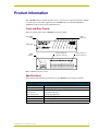
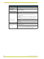
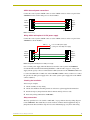
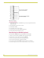
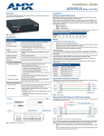
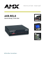
instruction manual
AXB-REL8
Axcess Relay Controller
AXlink Bus Controllers
AMX Limited Warranty and Disclaimer
AMX Corporation warrants its products to be free of defects in material and workmanship under normal use for
three (3) years from the date of purchase from AMX Corporation, with the following exceptions:
•
Electroluminescent and LCD Control Panels are warranted for three (3) years, except for the display and touch
overlay components that are warranted for a period of one (1) year.
•
Disk drive mechanisms, pan/tilt heads, power supplies, MX Series products, and KC Series products are
warranted for a period of one (1) year.
•
Unless otherwise specified, OEM and custom products are warranted for a period of one (1) year.
•
Software is warranted for a period of ninety (90) days.
•
Batteries and incandescent lamps are not covered under the warranty.
This warranty extends only to products purchased directly from AMX Corporation or an Authorized AMX Dealer.
AMX Corporation is not liable for any damages caused by its products or for the failure of its products to perform.
This includes any lost profits, lost savings, incidental damages, or consequential damages. AMX Corporation is not
liable for any claim made by a third party or by an AMX Dealer for a third party.
This limitation of liability applies whether damages are sought, or a claim is made, under this warranty or as a tort
claim (including negligence and strict product liability), a contract claim, or any other claim. This limitation of
liability cannot be waived or amended by any person. This limitation of liability will be effective even if AMX
Corporation or an authorized representative of AMX Corporation has been advised of the possibility of any such
damages. This limitation of liability, however, will not apply to claims for personal injury.
Some states do not allow a limitation of how long an implied warranty last. Some states do not allow the limitation or
exclusion of incidental or consequential damages for consumer products. In such states, the limitation or exclusion of
the Limited Warranty may not apply. This Limited Warranty gives the owner specific legal rights. The owner may
also have other rights that vary from state to state. The owner is advised to consult applicable state laws for full
determination of rights.
EXCEPT AS EXPRESSLY SET FORTH IN THIS WARRANTY, AMX CORPORATION MAKES NO
OTHER WARRANTIES, EXPRESSED OR IMPLIED, INCLUDING ANY IMPLIED WARRANTIES OF
MERCHANTABILITY OR FITNESS FOR A PARTICULAR PURPOSE. AMX CORPORATION
EXPRESSLY DISCLAIMS ALL WARRANTIES NOT STATED IN THIS LIMITED WARRANTY. ANY
IMPLIED WARRANTIES THAT MAY BE IMPOSED BY LAW ARE LIMITED TO THE TERMS OF THIS
LIMITED WARRANTY.
Table of Contents
Table of Contents
Product Information .................................................................................................1
Front and Rear Panels ...................................................................................................... 1
Specifications .................................................................................................................... 1
Connection and Wiring ............................................................................................3
Setting the DEVICE Dip Switch......................................................................................... 3
Wiring Requirements......................................................................................................... 3
Preparing captive wires............................................................................................................ 4
Wiring guidelines...................................................................................................................... 4
Connecting the Wiring ....................................................................................................... 4
AXlink data and power connections ......................................................................................... 5
Wiring AXlink with optional 12 VDC power supply ................................................................... 5
Checking the installation .......................................................................................................... 5
Relay connections.................................................................................................................... 5
Testing the installation ............................................................................................................. 6
Rack-Mounting the AXB-REL8 (optional).......................................................................... 6
System Worksheet and Installation Guide ....................................................................... 7
AXB-REL8 Axcess Relay Controller
i
Table of Contents
ii
AXB-REL8 Axcess Relay Controller
Product Information
Product Information
The AXB-REL8 Relay Controller provides remote control for up to eight relay functions. Suitable
for stand-alone or rack mount applications, the AXB-REL8 may be used with AXCESS or
AXCENT systems via the four-wire AXlink data bus.
Front and Rear Panels
The front and rear panels of the AXB-REL8 are shown in FIG. 1.
Device DIP
switch
Relay
LEDs (1-8)
AXlink LED
DEVICE
AXlink
1
3
2
5
4
6
7
8
ON
Relay contacts 1-4
(shared commons)
Relay contacts 5-8
(discrete commons)
AXlink
connector
AXP
PWR
AXM
GND
8
B
7
A
B
6
A
B
5
A
B
4
A
B
3
A
B
1
2
A
B
A
B
A
AXlink
FIG. 1 AXB-REL8 front and rear views
Specifications
The following table details the specifications for the AXB-REL8 Axcess Relay Controller.
Specifications
Dimensions (HWD)
1.51" x 5.55" x 5.45" (3.84 cm x 14.10 cm x 13.84 cm)
Enclosure
Non-glare, high-impact black matte plastic
Power Consumption
Baseline draw
• 90 mA @ 12 VDC (min)
With all 8 relays On
• 170 mA @ 12 VDC (max)
Weight
17.50 oz. (496.11 g)
Included Accessories
Metal tab strips included for external adjacent relay communing.
Optional Accessories
AC-RK Accessory Rack Kit
AXB-REL8 Axcess Relay Controller
1
Product Information
Specifications (Cont.)
Dimensions (HWD)
1.51" x 5.55" x 5.45" (3.84 cm x 14.10 cm x 13.84 cm)
Enclosure
Non-glare, high-impact black matte plastic
Power Consumption
Baseline draw
• 90 mA @ 12 VDC (min)
With all 8 relays On
• 170 mA @ 12 VDC (max)
Front Panel Components
AXlink Status indicator
AXlink LED (green and blinks to indicate AXlink communication activity and
power:
• Full-Off indicates no power is being received or the controller is not
functioning properly.
• One blink per second indicates power is active and AXlink communication is
functioning.
• Full-On indicates there is no AXlink control or activity, but power is On.
Device DIP switch
An eight-position DIP switch is used to set the device number for the
AXB-REL8.
Relay LEDs 1-8 (Red)
Illuminate when associated relay is closed. Relay LED's should match panel
control function.
Rear Panel Components
AXlink connector
Relay contacts
Four-pin captive wire receives power and information via the AXlink bus and
AXlink system controller.
Eight (normally -open) isolated two-pin relay contacts 1 A @ 28 VAC or VDC:
• Relays 1-4 can share a common if use jumper"A" pins with a tab strip
• Relays 5-8 use discrete commons (wire commons individually)
2
AXB-REL8 Axcess Relay Controller
Connection and Wiring
Connection and Wiring
Setting the DEVICE Dip Switch
The eight-position Device DIP switch is located on the front panel of the AXB-REL8 as shown in
FIG. 1 on page 1. Each device in the AXlink bus must have a unique AXlink device number.
If you later change the device number, remove and reconnect the AXlink connector.
This enters the new device number into memory. The device number takes effect only
on power-up.
The device can be 1 of the 255 devices in an Axcess, AXCENT, AXCENT2, or AXCENT3 system.
The device number must match the device assignment in the Axcess program. AMX assigns device
numbers into the following three segments:
!
Cards
!
Boxes
96 through 127
!
Panels
128 through 255
1 through 95
Set the device number by setting the DEVICE DIP switch. The device number is the total of all of
the switches in the ON (down) position. The following table shows the switch numbers and their
corresponding values.
Device DIP switch settings
Position
1
2
3
4
5
6
7
8
Value
1
2
4
8
16
32
64
128
As an example, the following DIP switch (FIG. 2) defines the AXB-REL8 as device number
97 (1 + 32 + 64 = 97).
DEVICE
ON
1
2 3 4
5 6 7 8
FIG. 2 Example device DIP switch with value of 97
Set the AXB-REL8 device number before connecting AXlink wiring. Do not install relay wiring at
this time.
Wiring Requirements
The AXB-REL8 uses a four-pin AXlink Central Controller connector for power and data. If the
distance between the AXB-REL8 and the Central Controller exceeds power consumption limits,
you must connect an optional 12 VDC power supply. Refer to the following section for more
information.
AXB-REL8 Axcess Relay Controller
3
Connection and Wiring
Do not connect power to the AXB-REL8 until the wiring is complete. If you are using a
12 VDC power supply, apply power to the AXB-REL8 only after installation is
complete.
Preparing captive wires
To connect the wiring into a captive-wire connector:
1. Strip 1/4 inch off the wire insulation for all four wires.
2. Tin 2/3 of the exposed wire.
3. Insert each wire into the appropriate captive-wire connector up to the insulation.
4. Tighten the captive screws to secure the fit in the connector.
Wiring guidelines
The AXB-REL8 requires 12 VDC power to operate properly. The Central Controller supplies
power via the AXlink cable. The maximum AXlink wiring distance between the Central Controller
and AXB-REL8 is determined by power consumption, supplied voltage, and the wire gauge used
for the cable. The following table lists wire sizes and the maximum lengths allowable between the
AXB-REL8 and the Central Controller, based on the maximum power consumption rating of 170
mA (all eight relays ON).
The maximum wiring lengths for using AXlink power are based on a minimum of 13.5 volts
available at the Central Controller's power supply.
Wiring Guidelines at 170 mA
Wire Size Maximum Wiring Length
18 AWG
690.42 feet (210.43 m)
20 AWG
436.80 feet (133.13 m)
22 AWG
272.33 feet (83.00 m)
24 AWG
171.66 feet (52.32 m)
If the AXB-REL8 is installed farther away from the control system than recommended in the above
table, connect a 12 VDC power supply to the AXlink connector on the AXB-REL8 rear panel (see
Wiring AXlink with Optional 12 VDC Power Supply).
Connecting the Wiring
The following paragraphs describe wiring connections for using the AXlink and relay connectors.
If using power from AXlink, disconnect the wiring from the control system before
wiring the AXB-REL8.
4
AXB-REL8 Axcess Relay Controller
Connection and Wiring
AXlink data and power connections
Connect the control system's AXlink connector to the AXlink connector on the rear panel of the
AXB-REL8 for data and 12 VDC power as shown in FIG. 3.
PWR +
PWR +
AXP/TX
AXP/TX
AXM/RX
AXM/RX
GND -
GND AXB-REL8
Central Controller
FIG. 3 AXlink wiring
Wiring AXlink with optional 12 VDC power supply
Connect the control system's AXlink connector to the AXlink connector on the rear panel of the
AXB-REL8 as shown in FIG. 4.
PWR (+)
Local +12 VDC power supply
(coming from the PSN power supply)
GND (-)
PWR +
PWR +
AXP/TX
AXP/TX
AXM/RX
AXM/RX
GND -
GND AXB-REL8
Central Controller
FIG. 4 Wiring AXlink with Optional 12 VDC power supply
Use a 12 VDC power supply when the distance between the control system and AXB-REL8
exceeds the limits described in the Wiring Guidelines at 170 mA table on page 4, or the power
supply current capacity cannot accommodate the 170 ma (max) draw of the AXB-REL8. Make sure
to connect the GND and +12 VDC wire on the AXB-REL8 AXlink connector end. Do not connect
the optional +12 VDC power supply wire to the control system's power supply side of the AXlink
connector (FIG. 4).
Checking the installation
After set-up is complete:
1. Check continuity of relay wiring.
2. Check cable numbers and wiring, interfaces and sources against supplied documentation.
3. Install tab strips to jumper between shared commons and clip off excess tabs.
4. Insert relay wiring terminals into AXB-REL8.
Relay connections
The relay specification is 1 A @ VAC or VDC. FIG. 5 on page 6 shows the relay wiring diagram
for the AXB-REL8. The dotted lines are used to indicate commons. Install supplied tab strips to
jumper between shared commons. Clip off excess tabs and bend strip up, away from other wiring.
AXB-REL8 Axcess Relay Controller
5
Connection and Wiring
1
2
3
4
5
A
B
A
B
A
B
RELAYS SHARING A COMMON
Jumper "A" pins with tab strip
A
B
A
B
A
6
7
B
A
B
RELAYS WITH DISCRETE COMMONS
Wire commons individually
A
8
B
FIG. 5 Relay wiring diagram
Testing the installation
1. Check AXlink status LED - it should blink once per second (see Specifications table for
AXlink status LED).
2. Relay LED lights, but source does not activate:
3. Check wiring continuity.
4. Check jumpers used for shared commons.
5. Check cable and source against supplied documentation.
6. Check operational status of interface or source.
Rack-Mounting the AXB-REL8 (optional)
To rack-mount the AXB-REL8 into the optional AC-RK Accessory Rack Kit:
1. Remove any connected relay and AXlink connectors from the rear panel.
2. Remove the two screws on the front panel of the AXB-REL8.
3. Remove the front panel and the space bracket behind the panel.
4. Place the unit in the appropriate opening in the AC-RK.
5. Place the front panel of the AXB-REL8 on the front of the rack, over the unit.
6. Fasten the front panel to the rack and to the unit with the two screws you removed.
6
AXB-REL8 Axcess Relay Controller
Connection and Wiring
System Worksheet and Installation Guide
AXB-REL8
Dealer ID#
Dealer
PO#
Job
SO#
Description
Serial#
AXP
AXM
PWR
GND
8
B
7
A
B
5
6
A
B
A
B
4
A
B
3
A
B
1
2
A
B
A
B
A
AXlink
Device #
1
2
3
4
5
Wiring
Function
Color/Pin
AMX Cable/Infc #
Source
A
B
A
B
A
B
A
B
A
B
A
6
7
B
A
B
A
8
B
AXB-REL8 Axcess Relay Controller
7
brussels • dallas • los angeles • mexico city • philadelphia • shanghai • singapore • tampa • toronto* • york
3000 research drive, richardson, TX 75082 USA • 469.624.8000 • 800.222.0193 • fax 469.624.7153 • technical support 800.932.6993
032-004-1021 6/02 ©2002 AMX Corporation. All rights reserved. AMX, the AMX logo, the building icon, the home icon, and the light bulb icon are all trademarks of AMX Corporation.
AMX reserves the right to alter specifications without notice at any time. *In Canada doing business as Panja Inc.
AMX reserves the right to alter specifications without notice at any time.