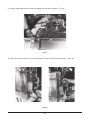
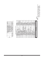
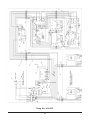
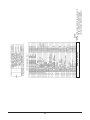
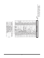
1
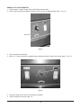
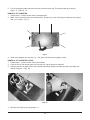
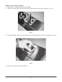
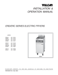
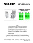
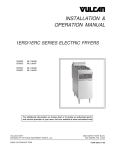
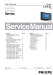
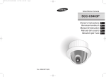
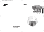
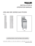
SERVICE MANUAL
GRS, GRD, AND GRC 25, 35, 45, 65
AND 85 MODEL FRYERS
MODEL
ML-52077
ML-52078
ML-52079
ML-52080
ML-52081
ML-52082
ML-52306
ML-52307
ML-52139
ML-52308
MODEL GRD35
VULCAN-HART
FORM 30912 (1-95)
COMPANY,
P.O.
BOX
696,
LOUISVILLE,
KY
40201-0696,
TEL. (502) 7 7 8 - 2 7 9 1
IMPORTANT FOR YOUR SAFETY
THIS MANUAL HAS BEEN PREPARED FOR PERSONNEL QUALIFIED TO SERVICE AND
ADJUST THE EQUIPMENT COVERED BY THIS MANUAL.
POST IN A PROMINENT LOCATION THE INSTRUCTIONS TO BE FOLLOWED IN THE
EVENT THE SMELL OF GAS IS DETECTED. THIS INFORMATION CAN BE OBTAINED
FROM THE LOCAL GAS SUPPLIER.
IMPORTANT
IN THE EVENT A GAS ODOR IS DETECTED, SHUT
DOWN UNITS AT MAIN SHUT OFF VALVE AND
CONTACT THE LOCAL GAS COMPANY OR GAS
SUPPLIER FOR SERVICE.
FOR YOUR SAFETY
DO NOT STORE OR USE GASOLINE OR OTHER
FLAMMABLE VAPORS OR LIQUIDS IN THE
VICINITY OF THIS OR ANY OTHER APPLIANCE.
WARNING
IMPROPER INSTALLATION, ADJUSTMENT,
ALTERATION OR MODIFICATION, SERVICE OR
MAINTENANCE CAN CAUSE PROPERTY
DAMAGE, INJURY OR DEATH. READ THE
INSTALLATION, OPERATING AND MAINTENANCE
INSTRUCTIONS THOROUGHLY BEFORE
INSTALLING OR SERVICING THIS EQUIPMENT.
IN THE EVENT OF A POWER FAILURE, DO NOT ATTEMPT TO OPERATE THIS DEVICE.
2
TABLE OF CONTENTS
Important Safety Information
Codes and Standards Information
Manual Uses Information
Rating Plate Information
Service Warnings
Tools Required for Servicing
Section l Service Checks & Adjustments
Section ll Service Removal and Replacement of Controls
Section lll Wiring Information
Page
Page
Page
Page
Page
Page
Pages
Pages
Pages
2
3
3
3
3
3
4-10
12-60
61-109
CODES AND STANDARDS
Vulcan-Hart Fryers are to be installed in accordance with state and local codes, or in the absence of local codes,
the National Fuel Gas Code, ANSI-Z223.1(latest edition), available from the American Gas Association, Inc.,
1515 Wilson Boulevard, Arlington, VA. 22209 and with ANSI-NFPA Standard #96 (latest edition), Vapor
Removal From Cooking Equipment, available from the National Fire Protection Association, Batterymarch
Park, Quincy, MA 02269.
HOW TO USE THIS MANUAL
This Manual is dedicated to the servicing of the GRS, GRD, and GRC Series Vulcan Gas Fryers.
The Manual is divided into 3 sections, GRS,GRD, AND GRC SERIES SERVICE CHECKS & ADJUSTMENTS,
GRS, GRD, and GRC REMOVAL AND REPLACEMENT OF COMPONENT PARTS and GRS, GRD AND GRC
WIRING INFORMATION. Refer to the Table of Contents when looking for a specific performance check or
procedure. For additional Technical assistance contact the Vulcan Hart Service Dept. at the phone number
shown on the cover of this manual. Read the following rating plate and service warnings before preforming any
service work. Refer to parts manual F30782 to identify service parts for GRS, GRD and GRC Fryers.
RATING PLATE
The rating plate stating model number, serial number, manufacturing date, gas type, voltage and amperage is
located on the inside fryer door panel.
SERVICE WARNINGS
Hot oil and parts can cause burns, use care when servicing this appliance.
If fryer is pulled from the installation area for servicing, reinstall the fryer at least 16" away form any open flame
appliance with back and sides of fryer 6" away from combustible and 0" away from noncombustible construction.
The high limit is a shut off device which senses the temperature of the appliance to prevent over heating. The
high limit operates independently and will automatically cause equipment shut down should the primary control
fail. If this situation occurs, DO NOT attempt to bypass the high limit.
TOOLS REQUIRED
The following is a listing of tools required to perform the service checks in this manual
1. Standard set of hand tools.
2. Volt Meter with a sensitivity of at least 20,000 ohms per volts.
3. Temperature tester (thermocouple or digital pyrometer).
4. Gas test kit.
3
SECTION I
GRS,GRD AND GRC SERVICE CHECKS & ADJUSTMENTS
WARNING:
WARNING:
WARNING:
UNPLUG FRYER BEFORE SERVICING.
SHUT OFF GAS BEFORE SERVICING.
CERTAIN PROCEDURES IN THIS SECTION REQUIRE ELECTRICAL TEST OR
MEASUREMENTS WHILE POWER IS APPLIED TO THE FRYER. EXERCISE EXTREME
CAUTION AT ALL TIMES. IF TEST POINTS ARE NOT EASILY ACCESSIBLE, DISCONNECT
POWER, ATTACH TEST EQUIPMENT AND REAPPLY POWER TO TEST.
VENTILATION CHECKS
NOTE:
Do not connect the fryer flue directly to the vent.
CAUTION: The vent of the appliance should be checked every 6 months for restrictions.
GAS SUPPLY CHECKS
NOTE:
If gas supply piping system is going to be tested at a test pressure of in excess of 1/2 psig (3.45 Kpa),
the fryer and its individual shut-off valve must be disconnected from the supply line. If the gas supply
pipping system is going to be tested at a test pressure equal to or less than 1/2 psig (3.45Kpa), the
individual manual shut-off valve must be closed during testing.
The fryer burners operate in conjunction with a combination gas valve pressure regulator. Verify that the valve
is set for a rating of 4" Water Column for Natural Gas and 10" Water Column for Propane Gas.
Verify that the facility pressure is at least 5" Water Column for Natural Gas and 11" Water Column for Propane.
Also verify that the gas connection pipe line is at least 1/2" for a single body fryer and
1-1/14" for a battery of fryers.
Verify that the fryer is installed in accordance with all local and state authorities having jurisdiction.
GAS CONNECTION CHECK
1. Insure that facility main gas valve is open.
2. Insure that fryer combination gas valve is open.
3. Using a soap solution check for gas leakage at all gas line connection points.
STORE LINE GAS PRESSURE CHECK
1. Connect manometer to the manual gas shut off valve pressure tap.
2. Be sure gas supply line is open and that shut off valve is open
3. Manometer reading should be at least 5 in. water column natural (7 in. for battery) and 11 in. water column
propane (12 for battery).
4. If the above is not proven instruct store owner to have pressure problem corrected before
performing any other service work to fryer(s).
4
COMBINATION VALVE GAS PRESSURE CHECK
1. Check pressure rating of appliance as stated on the fryer door.
2. Connect a manometer to the pressure tap of the gas combination valve (gas tap is marked on valve).
3. Turn on all appliance burners.
4. Open the pressure tap of the manometer.
5. The manometer reading should match the pressure rating inches water column as stated on the appliance
rating plate.
6. If pressure rating is off check the incoming store gas pressure line. If store line pressure is good continue
with the following steps.
7. Remove the regulator adjustment cap from the combination valve.
8. Turn the gas adjustment screw clockwise to increase pressure and counterclockwise to decrease pressure.
9. Adjust pressure so that manometer reading agrees with the rating plate.
ON-OFF ROCKER SWITCH (D.P.S.T.)
1. Unplug fryer.
2. Follow steps under Removal of Control Panels.
3. Note and disconnect wiring from switch.
4. With an ohm meter and switch in the "off" position measure for continuity across the (2) switch pins that were
connected to power. An ohm reading of infinity should be found.
5. With an ohm meter and switch in the "on" position measure for continuity across the (2) switch pins that were
connected to power. An ohm reading of 0 should be found.
6. If readings measured in either steps 4 or 5 do not agree with what is stated in these steps replace the switch.
SIGNAL LIGHT
1. With unit power connected follow steps for Removal of Cooker Control Panel except do not
disconnect the control panel electric supply wire harness.
2. Turn power switch "on".
3. If light fails to illuminate, with a voltage meter measure for voltage of between 110 and 120 volts
across the light connections. If voltage is not found replace light.
BURNER PILOT CHECK
1. Follow steps 1-8 under Removal of Burner.
2. Follow steps 1-3 under Removal of Burner Pilot and Orifice.
3. Examine the pilot body and orifice for clogging.
4. If clogged blow through one end of device. If clogging is still evident soak in warm water, use small probe
or contact cleaner to clear the obstruction. Do Not enlarge pilot orifice opening. If clogging still persists
install new body or orifice as required.
5. Follow steps 1-2 above in reverse to install new parts or reinstall repaired parts.
TRANSFORMER CHECK
1. Follow steps 1-6 under Accessing of Controls Inside the Control Box.
2. Follow Steps 1-4 under Removal of Transformer.
3. With a volt meter and the appliance "on", check the voltage across the load and line terminals. Voltage
should match that of the transformer markings.
EXAMPLE:
Transformer marked - PRI. 120V
SEC. 24VAC
Means that the load input reading should be 120V and the line output reading should be 24V.
4. If the readings do not match replace the transformer.
5. If readings do match but transformer problem is still suspected, check for resistance across the load terminal.
5
HI
1.
2.
3.
LIMIT CHECK
Place pyrometer in the tank 1/2" above the crumb screen in the center of the vat.
Turn fryer on.
Bypass the hi limit by running a jumper wire between pins 13 and 14 on the temperature board. Run the
appliance temperature up to between 465-470 degrees F.
4. Remove bypass jumper, observe reading, the hi limit should trip fryer heating at between the temperatures
of 435-465 degrees F. If tripping does not occur replace limit.
FRYER TEMPERATURE CALIBRATION CHECK
1. Turn fryer on and allow temperature to stabilize by letting the fryer cycle on and off, after reaching the set
temperature, at least three times.
2. Place a pyrometer sensor in the tank 1/2" above the crumb screen in the center of the vat.
3. After the stabilizing period the shortening temperature reading of the pyrometer should match the
temperature dial with in plus or minus 10 degrees for GRS Fryers and 5 degrees for GRD and GRC Fryers.
4. If readings are not in tolerance continue with the following steps.
5. Turn temperature dial to a mid range position.
6. Allow temperature to stabilize for several minutes.
7. For GRS Fryers remove temperature dial knob and with a small flat head screwdriver rotate the adjustment
screw to match pyrometer reading clockwise to increase and counterclockwise to decrease setting. One
quarter turn will change the temperature by 18 degrees.
For GRD Fryers using small flat blade screwdriver loosen the temperature control knob set screw. Without
moving the shaft rotate the knob to match the reading of the pyrometer and retighten knob.
8. Check temperature cycling again to insure proper calibration.
BASKET LIFT MICRO SWITCH (Option)
1. Follow steps 1-6 under Removal of Basket Lift Back.
2. Remove switch wiring. Engage the switch and with an ohm meter check for continuity across the common
and normally open circuits. If continuity is not shown replace the switch.
BASKET LIFT MOTOR (Option)
1. Follow steps 1-6 under Removal of Basket Lift Back.
2. Follow steps 1-7 under Removal of Basket Lift Motor.
3. With volt meter and power on check for voltage to the motor.
4. Verify that the motor voltage is proper for the unit voltage as stated on the appliance rating plate.
5. Check the motor wire connections.
6. Unplug the fryer and disconnect the motor wires at the motor terminals.
7. With ohm meter measure the resistance across the terminals. The resistance should be about 28 ohms.
8. If resistance is not correct replace the motor unit.
BASKET LIFT TIMER (Option)
1. Follow steps 1-2 under Removal of Control Panel (Solid State Construction).
2. Check for good wire connection at the terminals.
3. Push power switch "on".
4. With a volt meter check for 24vac across the input terminals of L1 and L2.
5. With a volt meter check for 24vac across the load terminals after setting the timer and pushing the timer
button. Reading should remain constant at 24vac until the timer runs out.
6. If the above readings are not achieved replace timer.
BASKET LIFT ARM ADJUSTMENT (Option)
This is only required if basket lift arm is not properly raising and lowering the fryer baskets correctly into the tank.
1. Turn the fryer off and allow it cool.
2. Remove the fryer baskets.
3. Pull lift arm from the cooker
4. Turn the adjustment bolt, by hand, to the required height.
6
FILTER INTER PLUMB DISCARD TUBE (Option)
1. Close the drain valve.
2. Place shortening discard pan under the tube plug end that will be serviced.
3. With a pipe wrench open the plugged end of the tube up.
4. Insert the clean-out rod supplied with the fryer into the opening.
5. Push the rod in and out of the tube to clear any debris that may be clogging the tube.
6. If clean out rod is not long enough, a plumber’s snake may be required to dislodge a clog.
7
SECTION I
GRS SERIES (ONLY) SERVICE CHECKS
WARNING:
WARNING:
WARNING:
UNPLUG FRYER BEFORE SERVICING.
SHUT OFF GAS BEFORE SERVICING.
CERTAIN PROCEDURES IN THIS SECTION REQUIRE ELECTRICAL TEST OR
MEASUREMENTS WHILE POWER IS APPLIED TO THE FRYER. EXERCISE EXTREME
CAUTION AT ALL TIMES. IF TEST POINTS ARE NOT EASILY ACCESSIBLE, DISCONNECT
POWER, ATTACH TEST EQUIPMENT AND REAPPLY POWER TO TEST.
CONTROL SYSTEM OVERVIEW:
1. The thermopile (T.P.) provides the total control voltage for this system.
A. One side of the T.P. is connected to the common (C) of the high limit (H.L.).
B. The other side of the T.P. is connected to the normal open (N.O.) of the H.L.
C. The "C" of a the H.L. (below the H.L. trip temperature.) is connected through the
normally closed (N.C.) contact of the H.L. through wire #3 to the combination valve
pilot connection (common).
D. The other side of the pilot valve is connected through wire #4 to wire #1 to H.L. N.O.
which holds the pilot valve voltage, closing the gas valve.
2. The thermostat controls heat to the fryer.
A. One side of the millivolt supply is connected through the H.L. system as described
above to the thermostat common (wire #2 ) of the combo valve.
B. The other side of the T.P. is connected from the "N.O." of the high limit to the
thermostat through wire #1.
C. When the thermostat calls for heat (closed circuit) power from the T.P. is then
connected to the other combination valve thermostat connection through wire #2.
D. If the H.L. trips, the T.P. is connected across the 0 OHMS, the output voltage of
the T.P. drops to 0.0 millivolts and the thermostat coil of the combination (combo)
valve drops out shutting the thermostat valve.
3. Total shutdown
A. High limit trip causes 0.0 millivolts to both coils of the combo valve, causing both
valves to close.
B. Pilot relight cannot be accomplished until oil cools sufficiently to allow H.L. to close.
C. Any wire in the system being cut or broken will cause shutdown of the system.
QUICK SYSTEMS CHECK:
1. Check MV at wire #'s1&3 and with pilot lighting procedure.
A. If good and pilot lights, then pilot combination combo and H.L. are good.
B. If 0 volts (pilot will not stay lit), check H.L. and open circuit T.P. If good (300MV)
check H.L. If the H.L. is good replace the combo valve.
C. Check for voltage at disconnected T.P. If 0 volts, replace T.P. If good (300MV)
check H.L. If H.L. good, replace combo valve.
2. Turn "On" thermostat-burners should light.
A. If no burner operation, check:
-Voltage at combo valve. If voltage is good replace valve.
- Pilot relight cannot be accomplished until oil cools sufficiently to allow H.L. to close.
B. If 0 volts, check voltage between wire #2 of combo valve and of the thermostat.
If good, check resistance of thermostat and wire #3. If no voltage, check
resistance of thermostat and wire #4. If no voltage, check resistance of wire #1 to "N.O."
of high limit.
8
SECTION I
GRD AND GRC SERIES (ONLY) SERVICE CHECKS
1 2 3 4
MV
BUR
MV PV PV GND
WARNING:
WARNING:
WARNING:
5 6 7
8
9
SEN
SPK
24V 24V W
GNDHOT TH
UNPLUG FRYER BEFORE SERVICING.
SHUT OFF GAS BEFORE SERVICING.
CERTAIN PROCEDURES IN THIS SECTION REQUIRE ELECTRICAL TEST OR
MEASUREMENTS WHILE POWER IS APPLIED TO THE FRYER. EXERCISE EXTREME
CAUTION AT ALL TIMES. IF TEST POINTS ARE NOT EASILY ACCESSIBLE, DISCONNECT
POWER, ATTACH TEST EQUIPMENT AND REAPPLY POWER TO TEST.
If erratic ignitor operation is experienced check for the following:
1. If you are experiencing system lock out, reset system by turning power switch off wait several minutes and
turn switch on.
2. Check for good metal to metal contact between the pilot bracket and main pilot burner.
3. Check that all lead connections from the ignition module to the ignitor system are solid.
4. Check that GRD (BUR) lead from the module to the pilot burner are solid and that there is not any damage
to the wiring. If damage is detected either replace the ignitor assembly or the ignitor wire with no.14-18
gauge, moisture-resistant, thermoplastic insulated wire with a min. 105 degrees C (221 degrees F.) rating.
5. Check the ceramic flame rod insulator of the ignitor for cracks or evidence of extreme heat. If one or both
of these conditions are found replace the pilot ignitor assembly.
6. Check to insure that ignitor boot is not loose or damaged.
If the above visual checks are positive the following checks should be performed using a jumper
wire and voltage meter.
CHECKING THE SPARK IGNITION CIRCUIT
WARNING:
THE IGNITION CIRCUIT GENERATES OVER 10,000 VOLTS AND ELECTRIC SHOCK CAN
RESULT. DO NOT TOUCH THE STRIPPED END OF JUMPER TO THE SPARK
TERMINAL.
NOTE: You will need a short jumper wire made from ignition cable or other heavily insulated wire.
1. Close the manual gas valve.
2. Disconnect the ignition cable at the SPARK terminal on the module.
9
3. Push power switch ON and immediately touch one end of the jumper firmly to the GND terminal on the
module. Do not touch the jumper to the SPARK terminal, but, move the free end of the jumper slowly towards
the SPARK terminal until a spark is established.
Pull the jumper slowly away from the SPARK terminal and note the length of the gap when the sparking stops.
See table below for results and action to be taken.
ARC LENGTH
ACTION
No arc or arc less than 1/8".
Verify power at module input terminal.
Replace module if power is verified.
Arc 1/8" or longer
Voltage output is OK.
If you are getting spark but the spark continues after the pilot is lit check the following.
4.
5.
6.
7.
8.
Check for ground wire and ignition cable continuity.
Check that flame rod is clean.
Check for crack in ceramic insulator again.
Check that pilot flame covers rod and is steady and blue. Adjust pilot or pilot flame if necessary.
If the above are all in good condition replace module.
PILOT CHECK (Pilot will not light)
1. Check that all manual gas valves are open, that supply tubing and pressure are good and pilot orifice is not
blocked.
2. Check electrical connections between module and pilot operator on gas combo valve.
3. With volt meter check for 24Vac across PV-MV/PV terminals on module. If voltage is good replace the combo
valve. If voltage is bad replace the module.
BURNER CHECK (Main burner will not light)
1. Check for 24Vac across the MV-MV/PV terminals. If voltage is bad replace the module.
2. Check electric connection between the module and gas combo valve. If good replace the combo valve.
COMPUTER CONTROLLER DIAGNOSTIC CHECKS
The service diagnostics for the GRC Fryer computer is divided into (2) sections NORMAL and SERVICE
DIAGNOSTICS. The normal mode is the usual operating mode of the fryer. The service mode is intended to
give the service man more information regarding the nature of the system’s failure.
NORMAL OPERATING MODE CHECKS:
SYSTEM PROBLEM
OR FAILURE
Ignition
Low temperature
lack of heat
High temperature
1st. limit comes on.
High temperature
2nd limit comes on.
Probe
Self-check
DISPLAY
SYSTEM RESPONSE
IGN. FAILURE
LOW TEMP.
Heat off
Heat off
HIGH TEMP
Heat off
CALL SERVICE
Hardware limit heat off
CALL SERVICE
CALL SERVICE
Heat off
System to back up mode
10
SERVICE MODE
Enter the service mode by pressing the product 3 and product 4 keys while turning "on" power to the fryer
computer. Display should now read "SERVICE". In this mode the following display/systems response will be
given for the noted error condition.
SYSTEMS PROBLEM
OR FAILURE
DISPLAY
SYSTEMS RESPONSE
Ignition
IGN FAILURE with
L or R for split
LO TEMP XXXF
Heat off
HI TEMP XXXF
Heat off
HI TEMP XXXF
Hardware limit, heat off
PROBE OPEN R or L
PROBE SH R or L
MICRO FAIL
MICRO FAIL
Heat off
Low temperature (lack
of heat)
High temperature
(1st limit)
High temperature
(2nd limit)
Probe
Self check
Self check
Heat off
System to backup mode
System to back up mode
SYSTEMS TEST
This menu is intended to give the servicer the ability to check the basic parts of the computer interface (i.e. the
display panel and keypad). Enter the system test mode by holding down the product 8 and 9 keys while turning
on the power for the computer. Upon entry to the system tests the message panel will read "SYSTEM TESTS".
Use up and down arrow keys to choose the following.
-VER XXX
-DISPLAY TEST
-KEYPAD TEST
Pressing "EXIT" while in the "SYSTEM TESTS" menu will exist the system test mode and return the computer
to the "NORMAL" operating mode.
SOFTWARE VERSION
The display message "VERXXX" tells the version of the software that is installed into the computer. XXX
is a code representing the software revision level. The last two digits represent minor revision sand first
digits represent major revisions. For example version 1.02 would appear as 'VER 102".
DISPLAY TEST
This allows the servicer to test the display characters. Upon entering this test a string of characters will
appear on the display panel. The servicer then uses the up and down arrow keys to scroll through the
following sets of characters:
"0123456789 @"
"ABCDEFGHIJKL"
"MNOPQRSTUVWX"
"YZ<-> * / & ? + ( )"
Press "EXIT" at any time to terminate the display test mode.
KEYPAD TEST
This allows the servicer to test for proper key functioning. Entering this test will cause the
computer to display "PRESS KEYS". After this display press each key on the keypad. When the
key is pressed the message display should match the depressed key. Pressing "EXIT" at any
time will terminate the keypad test and return the computer to the "SYSTEMS TEST" menu.
11
SECTION II
REMOVAL OF CONTROL PANEL AND REPLACEMENT OF
CONTROLS
WARNING:
WARNING:
WARNING:
UNPLUG FRYER BEFORE SERVICING.
SHUT OFF GAS BEFORE SERVICING.
CERTAIN PROCEDURES IN THIS SECTION REQUIRE ELECTRICAL TEST OR
MEASUREMENTS WHILE POWER IS APPLIED TO THE FRYER. EXERCISE EXTREME
CAUTION AT ALL TIMES. IF TEST POINTS ARE NOT EASILY ACCESSIBLE, DISCONNECT
POWER, ATTACH TEST EQUIPMENT AND REAPPLY POWER TO TEST.
CONTROL PANEL (STANDARD MILLIVOLT CONSTRUCTION)
Follow step 1 only if complete disassembly of panel is necessary. Otherwise begin with step 2.
1. Remove the thermostat knob from the control panel and disengage the (2) screws holding the
thermostat to the panel. (Fig. 1)
2. With a 1/4" socket remove (2) #8 hex head screws located in the top left and right hand corners of the control
panel. (Fig. 1)
Fig. 1
3. With a 1/4" socket remove (2) #8 sheet metal screws from the under flange of the control panel, carefully
lower the panel and the fryer door from the appliance. (Fig. 2)
Fig. 2
12
4. Reinstall panel by reversing steps 1-3.
CONTROL PANEL (ELECTRONIC IGNITION)
1. Follow steps 1 through 3 under Standard Millivolt Construction. (Fig. 3)
2. Disconnect basket lift (applicable) or main wire harness before removing the control panel and fryer door.
Fig. 3
CONTROL PANEL (SOLID STATE CONSTRUCTION)
1. Follow steps 2-3 under Standard Millivolt Construction. (Fig. 4)
2. Disconnect basket lift ( if applicable) and main wire harness before removing the control panel and fryer door.
Fig. 4
3. Reinstall panel by reversing steps 1-2.
13
CONTROL PANEL (COMPUTERIZED).
1. Follow steps 1 through 2 under Solid State Construction and disconnect the computer power
wiring harness. (Figs. 5)
Figs. 5
2. To remove the computer disengage (6) 6-32 nuts from the back of the control panel. (Fig. 6)
Fig. 6
3. Reinstall the computer panel by reversing steps 2-3.
NOTE: To avoid breakage, do not over tighten the 6-32 nuts.
14
REMOVAL OF CONTROL PANEL HOUSING
1. Follow steps 1-2 under Control Panel (Electronic ignition).
2. With a 5/16" socket remove (4) screws holding the housing to the fryer body sides. (Fig. 7)
Fig. 7
3. Note and disconnect any wiring harnesses from the housing. If millivolt fryer, pull the thermostat wire
through the access hole in the box. (Fig. 8)
Millivolt construction pull thermostat wire
through the access hole in the box.
Solid state disconnect wire harness.
Fig. 8
4. Pull housing from the fryer.
15
REMOVAL OF KX THERMOSTAT
1. Drain fry compound from the tank.
2. Follow steps 1-3 under Removal of Control Panel (Standard Millivolts) (Figs. 9)
3. Remove (2) wires from the thermostat.
Figs. 9
5. From inside tank remove (4) #8 screws using a 1/4" socket to disassemble the thermostat bulb and hi limit
clamps. (Fig. 10)
Fig. 10
16
5. From inside the fryer cabinet, follow the thermostat lead wire to the bulb packing nuts in the bottom of the
tank. With a 5/16" wrench remove the thermostat packing nut and with an 11/16" wrench remove the
thermostat bulb holding nut. (Fig.11)
Holding Nut
Packing Nut
Fig. 11
6. Pull the thermostat bulb from the fryer through the tank bottom. (Fig. 12)
Fig. 12
7. Install new thermostat by reversing steps 1-6.
17
REMOVAL OF POTENTIOMETER
1. Follow steps 1-2 under Control Panel (Solid State Construction)
2. With a small flat blade screwdriver loosen the set screw in the potentiometer knob. (Fig. 13)
Set Screw
Fig. 13
3. Pull the knob off of the panel.
4. With a 1/2" wrench remove the potentiometer holding nut from the front of the control panel. (Fig. 14)
Fig. 14
5. Remove the pot wires from the wire harness assembly.
6. Install new pot by reversing steps 1-5.
18
REMOVAL OF THERMISTOR PROBE
1. Follow steps 1-5 under Removal of Potentiometer.
2. If necessary remove burners that may be in the way of the thermistor probe hardware in the bottom of the
fryer tank. Refer to Removal of Burner.
3. With a 1/2" wrench remove the thermistor packing nut. (Figs. 15)
Figs. 15
4. With an 11/16" wrench remove the potentiometer retaining nut from the bottom of the tank. With a 1/4" socket
from inside the fryer tank remove (2) #8 sheet metal screws. (Figs. 16)
Retaining Nut
Figs. 16
19
5. Pull the thermistor probe lead from the fryer tank and install new Thermistor probe by reversing
steps 1-6. (See Fig. 12)
REMOVAL OF COMPUTER
1. Follow steps 1-2 under Control Panel (Computerized)
2. Make sure all wire harnesses are disconnected. Remove (6) screw securing the computer to the panel
with a 1/4" socket. (Fig. 17)
Fig. 17
3. Install new computer by reversing 1-2. Use loctite and do not over tighten screws.
REMOVAL OF INDICATOR LIGHTS
1. Follow steps 1-2 under Control Panel (Solid State).
2. From the rear of the control panel unscrew the wire cap of light to be replaced.
3. Squeeze the tabs on both sides of the indicator light being replaced and pull the light out through the
front of the panel. (Figs. 18)
Figs. 18
4. Reinstall new light by reversing steps 1-3.
20
REMOVAL OF ROCKER SWITCHES
1. Follow steps 1-2 under Control Panel (Solid State).
2. From rear of control panel note and remove wire leads from the rocker switch terminals. (Fig. 19)
Fig. 19
3. Press tabs on both sides of the switch and push the switch through the front of the control panel. (Fig. 20)
Fig. 20
4. Reinstall new switch by reversing steps 1-3.
21
REMOVAL OF HIGH LIMIT
1. Drain shortening from the fryer.
2. Open fryer door and disengage hi limit wire harness located below the control housing to the left
side of the fryer. (Fig. 21)
Fig. 21
3. With a flat blade screwdriver note and remove (3) wire leads from the high limit. (Fig. 22)
Fig. 22
22
4. Remove (2) #8 sheet metal screws from the bracket holding the limit in place. (Fig.23)
Fig. 23
5.
From inside the fryer tank, with a 1/4" socket remove (4) #8 screws and holding brackets for the limit
bulb. (Fig. 24)
Fig. 24
23
6. If necessary for ease of accessibility follow steps 1-8 under Removal of Burner and take out any
burner in the way of the limit bulb packing and retaining nuts.
7. With a 5/16" wrench remove the limit packing nut from the tank bottom. (Fig. 25)
Fig. 25
8. With an 11/16" wrench remove the limit retaining nut from the tank bottom. (Fig. 26)
Fig. 26
24
9. Pull the limit bulb out from underneath the fryer tank. (See Fig. 86)
10. Reinstall new high limit by reversing steps 1-9.
REMOVAL OF THERMOPILE (STANDARD MILLIVOLT SYSTEM)
1. Follow steps 1- 3 under Control Panel (Standard Millivolt Construction)
2. With a 1/4" socket disengage (4) #8 hex head screws, pull the thermostat wire from the housing and remove
the control housing. (Figs. 27)
Figs. 27
3. From the high limit disengage the closed and normally open thermopile wire leads. (Fig. 28)
Fig. 28
25
4. Refer to steps 1-8 under removal of burner and remove burners as required to access the
thermopile bracket and its hardware.
5. Slide the control housing heat shield down. (Fig. 29)
Fig. 29
6. With a 1/2" wrench remove the pilot tubing from the pilot assembly. (Fig. 30)
Fig. 30
26
7. With an offset flat blade screwdriver remove the pilot assembly from the mounting bracket. (Fig. 31)
Fig. 31
8. With a 1/2" wrench remove the thermopile from the pilot assembly. (Fig. 32)
Fig. 32
9. Reinstall new thermopile by reversing steps 1-8.
27
REMOVAL OF PILOT
1. Follow instructions for the Removal of Thermopile.
2. With a 1/2" wrench remove the hex nut on the bottom of the pilot and disconnect the pilot tube. (Figs. 33)
3. With an offset flat blade screwdriver remove the pilot assembly bracket from the fryer. (Figs. 33)
Figs. 33
4. Install the new pilot by reversing steps 1-4.
REMOVAL OF IGNITOR ASSEMBLY (SOLID STATE AND ELECTRONIC IGNITION ONLY)
1. Follow steps 1- 3 under Control Panel (Solid State Construction).
2. Note and disengage wire harnesses, with a 5/16" socket remove (4) screws securing the control housing
to the fryer and pull the housing off of the fryer. (Figs. 34)
Figs. 34
28
Figs. 34
3. Refer to steps 1-8 under Removal of Burners and disassemble burners as required to access the ignitor
assembly for servicing.
4. Slide the control housing heat shield down. (Fig. 29)
5. Remove the ignitor boot. (Fig. 35)
Fig. 35
6. Follow steps 6 and 7 under Removal of Thermopile.
7. With a 1/2" wrench remove the ignitor assembly.
8. Install new pilot assembly by reversing steps 1-7.
29
REMOVAL OF GAS COMBO VALVE
1. Shut off all gas and electrical power to the unit.
2. Open fryer door and locate valve. (Fig. 36)
Fig. 36
3. Follow steps 1-8 under the Removal of Burners and disassemble any burner obstructing your working area
for the combo valve.
4. Note and remove all combination valve wiring.
5. With a 7/16" wrench loosen the pilot tube compression nut. (Fig. 37)
Fig. 37
30
The next several steps may require the removal of the Discard drain tubes on fryers with filtering systems.
If this applies to the fryer being serviced refer to steps 1-7 under Removal of Filter Discard Tubes.
6. With a 3/4" wrench remove the gas line compression elbow fitting. (Fig. 38)
Fig. 38
7. With channel locks disconnect union in gas line leading from combo valve to the burner manifold and lift
valve out of the fryer. (Fig. 39)
Union Shown from
Union
Back
Back of
Of Fryer
Fryer
Fig. 39
31
8.
9.
10.
11.
12.
Note and remove any old fittings left on the valve. Keep them for reassembly to the new valve.
Install the old fittings removed in step 8 to the new valve.
Install the new valve by reversing steps 1- 7.
Insure all wiring and gas lines are securely installed.
Check system with soap and water solution for gas leakage.
REMOVAL BURNER
1. Follow steps 1-3 under Removal of Control Housing (Millivolts).
2. In the GRD and GRC Series Fryer disconnect the control housing harness plug and remove the housing
from the fryer. For the GRS Series Fryer carefully lower the housing out of the way without removing or
kinking the KX thermostat wiring.
3. With a 5/16" socket remove (4) 10-24 screws holding the heat shield in place.
4. Slide the heat shield down to expose the burner mounting screws. (Fig. 40)
Fig. 40
32
5. With a 1/2" socket loosen (2) bolts that attach the burner to the mounting frame. (Fig. 41)
Fig. 41
6. Slide the heat shield back up to its original position.
7. If the fryer is equipped for filtering the discard tube(s) may need to be disconnect at this point. Refer to steps
1-7 under Removal of Discard Tube(s).
8. With (2) hands grasp the burner body and push it upward over the bullet nose pilot. Then tilt the burner head
back and pull the burner out of the fryer cabinet. (Fig. 42)
Fig. 42
9. Reinstall burner by reversing steps 1-8.
33
BULLET NOSE BURNER ORIFICE REPLACEMENT
1. Follow steps 1-8 under Replacement of Burner.
2. Disconnect the burner orifice top from bullet with a 5/16" wrench. The bullet body may be removed with
channel locks. (Figs. 43)
Figs. 43
3. Install new orifice by reversing steps 1-2.
REMOVAL OF FILTER DISCARD TUBE(S) (FILTER INTER PLUMB BATTERY FRYERS)
1. Close all fryer drain ball valves.
2. Place a shortening discard pan under section of the inter plumb being disconnected.
3. With a 7/16" deep throat socket remove the discard tube clamp hardware and the
stainless steel collar. Retain all parts for reassembly. (Figs. 44)
Note: GR85 and some filter interplumb fryers are equipped with flange mounted discard tubes which
require the removal of (2) bolts and a gasket.
Figs. 44
34
4. Separate the discard tube by sliding the rubber collar down one side of the drain tube. (Fig. 45)
Rubber
Collar
Fig. 45
5. Move the discard pan under the ball valve.
6. With the 7/16" socket remove the clamp hardware securing the tube to the ball valve assembly. Also if the
tube/extension section is located at the end of a battery to facilitate an RO Frymate using a 5/16" socket
remove (1) bolt mounting the tube/extension bracket to the fryer base frame. (Fig. 46)
Fig. 46
35
REMOVAL OF POWER SUPPLY BOX (ELECTRONIC IGNITION AND BASKET LIFT MODELS)
1. Disconnect gas line and pull out so that the back is accessible.
2. Disconnect the supply box wire harness (Fig. 47)
Fig. 47
3. From the front of the unit follow steps 1-5 under Removal of ignitor assembly.
4. From rear of unit with 7/16" socket and wrench remove the (2) nuts and bolts holding the supply box to the
unit base frame. (Fig. 48) Note: In the GR25 fryer, the supply box is mounted vertically in the right rear
corner of the appliance. To lower the box remove the holding screw on the bracket.
Fig. 48
36
5. Drop the supply box housing out of the bottom of the fryer.
6. To access the controls with a 5/16" socket remove (2) screws from the power supply box
top cover. (Fig. 49)
7. Reinstall housing by reversing steps 1-6.
REMOVAL OF IGNITOR MODULE
1. Follow steps 1- 3 under Control Panel (Solid State Construction).
2. Follow steps 1-5 under Removal of Supply Box Housing.
3. With a 5/16" socket remove (2) screws and open the lid to the supply housing. (Fig. 49)
Fig. 49
4. Note and remove all wiring from the ignitor module terminals. (Figs. 50)
Figs. 50
37
5. With a 1/4" socket remove (4) #8 sheet metal screws and pull module from the housing. (Fig. 51)
Fig. 51
6. Reinstall new module by reversing steps 1- 5.
REMOVAL OF TRANSFORMER
1. Follow steps 1- 6 for the Removal of the Supply Box Housing
2. Follow steps 1-2 under Access of Controls Inside the Supply Box.
3. Disconnect all wiring associated with the transformer. Note that "C" models will have
(2) transformers (Figs. 52)
"S and D" Models
"C" Models
Figs. 52
38
4. With 1/4" socket remove (2) screws securing the transformer to the control box. (Fig. 53)
Fig. 53
5. Install new transformer by reversing steps 1-4.
REMOVAL OF ELECTRICAL SUPPLY CORD
Note: The power supply line for a fryer with filter inter plumb is located in the rear of appliance housed in a junction
box. Disengage (2) screws mounting the cover to the box, then remove the cord by following steps 3-5 below.
1. Follow steps 1-6 under Removal of Supply Box.
2. Follow steps 1-2 under Access of Controls Inside the Supply Box.
3. From the rear of the box with a flat blade screwdriver remove (2) screws holding the cord mounting clamp
to the box. (Figs. 54)
Supply Box
Filter Junction Box
Figs. 54
39
4. From inside the box disconnect wiring associated with the supply cord.
5. Install the new power supply cord by reversing steps 1-4.
REMOVAL OF BASKET LIFT BACK (OPTIONAL ACCESSORIES)
1. Remove all baskets and basket support racks from tank.
2. Drain appliance tank, disconnect unit power and tipping restraint. Move appliance to an area where the
back is completely accessible.
3. Remove the basket lift arm. (Fig.55)
Fig. 55
4. Remove (14) screws from the upper back of the basket assembly using a 1/4" socket. (Fig. 56)
Fig. 56
40
5. Lift back up and over the lift mechanism. (Fig. 57)
Fig. 57
6. Disconnect the gas line and remove the lower basket lift back by disengaging (2) screws at each lower side
of the cover and (2) screws from each lower back corner using a 1/4" socket. (Fig. 58)
Fig. 58
41
7. To reinstall basket back panels reverse steps 1-6.
REMOVAL OF LIFT ROD MECHANISM
1. Follow steps 1-6 under Removal of Basket Lift Backs
2. With a 1/2" wrench remove the nut that attaches the lift rod to the lift bar. (Fig. 59)
Fig. 59
3. With a 5/16" socket remove (6) screws from the rod mechanism holding bracket. (Fig. 59)
4. Install new lift rod assembly by reversing steps 1-3.
REMOVAL OF BASKET LIFT MOTOR (OPTIONAL ACCESSORY)
1. Follow steps 1-6 under Removal of basket lift backs.
2. Follow steps 1-2 under Removal of lift rod mechanism.
3. Note and remove wiring from the cam switch. (Fig. 60)
Fig. 60
42
4. With 5/16" socket remove (2) nut holding the cam lift bracket to the fryer back. (Fig. 61)
Fig. 61
5. Remove motor wiring. (Fig. 62)
Fig. 62
43
6. With flat blade screwdriver remove (2) screws holding the motor to the cam bracket assembly.
(Fig. 63)
Fig. 63
7. Remove the motor from the cooker. To install new motor reverse steps 1-6.
8. Make certain that all wiring is clear from motor cam shaft (wire ties may be required).
REMOVAL OF BASKET LIFT CAM SWITCH (OPTIONAL ACCESSORY)
1. Follow steps 1-6 under Removal of Basket Lift Backs
2. Note and remove wiring. With a standard flat blade screwdriver and a 5/16" wrench remove (2) screws and
holding nuts from the cam switch. (Fig.64)
3. Reinstall by reversing steps 1-2
Fig. 64
44
REMOVAL OF BASKET LIFT CAM (OPTIONAL ACCESSORY)
1. Follow steps 1-6 under Removal of Basket Lift Back.
2. With a 1/2" wrench or socket remove the lift bar and cam assembly holding nut. (Fig. 65)
Fig. 65
3. With an allen wrench loosen the cam set screw. (Fig. 66)
Fig. 66
4. With an offset flat blade screwdriver remove the screws mounting the cam to the lift bar. (Fig. 65)
5. Pull the cam from the fryer. Install new cam by reversing steps 1-5.
45
REMOVAL OF TANK ASSEMBLY
If the fryer is equipped with automatic basket lifts the lift arm(s) must be removed from the fryer back before the
tank can be removed.
1. Remove fryer baskets and crumb screen. (Figs. 67)
Figs. 67
2. Remove basket hanger. (Fig. 68)
Fig. 68
46
3. If a fryer battery is involved, with a utility knife split the silicon sealant from around the grease strip between
the tanks and remove the stainless grease strip, then split the tank sections apart with a utility knife
(Fig. 69)
Fig. 69
4. Follow steps 1-4 under Removal of KX Thermostat (Millivolts) or 1-2 under Removal of Control Panel
(Electronic Ignition) as required for type fryer to be serviced. If fryer is using KX thermostat, secure the KX
thermostat body between the fryer burners so that it will not fall when the tank assembly is lifted from
the fryer. (Fig. 70)
Fig. 70
47
5. Follow steps 1-4 under Removal of Control Housing.
6. Follow steps 1-7 under Removal of Discard Tube(s).
7. For D and C models with a 7/16" socket and wrench remove (2) nuts from under base frame that secure the
manifold assembly to the frame. For S models with a 3/8" socket remove (1) screw securing the manifold
Vee bracket to the base frame. (Fig. 71)
D and C Model Fryers
S Model Fryers
Fig. 71
8. With a 5/16" socket remove (2) screws from the top flue area that secure the tank back
to the flue wrap. (Fig. 72)
Fig. 72
48
9. With a 13/16" wrench disconnect the compression elbow from the gas inlet tube. (Fig. 73)
Fig. 73
10. With 5/16" remove (4) screws holding the heat shield in place. (See Fig. 48)
11. Slide the heat shield down. (See Fig. 48)
12. If fryer is inter plumb equipped cut the wire ties holding the oil refill lines together. (Fig. 74)
If fryer is without inter plumb, skip to step 15.
Fig. 74
49
13. Disconnect micro switch. (Fig. 75)
Fig. 75
14. With a 13/16" wrench disconnect the oil refill coupling. (Fig. 76)
Fig. 76
50
15. Grasp tank from the back at the top of the flue wrap area and lift the entire tank assembly out of the fryer body.
Note that on D and C models the heat shield insulation may catch on the body frame. If this occurs the tank
assembly will not lift out of the unit. Set the tank back into the fryer body and try to align the heat shield to
keep the insulation from catching. (Fig. 77)
Fig. 77
With tank now out side of the fryer body position the tank onto its back so that the component parts may be
removed for reassembly onto the new tank.
16. With a 1/2" socket loosen the bolts holding the burners and insulation box in place. (Fig. 78)
Fig. 78
51
17. Remove the burner insulation box. (Fig. 79)
Fig. 79
18. With flat blade screwdriver remove the pilot bracket. (Fig. 80)
Fig. 80
52
19. If servicing a D or C model with a 5/16" wrench remove the hi limit packing nut. For S models use a 1/2"
wrench. (Fig. 81)
Fig. 81
20. With an 11/16" wrench remove the compression nut securing the limit bulb to the tank. (Fig. 82)
Fig. 82
53
21. With an 1/2" wrench remove the thermistor or thermo bulb packing nut. (Fig. 83)
Fig. 83
22. With an 11/16" wrench remove the compression nut holding the thermistor or thermo
bulb to the tank. (Fig. 84)
Fig. 84
54
23. With a 1/4" socket from inside the fryer tank remove the hardware and mounting clips holding
the hi limit and thermistor/thermostat bulb to the tank. (Figs. 85)
Figs. 85
24. Pull both the termistor and hi limit probes through the tank bottom and remove them from
the fryer. (Figs. 86)
High Limit
Thermistor/Thermo Bulb
Figs. 86
55
25. With a 1/2" wrench remove (4) bolts securing the manifold bracket to the tank assembly. (Fig. 87)
Fig. 87
26. For fryers housing a filter station with a quick disconnect from the front of unit with a 7/16" socket and
wrench remove the "U" bolt securing the disconnect line to the tank assembly. (Fig. 88)
Fig. 88
56
27. Remove the pull rod handle. (Fig. 89)
Fig. 89
28. With a 7/16" socket remove all the pull rod hardware from the micro switch assembly. (Fig. 90)
Fig. 90
57
29. Pull the rod up through the mounting bracket and out of the fryer. (Fig. 91)
Fig. 91
30. Pull the manifold assembly from the fryer. (Fig. 92)
Fig. 92
58
31. With an adjustable wrench remove the elbow from the tank assembly. (Fig. 93)
Fig. 93
32. With a 3/8" socket remove (2) nuts holding the oil return line to the tank assembly. (Figs. 94)
Figs. 94
59
33. With a pipe wrench remove the remove the drain valve and drain pipe assembly from the tank. (Fig 95)
Fig. 95
34. With a 3/8" socket remove (4) screws securing the flue box to the tank assembly. (Fig. 96)
Fig. 96
35. Reverse steps 16-34 to install parts removed from the tank onto the new tank.
36. Reverse steps 1-15 to install the tank assembly.
60
SECTION lll
WIRING INFORMATION
61
Drwg. No. 419357-1
62
63
RS W/MILLIVOLT SYSTEM
419999–2
Drwg. No. 419357-2
64
65
RS W/MILLIVOLT SYS & DUAL B.L.
419999–2
1
▲
WIRE COLOR IS WHITE IN 120 VOLT UNITS.
208 VOLT UNITS USE THE RED WIRE.
230 VOLT UNITS USE THE BLUE WIRE.
CAP THE UNUSED WIRE WITH WIRE NUT.
NOTE:
D1
Drwg. No. 419357-3
66
67
RS W/MILLIVOLT SYS & SGL B.L.
419999–2
1
▲
WIRE COLOR IS WHITE IN 120 VOLT UNITS.
208 VOLT UNITS USE THE RED WIRE.
230 VOLT UNITS USE THE BLUE WIRE.
CAP THE UNUSED WIRE WITH WIRE NUT.
NOTE:
D1
Drwg. No. 419322-1
68
69
RS W/E.I.
419999–2
1
▲
WIRE COLOR IS WHITE IN 120 VOLT UNITS.
208 VOLT UNITS USE THE RED WIRE.
230 VOLT UNITS USE THE BLUE WIRE.
CAP THE UNUSED WIRE WITH WIRE NUT.
NOTE:
D1
Drwg. No. 419322-2
70
71
RS W/E.I. & DUAL B.L.
419999–2
1
▲
WIRE COLOR IS WHITE IN 120 VOLT UNITS.
208 VOLT UNITS USE THE RED WIRE.
230 VOLT UNITS USE THE BLUE WIRE.
CAP THE UNUSED WIRE WITH WIRE NUT.
NOTE:
D1
Drwg. No. 419322-3
72
73
RS W/E.I. & SGL B.L.
419999–2
1
▲
WIRE COLOR IS WHITE IN 120 VOLT UNITS.
208 VOLT UNITS USE THE RED WIRE.
230 VOLT UNITS USE THE BLUE WIRE.
CAP THE UNUSED WIRE WITH WIRE NUT.
NOTE:
D1
Drwg. No. 419323-1
74
75
RS W/MELT CYCLE
419999–2
1
▲
WIRE COLOR IS WHITE IN 120 VOLT UNITS.
208 VOLT UNITS USE THE RED WIRE.
230 VOLT UNITS USE THE BLUE WIRE.
CAP THE UNUSED WIRE WITH WIRE NUT.
NOTE:
D1
Drwg. No. 419323-2
76
77
RS W/MELT CYCLE & DUAL B.L.
419999–2
1
▲
WIRE COLOR IS WHITE IN 120 VOLT UNITS.
208 VOLT UNITS USE THE RED WIRE.
230 VOLT UNITS USE THE BLUE WIRE.
CAP THE UNUSED WIRE WITH WIRE NUT.
NOTE:
D1
Drwg. No. 419323-3
78
79
RS W/MELT CYCLE & SGL B.L.
419999–2
1
▲
WIRE COLOR IS WHITE IN 120 VOLT UNITS.
208 VOLT UNITS USE THE RED WIRE.
230 VOLT UNITS USE THE BLUE WIRE.
CAP THE UNUSED WIRE WITH WIRE NUT.
NOTE:
D1
Drwg. No. 419318-1
80
81
RS W/EI, MELT CYCLE
419999–2
1
▲
WIRE COLOR IS WHITE IN 120 VOLT UNITS.
208 VOLT UNITS USE THE RED WIRE.
230 VOLT UNITS USE THE BLUE WIRE.
CAP THE UNUSED WIRE WITH WIRE NUT.
NOTE:
D1
Drwg. No. 419318-2
82
83
RS W/EI, MELT CYCLE & DUAL B.L.
419999–2
1
▲
WIRE COLOR IS WHITE IN 120 VOLT UNITS.
208 VOLT UNITS USE THE RED WIRE.
230 VOLT UNITS USE THE BLUE WIRE.
CAP THE UNUSED WIRE WITH WIRE NUT.
NOTE:
D1
Drwg. No. 419318-3
84
85
RS W/EI, MELT CYCLE & SGL B.L.
419999–2
1
▲
WIRE COLOR IS WHITE IN 120 VOLT UNITS.
208 VOLT UNITS USE THE RED WIRE.
230 VOLT UNITS USE THE BLUE WIRE.
CAP THE UNUSED WIRE WITH WIRE NUT.
NOTE:
D1
Drwg. No. 419340-1
86
87
RD W/O E.I.
1
▲
WIRE COLOR IS WHITE IN 120 VOLT UNITS.
208 VOLT UNITS USE THE RED WIRE.
230 VOLT UNITS USE THE BLUE WIRE.
CAP THE UNUSED WIRE WITH WIRE NUT.
NOTE:
D1
Drwg. No. 419340-2
88
89
RD W/DUAL B.L. W/O E.I.
1
▲
WIRE COLOR IS WHITE IN 120 VOLT UNITS.
208 VOLT UNITS USE THE RED WIRE.
230 VOLT UNITS USE THE BLUE WIRE.
CAP THE UNUSED WIRE WITH WIRE NUT.
NOTE:
D1
Drwg. No. 419340-3
90
91
RD W/SGL B.L. W/O E.I.
1
▲
WIRE COLOR IS WHITE IN 120 VOLT UNITS.
208 VOLT UNITS USE THE RED WIRE.
230 VOLT UNITS USE THE BLUE WIRE.
CAP THE UNUSED WIRE WITH WIRE NUT.
NOTE:
D1
Drwg. No. 419337-1
92
93
RD W/E.I.
1
▲
WIRE COLOR IS WHITE IN 120 VOLT UNITS.
208 VOLT UNITS USE THE RED WIRE.
230 VOLT UNITS USE THE BLUE WIRE.
CAP THE UNUSED WIRE WITH WIRE NUT.
NOTE:
D1
Drwg. No. 419337-2
94
95
RD W/E.I. & DUAL B.L.
1
▲
WIRE COLOR IS WHITE IN 120 VOLT UNITS.
208 VOLT UNITS USE THE RED WIRE.
230 VOLT UNITS USE THE BLUE WIRE.
CAP THE UNUSED WIRE WITH WIRE NUT.
NOTE:
D1
Drwg. No. 419337-3
96
97
RD W/E.I. & SGL B.L.
1
▲
WIRE COLOR IS WHITE IN 120 VOLT UNITS.
208 VOLT UNITS USE THE RED WIRE.
230 VOLT UNITS USE THE BLUE WIRE.
CAP THE UNUSED WIRE WITH WIRE NUT.
NOTE:
D1
Drwg. No. 419564-1
98
99
RC MANUAL W/O BASKETLIFT
2
▲
1
▲
WIRE COLOR IS WHITE IN 120 VOLT UNITS.
208 VOLT UNITS USE THE RED WIRE.
230 VOLT UNITS USE THE ORANGE WIRE.
CAP THE UNUSED WIRE WITH WIRE NUT.
WIRE COLOR IS WHITE IN 120 VOLT UNITS.
208 VOLT UNITS USE THE RED WIRE.
230 VOLT UNITS USE THE BLUE WIRE.
CAP THE UNUSED WIRE WITH WIRE NUT.
NOTE:
D1
Drwg. No. 419564-2
100
101
RC MANUAL W/DUAL B.L.
2
▲
1
▲
WIRE COLOR IS WHITE IN 120 VOLT UNITS.
208 VOLT UNITS USE THE RED WIRE.
230 VOLT UNITS USE THE ORANGE WIRE.
CAP THE UNUSED WIRE WITH WIRE NUT.
WIRE COLOR IS WHITE IN 120 VOLT UNITS.
208 VOLT UNITS USE THE RED WIRE.
230 VOLT UNITS USE THE BLUE WIRE.
CAP THE UNUSED WIRE WITH WIRE NUT.
NOTE:
D1
Drwg. No. 419564-3
102
103
RC MANUAL W/SINGLE B.L.
2
▲
1
▲
WIRE COLOR IS WHITE IN 120 VOLT UNITS.
208 VOLT UNITS USE THE RED WIRE.
230 VOLT UNITS USE THE ORANGE WIRE.
CAP THE UNUSED WIRE WITH WIRE NUT.
WIRE COLOR IS WHITE IN 120 VOLT UNITS.
208 VOLT UNITS USE THE RED WIRE.
230 VOLT UNITS USE THE BLUE WIRE.
CAP THE UNUSED WIRE WITH WIRE NUT.
NOTE:
D1
Drwg. No. 419366-1
104
105
RC W/ELECT, IGN., W/O B.L.
2
▲
1
▲
WIRE COLOR IS WHITE IN 120 VOLT UNITS.
208 VOLT UNITS USE THE RED WIRE.
230 VOLT UNITS USE THE ORANGE WIRE.
CAP THE UNUSED WIRE WITH WIRE NUT.
WIRE COLOR IS WHITE IN 120 VOLT UNITS.
208 VOLT UNITS USE THE RED WIRE.
230 VOLT UNITS USE THE BLUE WIRE.
CAP THE UNUSED WIRE WITH WIRE NUT.
NOTE:
D1
Drwg. No. 419366-2
106
107
RC W/ELECT, IGN., & DUAL B.L.
2
▲
1
▲
WIRE COLOR IS WHITE IN 120 VOLT UNITS.
208 VOLT UNITS USE THE RED WIRE.
230 VOLT UNITS USE THE ORANGE WIRE.
CAP THE UNUSED WIRE WITH WIRE NUT.
WIRE COLOR IS WHITE IN 120 VOLT UNITS.
208 VOLT UNITS USE THE RED WIRE.
230 VOLT UNITS USE THE BLUE WIRE.
CAP THE UNUSED WIRE WITH WIRE NUT.
NOTE:
D1
Drwg. No. 419366-3
108
109
RC W/ELECT, IGN. & SINGLE B.L.
2
▲
1
▲
WIRE COLOR IS WHITE IN 120 VOLT UNITS.
208 VOLT UNITS USE THE RED WIRE.
230 VOLT UNITS USE THE ORANGE WIRE.
CAP THE UNUSED WIRE WITH WIRE NUT.
WIRE COLOR IS WHITE IN 120 VOLT UNITS.
208 VOLT UNITS USE THE RED WIRE.
230 VOLT UNITS USE THE BLUE WIRE.
CAP THE UNUSED WIRE WITH WIRE NUT.
NOTE:
D1
110
111
FORM 30912 (1-95)
112