1
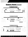
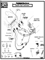
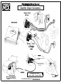
A
A
A
A
introduction
CONGRATULATIONS
On Your purchase of a new MTX
Thunder Amplifier! MTX has long been
the industn/ leader in mobile enclosures
and speakers, and we have reached
new heights with the development of the
new MTX Thunder amplifiers. You
couldn’t have chosen a more reliable,
powerful, or better performing amplifier
- In fact, we back up every Thunder
amplifier with a three-Year warranty if
installed by an authorized MTX retailer
(see the warrano/ statement on page 33).
Your new MTX Thunder amplifier was
designed, built and thoroughly tested at our
state-of-the-art electronics manufacturing
facility in Phoenix, Arizona. We manufacture
every amplifier using the latest Intelligent
Surface Mount Technology. Some of the
advantages of the new design are its significant improvements to the amplifier’s electrical
and mechanical properties. ISMT devices
feature substantially shorter internal and
external lead lengths. This reduces stray
capacitance and inductance, which results in
cleaner and more accurate musical reproduction with significantly less noise interference.
The ISMT mounter produces amplifier boards
with smaller and lighter components, which
are more resistantto vibrations inherent in the
automotive environment.
A word about power ratings. It is important for you
to know how they stack up. MTX has chosen the
most honest, most conservative way to rate our
amps. We show you the RMS power; at 12.5 volts,
and dynamic power at 14.4 volts. However, we go
above and beyond the call of duty We test each
amplifier. The technician records the “actual”
power output, and records this number on your
Certified Performance Certificate. The amplifier
must meet or exceed the rated specification
before we’ll ship it. No questions. No exceptions.
We want to ensure You get continuous high
performance from Your MTX Thunder
amplifier, so we recommend that you have it
professionally installed by Your authorized
MTX dealer.
HOW TO USE THIS MANUAL
If You are installing this amplifier Yourself, we
recommend that You read the manual coverto-cover before you install it. Familiarize
Yourself with the features and details on the
input and output panels. Make sure You have
all the equipment You need. Then follow the
step-by-step installation instructions included.
Sample installation diagrams may be found
on our website:
WWW.MTXAUOIO.COM
If You have any questions, write or call us:
MTX
4545 E. Baseline Rd.
Phoenix, AZ 85040
l-602-438-4545
I-800~CALL-MTX
technicalQmtxaudio.com
www.mtxaudio.com
Register Your warranty online
Features
Unique rubber Insulated Iso-Fe@
(Patent# 5521,792)
Nickel-elated. heavv dutv terminal block tvoe connectors
Speaker and low level inputs
lnout select 2CH / 4CH switch on Thunder4244 functions as a built-in Y connector
Color-coded wire harness for speaker-level input installation
Smart-EngagerM auto-turn on for easy integration with factory head units
Built-in. defeatable18dBloctave HP/LP crossover at 85 Hz
Thunder4244 Front channel crossover is a defeatablel8dBloctave. high pass, at 85Hz
Adjustable input sensitivity
Bridgeable, multi-channel circuit design
Regulated PWM Mosfet Switching Power Supply
New, more reliable high powerediransformers
Buffered. isolated outoutfor daisv chainino multiole amolifiers
Pure
N-Channel
Design
’
Intelligent Surface Mount Technology
Class A 100% discrete driver circuit topology
Real Bme Computerized Protection Circuit
Anti-Shock PCB mounting design
Acoustically Seamless Turn-On/Turn-Off
Smzcifications
Thunder4122
Thunder4202
RMS Power measured at 12.5 Volts DC:
30 Watts x 2 mto a 4 Ohm load wrth less than 1% THD
60 Watts x 2 into a 2 Ohm load with less than 1% THO
120 Watts brrdged into a 4 Ohm load with less than 1% THD
RMS Power measured at 12.5 Volts DC:
50 Watts x 2 into a 4 Ohm load with less than 1% THO
100 Watts x 2 into a 2 Ohm load with less than 1% THO
200 Watts bridged into a 4 Ohm load with less than 1% THO
Dynamic Power measured at 14.4 Volts DC:
50 Watts x 2 into a 4 O h m load
80 Watts x 2 into a 2 O h m load
200 Watts bridged into a 4 Ohm load
Dynamic Power measured at 14.4 Volts DC:
85 Watts x 2 into a 4 Ohm load
140 Watts x 2 into a 2 Ohm load
280 Watts brrdged into a 4 Ohm load
Signal to Noise Ratio: 1OOdEt A-Weighted (Referenced to Rated
PWR at IVRMS Input Sensitivity1
Damping Factor: ,200
Frequency Response: 20-20.000 Hz +.25dB
Defeatable 18 dB/octave crossover at85 Hz. selectable for high pass. low
pass.
Signal to Noise Ratro: IOOdB A-Weighted
(Referenced to Rated PWR at 1VRMSInput Sensitrvityl
Damping Factor: ,200
Frequency Response: 20-20.000 Hz ?.25dB
Defeatable 18 dB/octave crossover at 85 Hz, selectable for
high pass,
pass.
Dimensions: 5.63” x 9.75” x 2” l14.3cm x 24.8cm x 5.lcm)
7.98” x 9.75” x 2.1” (20.3cm x 24.8cm x 5.3cm) Including lsoFeetTM
Dimensions: 7” x 9.lY x 2” (17.8cm
9.3” x 9.lY x 2.1” (238cm x 24.8cm
Thunder4244
RMS Power measured at 12.5 Volts DC:
45 Watts x 4 into a 4 Ohm load with less than 1% THO
60 Watts x 4 into a 2 Ohm load with less than 1% THO
120 Watts x 2 bridged into a 4 Ohm load with less than 1% THO
Dynamic Power measured at 14.4 Volts DC:
5 5 Watts x 4 i n t o a 4 O h m l o a d
100 Waits x 4 into a 2 Ohm load
200 Watts x 2 bridged into a 4 Ohm load
Signal to Noise Ratio: IOOdB A-Weighted (Referenced to Rated
PWR at 1VRMSInput Sensitivitvl
Damping Factor: >200
Frequency Response: 20-20.000 Hz r.25dB
Defeatable 18 dB/actave
crossover at 85 Hz, selectable for high pass,
low pass, or full range on rear channels and
hrgh pass or full range for
front channels.
Dimensions: 9.2” x 9.75” x Y (23.4cm x 24.8cm x 5.lcm)
11.5” x 9.75” x 2.1” (29.2cm x 24.8cm x 5.3cml Including lsoFeetrM
x 24.8cm x 5.lcml
x 5.3cm) Including IsoFeetrM
low
1. RCA Input Jacks - These RCA input jacks are for use with source units that have RCA or Line
Level Outputs. An independent set of jacks are provided on the Thunder4244 for front and rear
stereo inputs. A source unit with a minimum level of 200mV is required for proper operation. The
use of high quality twisted pair cables is recommended to decrease the possibility of radiated
noise entering the system.
2. Input Select 2CH /4CH - This switch, found on the Thunder4244, is used to match the amplifier’s input to the source unit’s output so all four channels of the amplifier are driven. If your
source unit has 2 outputs (a left and right) connect them to the amplifier’s front channel inputs,
and place the input select switch in the 2CH position. If your source unit has 4 outputs, (left front,
left rear, and right front, right rear) connect them to the amplifier inputs and place the input select
switch in the 4CH postion. In the 4CH position, the fader on your source unit will operate.
3. Speaker level Inputs - This input will allow the amplifier to operate from source units with
speaker-level outputs. Output speaker leads from the source unit should be tied directly to the
wire harness provided with the amplifier.
Wire harness color codes:
Grey/ Black = Source units right negative (-)
Solid Grey = Source units right positive (t)
White / Black = Source units left negative (-)
Solid White = Source units left positive (t)
With the Smart-EngageTM
auto-turn circuit, a remote turn-on wire is not necessary when
connecting the speaker-level input wire harness to a high powered source unit. The amplifier will
automatically turn on when music is received.
4. RCA Output - These RCA outputs allow for a signal to be sent to other amplifiers in a daisychain configuration. The RCA outputs on all Thunder4000 series amplifiers will send a full-range
signal to additional amplifiers.
5. Gain Controls - These controls are used to match the input sensitivity of the amplifier to the
particular source unit that you are using. The controls are factory set to 1Vrms. Note that the
Thunder4244 has a separate gain control for front and rear channels.
6. Crossover Select-This switch controls the type of crossover configuration that you desire. The
Thunder 4000 series 2-channel amplifiers include a defeatable IddB/Octave 85Hz crossover that
is high pass/low pass or full range selectable. The Thunder4244 four channel amplifier includes a
defeatable 18dBloctave 85Hz crossover that is high pass or full range for the front channels, and
a high pass, low pass or full range for the rear channels.
Innut
Panel Lavout
1. Power Fuse - For your convenience, an ATC type fuse was selected for use in all Thunder
Amplifiers. For continued protection, replace this fuse only with the same type and value as was
originally provided.
Thunder4122 - 20 Amp
Thunder4202 - 30 Amp
Thunder4244 - 25 Amo x 2
2. Power Terminal -This is the main power input for the amplifier and must be connected directly to the positive terminal of the car battery for the amplifier to operate properly. See the chart
below for recommended cable sizes for each amplifier. Use caution when running this cable
through the car. Try to avoid the input RCA cables, antenna cabling, or other sensitive equipment
as the large amount of current flowing through this cable can induce noise into your system. It is
also very important to have a tight connection to ensure maximum performance.
Thunder4122 - 10 Gauge
Thunder4202 - 10 Gauge
Thunder4244 - 8 Gauge
3. Ground Terminal - A good quality ground is required for your Thunder Amplifier to operate at
peak performance. A short length of cable the same gauge as your power cable should be used
to attach the ground terminal directly to the chassis of the car. Always scrape or sand any painted surfaces to expose bare metal where the ground wire will attach.
4. Remote Terminal -All Thunder Amplifiers can be turned on by applying 12 volts to this terminal. Typically this voltage is supplied by a wire from the source unit marked “remote” or “electric
antenna”.
5. Speaker Terminals - As shown in the wiring diagrams, be sure to observe speaker polarity
through the system. Failing to wire the speakers in proper phase could result in a loss of bass
response and/or poor overall sound quality. Caution: Thunder amplifiers are not recommended for
loads below 2 ohms stereo or 4 ohms bridged.
Outnut Panel L a v o u t
Tii+Sir”=iii4122
Adiustina
the
Gain
Tvmical S n e a k e r
Wiring
Confiaurations
1. Turn the gain control on the amplifier all the way down,
2. Turn up the volume control on the source unit to
approximately 3/4 of maximum.
Stereo Amplifier
Bridge Mode Application
Impedance Requirement
3. Adjust the gain control on the amplifier until audible distortion occurs.
4.
Adjust the gain
disappears.
control
down
until
audible
4 ohm bridge minimum
2 ohm stereo minimum
distortion
5. Follow steps 3-4 for other gain control settings.
(THUNDER42441
6. The amplifier is now calibrated to the output of the
source unit.
Definitions of
Common Terms
The following list of terms with their definitions is offered as
5. Impedance - the resistance to the flow of current in an
help in understanding the set-up and operation of your
alternating current circuit (such as with music). Line level
amplifie,:
circuits are typically a high impedance of several thousand
1. Crossover (xover) - an electrical filter with high-pass or
ohms, while speaker level circuits are usually a low imped-
low-pass characteristics that divides the frequency range
ance of a few ohms.
into playable bands for certain speakers. Subwoofers, mid-
6. Line level -The type of signal produced at the outputs of
bass, midrange and tweeters are all designed to play differ-
tape decks, CD tuners, preamplifiers, etc., with a typical
ent frequencies and should do so to avoid damage. The
value of a volt or less in a high impedance circuit.
xover point is where the playable frequencies cross from
7. Speaker level -The type of output that is meant to drive
one speaker to the next at -3dB below reference level,
speakers. These signals are sometimes called high level
2. Full-range - refers to signals which cover the entire audio
and are usually connected by two conductor speaker wires.
frequency span from 20Hz
8. Signal - The signal of an audio system is what is heard
to 20kHz.
3. High-pass - simply put, this blocks lower frequencies
from the speakers. These signals may be high pass, low
which damage smaller speakers, and passes the higher
pass or full-range.
frequencies for smaller speakers like the midrange and
tweeter.
We don’t have enough space for Electronics 101, so if you
4. Low-pass - You got it, this is the inverse of a high-pass. It
have a good, bad or amusing question, p/ease call us TOLL
blocks higher frequencies and passes the playable lower
FREE at &JO-CALL-MTX! (800-225-5689)
frequencies to the larger speakers, like subwoofers.
Troubleshooting
Guide
Read this if you wanna be a do-it-yourselfer -- or give us a callat I-8WXLLMTX.
&&xn
No LED indication
&$g
No t12V at remote connection
Supply t12V to terminal
Insufficient ground connection
Verify ground connection
Blown power fuse
LED on, no output
Replace fuse
Volume on head unit off
Speaker connections not made
Gain control on amplifier off
Signal processing units off
All speakers blown
Output distorted
Head unit volume set too high
Speakers wired L t
R reversed
RCA inputs reversed
Some balance reversed
Increase volume on head unit
Make speaker connections
Turn up gain
Apply power to signal processor
Replace speakers
Amplifier gain settoo high
Balance reversed
Supply t12V to terminal
No t12V at Power connection
Some Speakers wired L t R
Lower head unit volume
Lower amplifier gain
Wire speakers with correct orientation
Reverse RCA inputs
Wire speakers with correct orientation
reversed
Some RCA inputs reversed
Bass is weak
Speakers wired out
of phase
Not using MTX woofers
Blowing fuses
Excessive output levels
Amplifier defective
Reverse appropriate RCA inputs
Wire with correct phase
Buy MTX woofers
Lower volume
Return for service
Warrantv
All MTX Thunder Amplifiers purchased in the USA are guaranteed against defects in
material and workmanship for a period of three years from the date purchased by the
end user, if the amplifier is installed by an authorized MTX dealer (one year, if
installed by the consumer). This warranty is limited to the original retail purchaser of
product. MTX disclaims any liability for the other incurred damages resulting from
product defects. Any expenses incurred in the removal and reinstallation of
amplifiers are not covered by this warranty. MTX’s total liability will not exceed the
purchase price of the amplifier. This warranty is valid only in the USA.
To ensure efficiency and full benefit on any warranty claim during the warranty
period stated above, MTX requests the return of the warranty registration card,
completed in full immediately following purchase. Proof of purchase must be
provided at time of warranty claim. If there is no proof of purchase provided with the
warranty claim, MTX reserves the right not to honor the warranty set forth above.
Therefore, labor and parts may be charged to you.
This warranty does not apply to product exterior and cosmetics. Misuse, abnormal
service or handling, improper alterations or modifications in design or construction
void this warranty.
No sales personnel of the seller, or any other person is authorized to make any
warranties other than those described above or to extend the duration of any
warranties on behalf of MTX beyond the time period described above.
For Warranty Inquiries, please call:
l-800-225-5689
l-602-438-4545
MTX
4545 E. Baseline Rd.
Phoenix, Arizona 85040
Register Warranty On-line:
www.mtxaudio.com
l’iiiW~~DE~4244
Amplifier Input Connections
Crossover
Select Switch
I-
.-s.
- I - - - - - - -
Level Input
CAR STEREO
(SOURCE UNIT)
Select Switch
RCA Input Switch
Front RCA Inputs
Front Speaker1
Level Input
/
Or
REQUIRED INSTALLATION
TOOLS:
Power Drill
Utility Knife
Amplifier Crossover Select Switch Settings:
Rear:
Separates
Subwoofer
Co-Ax
Imn
m
CIiE
LP FR HP
LP FR HP
LP FR HP
Front:
Separates
FR HP
Crimpers
Co-Ax
Co-Ax
I
I
LP FR HP
LP FR HP
Screw Driver
FR HP
When used with Subwoofer Amplifier
Rear:
Front:
Seperates
l
.
Seperates
FR HP
Co-Ax
FR HP
Input Select Switch :
Front Input Only
Front & Rear
I
ml
2CH 4CH
2CH 4Cy
q
For installation Options go to www.mtxaudio.oom
Part #: NDMI 63
ZiiW~Rf~E~4244
Amplifier Output Connections
Stereo Front
& Rear
Stereo Front
-Ground
To Metal Of Vehicle
Connect to Car Stereo
Remote/Power Antenna
Turn-On Wire
Minimum Wire Size:
Disconnect 1
Battery Negative (4 Cable
Prior td Installing Amplifier
Power: 8 AWG. Ground: 8 AWG.
For installation options go to www.mtxaudio.com
I
Remove Pain+
from Metal
III
‘I
FIRST
CLASS
STAMP
HERE
Attn: Warranty Processing Center
4545 E. Baseline
Phoenix, AZ 85040-5306
II I I I II
I
III
II
I
III
II
I
III
I
II