1
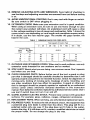
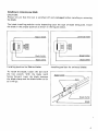
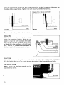
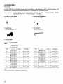
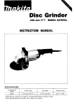
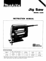
Jig Saw
MODEL 4320
INSTRUCTION MANUAL
DOUBLE
INSULA1'ION
SPECIFICAT IONS
Length of
stroke
Max. cutting capacities
Steel
Overall
length
0 - 3,200
174 mm
16-718")
I
Net
weight
I
I
18 mm
(1 1/16',)
Strokes
per minute
50 mm
6 mm
12")
I 1 14")
1.3 k g
12.9 Ibs)
IMPORTANT
SAFETY INSTRUCTIONS
(For All Tools)
WARNING: WHEN USING ELECTRIC TOOLS, BASIC SAFETY
PRECAUTIONS SHOULD ALWAYS BE FOLLOWED TO REDUCE
THE RISK OF FIRE, ELECTRIC SHOCK, AND PERSONAL
INJURY, INCLUDING THE FOLLOWING:
READ ALL INSTRUCTIONS.
1. KEEP WORK AREA CLEAN. Cluttered areas and benches invite injuries.
2. CONSIDER WORK AREA ENVIRONMENT. Don't use power tools in damp
or wet locations. Keep work area well lit. Don't expose power tools t o rain.
Don't use tool in presence of flammable liquids or gases.
3. KEEP CHILDREN AWAY. All visitors should be kept away from work area.
Don't let visitors contact tool or extension cord.
4.STORE IDLE TOOLS. When not in use, tools should be stored in dry, and high
or locked-up place - out of reach of children.
5. DON'T FORCE TOOL. It will do the job better and safer at the rate for which
it was intended.
6. USE RIGHT TOOL. Don't force small tool or attachment t o do the job of a
heavy-duty tool. Don't use tool for purpose not intended; for example, don't
use circular saw for cutting tree limbs or logs.
7 . DRESS PROPERLY. Don't wear loose clothing or jewelry. They can be caught
in moving parts. Rubber gloves and non-skid footwear are recommended
when working outdoors. Wear protective hair covering t o contain long hair.
8. USE SAFETY GLASSES. Also use face or dust mask if cutting operation is
dusty.
9. DON'T ABUSE CORD. Never carry tool by cord or yank it to disconnect from
receptacle. Keep cord from heat, oil, and sharp edges.
IO. SECURE WORK. Use clamps or a vise t o hold work. It's safer than using
your hand and it frees both hands t o operate tool.
11. DON'T OVERREACH. Keep proper footing and balance at all times.
12. MAINTAIN TOOLS WITH CARE. Keep tools sharp and clean for better and
safer performance. Follow instructions for lubricating and changing accessories. Inspect tool cords periodically and if damaged, have repaired by authorized service facility. Inspect extension cords periodically and replace if
damaged. Keep handles dry, clean, and free from oil and grease.
13. DISCONNECT TOOLS. When not in use, before servicing, and when changing accessories, such as blades, bits, cutters.
2
14. REMOVE ADJUSTING KEYS AND WRENCHES. Form habit of checking t o
see that keys and adjusting wrenches are removed from tool before turning
it on.
15. AVOID UNINTENTIONAL STARTING. Don’t carry tool with finger on switch.
Be sure switch is OFF when plugging in.
16. EXTENSION CORDS. Make sure your extension cord is in good condition.
When using an extension cord, be sure t o use one heavy enough t o carry
the current your product will draw. An undersized cord will cause a drop
in line voltage resulting in loss of power and overheating. Table 1 shows the
correct size to use depending on cord length and nameplate ampere rating.
If in doubt, use the next heavier gage. The smaller the gage number, the
heavier the cord.
TABLE 1 MINIMUM GAGE FOR CORD SETS
Total Lenath of Cord in Feet
I
10
12
-
10
12
16
0 - 25
18
16
14
1
26 - 50
I
51
-
100
I
101 - 150
16
16
14
14
12
12
12
Not Recommended
17. OUTDOOR USE EXTENSION CORDS. When tool is used outdoors, use only
extension cords intended for use outdoors and so marked.
18. STAY ALERT. Watch what you are doing, use common sense. Don’t operate
tool when you are tired.
19. CHECK DAMAGED PARTS. Before further use of the tool, a guard or other
part that is damaged should be carefully checked t o determine that it will
operate properly and perform its intended function. Check for alignment of
moving parts, binding of moving parts, breakage of parts, mounting, and
any other conditions that may affect its operation. A guard or other part
that is damaged should be properly repaired or replaced by an authorized
service center unless otherwise indicated elsewhere in this instruction
manual. Have defective switches replaced by authorized service center. Don’t
use tool if switch does not turn it on and off.
20. GUARD AGAINST ELECTRIC SHOCK. Prevent body contact with grounded
surfaces. For example; pipes, radiators, ranges, refrigerator enclosures.
21. REPLACEMENT PARTS. When servicing, use only identical replacement parts.
22. POLARIZED PLUGS. To reduce the risk of electric shock, this equipment has
a polarized plug (one blade is wider than the other). This plug will fit in a
polarized outlet only one way. If the plug does not fit fully in the outlet,
reverse the plug. If it still does not fit, contact a qualified electrician to install
the proper outlet. Do not change the plug in any way.
3
VOLTAGE WARNING: Before connecting the tool t o a power source (receptacle,
outlet, etc.) be sure the voltage supplied is the same as that specified on the
nameplate of the tool. A power source with voltage greater than that specified
for the tool can result in SERIOUS INJURY t o the user - as well as damage t o
the tool. If in doubt, DO NOT PLUG IN THE TOOL. Using a power source with
voltage less than the nameplate rating is harmful t o the motor.
ADDITIONAL SAFETY RULES
1. Avoid cutting nails. Inspect for and remove all nails from the workpiece before
operation.
2. Don't cut hollow pipe.
3. Do not cut oversize workpiece.
4. Check for the proper clearance beneath the workpiece before cutting so that
the blade will not strike the floor, workbench, etc.
5. Hold the tool firmly.
6. Make sure the blade is not contacting the workpiece before the switch is
turned on.
7. Keep hands away from moving parts.
8. When cutting through walls, floors or wherever "live" electrical wires may
be encountered, DO NOT TOUCH ANY METAL PARTS OF THE TOOL!
Hold the tool only by the insulated grasping surfaces to prevent electric shock
if you cut through a "live" wire.
9. Do not leave the tool running. Operate the tool only when hand-held.
IO. Always switch off and wait for the blade t o come t o a complete stop before
removing the blade from the workpiece.
11. Do not touch the blade or the workpiece immediately after operation; they
may be extremely hot and could burn your skin.
SAVE THESE INSTRUCTIONS.
4
Installing or removing saw blade
CAUTION :
Always be sure that the tool is switched off and unplugged before installing or removing
the blade.
The blade installing position varies depending upon the type of blade being used. Install
the blade in the proper position as shown in the figures below.
Universal blade
I
Blade holder
Blade holder
Blade clamp
Installing position for Makita blades
Installing position for universal blades
To install the blade, loosen the bolt with
the hex wrench. With the blade teeth
facing forward, insert the blade between
the blade clamp and the blade holder as far
as it will go.
Blade
5
Keep the blade shank flush with the installing position so that it does not ride up on the
shoulder of the blade holder. Tighten the bolt securely with the hex wrench.
3lade shank rides; up on shoulder
I f blade holder.
I
I
I
I
I
I
I
L - J
Blade holder
Correct
I
-0 remove the
Blade
Nrong
Blade
blade, follow the installation procedures in reverse.
Using roller
With the hex wrench, loosen the bolt which
holds the base and retainer. Slide the retainer so that the roller contacts the blade,
then tighten the bolt. However, when using
a blade that does not have a straight back
(e.g., Nos. 6, 71, slide the retainer back so
that the roller will not contact the blade.
CAUTION :
Use a lubricant or cutting oil between the blade and roller when cutting iron or composition board, etc. Failure to do so will shorten the service life of your blade and roller.
Hex wrench storage
When not in use, the hex wrench can be
conveniently stored.
6
Switch action
Tool speed is increased by increasing pressure on the trigger. To start the tool, simply
pull the trigger. Release the trigger t o stop.
For continuous operation, pull the trigger
and then push in the lock button. To stop
the tool from the locked position, pull the
trigger fully, then release it.
Lock button
/
CAUTION :
Before plugging in the tool, always check to see that the trigger switch actuates properly
and returns to the "OFF" position when released.
Operation
Turn the tool on and wait until the blade
attains full speed. Then rest the base flat
on the workpiece and gently move the tool
forward along the previously marked cutting line. When cutting curves, advance the
tool very slowly.
I
I
CAUTION :
Failure to hold the tool base flush with the workpiece may cause blade breakage.
Bevel cutting
With the base tilted, you can make bevel
cuts a t any angle between 0" and 45" (left
or right).
7
Loosen the bolt on the back of the base
with the hex wrench and slide the base
slightly backwards. Tilt the base to the desired angle. The edge of the housing indicates the bevel angle. Then check the contact between the back edge of the blade
and the roller. Now tighten the bolt securely on the back of the base.
\
Roller
\
Edge of housing
Front flush cuts
Loosen the bolt on the back of the base
with the hex wrench, then slide the base
backwards: Check the contact between the
back edge of the blade and the roller, then
secure the bolt.
Plunge cutting
Starting a cut a t other than the edge of the
workpiece without first drilling a starting
hole requires a “plunge cut”. This can be
accomplished by tipping the tool forward
until the front end o f the base rests against
the workpiece. Switch the tool on and
lower the back end of the tool slowly,
gradually allowing the blade to saw through
the workpiece until the base is able to s i t
flat on the workpiece. You may then proceed forward with the cut in a normal
manner.
If using a drill for a starting hole, bore a hole over 12 mm (1/2”) in diameter. Then insert
the blade in it and proceed.
8
Using guide rule (Rip fence)
When cutting widths of under 150mm (6")
repeatedly, use of the guide rule will assure
fast, clean, straight cuts.
To attach the guide rule (rip fence), secure
the rule holder to the base with the screw
(do not tighten).
Insert the guide rule between the base and
the rule holder. Now tighten the screw
with the hex wrench.
Using circular guide
Use of the circular guide insures clean,
smooth cutting of circles (radius, under
200 mm; 7-7/8") and arcs.
I
Circular guide
-
9
To attach the circular guide, use the pin,
inserting it in the center hole (arrow) and
secure it with the threaded knob. Then
slide the base of the tool forwards. The
circular guide attaches to the base of the
tool in the same manner as the guide rule
(rip fence).
F i t pin into
the hole
b
Pin for
circular guide
Metal cutting
Always use a suitable coolant (cutting oil)
when cutting metal. Failure to do so will
cause significant blade wear.
The underside of the workpiece can be
greased instead of using a coolant.
10
MA I NTENANCE
CAUTION :
Always be sure that the tool i s switched off and unplugged before attempting to perform
inspection or maintenance.
To maintain product SAFETY and RELIABILITY, repairs, carbon brush inspection
and replacement, any other maintenance or adjustment should be performed by Makita
Authorized or Factory Service Centers, always using Makita replacement parts.
11
ACCESSOR I ES
CAUTION:
These accessories or attachments are recommended for use with your Makita tool specified in this
manual. The use of any other accessories or attachments might present a risk of injury t o persons. The
accessories or attachments should be used only in the proper and intended manner.
A n exception : Universal shank jig saw blades w i t h a thickness of 1 mm - 1.25 mm (1/32"- 3/64')
and a length of 58 mm - 82 mm (2-9/32"
- 3-7/32").
0
Guide rule (Rip fence)
Part No. 164113-2
0
Circular guide assembly
Part No. 123030-5
0
Rule holder
Part No. 343381 -2
0
Hex wrench
Part No. 783201 -2
0
Jig saw blade
+ Packed 1 0 each
Packed 5 each
Blade
type
No 1
No.
N
o.2
1
Part No'
1
792145-5
W 792144-7
**
E
792136-6
792135-8
NO.3
No
792139-0
** 792138-2
.~
..-
No 4
792142-11 I
W 792141-3
_- .. 707,47
No. 5
No
No
NO. 7
**
++
792133-2
792132-4
7921
32 4
* 792152-8
** 792151-0
+ 792272-8
** 792268-9
,
,
Teeth
per inch
1
Effectlve
cuttmg length
24
60 mm 12.318'1
No. 8
14
60"
No
12-3/8")
Teeth
per inch
Part No.
792273-6
792269-7
792327-9
~
792288-3
Effective
cutting length
8
60 mm 12-318")
8
60 m m 12-318"l
60 m m l2-3/8"1
No. 10
60"
12-3/8")
No. 16
24
42 mm 11-5/8"1
No 17
9
60 mm 12-318")
No 41
t+ 792396-0
12
60 mm 12-318")
14
60 mm (2.318")
No 42
++ 792395-2
15
6 0 m m (2-3/8")
9
I
9
I
lYLLl
** 792207-9 1
I
.
701114
1
I
(Note1
Refer to the n e x t page for "Application" of each blade.
12
Blade
type
I
I
I
I
Applications
Feature
Blade type
Wood and plywood
Plartlcr
-_
1 5 - 6 m m thick
llllti, - 114,,1
No 1
1
No
No
No.5
No
No
,
No
No,9
No
I
1
I
I
I
lo
No 1 6
No 17
No 4 ,
No 42
I
I
3 - 55 mm thick
Aluminum
Mild steel
- 6 mm thick
(3164,,
114.pl
1 - 3 mm thick
(3164,, - 118.,l
1
A'so Ideal f o r Sta'nleSs Iteel
For corrugated plasticsand
tough plastics
i
l -
2-1/8"1
3 - 55 m m thick
1118" - 2-118")
3 - 55 mm thick
1118" - 2 1/8'')
3 - 55 mm thick
(1/8" - 2 - 1 / 8 " )
-
1 5 - 6 m m th,!ck
( 1 1 1 6 ' - 1/4 1
3-55"
thick
(118" - 2-118")
3 - 55 mm thick
(118'' - 2-118")
2 -55mmthick
15/64" - 2-118")
2 - 55 m m thick
15/64" - 2 118")
4-55"
15/32''
thick
2.118")
4 - 55 mm thick
15/32" - 2-118")
4-55mmthick
(5132" - 2-118")
4 - 55 m m thick
(5132" - 2-118")
4
- 55 m m thick
15132" - 2-118")
4 - 55 mm thick
(5/32" - 2-118")
--
-
For fast finish work.
especially in plywood
3 - 55 mm thick
1118"- 2 118")
3 - 55 m m thick
-
-
Ideal for scroll c u t t i n g
2 -55mmthick
2 - 55 mm thick
(5164"
15/64''
1118''
-
-
-
2-118")
1118"
-
-
I
1
I
3-50"
th>ck
I1 1 8 ' - 2")
3
2 - 50 m m thick
(5164 - 2")
2 - 50 mm thick
(5164' - 2 " )
For hardwoods, th'ck m'id
3 - 6 mm thick
(1/8', - 114,,)
steel plateand tough
I
I 1
1
I
1
i
I I - 1 -
I
1 - 6 m m thick
13/64" - 114")
2
- 10 mm thick
15164" - 318")
1 - 3 mm thick
13164" - 118")
2 - 6 mm thick
6 / 6 4 ' ' - 114")
PlaStlCS
Also ideal for stainless steel
For tough plastics
Ideal for scroll cutting.
Ideal for scroll cuttlng
For tough plastics
--
2-118")
2-1/8")
3 - 30 m m thqck
(1/8"
1.118'')
For ordinary w t t l n g
1
2 - 10 m m thick
(5164" - 318")
5 0 m m thick
I118" - 2")
-
-
I
I -
2 - 6 m m thlck
(5/64" - 114")
-
I
I
For fast finish work
for
CUtt,ng
For tough plastics and
decorative veneer fln!shing
For decorative veneers
13
Oec.-07-'93
US
JIG SAW
Model 4320
Note: The switch and other part configurations
may differ from country to country.
14
MODEL 4320
E
'M
Dec.-07-'93
DESCRIPTION
L' LM
DESCRIPTION
US
-
__
~
1
2
3
4
5
6
7
10
11
12
13
14
15
16
3
1
1
1
1
1
1
1
1
1
2
1
1
1
Plane Bearing 4
Slider
18
Sleeve 4
Gear
20
21
22
23
24
25
26
27
28
29
30
31
Pin 6
Switch
Housing Set (With Item 281
Cord
Name Plate
Ball Beating 607LLB
Carbon Brush
Terminal Base Complete 55C
Field
ARMATURE ASSEMBLY
IWith Item 12 & 16 - 18)
1
1
1
1
1
1
Ball Bearing 608LLB
Holder
Hex Socket Head Bolt
1
1
Stop Ring E-2 3
1
1
1
7
1
1
Flat Washer 4
Hex Socket Head Bolt M4x14 (With Washer)
Housing Set [With Item 71
Pan Head Screw M4x25 (With Washer)
Protector
Label
19
M4xB
Base
3
PI"
Roller
Retainer
-
Note' The switch and other part specifications may differ from country to country
15
MAKITA LIMITED ONE YEAR WARRANTY
Warranty Policy
Every Makita tool is thoroughly inspected and tested before leaving the factory. It is warranted t o
be free of defects from workmanship and materials for the period of ONE YEAR from the date of
original purchase. Should any trouble develop during this one-year period, return the COMPLETE
tool, freight prepaid, t o one of Makita’s Factory or Authorized Service Centers. If inspection shows
the trouble is caused by defective workmanship or material, Makita will repair (or at our option,
replace) without charge.
This Warranty does not apply where:
e repairs have been made or attempted by others:
e repairs are required because of normal wear and tear:
The tool has been abused, misused or improperly maintained;
alterations have been made t o the tool.
’
IN NO EVENT SHALL MAKITA BE LIABLE FOR ANY INDIRECT, INCIDENTAL OR CONSEQUENTIAL DAMAGES FROM THE SALE OR USE OF THE PRODUCT. THIS DISCLAIMER
APPLIES BOTH DURING AND AFTER THE TERM OF THIS WARRANTY.
MAKITA DISCLAIMS LIABILITY FOR ANY IMPLIED WARRANTIES, INCLUDING IMPLIED
WARRANTIES O F “MERCHANTABILITY” AND “FITNESS FOR A SPECIFIC PURPOSE,”
AFTER THE ONE-YEAR TERM O F THIS WARRANTY.
This Warranty gives you specific legal rights, and you may also have other rights which vary from
state t o state. Some states do not allow the exclusion or limitation of incidental or consequential
damages, so the above limitation or exclusion may not apply to you. Some states d o not allow
limitation on how long an implied warranty lasts, so the above limitation may not apply to you.
Makita Corporation
3-11-8, Sumiyoshi-cho,
Anjo, Aichi 446 Japan
aa3690~064
PRINTED IN JAPAN
I995 - 4 - N