1
aFTZ
MODEL NUMBER 917.258552
®
OWNER'S MANUAL
• Assembly
• Operation
• Customer Responsibilities
• Service and Adjustments
o Repair Parts
_UTION,
Read
and follow
FOR CONSUMER
I'llll
IIII
all safety
ASSISTANCE
IIIIIIIIIIIIIII
II I
rules and
instructions
before
operating
HOT LINE, CALL THfS TOLL FREE NUMBER:
this equipment.
1-800-659-5917
IIIIIIIIII
WIIIII
Ii
IIIIIIIIIIIIIIIIIIIIIIIIIIIIIIIIIIIIIIII
IIIIIIIIII
IIIIII
Illllllll
IIIIIIIIII
IIIII
IIIIIIIIHII
SAFETY
Practices RULES
for Ride-On
Safe Operation
Mowers
u
IMPORTANT:
THIS CUTTING MACHINE _S CAPABLE OF AMPUTATING
HANDS AND FEET AND THROWING
OBJECTS.
FAILURE TO OBSERVE THE FOLLOWING SAFETY INSTRUCTIONS
COULD RESULT ANSERIOUS INJURY OR DEATH.
i.
•
•
•
•
•
•
•
•
•
•
•
•
•
•
•
GENERAL OPERATION
Read, understand, and fo!Iow all instructions in the manual
andon the machine before starting.
Only allow responsible adults, who are familiar with the
instructions, to operate the machine.
Clear the area of objects such as rocks, toys, wire, etc,,
which could be picked up and thrown by the blade.
Be surethe area is clear of other people before mowing. Stop
machine if anyone enters the area.
Never carry passengers.
Do not mow in reverse unless absolutely necessary, Always
look down and behind before and while backing.
Be aware of the mower discharge direction and do not point
it at anyone. Do not operate the mower without either the
entire grass catcher or the guard in place,
Slow down before turning.
Never leave a running machine unattended, Always turn off
blades, set parking brake, stop engine, and remove keys
before dismounting.
Turn off blades when not mowing.
Stop engine before removing grass catcher or unclogging
chute.
Mow only in daylight or good artificial light.
Do not operate the machine while under the influence of
alcohol or drugs.
Watch for traffic when operating near or crossing roadways.
Use extra care when loading or unloading the machine into
a trailer or truck.
III.
CHILDREN
Tragic accidents can occur if the operator is not alert to the
presence
of children.
Children are often attracted to the
machine and the mowing activity.
Never assume that
children wilt remain where you last saw them.
•
Keep children out of the mowing area and under the watchful
care of another responsible adutt,
•
Be alert and turn machine off if children enter the area.
•
Before and when backing, look behind and down for small
children.
•
Never carry children, They may fall off and be seriously
injured or interfere with safe machine operation.
Never allow children to operate the machine.
Use extra care when approaching blind corners, shrubs,
trees, or other objects that may obscure vision.
•
•
IV. SERVICE
•
Use extra care in handling gasoline and other fuels. They are
flammable and vapors are explosive,
Use only an approved container,
Never remove gas cap or add fuel with the engine
running. Allow engine to cool before refueling. Do not
smoke.
Never refuel the machine indoors.
Never store the machine or fuel container inside where
there is an open flame, such as a water heater
Never run a machine inside a closed area,
•
•
II.
Keep nuts and bolts, especially blade attachment bolts, tight
and keep equipment in good condition.
Never tamper with safety devices.
Check their proper
operation regularly.
Keep machine free of grass, leaves, or other debris build, up.
Clean oil or fuel spillage. AIiow machine to coot before
storing,
Stop and inspect the equipment if you strike an object.
Repair, if necessary, before restarting.
Never make adjustments or repairs with the engine running.
Grass catcher components are subject to wear, damage, and
deterioration, which could expose moving parts or altow
objects to be thrown. Frequently check components and
replace with manufacturer's recommended parts, when necessary,
Mower bfades are sharp and can cut. Wrap the blade(s) or
wear gloves, and use extra caution when servicing them.
Check brake operation frequently.
Adjust and service as
required,
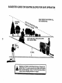
SLOPE OPERATION
Slopes are a major factor related to loss-of-control
and
tipover accidents, which can result in severe injury or death,
All slopes require extra caution.
If you cannot back up the
slope or if you feel uneasyon
it, do not mow it.
DO:
•
Mow up and down slopes, not across.
•
Remove obstacles such as rocks, tree limbs, etc.
•
Watch for holes, ruts, or bumps.
Uneven terrain could
overturn the machine. Tall grass can hide obstacles.
•
Use stow speed. Choose a low gear so that you will not have
to stop or shift while on the slope.
•
Fofiow the manufacturer's
recommendations
for wheel
weights or counterweights to improve stability.
•
Use extra care with grass catchers or other attachments.
These can change the stability of the machine.
•
Keep all movement on the slopes slow and gradual. Do not
make sudden changes in speed or direction.
•
Avoid starting or stopping on a slope. If tires lose traction,
disengage the blades and proceed slOwly straight down the
slope.
•
•
•
•
•
•
•
Hll
A
,IIIIIIHll
i ill
portant
safety precautions.
It means
Look for this BECOME
CAUTION!!!
symbol ALERT!!!
to point out
YOUR
imSAFETY IS INVOLVED.
Itl
DO NOT:
•
Do not turn on slopes unless necessary, and then, turn slowly
and gradually downhill, if possible.
•
Do not mow near drop-offs, ditches, or embankments. The
mower could suddenly turn over if a wheel is over the edge
of a cliffor ditch, or if an edge caves in.
°
Do not mow on wet grass. Reduced traction could cause
sliding,
•
Do not tryto stabilize the machine by putting your foot on the
ground.
•
Do not use grass catcher on steep slopes.
CAUTION:
A
l
Always disconnect
I tHlIHLtl!tt
L tt
spark plug
spark plug in order to prevent accidental
wire and place wirewhere it cannot contact
starting when setting up, transporting,
adjusting or making repairs.
iiiiiiiiii
i iiiijllll
i
ill
ii
i
iii
i
i
A WARNING
The engine exhaust from this product contains chemicals known to the State of California to cause cancer, birth defects, or other
reproductive
harm.
I I J IJIIIIIII
II1[
II
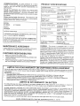
PRODUCT SPECUFltCATBONS
CONGRATULATIONS
on your purchase of a sears
Tractor. }t has been designed, engineered and manufactured to give you the best possible dependability and
performance_
Should you experience any probtem you cannot easily
remedy, please contact your nearest Sears Authorized
Service CentertDepartment.
We have competent, welttrained technicians and the proper tools to service o r repair
this tractor.
Please read and retain this manual. The instructions wifl
enable you to assemble and maintain your tractor properly.
Always observe the "SAFETY RULES".
MODEL
NUMBER
917.256552
SERIAL
NUMBER
DATE OF PURCHASE
THE MODELAND SERIAL NUMBERS WILL BE FOUND
ON A PLATE UNDER THE SEAT,
YOU SHOULD RECORD BOTH SERIAL NUMBER AND
DATE OF PURCHASE AND KEEP IN A SAFE PLACE
FOR FUTURE REFERENCE.
MAINTENANCE
CUSTOMER
=
•
is available on this prodstore for details.
RESPONSiBILITiES
Read and observe the safety rules.
Follow a regular schedule in maintaining, caring for and
using your tractor.
Follow the instructions
under"Customer
Responsibilities" and "Storage" sections of this owner's manual
LIMITED TWO YEAR WARRANTY
15.0
GASOLtNE CAPACITY
1.25 GALLONS
OiL TYPE (API-SF/SGiSH):
SAE 10W30 (above 32'_F)
SAE 5W-30 (below 32F)
O}L CAPACITY:
Wi FILTER:
WiO FILTER:
SPARK PLUG;
(GAP: .040")
CHAMPION
VALVE CLEARANCE:
NOT ADJUSTABLE
GROUND SPEED (MPH):
FORWARD:
REVERSE:
TIRE PRESSURE:
FRONT:
REAR:
CHARGING
3 AMPS BATTERY
5 AMPS HEADLIGHTS
SYSTEM:
4.0 PINTS
3.5 PINTS
RC12YC
0 - 5.5
0-2,4
14 PSI
10 PSi
BATTERY:
AMPiHR:
MIN, CCA:
CASE SIZE:
30
240
U1R
BLADE BOLT TORQUE!
AND TYPE:
30-35 FT. LBS.
UNLEADED REGULAR
WARNING:
This tractor is equipped with an internal
combustion engine and should not be used on or near any
unimproved forest-covered, brush-covered or grass-cow
ered land unless the engine's exhaust system is equipped
with a spark arrester meeting applicable tocal or state laws
(if any). If a spark arrester is used, it should be maintained
in effective working order by the operator.
In the state of California the above is required by law
(Section 4442 of the California Public Resources Code).
Other states may have similar laws. Federal laws apply on
federal lands, A spark arrester for the muffler is available
through your nearest Sears Authorized Service Center/
Department (See REPAIR PARTS section of this manual).
AGREEMENT
A Sears Maintenance
Agreement
uct. Contact your nearest Sears
HORSEPOWER:
ON CRAFTSMAN
RIDING EQUIPMENT
For two (2) years from the date of purchase, ff this Craftsman Riding Equipment is mair_tained, _ubricated and tuned up according
to the instructions in the owner's manual, Sears will repair or replace, free of charge, any parts found to be defective in material or
workmanship.
This Warranty does not cover:
=
Expendable items which become worn during normal use, such as blades, spark plugs, air cleaners, belts, etc_
o
Tire replacement or repair caused by punctures from outside objects, such as nails, thorns, stumps, or glass.
•
Repairs necessary because of operator abuse, negligence, improper storage or accident or the failure to maintain the
equipment according to the instructions contained in the owner's manual.
o
Riding equipment used for commercial or rental purposes.
LIMITED 90 DAY WARRANTY
ON BATTERY
For ninety (90) days from date of purchase, if any battery included with this dding equipment proves defective in materiai or
workmanship and our testing determines the battery will not hold a charge, Sears will replace the battery at no charge.
IN-HOME WARRANTY SERVICE ON YOUR CRAFTSMAN RIDING EQUIPMENT IS AVAILABLE AT NO-CHARGE FOR 30
DAYS FROM THE DATE OF PURCHASE. PLEASE CONTACT YOUR NEAREST SERVICE CENTER. AFTER 30 DAYS FROM
THE DATE OF PURCHASE, WARRANTY SERVICE IS AVAILABLE BY TAKING YOUR CRAFTSMAN RIDING EOUIPMENT TO
YOUR NEAREST SEARS SERVICE CENTER. (IN-ROME WARRANTY SERVICE WILL STILL BE AVAILABLE AFTER 30 DAYS
PROM THE DATE OF PURCHASE BUT A STANDARD TRIP CHARGE WILL APPLY.) THtS WARRANTY APPLIES ONLY
WHILE THIS PRODUCT IS IN THE UNITED STATES,
THis Warranty gives you specific legal rights, and you may also have other rights which may vary from state to state.
SEARS,
ROEBUCK
AND CO., D/817 WA, HOFFMAN
3
ESTATES,
IL 60179
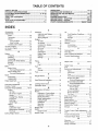
TABLE OF CONTENTS
SAFETY RULES ............................................................
2
PRODUCT SPECIFICATIONS ...................................... 3
CUSTOMER RESPONSIBILITIES
..................... 3, 16-19
WARRANTY ..................................................................
3
TABLE OF CONTENTS ................................................
4
INDEX ............................................................................
4
TRACTOR ACCESSORIES ..........................................
5
ASSEMBLY ................................................................
7-9
OPERATION ...........................................................
10-15
MAINTENANCE SCHEDULE ......................................
16
SERVICE AND ADJUSTMENTS ............................ 20-25
STORAGE ...................................................................
26
TROUBLESHOOTING ............................................
27-28
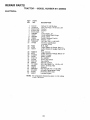
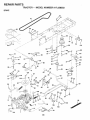
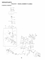
REPAIR PARTS - TRACTOR ................................. 30-47
REPAIR PARTS - ENGINE .................................... 48-53
PARTS ORDERING/SERVICE .................. BACK PAGE
INDEX
A
Accessories ............................................
Adjustments:
Brake ...........................................
Carburetor ...................................
Mower:
Front-To-Back ........................
Side-To-Side ..........................
Throttfe Contret Cable .................
Air Filter, Engine .................................
Air Screen, Engine .............................
Assembly ...........................................
B
5
22
25
21
21
24
18
18
7-9
Battery:
Charging .................................... 7-8
Cleaning ......................................
17
Connecting ................................ 7-8
Starting with Weak Battery .......... 23
Storage .......................................
28
Terminals ....................................
17
Belts:
Motion Drive
Removal/Replacement
........... 22
Mower Blade Drive
Removal/Replacement ........... 22
Blade:
Sharpening ..................................
17
Replacement ....... :....................... 17
Brake Adjustment ............................... 22
C
Carburetor Adjustment ....................... 25
Controls, Tractor ...............................
11
Customer ResDonsibifities ............. 16-19
Engine:
Air Filter ...................................
18
Air Screen. Engine .................. 19
Battery .....................................
17
Cooling Fins, Engine ............... 19
Engine Oil ...............................
19
Fuel Filter ................................
19
Spark Plugs ............................. 19
Tractor:
Blades .....................................
17
Lubrication Chart ..................... 16
Maintenance Schedule ........... 16
Tire Care ......................... 8,17,23
Cutting Height, Mower ........................
12
E
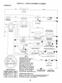
Electrical:
Interlocks and Relays ..................
Schematic ...................................
Wiring Diagram ...........................
Engine:
Air Filter .......................................
Air Screen ...................................
O
Oil:
24
29
30
18
19
Cooling Fins. Engine ................... I9
Oil Change ................................
!8
Oil Leve ..................................
13,i8
Oil Type .......................................
18
3reparation ...............................
I3
Repair Parts ........................... 48-53
Starting .......................................
t4
Storage .......................................
26
F
=ilters:
Air ................................................
t8
Fuel ...........................................
19
Fuel:
Type ............................................
13
Storage .......................................
26
--use ...................................................
24
G
Gauge Wheels .....................................
8
H
Hood Removalitnstaltation ................. 24
L
Leveling Mower Deck ......................... 21
Lubrication Chart ................................ 16
M
Maintenance Schedu{e ...................... !8
Mower:
Adjustment. Front-to-Back .......... 21
Adjustment. Side-to-Side ............ 21
Blade Sharpening ....................... 17
Blade Replacement ..................... t 7
Cutting Height ............................. 12
Installation ................................... 20
Ope ration .................................... 13
Removal ......................................
20
Mowing Tips .......................................
15
Muffler ................................................
19
Spark Arrester .......................... 3,40
Mulcher Plate .......................................
9
Cold Weather Conditions ....... 13,18
Engine .........................................
18
Storage .......................................
26
Ope ratio n ......................................
10-15
Operating Mower ................................ I3
Options:
Accessories ...................................
5
Spark Arrester .......................... 3,40
P
Parking Brake ................................ 11_12
Parts Bag .............................................
6
Parts, Replacement/Repair
........... 30-47
Product Specifications ........................... 3
R
Repair Parts ..................................
30-47
S
Safety Rules .........................................
2
Seat ......................................................
8
Service and Adjustments .............. 20-25
Brake ...........................................
22
Carburetor ...................................
25
Fuse ............................................
24
Hood Removal/installation
.......... 24
Motion Drive Belt
Removal/Replacement
........... 22
Mower Blade Drive Belt
RemovaflRepfacement
........... 22
Mower Adjustment:
Front-to-Back ......................... 21
Side-to-Side ........................... 21
Mower Installation ....................... 20
Mower Removal .......................... 20
Tire Sate ............................. 8,17,23
Slope Guide Sheet ............................. 55
Spark Plugs ........................................
19
Specifications .......................................
3
Starting the Engine ....................... 13-14
Steering Wheel ................................ 7,23
Stopping the Tractor ........................... 12
Storage ...............................................
26
T
Throttle Control Cable Adjustment ..... 24
Tires ...........................................
8,17,23
Trouble Shooting Chart .................. 27-28
Transaxte Repair Parts .................
W
46-47
Warranty ...............................................
Wiring Diagram ..................................
Wiring Schematic ...............................
3
30
29
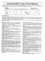
ACCESSORIES
AN
ATTACH
NTS
These accessories and attachments were available through most Sears retail outtets arid service r:er_ters when the tractor was purchased.
MoSt Sears stores can order these items for you when you provide the modet number of your tractor.
ENGINE
SPARK PLUG
GAS CAN
FUEL STABILIZER
AIR FILTER
]
PERFORMANCE
Sears offers a wide variety of attachments that fit your trhctor.
you. This list was current at the time of publication; however,
may be made in these attachments, or some may no longer
accessories
and attachments
that are available for your
Most of these attachments
attaching and detaching.
Many of these are iisted beiow with brief explanations of how they can help
it may change in future years - more attachments may be added, changes
be available or fit your model. Contact your nearest Sears store for the
tractor,
do not require additional hitches or conversion kits (those that do are indicated) and are designed for easy
AERATOR promotes deep root growth for a healthy tawn. Tapered 2.5qnch steel spikes mounted on 10-inch diameter discs
puncture holes in soil at close intervals to let moisture soak in.
Steel weight tray for increased penetration.
BAGGER lets you collect
grass clippings and leaves for a
healthier, heater looking lawn. Two Permanex containers hold
30-gallon plastic bags.
BUMPER protects front end of tractor from damage.
CARTS make hauling easy. Variety of sizes available, plus
accessories such as side panel kits, tool caddy, cart cover,
protective mat and deity.
CORING AERATOR takes smal_ plugs out of soii to allow moisture and nutrients to reach grass roots. 36-inch swath. 24
hardened steel coring tips. t50 lb. capacity weight tray.
EASY OIL DRAIN VALVE makes oii changes easier, faster.
FRONT NOSE ROLLER canters in front of mower deck to reduce
chances of "scalping" on uneven terrain.
GANG HITCH lets you tow 2 or 3 pulFbehind attachments at once,
such as sweepers, dethatchers, aerators (not for use with rollers,
carts or other heavy attachments).
GAUGE WHEELS on both sides of the mower deck reduce
chances of "scafping" on uneven terrain. For mower decks not so
equipped.
MULCH RAKF-./DETHATCHER loosens soil and flips thatch and
matted [eaves to lawn surface for easy pickup. Twenty spring tine
teeth. Usefulto prepare bare areasforseeding.
Available for front
or rear mounting.
HIGH PERFORMANCE
REEL-ACTION
SPRING TINE DETHATOHER covers 364rich wide path and
tosses thatch into large hopper, Mounts behind tractor.
MULCHING CLOSE-OUT PLATE KIT, once installed, lets you
mutch, discharge or bag clippings (bagger optional) without
changing blades. For models not equipped as 3-in-1 Convertible
mowers.
See "MOWER" in the Repair Parts section of this
manual.
RAMP TOPS AND FEET let you load and unload tractor from a
pickup truck. Use with 2 x 8 or 2 x 10 lumber.
ROLLER for smoother lawn surface,
36-inch wide, 18-inch
diameter water-tight drum holds upto 390 lbs. of weight. Rounded
edges prevent harm to tuff. Adjustable scraper automatically
cleans drum.
SNOW BLADE for snow removal only. 14qnch high, 48-inch wide
' blade clears 42-inch path when angled left or right. Raises, lowers
with side fever, Adjustable skids; reptaceabie_ reversible scraper
bar. (Use with tire chains and wheel weights and/or rear drawbar
weight,)
SNOWTHROWER has 4C-inch swath. Drum-type auger handles
powdery and wet/heavy snow. Mounts easily with simple pin
arrangement. Discharge chute adjusts from tractor seat. 6-inch
diameter spout discharges snow 10 to 50 feet. Lift controlled at
tractor seat. (Use with chains and wheel weights and/or rear
drawbar weight.)
SPRAYERS use 12-volt DC electric motor that connects to the
tractor battery or other 12-volt source.
Includes booms for
automatic spraying and hand held wand for spot spraying, Wand
has adjustable spray pattern. For applying herbicides, insecti_
cides, fungicides and liquid fertilizers.
SPREADER/SEEDERS
make seeding, fertilizing, and weed kilting easy. Broadcast spreaders are also useful for granular deicers and sand.
SWEEPERS let you collect grass clippings and leaves.
TILLER has 5 hp engine and 36-inch swath tOprepare seed beds,
cultivate and compost garden residue. Tiller has its own built-in
lift and depth control system and does NOT require a sleeve hitch.
Fits any !awn, yard or garden tractor. Simply hook up to the tractor
drawbar and go!
Optional
accessormes
convert unit for
dethatching, aerating, hilling...without tools.
TIRE CHAINS are heavy duty; closely spaced extra-large cross
links give smooth ride, outstanding traction.
TRACTOR CAB has heavy duty vinyl fabricover tubular steel
frame, ABS plastic top; clear plastic windshield offers 360 degree
visibility. Hinged metal doors with catch. Keeps operator warm
and dry. Remove vinyl sides and windshields for use as sun
protector in summer. Optional accessories
include:
tinted/
tempered solid safety glass windshield with hand operated wiper;
!2-volt amber caution Iight for mounting on cab top.
VACS for powerful collection of heavy grass c lJppings and leaves..
Optional wend attachment to pick up debris in hard-to-reach
places. VAC/CHIPPER includes a chipper-shredder.
WEIGHT BRACKET for drawbar for snow removal applications.
Uses (1) 55 lb. weight,
WHEEL WEIGHTS for rear wheels provide needed traction for
snow removal or dozing heavy materials.
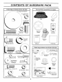
CONTENTS
Parts Bag
contents
shown
OF HARDWARE
ful
size
PACK
Parts packed
separately
in carton
(1) Large Flat Washer
"\\\X
t(1) Lockwasher
Seat
(1) Locknut
Mulcher
Plate
Steering
Wheel
5/16-18
Video
Cassette
x !-I/4
ill
I
(1) Lock
Washer
1/2
Steering
Boot
(1) Shoulder
Bolt 5/16-18
_,
Manual
Parts
Bag
H
Parts bag contents
(1) Hex Bolt
1/2-13 x 1
@(2)
._ashers
v
_,_,../
/
(2) Shoulder
Bolts
//'___/
_)/_!2
Gau ge
--._._si _)eels
@
(2) Centerlock Nuts
Extension
Shaft
Nuts
(2) Weld
#10 _
L_._
16 Gauge
(2) Hex Bolts 1/4-20 x 3/4
full size
(2) Screws
#10 x 5/8
#10
_)(2) Washers
3/t6x3/4x
not shown
(2) Washers 3/8
x 7/8 x 14 Gauge
(1) Wasf"
17/32 x
x 12 Gauge
Lock
__
I
teering
_J
Steering Wheel
Adapter
@
_,Steering
Wheel
Insert
(2) Keys
(2) Hex Nuts 1/4-20
_k
Assembtys
(2) Washers
9/32 x 5/8 x 16 Gauge
(2) Lock Washers
Slope Sheet
1/4
6
ASS
111111 ii
LY
............
Your new tractor has been assembled at the factory with exception of those pa_s teft unassembled for shipping purposes.
To ensure safe and proper operation of your tractor a{t parts and hardware you assemble must be tightened secureiy Use
the correct tools as necessary to insure proper tightness.
TOOLS
REQUIRED
FOR ASSEMBLY
A socket wrench set will make assembly easier, Standard
wrench sizes are listed.
(1) 9/16" wrench
Utility knife
(2) 7/!6 '_wrenches
Phi!lips Screwdriver
(2) 1/2" wrenches
"Tire pressure gauge
(1) 3/4" Socket w/drive rachet
When right or Ieft hand is mentioned in this manual, it
means when you are in the operating position (seated
behind the steering wheel).
TO REMOVE TRACTOR
UNPACK
o
,
•
FROM CARTON
STEERING
BOOT"
STEER|NG
WHEEL
CARTON
Remove aN accessible loose parts and pads cartons
from carton (See page 6).
Cut, from top to bottom, along lines on all four corners
of carton, and Iay panets flat.
Check for any additional loose parts or cartons and
remove.
BEFORE ROLL|NG TRACTOR
EXTENSION
SHAFT
OFF SKID
ADAPTER
ATTACH
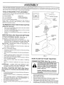
ASSEMBLE
STEERING
WHEEL
(See Fig. 1)
5116 HEX
EXTENS!ON SHAFT AND BOOT
,
Slide extension shaft onto lower steering shaft. Align
mounting holes in extension and lower shafts and
install 5/16 hex bolt and 10cknuL Tighten securely.
IMPORTANT; TIGHTEN BOLT AND NUT SECURELY TO
18-22 FT. LBS TORQUE.
5/16
LOCKNUT
•
Place tabs of steering boot over tab slots in dash and
push down to secure.
iNSTALL STEERING WHEEL
=
•
•
•
Position front wheels of the tractor so they are pointing
straight forward.
Slide steering wheel adapter onto steering shaft extension.
Position steering wheel so cross bars are horizontal
0eft to right) and slide onto adapter.
Assemble large flat washer, 3/8 lock washer, 3/8 hex
bolt and tighten securely,
Snap steering wheel insert into center of steering
wheel.
t
%
HOW TO SET UP YOUR TRACTOR
CONNECT
,
.
,
BATTERY
,,
, ii,,i,ilUlUll
(See Figs.
,
2 and 3)
ul
iii
i
CAUTION: Do not short battery terminals by allowing a wrench or any other
object to contact both terminals at the
same time. Before connecting battery,
remove metal bracelets,
wristwatch
bands, rings, etc.
TO ROLL TRACTOR
OFF SKID {See Operation section for location and function
of controis)
,
/
FIG. 1
Remove protective materials from tractor hood and
grill.
IMPORTANT:
CHECK FOR AND REMOVE ANY
STAPLES IN SKID THAT MAY PUNCTURE TIRES
WHERE TRACTOR IS TO ROLL OFF SKID.
Press lift lever plunger and raise attachment lift lever to
its highest position.
Release parking brake by depressing dutch/brake
pedal.
Place freewheel control in freewheeling position to
disengage transmission (See 'TO TRANSPORT" in
the Operation section of this manual).
Roll tractor backwards off skid.
Remove banding holding discharge guard up against
tractor,
!
t
•
,
.
/
/
f
Positive termina! must be connected
first to prevent sparking from accidental
grounding•
•
Remove carboard packing from seat pan and lift seat
pan to raised position.
Open battery box door.
Be sure battery drain tube. is attached to battery box.
Remove terminal protective caps and discard.
If this battery is put into service after month and year
indicated on label (label located between terminals)
charge battery for minimum of one hour at 6-10 amps,
ASSEMBLY
=
First con nect RED battery cable to positive (+) terminal
with hex bott, ftat washer, _ockwasher and hex nut as
shown. Tighten securely,
o
Conr_ect BLACK grounding cable to negative (-) terminal with remaining hex bolt, flat washer, lock waslqer
and hex nut. Tighten secureiy.
*
Close batterv box door.
Open battery box door for:
*
inspection for secure connections (to tighten hard-
SEAT
SEAT PAN
ware),
-
Inspection for corrosion.
Testing battery,
Jumping (if required),
Periodic charging.
LARGE FLAT
WASHER
ADJUSTMENT
BOLT
3K WASHER
FIG, 4
D|SCARD
TERMINAL
PROTECTIVE
CAPS
HEX
NUT
LOCK
WASHER
CHECK TIRE
PRESSURE
The tires on your tractor were overinfiated
shtpping purposes. Correct tire pressure
best cutting performance,
•
Reduce t}re pressure to PSI shown
SPECIFICATIONS" on page 3 of this
FLAT
WASHER
HEX
BOLT
CHECK
at the factory for
is important for
in "PRODUCT
manual
DECK LEVELNESS
For best cutting resufts, mower housing should be property
leveted. See "TO LEVEL MOWER HOUSING" in the
Service and Adjustments section of this manual.
POSrFIVE
(RED) CABLE
NEGATIVE
(BLACK) CABLE
I
[
J
CHECK
BELTS
FIG. 2
FOR
PROPER
OF
ALL
See the figures that are shown for replacing motion and
mower blade drive belts in the Service and Adjustments
section of this manual. Verify that the belts are routed
correctly.
SEAT
PAN
CHECK
BRAKE
SYSTEM
After you learn how to operate your tractor, check to see
that the brake is properly adjusted. See "TO ADJUST
BRAKE" in the Service and Adjustments section of this
manual.
BATTERY
BOX
DOOR
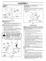
ASSEMBLE
GAUGE
DECK (See Fig, 5)
WHEELS
TO
MOWER
The gauge wheeis are designed to keep the mower deck in
proper position when operating mower, Be sure they are
properly adjusted to ensure optimum mower performance.
FIG. 3
INSTALL
POSITION
Assembfe gauge wheels with tractor on a flat level
surface.
SEAT (See Fig. 4)
Adjust seat before tightening adjustment belt.
*
Remove cardboard packing on seat pan,
.
Place seat on seat pan and assemble shoutder bolt,
.
AssembleadjustmentboR,
Iockwasherandfiatwasher
loosely, Do not tighten,
Tighten shoulder bolt securely,
.
Lower seat into operating position and sit on seat.
Slide seat until a comfortable position is reached which
allows you to press clutch/brake pedal all the way
down.
Get off seat without moving its adjusted position.
Raise seat and tighten adjustment bo!t securely.
Adjust mower to desired cutting height (See 'q'o ADJUST MOWER CUTTING HEIGHT" in the Operation
section of this manual),
8
•
With mower in desired height of cut position, gauge
wheels should be assembled so they are slightly off the
ground, Install gauge wheel in appropriate here with
shoulder bolt, 3/8 washer, and 3/8-I6 iocknut and
tighten securely,
,
Repeat for opposite side installing gauge wheel in
same adjustment hole.
ASSEMBLY
TO CONVERT TO BAGGING
D|SCHARG_NG
GAUGE WHEEL
MOUNTING
BRACKET
OR
Simply remove mulcher plate and store in a safe place.
Your mower is now rea.dy for discharging or installation of
optional grass catcher accessory.
3/8-16
LOCKNUT
FiG° 5
INSTALL MULCHER
(See Figs. 6 & 7)
•
LATCH
HOOKS
PLATE
FiG. 7
Install two latch hooks to mulcher plate using screw,
washer, lock washer, and weld nut as shown.
,/CHECKLIS
NOTE: Pre=assemb_e we_d nut to latch hook by inserting
weld nut from the top with hook pointing down.
.
Raise a.nd held deflector shield in upright position.
-
Place front of mulcher plate over front of mower deck
opening and slide into place, as shown.
Hook front latch into hole on front of mower deck.
•
BEFORE YOU OPERATE AND ENJOY YOUR NEW
TRACTOR, WE WISH TO ASSURE THAT YOU RECEIVE
THE BESTPERFORMANCEAND
SATISFACTION FROM
THIS QUALITY PRODUCT.
Tighten hardware securely.
=
T
PLEASE REVIEW THE FOLLOWING
Hook rear latch into hole on back of mower deck.
CHECKLIST:
¢"
All assembly instructions have been completed.
¢'
No remaining loose parts in carton.
V" Battery is proper'ty prepared and charged.
1 hour at 6 amps).
guard from mower. Raise and hold
guard
whenDoattaching
mulcher
plate
CAUTION:
not remove
discharge
and allow it to rest on plate while in
operation.
=
-
WELD NUT FROM THE TOP
WELD
NUT\ X
,/
Seat is adjusted comfortably and tightened securely.
¢
All tires are properly inflated. (For shipping purposes,
the tires were overinflated at the factory).
,/
Be sure mower deck is properly Ieveled side-to-side/
front-to-rear for best cutting results. (Tires must be
properly inflated for leveling).
v"
Check mower and drive belts. Be sure they are routed
properly around pulleys and inside at! belt keepers.
€'
Check wiring. See that all connections are still secure
and wires are properly clamped.
¢
Before driving tractor, be sure freewheel control is in
drive position.
HOOK POINTS DOWN
LOCK
WASHER
SCREW
WHILE LEARNING HOWTO USE YOUR TRACTOR, PAY
EXTRA A TTENTtON TO THE FOLLOWING IMPORTANT
ITEMS:
LATCH
LATCH
HOOK
LOCK
WASHER
WASHER
(Minimum
¢'
Engine oil is at proper level.
,/
Fuel tank is filled with fresh, clean, regular unleaded
gasoline;
Become familiar with all controls - their location and
function. Operate them before you start the engine.
WELD
NUT
,/
MULCHER
PLATE
FIG. 6
9
,/
Be sure brake system is in safe operating condition.
7
it is important to purge the transmission before operating your tractor for the first time. Follow proper starting
and transmission purging instructions (See'q'O START
ENGINE" and "PURGE TRANSMISSION" in the Operation section of this manual).
OPERATION
These
symbols
may appear
on your tractor or in literature supplied
with the prodLct
Learn and understand
their meaning.
i'
BATTERY
CAUTION OR
.WARNING
REVERSE
FORWARD
FAST
SLOW
ENGINE ON
ENGINE OFF
OIL PRESSURE
CLUTCH
LIGHTS ON
LIGHTS OFF
FUEL
CHOKE
MOWER HEIGHT
DIFFERENTIAL
LOCK
PARKING BRAKE
LOCKED
UNLOCKED
L
REVERSE
MOWER LIFT
NEUTRAL
ATTACHMENT
CLUTCH ENGAGED
HIGH
•
LOW
PARKING BRAKE
ATTACHMENT
CLUTCH DISENGAGED
HYDROSTATIC
DANGER, KEEP HANDS AND FEET AWAY
IGNITION
FREE WHEEL
(Hydro Models only)
t0
OPERATION
t
r,ll, i
,,
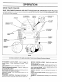
KNOW YOUR TRACTOR
READ THIS OWNER'S
MANUAL
AND SAFETY
RULES
BEFORE
OPERATING
YOUR
TRACTOR
Compare the illustrations with your tractor to familiarize yourself with the locations of various corttrots and adjustments,
this manual for future reference.
ATTACHMENT
CLUTCH LEVER
IGNmON
SWITCH
Save
LIGHT SWITCH
POSiTiON
LtFT LEVER
PLUNGER
THROTTLE/CHOKE
CONTROL
LIFT
LEVER
ATTACHMENT
CLUTCHfBRAKE
PEDAL
PARK{NG
BRAKE
HEIGHT
ADJUSTMENT
KNOB
MOTION
CONTROL
LEVER
FREEWHEEL
CONTROL
APPROX.
SPEED
3 MPH
2MPH
1MPH
FIG, 8
Our tractors conform to the safety standards of the American National Standards Institute.
.......
,,,,,,,,,,,,,,,
,
lViOTION CONTROL
direction of tractor.
ATTACHMENT CLUTCH LEVER: Used to engage the
mower blades, or other attachments mounted to your
tractor,
LIGHT SWITCH:
LiFT LEVER PLUNGER: Used to release attachment lift
lever when changing its position,
Used for starting and
CLUTCHtBRAKE PEDAL: Used for declutching and braking the tractor and starting the engine,
iGNiTION SWITCH:
engine.
PARKING BRAKE:
brake position.
HEIGHT ADJUSTMENT
cutting height.
Locks clutch/brake
Selects the speed and
ATTACHMENT LiFT LEVER: Used to raise and lower the
mower deck or other attachments mounted to your tractor,.
Turns the headlights on and off.
THROTTLE/CHOKE
CONTROL:
controlling engine speed.
LEVER:
pedal into the
FREEWHEEL CONTROL - Disengages transmission for
pushing or slowly towing the tractor with the engine off.
AMMETER"
(-).
11
Used for starting and stopping the
KNOB: Used to adjust the mower
indicates battery charging (+) or discharging
i
ii
iii
i
--IIII-
OPERATION
=,
,
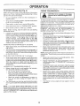
any tractor can result in foreign objects thrown into the eyes, which can
_ __esultinsevereeyedamage.
AIwayswearsafetyglassesoreyeshieidswhifeoperatingyour
_
tar ctor or performing any adjustments or repairs. We recommend a wide vision safety mask
over the spectacles or standard safety gtasseso
NOTE: Under certain conditions when tractor is standing
idle with the engine running, hot engine exhaust gases may
cause "browning" of grass. To eliminate this possibility,
always stop engine when stopping tractor on grass areas.
HOW TO USE YOUR TRACTOR
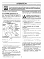
TO SET PARKING
BRAKE
Fig. 9)
(See
You r tractor isequipped With an operator presence sensing
switch. When engine is running, any attempt by the
operator _o leave the seat without first setting the parking
brake will shut off the engine,
_
_ion;
p_e__ve,
TO USE
THROTTLE
before leavtO empty
Depress clutch/brake pedal into full "BRAKE" position
and hold.
•
Place parking brake lever in "ENGAGE D" position and
release pressu re from clutch/brake pedal. Pedal should
remain in "BRAKE" position. Make sure parking brake
will hold tractor secure,
ATTACHMENT
THROTTLE/
"ENGAGED"
IGNITION
SWITCH
CHOKE
CONTROL
o
Operating engine at less than, fun throttle reduces the
battery charging rate.
,
Full throttle offers the best bagging and mower performance.
TO MOVE
POSiTiON
(See
PARKING BRAKE
"ENGAGED"
POSITION
"BRAKE"
POSiTiON
(See Fig. 9)
Always operate engine at full throttle,
CLUTCH LEVER
POSITION
CONTROL
FORWARD
AND
BACKWARD
Fig, 9)
The direction and speed of movement is controlled by the
motion control lever.
MOTIONCONTROL
=
Start tractor with motion control lever in neutral iN)
position.
•
Release parking brake and clutch/brake
pedal.
Slowly move motion control lever to desired position,
"DISENGAGED"
POSiTiON
CLUTCH/BRAKE PEDAL
"DRIVE"POSiTION
TO ADJUST
(See
HEIGHT ADJUSTMENT KNOB
MOWER
CUTTING
HEIGHT
Fig. 9)
The cutting height is controlled by turning the height adjustment knob in desired direction.
FiG. 9
Turn knob clockwise (f"_t) to raise cutting height.
STOPPING
(See Fig. 9)
Turn knob counterclockwise
height.
MOWER BLADES •
Move attachment clutch lever to "DISENGAGED"
sition.
Depress clutch/brake pedal into full "BRAKE" position.
Move motion control lever to neutral iN) position.
IMPORTANT:
THE MOTION CONTROL LEVER DOES
NOT RETURN TO NEUTRAL iN) POSITION WHEN THE
CLUTCH/BRAKE PEDAL IS DEPRESSED.
=
ENGINE o
Move throttle control to slow (_)
Never use choke to stop engine.
The average lawn should be cut to approximately 2-1/2
inches during the cool season and to over 3 inches
during hot months, For healthier and better looking
lawns, mow often and after moderate growth.
For best cutting performance, grass over 6 inches in
height should be mowed twice. Make the :first cut
relatively high; the second to desired height.
position.
NOTE: Failure to move throttle control to slow (,_m_)
position and at!owing engine to idle before stopping may
cause engine to "backfire".
Turn ignition key to "OFF" position and remove key.
Always remove key when leaving tractor to prevent
unauthorized use.
•
to lower cutting
The cutting height range is approximately t-1/2" to 4". The
heights are measured from the ground to the blade tip with
the engine not running. These heights are approximate
and may vary depending upon soil conditions, height of
grass and types of grass being mowed.
po-
GROUND DRIVE •
(}_)
12
OPERATION
TO OPERATE
MOWER
Raise attachmer_t lift to highest position with attachment lift control
(See Fig. 10)
Your tractor isequipped with an operator presence sensing
switch. Any attempt by the operator to leave the seat with
the engine running and the attachmer_t clutch engaged will
shut off the engine_
•
Select desired height of cut.
°
Lower mower with attachment lift control
Start mower blades by _n_t,,g
_ _,'_.
attachment clutch
control.
,
TO STOP MOWER BLADES - disengage attachment
clutch control.
*
Puli freewheel co[ltrol knob out and hold in position by
inserting retainer spring into forward hete of controt rod.
Do not push or tow tractor at more than two (2} MPH.
,
To reengage tr_r_smissien, reverse above procedure.
NOTE: To protect hood from damage when transporting
your tractor on a truck or a trailer, be sure hood is ciosed and
secured to tractor. Use an appropriate means of tying hood
to tractor (rope, cord, etc.).
CAUTION: Do not operate the mower
without either the entire grass catcher,
on mowers so equipped, or the .discharge guard in place.
=,1 uu,
i i
......
ATTACHMENT
CLUTCHLEVER
"ENGAGED"
POSmON
ATTACHMENT
LIFT LEVER
HUGH POSITION
POSiTiON
FtGo 11
• BEFORE
CHECK
•
°
-
D|SCHARGEi
GUARD
STARTWNG THE ENGINE
ENGENE OiL LEVEL
(See Fig, 16)
The engine in your tractor has been shipped, from the
factory, already fitted with summer weight oil.
Check engine oil with tractor on level ground
Unthread and remove el! fill cap/dipstick; wipe oil off.
Reinsert the dipstick into the tube and rest oil fill cap on
the tube. Do not thread the cap onto the tube. Remove
and read oil level. If necessary, add oil until "FULL"
mark on dipstick is reached. Do not overfill.
For cold weather operation you should change oil for
easier starting (See'OIL VISCOSt TY C HAR T" ' n the
Customer Responsibilities section of this manual).
Tochange engine oil, see the Customer Responsibilities section in this manual.
ADD GASOLINE
FiG. 10
TO OPERATE
•
Fill fue! tank. Use fresh, clean, regular unleaded
gasoline with a minimum of 87 octane, (Use of leaded
gasoline will increase carbon and lead oxide deposits
and reduce valve tile). Do not mix oil with gasoline.
Purchase fuel in quantities that can be used within 30
days to assure fuel freshness.
IMPORTANT: WHEN OPERATING IN TEMPERATURES
BELOW32_F(0°C), USE FRESH, CLEAN WINTER GRADE
GASOLINE TO HELP INSURE GOOD OOLD WEATHER
STARTING.
ON HILLS
eupQrdow,,hill
_I
Ill _ I
wPh_an
!5 ° and donot
drive across any slope,
I
Choose the slowest speed before starting up or down
Mils.
Avoid stopping or changing speed on hills.
*
If slowing is necessary, move throttle control lever to
slower position,
,
If stopping is absolutely necessary, push clutch/brake
pedal quickly to brake position and engage parking
brake.
= Move motion controt lever to neutral (N) position.
iMPORTANT:
THE MOTION CONTROL LEVER DOES
NOT RETURN TO NEUTRAL (N) POSITION WHEN THE
CLUTCH/BRAKE PEDAL IS DEPRESSED,
To restart movement, slowly release parking brake and
clutch/brake pedal
.
Slowly move motion control lever to slowest setting.
.
Make all turns slowly.
TO TRANSPORT
WARNING:
Experience indicates that alcohol blended
fuels (called gasohol or using ethanol or methanol) can
attract moisture which leads to separation and formation of
acids during storage. Acidic gas can damage the fue!
system of an engine while in storage_ To avoid engine
problems, the fuel system should be emptied before stor-.
age of 30 days or longer. Drain the gas tank, start the
engine and Jet it run untit the fue! lines and carburetor are
empty, Use fresh fue! next season. See Storage Instructions for additional information.
Never use engine or
carburetor cleaner products in the fuel tank or permanent
damage may occur.
(See Figs. 8 and 11)
When pushing or towing your tractor, be sure to disengage
transmission by p_acing freewheel controt in freewheeling
position. Free wheel control is located at the rear drawbar
of tractor.
t3
O ERATION
7ro START
ENGINE
(See Fig. 9)
PURGE TRANSMISSION
When starting the engine for the first time or if the engine
has run out of fuel, it will take extra cranking time to move
fuet from the tank to the engine.
,
Be sure freewheet cdntrol is in the transmission
gaged position.
em
[dote: Before starting, read the warm and cold starting
procedures below.
To ensure proper operation and performance, it is recommended that the transmission be purged before operating
tractor for the first time. This procedure will remove any
trapped air Jnside the transmission which may have developed during shipping of your tractol °.
IMPORTAN3"," SHOULD YOUR TRANSMISSION REQUIRE
REMOVAL FOR SERVICE OR REPLACEMENT,
1T
SHOULD BE PURGED AFTER REINSTALLATION
BEFORE
OPERATING THE TRACTOR.
o
"
Place tractor safely on level surface with engine off and
parking brake set.
*
Disengage transmission by placing freewheel control
in freewheeling position (See "TO TRANSPORT" in
this section of manual).
=
Sitting in the tractor seat, start engine. After theengine
is running, move throttle controt to stow (,_i_) position.
With motion control lever in neutral (N) position, slowly
disengage clutch/brake pedal.
.
Move motion control lever to rut! forward position and
hold for five (5) seconds. Move lever to full reverse
position and hold for five (5) seconds.
Repeat this
procedure three (3) times,
o
Sit on seat in operating position_ depress clutch/brake
pedal and set parking brake.
Place motion control lever in neutral (N) position.
o
Move attachment c_utch to "DISENGAGED"
o
Move throttle control to choke (i_,l) position.
position.
Insert key into ignition and turn key clockwise to"START"
position and release key as soon as engine starts. Do
not run starter continuously for more than fifteen seconds per minute, If the engine does not start after
several attempts, move throttle control to fast (,_)
position_ wait a few minutes and try again, tf engine still
does not start, move the throttle control back to the
choke (1\1)
position and retry.
WARM WEATHER STARTING (50 ° F and above)
When engine starts, move the throttle controlto the fast
(@) position_
•
The attachments and ground drive can now be used, if
the engine does not accept the load, restart the engine
and allow it to warm up for one minute using the choke
as described above.
COLD WEATHER
•
NOTE: During this procedure there will be no movement of
drive wheels. The air is being removed from hydraulic drive
system.
STARTING ( 50 ° F and below)
Move motion controt lever to neutral (N) position. Shutoff engine and set parking brake.
When engine starts, ailow engine to run with the throttle
control in the choke (fXI) position until the engine runs
roughly, then move throttle control to fast (,€_) position.
This may require an engine warrn-up period from
several seconds to several minutes, depending on the
temperature.
HYDROSTATIC
TRANSMISSION
Engage transmission by placing freewheel control in
driving position (See "TO TRANSPORT" in this section
of manua!).
WARM UP
Before driving the unit in cold weather, the transmission should be warmed up as follows:
• Be sure the tractor is on leVel ground.
. Place the motion control lever in neutral.
Release the parking brake and let the clutch/brake
slowly return to operating position.
• Allow one minute for transmission to warm up.
This can be done during the engine warm up
period.
The attachments canalso be used during the engine
warm-up period after the transmission has been warmed
up.
NOTE: If at a high altitude (above 3000 feet) or in cold
temperatures (below 32 F) the carburetor fuel mixture may
need to be adjusted for best engine performance. See "TO
ADJUST CARBURETOR" in the Service and Adjustments
section of this manual,
14
,
Sitting in the tractor seat, start engine. After the engine
is running, move throttle control to half (1/2) speed.
With motion control lever in neutral (N) position, slowly
disengage clutch/brake pedal.
,
Slowly move motion control lever forward, after'the
tractor moves approximately five (5) feet, slowly move
motion control lever to reverse position.
After the
tractor moves approximately five (5) feet return the
motion control iever to the neutral (N) position. Repeat
this procedure with the motion control lever three (3)
times.
,
Your tractor is now purged and now ready for normal
operation.
0
ERAT!ON
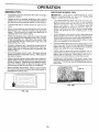
MOWING TiPS
MULCHING
-
Tire chains cannot be used when the mower housing is
attached to tractor.
iMPORTANT:
FOR BEST PERFORMANCE,
KEEP
MOWER HOUSING FREE OF BUILT-UP GRASS AND
TRASH. CLEAN AFTER EACH USE,
o
Mower should be properly teveled for best mow!_g
performance. See TO LEVEL MOWER HOUSING n
the Service and Adjustments section of this manual,
•
•
The left hand side of mower should be used for trimming,
•
Drive so that clippings are discharged onto the area
that has been cut. Have the cut area to the right of the
tractor. This wilt result in a more even distribution of
clippings and more uniform cutting.
When mowing large areas, staff by turning tO the right
so that clippings' will discharge away from shrubs,
fences, driveways, etc. After one or two rounds, mow
in the opposite direction making left hand turns until
finished (See Fig. 12A ),
The special mu_ching b)ade wiit recur the grass cIippings many times and reduce them in size so that as
they ta_ onto the _awnthey wi_fdisperse into the grass
and not be noticed. Also, the mulched grass will
bi0degrade quickly to provide nutrients for the lawn.
Always mulch with your highest engine (blade) speed
as this will provide the besl recurring action ol the
blades.
,
Avoid cutting your lawn when it is wet. Wet grass tends
to form clumps and intederes with the mulching action.
The best time to mow your lawn is the early afternoon.
At this time the grass has dried and the newly cut area
wi!t not be exposed to the direct sun.
•
For best results, adjustthe mower cutting height so that
the mower cuts off only the top one-third of the grass
blades (See Fig. 12B). For extremely heavy mulching,
reduce your width of cut and mow slowly.
s
Certain types of grass and grass conditions may require that an area be mulched a second time to compietefy hide the clippings. When doing a second cut,
mow across or perpendicular to the first cut path.
,
Change your cutting pattern from week to week. Mow
north to south one week the n chan ge to east to we st the
next week. This will help prevent matting and graining
of the lawn.
=
-
•
if grass is extremely tall, it should be mowed twice to
reduce load and possible fire hazard from dried clippings. Make first cut relatively high; the second to the
desired height.
Do not mow grass when it is wet. Wet grass will plug
mower and leave undesirable clumps. Allow grass to
dry before mowing.
-
Always operate engine at full throttle when mowing to
assure better mowing performance and proper discharge of material. Regulate ground speed by selecting a low enough gear to give the mower cutting
performance as welt as the quality of cut desired.
,
When operating attachments, select a ground speed
that will suit the terrain and give best performance of
the attachment being used.
MOW|NG
TIPS
MAX 1/3
f-
]
it
FIG. 12B
FIG. !2A
15
CUSTOMER
MAINTENANCE
RESPO
ILJTIES
SCHEDULE
FtLL IN DATES
AS YOU COMPLETE
REGULAR
SERVICE
SERVICE
Check
Brake Operation
Check
fil'e
Check
for Loose _-asteners
Pressure
Sharpen/Replace
Lubdcation
DATES
Mower
BIades
Chart
Check
Bet_ery Leve!iRecharge
Clean
Battery
apd Terminals
Cooling
Adjust
Blonde Belt(s)
Adjust
Motior_ Drive Belt(s) Tension
Check
Engine
Change
Tension
Oil Level
Engine
Oil
Clean Air Filter
Clean Air Screen
inspect
Muffler/Spark
Replace
Arrester
Oi_ Filter (If equipped)
Clean Engine
Cooling
Fins
Replace
Spark
Piug
Replace
Air Filter Paper Cadridge
Rep!ace
Fuel Filter
1 * Change more often when operat}ng under a heavy lead or in high ambient temperatures.
2 _ Sewice mo_e often when operating in di_y or dusty conditions.
3 - tt equipped wflh oft fitter, change oi_ ever7 50 ltoars.
4 - Replace btades more often when mowing in sandy soil
GENERAL
5 - If equipped with adjustable system.
8 - Not required if equipped with maintenance4ree
battery.
7 _ Tighten front a_le pivot bolt to 35 ft.dbs, maximum,
Do not overtighten,
RECOMMENDATIONS
LUBRJCATmON
The warranty on this tractor does not cover items that have
been subjected to operator abuse or negligence.
To
receive full value from the warranty, operator must maintain
tractor as instructed in this manual.
CHART
®
(_) SPINDLE ZERK --
®
Some adjustments wilt need to be made periodicaIfy to
properly maintain your tractor.
FROI_
BEARING
FRONT WHEEL ®
BEARING ZERK
ZERK
All adjustments in the Service and Adiustments section of
this manual should be checked at least once each season.
,
Once a year you should replace the spark plug, clean
or replace air filter, and check blades and belts for
wear. A new spark ptug and clean air filter assure
proper air-fuel mixture and help your engine run better
and last longer.
BEFORE
-
ENGINE ®
EACH
® CLUTCH
PIVOT(S)
USE
Check engine oi! level.
Check brake operation.
(_ SAE 30 OR 10W30 MOTOR OIL
Check tire pressure.
Check for loose fasteners.
®
GENERAL
PURPOSE GREASE
(_) REFER TO CUSTOMER
16
RESPONSIBILITIES
"ENGINE"
SECTION
IMPORTANT:
DO NOT OIL OR GREASE
THE PIVOT POINTS
WHICH HAVE SPECIAL NYLON BEARINGS.
VISCOUS
LUBRICANTS WILL ATTRACT
DUST AND DIRT THAT WiLL SHORTEN
THE UFE OF "['HE SELF-LUBRiCATING
BEARINGS.
tF YOU
FEEL THEY MUST BE LUBRICATED,
USE ONLY A DRY, POW*
DERED GRAPHITE
TYPE LUBRICANT
SPARINGLY.
CUSTOME
a
=
RESPONSIBILITIES
= i
TRACTOR
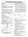
TO SHARPEN
Always observe safety rules when performing any maintenance.
Care should be taken to keep the blade balanced. An
unbalanced btade wi_ cause excessive vibration and eventual damage to mower and engine;
,
The blade can be sharpened with a file or on a grinding
wheel. Do not attempt to sharpen while on the mower.
•
To check blade balance, you will need a 5/8" diameter
steet bolt, pin, or a cone balancer. (When using a cone
balancer, follow tt'e instructions supplied with balancer).
•
Slide blade on to an unthreaded portion of the steel bolt
or pin and hotd the bolt or pin parallel with the ground.
If blade is balanced, it should remain in a horizontal
position, If either end of the blade moves downward,
sharpen the heavy end until the blade is balanced.
NOTE: Do not use a nail for balancing blade. The lobes of
the center hole may appear to be centered, but are not.
BRAKE
OPERATION
If tractor requires more than six (6) feet stopping distance
at high speed in highest gear, then brake must be adjusted.
(See "TO ADJUST BRAKE" in the Service and Adjustments section of this manual).
TIRES
•
.
•
Maintain proper air pressure in al! tires (See "PRODUCT SPECIFICATIONS" on page 3 of this manual).
Keep tires free of gasoline, o1I,or insect control chemicals which can harm rubber.
Avoid stumps, stones, deep ruts, sharp objects and
other hazards that may cause tire damage.
(See Fig. 14)
CENTER HOLE
NOTE: To seal tire punctures and prevent flat tires due to
slow leaks, tire seatant may be purchased from your local
parts dearer. Tire seatant a%o prevents tire dry rot and
corrosion.
BLADE
BLADE
CARE
For best results mower blades must be kept sharp. Replace bent or damaged blades.
BLADE
•
•
,
REMOVAL
(See Fig. 13)
Raise mower to highest position to allow access to
Mades.
Remove hex bolt, lock washer and flat washer secudng
blade.
Install new or resharpened blade with trai}ing edge up
towards deck as shown.
Reassemble hex bolt, lock washer and flat washer in
exact order as shown.
,
Tighten bolt securely (30-35 Ft. Lbs. torque),
iMPORTANT: BLADE BOLT IS GRADE 8 HEATTREATED.
NOTE: We do not recommend sharpening blade- but if you
do, be sure the blade is balanced.
BLADE
_
MANDREL
_ _
--_%_
_
_
I
,oo,,,s,,°
ASSEMBLY
TRAtUNG
/
EDGE
FIG. 14
BATTERY
Your tractor has a battery charging system which is sufficient for normai use. However, periodic charging of the
battery with an automotive charger wilt extend its life.
,
Keep battery and terminals clean.
*
Keep battery bolts tight.
o Keep small vent holes open.
.
Recharge at 6-10 amperes for 1 hour.
TO CLEAN BATTERY AND TERMINALS
Corrosion and dirt on the battery and terminals can cause
the battery to "leak" power.
= Open battery box door.
Disconnect BLACK battery cable first then RED battery cable and remove battery from tractor.
,
Rinse the battery with plain water and dry.
Clean terminals and battery cable ends with wire brush
until bright.
= Coat terminals with grease or petroleum jelly.
,
Reinstall battery (See "CONNECT BATTERY" in the
Assembly section of this manual).
V-BELTS
Check V-belts for deterioration and wear after 1 O0 hours of
operation and replace if necessary. The belts are not
adjustable. Replace belts if they begin to slip from wear.
*A GRADE 8 HEAT TREATED BOLT CAN BE
IDENTIFIED BY SIX LINES ON THE BOLT HEAD.
FiG. 13
TRANSAXLE
COOLING
The fan and cooling fins of transmission
clean to assure proper cooling.
should be kept
Do not attempt to clean fan or transmission while engine is
17 running or while the transmission is hot.
CUSTOMER
o
Inspect cooling fan. to be sure fan blades are intact and
c[ean.
COVER
A_R CLEANER
COVER
tnspect cooling fins for dirt, grass clippings and other
materials. To prevent damage to seals, do not use
compressed air or high pressure sprayer to clean
coolin_3fins.
TRANSAXLE
PUMP
KNOB
WING NUT
FOAM
PRE,-CLEANER
FLUID
The transaxte was sealed at the factory and fluid maintenance is not required for the life of the transaxie. Should the
transaxIe ever leak or require servicing, contact your nearest authorized service cente:idepartment.
ENGINE
LUBRICATION
PAPER CARTRIDGE
AIR CLEANER
BASE
,OIL FILL
CAP/DIPSTICK
Only use high quatity detergent oil rated with API service
classification SF, SG or' SH. Select _.heoil's SAE viscosity
grade according to your expected operating temperature.
AIR
SCREEN
SAEVISCOSITYGRADES
_20_
TEMPERATURE
0°
RANGE
30_
_
40_
ANTICIPATED
60°
BEFORE
80"
NEXT ell
100 °
CHANGE
FIG. 15
O_L DRAIN
PLUG
NOTE: Although multFv[scosity oils (5W30, 10W30 etc.)
improve starting in cold weather, these multi-viscosity oils
wilt result in increased oil consumption when used above
32°F. Check your engine oil level more frequently to avoid
possible engine damage from running low on oil.
,
,r
,
FiG. 16
Change the oil after the first two hours of operation and
every 50 hours thereafter or at least once a year if the
tractor is not used for 50 hours in one year.
A!tR FILTER
(See Fig. t6)
Check the crankcase oil level before starting the engine
and after each eight (8) hours of operation. Tighten oil fill
cap/dipstick securely each time you check the oil level.
Your engine wilt not run properly using a dirty air filter;
Clean the foam pre-cleaner after every 25 hours of operation or every season. Service paper cartridge every 100
hours of operation or every season, whichever occurs first.
TO CHANGE ENGINE OIL (See Fig. 15and 16)
Service air cleaner more often under dusty conditions.
Determine temperature range expected before oil change.
AII oil must meet APi service classification SF, SG or SH.
•
Remove knob and cover.
o
Be sure tractor is on Ievet surface.
•
Remove wing nut and air cleaner from base.
TO SERVICE PRE-CLEANER
,
Oil wilt drain more freely when warm.
Catch oil in a suitable container.
•
Slide foam pre-cleaner off cartridge.
Remove oil fill cap/dipstick. Be careful not to allow dirt
to enter the engine when changing oil.
•
Remove drain plug.
=
After oil has drained completely, replace oil drain plug
and tighten securely.
Squeeze it dry in a clean cloth.
Saturate it in engine oil. Wrap it in clean, absorbent
cloth and squeeze to remove excess oil.
TO SERVICE CARTRIDGE
Gently tap the flat side of the paper cartridge to dislodge dirt. Do not wash the paper cartridge or use
pressurized air, as this wilt damage the cartridge,
Replace a dirty, bent, or damaged cartridge.
Refill engine with oil through oil fit! dipstick tube. Pour
slowly. Do no_ overfill For approximate capacity see
"PRODUCT SPECIFICATIONS"
on page 3 of this
manual
•
Use gauge on oil fill cap/dipstick for checking level.
Insert dipstick into the tube and rest the oil fill Cap on the
tube. Do not thread the cap onto the tube when taking
reading.
Keep oil at"FULL" line on dipstick. Tighten
cap onto the tube securely when finished.
Wash it in liquid detergent and water.
Reinstall the pre-cteaner (cleaned and oiled) over the
paper cartridge.
Reassemble air cleaner, wing nut, cover and tighten
knob securely.
18
'
u,u .......
, r,
'lql .......
,
CUSTO
,nun
CLEAN
AIR SCREEN
(See Fig. 16)
Air screen must be kept free of dirt and chaff to prevent
engine damage from overheating. Clean with a wire brush
or compressed air to remove dirt and stubborn dried gum
fibers:
inspect and replace corroded muffler and spark arrester (if
equipped) as it could create a fire hazard and!or damage.
CLEAN
Replace spark plugs at the beginning of each mowing
season or after every 100 hours of operation, whichever
occurs first. Spark ptug type and gap setting are shown in
"PRODUCT SPECIFICATIONS" on page 3 of this manual.
AiR INTAKE/COOLING
SPARK
AREAS
To insure proper cooling, make sure the grass screen,
cooiing fins, and other externa! surfaces of the engine are
kept €lean at all times.
IN-LINE
Every 100 hours of operation (more often under extremely
dusty, dirty conditions), remove the blower housing and
other cooling shrouds. Clean the cooling fins and external
surfaces as necessary. Make sure the cooling shrouds are
reinstalled.
ENGINE
OIL FILTER
(See Fig. 17)
Replace the engine oil fi_ter every season or every other oil
change if the tractor is used more than 100 hours in one
year.
=
•
•
FUEL FILTER
(See Fig. 18)
®
With engine coot, remove filter and plug fuel line
sections.
-
Place new fue! filter in position in fue! line with arrow
pointing towards carburetor.
-
Be sure there are no fuet line leaks and clamps are
properly positioned.
*
Immediately wipe up any spilled gasoline.
CLAMP
CLAMP
Drain oil from engine crankcase (See "TO CHANGE
ENGINE OIL" in this section of this manual, through
step remove drain plug),
Remove oil filter and wipe off filter adapter.
Apply a thin coating of new engine oil to the rubber
gasket on replacement oil filter,
-
PLUGS
The fuel filter should be replaced once each season. If fuel
fiIter becomes clogged, obstructing fue f owto carburetor,
replacement is required.
NOTE: Operating the engine with a blocked grass screen,
dirty or plugged cooling fins, and/or cooting shrouds removed will cause engine damage due to overheating.
-
•
MUFFLER
FUEL
FILTER
InstalJ replacement oil filter on filter adapter, Turn oit
filter clockwise until rubber gasket contacts the filter
adapter, then tighten filter an additional 1/2 turn.
FIG. 18
Fill crankcase with new oil (See "TO CHANGE ENGINE OIL" in this section of this manual), For approximate capacity see "PRODUCT SPECIFICATIONS" on
page 3 of this manual.
CLEANING
Clean engine, battery, seat, finish, etc. of all foreign
matter.
Start the engine and check for oil feaks. Correct any
leaks before placing engine into full operation,
•
Keep finished surfaces and wheels free of all gasoline,
oil, etc.
•
Protect painted surfaces with automotive type wax.
We do not recommend using a garden hose to clean your
tractor unless the electrical system, muffler, air filter and
carburetor are covered to keep water out. Water in engine
can result in a shortened engine life.
OiL F|LTER
FiG. 17
19
SERVICE
AND ADJUSTMENTS
IIIMII'IIIII
CAUTION:
_
,
•
•
I
.........
........
I1=1,1
II
I
IIIIIII
'1
IH
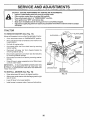
MOWER
(See Fig. 19)
CLUTCH
Mower wi{1be easier to remove from the right side of tractor,
.
-
P!ace attachment clutch in "DISENGAGED" position,
Move attachment Iiff Iever forward to lower mower to its
lowest position,
SUSPENSION
Rolt belt off engine pufley.
o
Disconnect clutch rod from clutch lever by removing
retainer spring,
*
Disconnect anti-sway bar from chassis bracket by
removing retainer spring.
,
Disconnect suspension arms from rear deck brackets
by removing retainer springs.
o
Disconnect front links from deck by removing retainer
springs.
Raise lift lever to raise suspension arms. Slide mower
out from under tractor.
o
/
RETAINER
SPRING
iMPORTANT:
fF AN ATTACHMENT OTHER THAN THE
MOWER IS TO BE MOUNTED TO THE TRACTOR, THE
R,H. AND Loll. SUSPENSION ARMS MUST BE REMOVED
FROM TRACTOR.
TO iNSTALL
HI
Place motion contro! lever in neutra! (N) position.
Depress
clutch/brake
pedal
fully and set parking
brake.
Place
attachment
ctutch
in "DISENGAGED"
position.
Turn ignition key "OFF" and remove key.
Make sure the b|ades and ail moving parts h_ve completely stopped.
D_sconnect spark plug wire from spark plug and place wire where it cannot come in contact
with plug.
TRACTOR
TO REMOVE
IIIIIIII1,11111111
BEFORE PERFORMING ANY SERVICE OR ADJUSTMENTS:
MOWER
ANTI_-SWAY BAR
(See Fig, !9)
,
Raise attachment lift lever to its highest position,
=
Slide mower under tractor with discharge guard to right
side of tractor.
=
Lower lift lever to its lowest position,
Install moWer in reverse order of removal instructions.
RETAINER
SPRINGS
('BOTH SIDES)
FIG. 19
2O
= 'n'
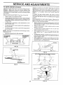
TO LEVEL
MOWER
HOUSING
FRONT*TO-BACK ADJUSTMENT (See Figs, 22 and 23)
mMPORTANT: DECK MUST BE LEVEL SIDE-TO-SIDE, IF
THE FOLLOWING FRONT-TO-BACK
ADJUSTMENT IS
NECESSARY, BE SURE TO ADJUST BOTH FRONT LIt}KS
EQUALLY SO MOWER WtLL STAY LEVEL SIDE-TO-
Adjust the mower while tractor is parked on level ground or
driveway.
Make sure tires are properly inflated (See
_'PRODUCT SPEC1F_CAT!ONS '_on page 3 of this manual).
if tires are over or unde rinflated, you will not properly adjust
your mower.
SIDE_TO_SIDE ADJUSTMENT
SIDE.
To obtain the best cutting results, the mower housing
shoutd be adjusted so that the front is approximately 1/8" to
1/2" lower than the rear when the mower is in its highest
position.
Check adjustment on right side of tractor. Measure distance "D" directly in front and behind the mandrel at bottom
edge of mower housing as shown.
,
Before making any necessary adjustments, check that
both front links are equal in length, Both links should be
approximately 10-3/8".
tf links are not equal in length, adjust one link to same
length as other link.
To lower front of mower loosen nut "E" on both front
links an equal number of turns.
,
When distance "D" is 1/8" to 1/2" lower at front than
rear, tighten nuts "F" against trunnion on both front
links.
•
To raise front of mower, loosen nut"F" from tru nnion on
both front links. Tighten nut "E" on both front links an
equal number of turns.
,
When distance "D" is 1/8" to t/2" lower at front than
rear, tighten nut"F" against trunnion on both front links.
•
Recheck side-to-side adjustment.
(See Figs. 20 and 21 )
°
Raise mower to its highest position.
•
At the midpoint of both sides of mowe r, measure heiRht
from bottom edge of mowerto ground. Distance A' on
both sides of mower shouid be the same or within 1/4"
of each other.
•
If adjustment is necessary, make adjustment on one
side of mower only.
•
To raise one side of mower, tighten lift link adjustment
nut on that side.
•
TO lower one side of mower, loosen lift link adjustment
nut on that side.
NOTE: Each full turn of adjustment nut will change mower
height about 1/8".
•
Recheck measurements
after adjusting.
BOTTOM EDGE
OF MOWER TO
GROUND
BOTTOM EDGE
OF MOWER TO
GROUND
MANDREL
GROUND LINE
FIG. 20
SUSPENSION
ARM
RG. 22
BOTH FRONT LINKS MUST BE EQUAL
LIFT LINK
ADJUSTMENT
IN LENGTH
NUT
FIG, 21
NUT "E"
NUT
FRONT LINKS
21
TRUNNION
FroG.23
SERVICE
TO REPLACE
(See Fig, 24)
MOWER
BLADE
AND ADJUSTMENTS
DRIVE
BELT
o
Measure distance between brake operating arm and
nut "A" or,, brake rod
The mower blade drive bett may be replaced without tools.
Park the tractor on tevet surface. Engage parking brake.
BELT REMOVAL Remove mower from tractor (See "TO REMOVE
MOWER" in this section of this manual),
Work belt off both mandrel pulleys and idler pulleys.
,
Pull belt away from mower.
BELT INSTALLATION o
Install new belt in reverse order of removal,
o
if distance is other than t _3/4", loosen jam nut and turn
nut "A" until distance becomes 1-3/4". Retighten jam
nut against nut "A".
Road test tractor for proper stopping distance as stated
above. Readjust if necessar:¢. If stopping distance is
stiil greater than six (6) feet in highest gear, further
maintenance is necessary. Contact your nearest authorized service centeridepa¢[menL
Make sure belt is in all pulley grooves and inside all belt
guides.
Install mower in reverse order of removal instructions.
MANDREL
PULLEY
Depress clutch/brake pedal and engage parking brake.
TO REPLACE
(See Fig, 26}
MOTION
DRIVE BELT
Park the tractor on level surface. Engage parking brake.
For assistance, there is a bett installation guide decal on
bottom side of left footrest.
IDLER
PULLEYS
•
Remove mower (See "TO REMOVE MOWER" in this
section of this manual.)
•
Remove upper belt keeper.
,
Remove bett from stationary idter and clutching idler.
,
Puti belt slack toward rear of tractor. Carefully remove
belt upwards from transmission input pufley and over
cooling fan blades,
PuII belt toward front of tractor and remove downward
from around engine pulley.
®
MANDREL
PULLEY
,
Install new belt by reversing above procedure.
IMPORTANT:
MAKE SURE UPPER BELT KEEPER IS
POSITIONED PROPERLY BETWEEN LOCATOR TABS.
FiG. 24
TO ADJUST
BRAKE
(See Fig. 25)
Your tractor is equipped with an adjustable brake system
which is mounted on the side of the transaxle.
ENGIN E "---.-_..._
PULLEY
"_--_-._
CLUTCHING
_-_Pl_r"
-_.
-_
,DLER
If tractor requires more than six (6) feet stopping distance
at high speed in highest gear, then brake must be adjusted.
_
LOCATOR
"-.
STATIONARY -_
_
=_. fi_
iDLER
_/1
I
UPPER
WITH PARKING BRAKE "ENGAGED"
/_
....
"_'\
NUT "A"
TRANSMiSSiON
KEEPER
_L
l t/4;,_,
,_ /
I, c
I
ARM
FIG, 2a
DO NOT TOUCH THIS NUT, IF: FURTHER
BRAKE ADJUSTMENT
iS NECESSARY
CONTACT YOUR NEAREST AUTHORIZED
SERVICE CENTEPJDEPARTMENT
FiG. 25
22
BELT
SERVICE AN
ii,l,,iHn,
TO ADJUST
iin=
=
i
MOTION
-=,i
I
=u,n
t
CONTROL
I,,,
=lI,H=r
ADJUSTM
m u= = n
LEVER
STEERING
WHEEL
ALIGNMENT
if steering wheet crossbars are not horizontal (left to right)
when wheels are positioned straight forward,
remove steering wheel and reassemble per instructions in the Assembly
section of this manual.
The motion control fever has been preset at the factory and
adjustment should not be necessary.
If for any reason the motion control lever will not hold its
position while at a selected speed, it may be adjusted at the
friction pack located on the right side of transmission.
•
Park tractor on level surface. Stop tractor by turning
ignition key to "OFF" position, and engage parking
brake.
= Adjust motion control lever by tightening adiustment
locknut one half (1/2) turn.
NOTE: If for any reason the effort to move the motion
control lever becomes too excessive, reverse the above
adjustment procedure by loosening locknut 1/4 to 1/2 turn,
Road test tractor after adjustment and repeat procedure if
necessary.
TRANSMiSSiON
,,
TO ADJUST
(See Fig. 27)
NTS
FRONT WHEEL
TOE-INtCAMBER
The front wheet toeoin and camber are not adiustable on
your tractor. If damage has occurred to affect the front
wheel toe4n or camber, contact your nearest authorized
service center/department.
TO RENIOVE WHEEL
(See Fig= 28)
=
REMOVAL/REPLACEMENT
,
•o
Should your transmission require removal for service or
replacement, it should be purged after reinstatlation and
before operating the tractor. See "PURGE TRANSMIS,
SION" in the Operation section of this manual.
•
FOR REPAIRS
Block up axle securely.
Remove axie cover, retaining ring and washers [o allow
wheel remova! (rear wheel contains a square key - Do
not lose)•
Repair tire and reassemble.
On rear wheels only: align grooves in rear wheef hub
and axle. insert square key.
Replace washers and snap retaining ring securety in
axle groove.
Reptace axle cover.
NOTE: To seal tire punctures and prevent flat tires due to
slow teaks, tire sea_ant may be purchased from your _ocal
parts dealer. Tire sealant also prevents tire dry rot and
corrosion.
WASHERS
RETAINING
RING
ADJUSTMENT
LOCKNUT
I
FtG. 27
AXLE COVER
--_
SQUARE
FIG. 28
23
KEY
(REAR WHEELONLY
)
SERVICE A
TO START ENGJNE WiTH A WEAK
See Fig, 29}
ADJUSTMENTS
BATTERY
TO REPLACE
•
°
•
AND RELAYS
Check wiring. See electrical wiring diagram in the
Repair Parts section of this manuat,
TO REPLACE
TO ATTACH JUMPER CABLES =
Connect each end of the RED cable to the POSITIVE
(+) terminat of each battery, taking care not to short
against chassi&
= Connect one end of the BLACK cable to the NEGATIVE (_) terminal of fully charged battery,
FUSE
Replace with 30 amp automotive4ype plug-in fuse.
fuse hotder is located behind the dash,
TO REMOVE HOOD AND GRILL
(See Fig. 30)
Connect the other end of the BLACK cable to good
CHASSIS GROUND, away from fuel tank and battery.
BLACK cable first from chassis and then from the fully
charged battery.
RED cable last from both batteries.
ASSEMBLY
Raise hood.
-
Unsnap headlight wire connector.
,
Stand in front of tractor. G rasp hood at sides, tilt toward
engine and lift off of tractor.
-
To replace, reverse above procedures.
NEGATIVE TERMINAL
HOOD
WIRE
HEADUGHT
CONNECTOR
\
FIG. 30
CABLES
CHARGED
BATTERY
POSITIVE TERMINAL
NEGATIVE
TERMINAL
FIGo29
24
"The
*
TO REMOVE CABLES, REVERSE ORDER -
TERMINAL
Reptace bulb in holder and push bulb holder securely
back into the ho_e in the backside of the grill
Close hood.
Loose or damaged wiring may cause your tractor to run
poorty, stop running, or prevent it from starting.
IMPORTANT:
YOUR TRACTOR IS EQUIPPED WiTH A 12
VOLT NEGATIVE
GROUNDED
SYSTEM.
THE OTHER
VEHICLE
MUST
ALSO
BE A 12 VOLT
NEGATIVE
GROUNDED
SYSTEM.
DO .NOT USE YOUR TRACTOR
BATTERY TO STAR_ OTHER VEHICLES.
POSiTiVE
Raise hood.
INTERLOCKS
If your battery is too wes_k to start the engine, it should be
recharged,
if "jumper cabtes" are used 'for emergency
starting, fottow this procedure:
-
BULB
Puit bulb holder out of the hole in the backside of the
grilt.
ate explosive ga_;;e$oKeep spat'ks, frame
and
smok[r_gLead-acid
_¢_ater/alsbatteries
away fror_
bat=
CAUTION:
generteries.
Always west eye p[oteotion
when arour_d batter_s.
=
HEADLIGHT
SERVICE A
ADJUSTMENTS
ENGINE
ACCELERATION
TO ADJUST THROTTLE
(See Fig, 31)
CONTROL
=
High speed stop is factory adjusted.
Do not adjust damage may result.
IMPORTANT:
NEVER
TAMPER
WITH THE Er4GINE
GOVERNOR,
WHICH IS FACTORY
SET FOR PROPER
ENGINE SPEED. OVERSPEEDING
THE ENGINE ABOVE
THE
FACTORY
HiGH
SPEED
SETTING
CAN
BE
DANGEROUS.
1F YOU THINKTHE
ENGINE-GOVERNED
HIGH SPEED NEEDS ADJUSTING,
CONTACT
YOUR
NEAREST
AUTHORIZED
SERVICE
CENTER/
DEPARTMENT,
WHICH HAS PROPER EQUIPMENT
AND
EXPERIENCE
TO
MAKE
ANY
NECESSARY
ADJUSTMENTS.
With engine not running, move throttle control lever
from slow (_)
to choke (IX) position. Slowly move
lever from choke ([XI) to fast (,_) position,
Oheck to see if hole in throttle lever and hole in speed
control bracket are aligned.
.
If hetes are not atigned, loosen cable clamp screw and
align the holes by inserting a pencil or a 1/4" drill bit
through both holes.
•
Pull throttle cable up to remove slack and tighten cable
clamp screw, Remove alignment pencil or drill bit.
TO ADJUST
CARBURETOR
-
Move throttle control lever from stow (,,_m.) to fast (,_)
positior_.
If er_gine hesitates
or dies, turn idte fuet
adjusting needle out (counterclockwise)
1/8 turn. Repeat test and continue to adjust, if necessary,
until
engine accelerates
smoothly.
CABLE
The throttle control has been preset at the factory and
adjustment should not be necessary+ Check adjustment as
described below before loosening cable. If adjustment is
necessary, proceed as follows:
.
TEST
CABLE CLAMP
SCREW
(See Fig, 32)
SPEED CONTROL
BRACKET
The carburetor has been preset at the factory and adjustment should not be necessary. However, minor adjustment may be required to compensate for differences in fuel,
temperature, altitude or load. If the carburetor does need
adjustment, proceed as follows:
tn general, turning the adjusting needles in (clockwise)
decreases the supply of fuel to the engine giving a leaner
fueVair mixture, Turning the adjusting needles out (counterclockwise) increases the supply of fuel to the engine giving
a richer fueVair mixture.
THROTTLE
LEVER
f,MPGRTANT:
DAMAGE TO THE NEEDLES AND THE
SEATS IN CARBURETOR MAY RESULT IF NEEDLE IS
TURNED IN TOO TIGHT.
FIG.
NOTE: The carburetor on this engine is tow emission. It is
equipped with an idle fuel adjusting needte with a limiter
cap, which allows some adjustmentwithin the limits allowed
by the cap. Do not attempt to remove the limiter cap. The
]!miter cap cannot be removed without breaking the adjusting
needle.
=
Be sure you have a clean air fiiter and the throttle
control cable is adjusted properly (see above).
=
Start engine and allow to warm for five minutes. Make
adjustments with engine running and shift/motion control
lever in neutral iN) position.
Idle _peed settit_ - With throttJe control lever in slow
(,glb) position, engine should idle at 1750 RPM. If
engine idles too slew or fast, turn idle speed adjusting
screw Jnor out until correct idle is attained.
•
=
•
IDLE SPEED
ADJUSTING
SCREW _-"-'_-_'_"_"-_-'--'-1_
IDLE FUEL
Idle fue! need_
- With throttle control lever in
slow (,ak,) position, turn idle fuel adjustment needle in
(clockwise) until engine begins to die and then turn out
(counterclockwise) untii engine runs rough. Turn needle
to a point midway between those two positions.
Recheck idle speed.
31
/'
;
-"
FIG, 32
Readjust if necessary.
25
"
1
STORAGE
ENGINE
Immediately prepare your tractor for storage at the end of
the season or if the tractor wiil not be used for 30 days or
more.
FUELSYSTEM
iMPORTANT:
IT iS IMPORTANT
TO PREVENT
GUM
DEPOSITS
FROM
FORMING
IN ESSENTIAL
FUEL
SYSTEM PARTS SUCH AS CARBURETOR,
FUEL FILTER,
FUEL HOSE, OR TAr',_K DURING
STORAGE.
ALSO,
EXPERIENCE
INDICATES
THAT ALCOHOL
BLENDED
FUELS (CALLED GASOHOL
OR USING ETHANOL
OR
METHANOL)
CAN ATTRACT MOISTURE
WHICH LEADS
TO SERARATIOH AND FORMATION
OF ACIDS DURING
STORAGE.
ACIDIC
GAS CArpi DAMAGE
THE FUEL
SYSTEM OF AN ENGINE WHILE IN STORAGE.
TRACTOR
Drain the fue! tank.
Remove mower from tractor for winter storage° When
mower is to be stored for a period of time, clean it thoroughly, remove ati dirt, grease, leaves, etc. Store in a
clean, dry area.
,,
o
Ctean entire tractor(See "CLEANING" in the Customer
Responsibilities section of this manual).
,
Inspect and replace belts, if necessary (See belt replacement instructions in the Service and Adjustments
section of this manual).
Q
Lubricate as shown in the Customer Responsibitities
section of this manual.
•
Be sure that aft nuts, bolts and screws are securely
fastened. Inspect moving parts for damage, breakage
and wear. Replace if necessary.
=
Touch up all rusted or chipped paint surfaces; sand
lightly before painting.
Fully charge the battery for storage.
,
After a period of time in storage, battery may require
recharging.
-
Never use engine or carburetor cleaner products in the
fuel tank or permanent damage may occur.
Use fresh fuel next season.
NOTE:
Fuel stabilizer is an acceptable alternative in
minimizing the formation of fuel gum deposits during storage. Add stabilizer to gasoline in fuel tank or storage
container. Always follow the mix ratio found on stabilizer
container. Run engine at least t0 minutes after adding
stabilizer to allow the stabilizer to reach the carburetor. Do
not drain the gas tank and carburetor if using fuel stabilizer.
ENGINE
OIL
Drain oil (with engine warm) and replace with ctean engine
oil. (See "ENGINE" in the Customer Responsibilities
section of this manual),
BATTERY
-
Start the engine and let it run until the fuel lines and
carburetor are empty.
CYUNDERS
Remove spark plug(s).
To help prevent corrosion and power leakage during
long periods of storage, battery cables should be
disconnected and battery cleaned thoroughly (see'q-O
CLEAN BATTERY AND TERMINALS" in the Customer Responsibilities section of this manual).
After cleaning, leave cables disconnected and place
cables where they cannot come in contact with battery
terminals.
=
Pour one ounce of oil through spark plug hole(s) into
cylinder(s).
®
Turn ignition key to"START" position for a few seconds
to distribute oil
=
Replace with new spark plug(s).
OTHER
*
Be sure battery drain tube is securely attached.
-
Do not store gasoline from one season tO another.
,
If battery is removed from tractor for storage, do not
store batter,:/directly on concrete or damp surfaces.
.
Replace your gasoline can if your can starts to rust.
Rust and/or dirt in your gasoline will cause problems.
.
If possible, store your tractor indoors and cover it to
give protection from dust and dirt.
-
Cover your tractor with a suitable protective cover that
does not retain moisture. Do not use plastic, Plastic
cannot breathe which allows condensation to form and
will cause your tractor to rust.
|MPORTANT: NEVER COVER TRACTOR WHILE ENGINE
AND EXHAUST AREAS ARE ST_LL WARM,
26
-
.
-
--
:
......................
..
TROUBLESHOOTING
CAUSE
Will not start
1,
Outof fuel,
2.
3.
4.
5,
6.
7,
Engine not "CHOKED"
Engine flooded.
Bad spark plug.
Dirty air filter.
Dirty _el tilter.
Water In fue!.
8,
9.
Loose or damaged widng.
Carburetor out of adjustment.
Hard to start
Engine will not turn over
Engine clicks but wilt not
start
....
POINTS
!.
2.
3.
4.
5.
6.
7.
properly,
8.
9.
10.
Engine valves out of adju,_tment,
FilJ fuel tank.
See "tO START ENGINE" in Operation section.
Wait several minutes before attempting to start.
Replace spark plug.
ClearVrepiace air filter.
Replace fuel filter.
Drain fuel tank and carburetor, refill tank with fresh
gasoline and replace fuel filter.
Checkell wiring.
See _'TeAdjust Carburetor" in Service Adjustments
section.
Contactan authorized service center/department.
1,
2.
3.
4.
5.
6.
7.
Dirty air filter,
Bad spark p;ug,
Weak or dead battery,
Dirty fue_ filter,
Stale or dirty fuel.
Loose or damaged wiring.
Carburetor out of adjustment.
1.
2.
3.
4.
5.
6.
7.
Clean/replace air filter.
Replace spark plug.
Recharge or replace battery.
Reptace fuel filter.
Drain fuel tank and refill w_th fresh gasoline.
Check al_wiring.
See "To Adiust Carbureto¢' in Service Adjustments
section.
8.
Engine valves out of adjustment,
8.
Contact an authorized service center/department.
1,
2,
3.
4.
Clutch/brake pedal not depressed.
Attachment clutch i.s engaged,
Weaker dead battery.
Blown fuse.
5,
6.
7.
8,
9.
Corroded battery terminals.
Loose or damaged wiring.
Fautty ignition switch.
Faulty solenoid or starter.
Faulty operator presence switch(us}.
1.
2.
3.
4.
5.
6.
7.
8.
9.
Depress clutch/brake pedal.
Disengage attachment clutch.
Recharge or replace battery.
Replace fuse.
Clean battery terminals.
Check all wiring.
CheckJreplace ignition switch.
Check/replace solenoid or starter.
Contact an authorized service center/department.
1,
2.
3,
4.
Weak or dead battery.
Corroded battery terminals.
Loose or damaged wiring,
Faulty solenoid or starter,
1.
2.
3.
4.
Recharge or replace battery.
Clean battery terminals.
Check all wiring.
Check/replace solenoid or starter.
I,
2.
3.
4+
5.
6.
7,
8.
9.
Cutting too much grass/too fast.
Throttle in "CHOKE" position.
Build-up of grass, leaves and trash under mower.
Oi_ alr fi_ter,
Low oil level/dirty oil,
Faulty spark plug,
Dirty fuel fitter.
Stale or dirty fuel.
Water in fuel.
1.
2.
3.
4.
5.
6.
7.
8.
9.
Set in "Higher Cut" position/reduce speed,
Adjust throttle control,
Clean underside of mower housing.
Clean/replace air filter,
Check oil level/change oil.
Clean and regap or change spark plug,
Replace fuel filter,
Drain fuel tank and refill with fresh gasoline,
Drain fuel tank and carburetor, refiii tank with fresh
u
Loss of power
Excessive
1it
CORRECTION
PROBLEM
10.
innlu
vibration
10.
! 1.
12.
t3.
14.
Spark plug wire loose,
Dirty engine air screen/fins.
Dirty/clogged muffler.
Loose or damaged wiring.
Carburetor out of adjustment.
to.
1t.
!2.
13.
14.
I5.
Engine valves out of adiustment,
15.
1.
2.
3.
Worn, bent or loose blade.
Bent blade mandrel.
Loose/damaged part(s).
27
gasofine and replace fuel fi_ter.
connect and tighten spark plug wire:
Clean engine air screen/fins.
Clean/replace muffler.
Check all wiring.
See "To Adjust Carburetor" in Service Adjustments
section.
Contact an authorized service center/department.
t.
2.
Replace bfade. Tighten blade bolt.
Replace blade mandrel.
3.
Tighten toose part(s).
Replace damaged parts.
PROBLEM
CORRECTBON
CAUSE
Engine cont_,naes to tun
when operator leaves seat
with attachment clutch
I.
Faulty operato_osafetyp_esencecontrol system.
1.
Check widng, switches and connectionS.
{f not
corrected, contact an authorized service center/
deparirnent.
engaged
Poor cut- Uneven
_
Mower blades
rotate
1.
2,
3.
4,
Worn, bent or loose biade.
Mowe_ deck not level
Buildup of grass, Ieaves, and trash under mower.
Bent Made ma_drel,
5.
Ctogged mower deck vent hotes from buildup of
grass, leaves, and trash around mandrels,
i.
2,
Replace biade. Tigb.ten biade bolt,
Level mower deck.
3.
4.
5.
Clean underside of mower housing.
Replace b_de mandrel
Clean around m_ndre_s to open vent holes.
=
will not
Poor grass discharge
1.
Obstruction
1.
Remove obstruction.
2.
3.
4.
Worn/damaged mower ddve belt.
Frozen idler pulley.
Frozen blade mandre£
in clutch mechanism.
2.
3.
4.
Replace mower dnve belt.
Replace idler pulley.
Replace biade mandrel
1,
2.
3,
4.
Engine speed too slow,
Travel speed too fast.
Wet grass.
Mower deck not level.
1.
2.
3.
4.
Place throttle control in "FAST" position.
Shiftto slower speed.
Allow grass to dry before mowing,
Level mower deck.
5.
6.
7,
8.
Low/uneven tire air pressure.
Worn, bent or loose blade,
Buildup of grass, leaves and trash under mower,
Mower drive beJt worn.
9.
10.
11,
Blades improperly installed.
Improper btades used.
Clogged mower deck vent hotes from buildup of
grass, teaves, and trash around mandrels.
5.
6.
7.
8,
9.
10.
1t.
Check tires for proper air pressure: ......
Replace/sharpen blade. Tighten blade be_t.
Clean underslde of mower housing.
Replace mower drive belt.
Reinstall b_ades sharp edge down.
Replace with blades listed in this manual.
Clean around mandrels to open vent holes.
Headlight(s)
not working
(if so equipped)
!.
2.
3.
4
5
Switch is "OFF".
Butb(s) burned out.
:aulty light switch
Loose or damaged wiring.
3town fuse.
1.
Turn switch "ON".
2.
3.
4
5.
Replace bulb(s).
ChecWreplace I_ght switch.
Check wiring and connections.
Replace fuse.
Battery will not charge
1
2.
Bad battery cell(s).
Poor cable connections.
I
2.
Reelace battery.
Check/clean eli connections.
3.
4
Faulty regulator (if so equipped}.
Faulty alternator.
9.
4
Rer31ace regulator
Re_lace alternator,
Loss of drive
I.
2
&
Freewheel control in "disengaged" position.
Motion drive belt worn, damaged, or oroKen.
Air trapped in transmission during shipment
or servicing.
I
2.
3.
Place treewheer control in 'engaged" position
Reolaoe motion drive belt.
Purge transmission.
Engine "backfires"
when turning engine
"OFF"
t
Engine throttle contro} not set at "SLOW"
position for 30 seconds before stopping engine.
...
- .......................
28
Move throttle control to "SLOW"
ooeition and altow
re idle for 30 seconds before stopping engine
TRACTOR
= _ MODEL
NUMBER
917.258552
SCHEMATIC
oliio
÷[
RED
-
BLACK
BATTERY
RED
©_D
--
__,
FUSE 30 AMP.
AMMETER
(OPTIONAL)
WF TE
I
/-_
i
_
i
mEO
_
"-1STARTER
I
a_D
--J B
ML_
{
_ CLUTCH / BRAKE
,e
L
[
_
|
_
IGNITION
PEDAL UP)
_H'_:
.
(NOT OCCUPIED)
/7
ILl "_
,-
A
_
"_
F_
(CLUTCH OFF)
}
METER
(OPTIONAL)
' - .......
_
FUELr
__w
UNIT
IGNITION
OIL
BLACK
SPARK
FUELSHUT_OFF
SOLENOID
.
LtGHT_NG
ORANG_
CIRCUIT
"MAKE"
OFF
RUN!LIGHT
G+ M + L
B + L
NONE
A + Y
RUN
B ÷ L
NONE
START
B+ L + S
NONE
(CHARGING
_-
SYSTEM
.
5 AMP AC@
_
_
.'_._L__ _
_I(_N_
3600 RPM_
_
ult'JU_
ALTERNATOR
: .............
_
I:
" 'q
I II
........
J
HEADLIGHTS
O
REMOVABLE
CONNECTIONS
CLIPS
NOTE: IF WIRING INSULATED CLIPS WERE REMOVED FOR
SERVICING OF UNIT, THEY SHOULD BE REPLACED T_O
PROPERLY SECURE YOUR WIRING.
29
DISCONNECTED)
-o-
YOUR TRACTOR IS
|
EQUIPPED WITH A SPECIAL
ALTERNATOR SYSTEM.
L
_owN
THE LIGHTS ARE NOT
CONNECTED TO THE
BATTERY, BUT HAVE THEIR
OWN ELECTRICAL SOURCE.
BECAUSE OF THIS, THE
BRIGHTNESS OF THE LIGHTS
WILL CHANGE WITH ENGINE
SPEED. AT IDLE THE LIGHTS
II
WILL DIM. AS THE ENGINE IS
NON-REMOVABLE
SPEEDED UP, THE LIGHTS
WILL BECOME THEIR BRIGHTEST.
CONNECTIONS
WIRING iNSULATED
SYSTEM
___J_
........
POSITION
BLUE
j
GAP
PLUG
PLUGS ON
_
3 AMP DO @ 3600 RPM
IGNITION SWITON
GROUNDING
CONNECTOR
77
REPAIR PARTS
TRACTOR
- - MODEL NUMBER
917.258552
ELECTRICAL
26
t9
I
20
25
16
!
52
E
3O
REPAIR PARTS
...........
TRACTOR
MODEL NUMBER
917.258552
ELECTRICAL
KEY
NO.
PART
NO.
1
2
3
4
6
7
8
9
16
19
20
21
146140
74760412
STD551025
STD551125
STD541025
109238X '
156417
109596X
153664
STD551125
73350400
147430
22
24
25
4!52J
4799J
146147
26
28
29
30
31
32
33
40
4t
42
43
44
45
52
70
108824X
4207J
121305X
140301
124211X
141226
!09310X
156442
71110408
131563
145673
73640400
121433X
141940
142621
NOTE:
DESCRIPTION
Battery. 12 Volt 30 Amp
Bolt, Hex Head 1/4-20 unc x 3/4
Washer
Washer
Nut
Tube, Plastic, 12"
Case, Battery Mech Hinge
Cramp, .Hose
Switch, _nterlock Push4n
Washer, Lock
Nut, Hex, Jam 1/4-20 UNC
Harness, Light Socket
(hlciudes 4t52J)
Bulb, Ught
Cable, Battery, 6 Gauge, Red, 1 t"
Cable, Battery, 6 Gauge, Red, W/16
Wire
Fuse, 30 Amp
Cable, Ground, 6 Gauge, Black, 12"
Switch, Plunger
Switch, Ignition
Nut, Ignition
Cover, Key Switch
Key, Ignition
Harness, Ignition
Boft, Hex Head, Fin. 1/4-20 x 1/2
Cover, Terminal, Red
Solenoid
Nut Keps BIk Hex 1/4-20 UNC
Ammeter Rectangular 6 Amp
Protection Wire Loop
Harness Engine
All component dimensions given in U.S. inches
1 inch = 25.4 mm
3!
REPAIR PARTS
TRACTOR
CHASSIS
- = MODEL NUMBER
917.258552
AND ENCLOSURES
29
123
28
58
5
12
53
52
55
37
54
10
71
74
3 /
3
32
14
REPAIR PARTS
....
TRACTOR 'o MODEL NUMBER
CHASSIS
917,258552
AND ENCLOSURES
KEY
NO.
PART
NO,
I 159527
2 140356
3 17490612
4 19131216
5 155272,
9 150t56X011
10 STD533710
11 146956
12 145660
13 146962
14 17490608
17 144983X558
18 126938X
25
19131312
26 STD54!437
28 145198X558
29 145200
30 151287X558
3t
139976
38 139886
39 139887
51 7380O400
52 19091416
53
145201
54 17O3O814
55 145202
57 STD522507
58 150127
60 72140606
64 154798
71 73680400
74 73680600
122 157301
123157927
140 150556
142 156095
t43 154966
144 154207
145 156524
146 154334
147 74760412
-5479J
NOTE:
DESCRIPTION
Chassis Assembly
Drawbar
Screw, Thd, Roll. 3/8-16 x 3/4
Washer 13/32 x 3/4 x 16 Gauge
Bumper Hood/Dash
Dash
Bo}t, Carriage 3/8-!6 x 3/4
Panel, Dash, L.H.
Clip Tinnerman Grille P/L
Panel, Dash, R°H.
Screw Thdrol 3/8-16 x 1/2
Hood Assembly
Bumper Hood
Washer !3/32 x 13/16 x 12 Gauge
Nut
Grille w/Clips MS-558
Lens, Grille
Fend/Ftrest Pnt STLT N HLD 558
Bracket, Fender Support
Pivot Bracket Assembly, L.H.
Pivot Bracket Assembly, R,H.
Nut Lock w/Insert 1/4-20 UNC
Washer 9/32 x 7/8 x t6 Ga.
Bracket Grille Pickoff LH
Screw Spiderlock Hex Hd #8-7/8
Bracket Grille Pickoff RH
Bolt, Fin Hex 1/4_20 UNCx .75
Duct Air Engine PtL LT
Bolt Rdhd Sqnk 3/8-16 UNC x 3/4
Dash Lower STLT
Nut Crowntock 1/4-20unc
Nut Crownlock 3/8-t6 UNC
Bracket, Shift STLT
Screw TT #10-32 5 38 Flange
Bracket Chassis Front
Plate Reinforcement STLT
Bracket Swaybar Chassis
Bracket Pnt Footrest STLT
RJod Pivot Chassis/Hood
Screw Torx Hd Thd 5/16-18 UN-2A
Bolt Hex Hd 1/4-20unc x 3/4
Plug, Button
All component dimensions given in U.S. inches
1 inch = 25,4 mm
33
REPAIR pARTSTRACTOR"
"_tooELNUMBER
9_7..258552
53
\
/
77
I
34
55
REPAIR PARTS
TRACTOR
....
- = MODEL NUMBER
917.258552
DRIVE
KEY
NO.
1
2
3
8
t0
15
16
18
19
2!
22
24
25
26
27
28
29
30
31
32
34
35
36
37
38
39
40
41
42
44
45
46
47
48
49
50
5I
52
53
55
56
57
59
PART
NO,
150071
142431
143995
154792
76020416
74490544
73800500
74780616
73800600
130564
145627
73350600
106888X
19131316
76020412
145204
124236X
!30807
t27275X
74760512
155071
120183X
19211616
1572H
123674X
74760644
4470J
154777
1913t312
105706X
110812X
12000039
127783
154604
123205X
74760624
73680600
73680500
105710X
105709X
74760620
140294
140312
KEY
NO.
DESCRiPTiON
Transaxle Assembly
Spring, Return, Brake
Pulfeqy,Transaxte
Rod ,_hift Hydro LT
Pin Cotter 1/8 x 1 CAD
Bolt Hex Flghd 5/16-18 Gr. 5
Nut Lock HexW/ins.
5/16-18 Unc
Bolt Fin Hex 3/8-16 Unc x 1 Gr, 5
Nut Lock HexW/Wsh 3/8-16 Unc
Knob, DeEuxe 1/2-13
Rod, Brake Hydro
Nut, HexJam 3/8-16 Unc
Spring, Brake Rod
Washer
Pin Cotter t/8 x 3/4 CAD.
Rod, Parking Brake
Cap, Parking Brake
Bracket, Transaxfe
Keeper Belt Lh
Bolt Hex Hd 5/16-18 Unc x 3/4
Shaft, Foot Pedal
Bearing, Nylon
Washer
Pin, Roll
Pulley, Idler, Flat
Bolt
Spacer, Split
Keeper, Belt Idler
Washer 13/32 x 13/16 x 12 Gauge
Bearing, Nylon
Washer, Hardened
Ring, Klip
Pulley, idler, V-Groove
BellcrankAssembly
Clutch
Retainer, Belt
Bolt
Nut Crownlock 3/8o16 UNC
Nut, Crownlock 5/16-18 Unc
Link, Clutch
Spring, Return, Clutch
Bolt Hex 3/8-16 x t-1/4
V-Belt, Ground Drive
Keeper, Center Span
61
62
63
64
65
66
70
71
72
73
74.
75
76
77
" 78
81
82
83
84
86
87
88
89
90
9t
92
93
94
95
96
97
98
100
102
103
104
105
106
t!6
118
121
PART
NO.
17490612
8883R
140186
7!170764
10040700
154778
134683
140158
19132012
156347
121199X
121749X
12000001
123583X
121748X
156046
I23782X
19171216
140548
71208
19212016
12000008
154882
124346X
74780536
74780524
142564
140462
144643
4497H
140469
73510600
19111216
141322
73940800
140156
71070516
74780520
72110610
154774
154419
DESCRePT_ON
Screw Thdrol. 3/8-16 x 3/4 Ty. TT
Cover, Pedal
Pulley, Engine
Bolt Hex 7/16-20 x 4 Gr. 5
Washer
Keeper Belt Engine Full Proof
Keeper Belt Engine
Strap Torque Lh Hydro 18/20" T
Washer 13/32 x t-1/4 x 12 Gauge
Strap Torque Rh Hydro 18/20" T
Spacer, Split
Washer 25/32 x 1-1/4 x 16 Gauge
E-Ring
Key, Square
Washer 25/32 x 1-5/8 x 16 Gauge
Shaft Asm. Cross Hydro 20" Tires
Spring Torsion T/A
Washer 17/32 x 3/4 x 16 Ga.
Rod, Tie Hydro 20" Tires
Bushing Rod Strig. 629/632 ID
Washer 21/32 x 1-t/4 x 16 Ga.
Ring Ktip #5304-62
Console, Shift
Nut Self-Thd Wsh-hd 1/4 Zinc
Bolt Fin Hex 5/16-t8 x 2-1/4
Bolt Fin Hex 5/6-18 Unc x 1-1/2
Line Fuel Hydro 4"
•Fan, Hydro 7"
Control Bypass Hydro 20" Tires
Retainer Spring 1" Zinc/Cad
Keeper Bolt Rh Hydro 0750. 18/20"
Nut Keps Hex 3/8-16 Une
Washer 11/32 x 3/4 x 16 Ga.
Washer Bellville ;501D x !.50D
Nut Hex Jam Toplock 1/4-20 Unf
Arm, Control Hydro
Screw Cap Hex 5/16 x 18 x 1
Bolt Fin Hex 5/16-18 Uric x 1-1/4
Bolt Rdhd Sqneck 3/8-16 x 1.25
Spacer Bellcrank
Nyliner Clutching STL
NOTE: All component dimensions
1 inch = 25.4 mm
35
given in U.S. inches
REPAIR PARTS
TRACTOR
STEERING
-- MODEL NUMBER
917.258552
ASSEMBLY
r
/
62
_i
68
67
70
t3
i
•
25
..........
32
/
68
43
28
30
36
REPAIR PARTS
TRACTOR-STEERING
MODEL NUMBER
917.258552
ASSEMBLY
KEY
NO.
PART
NO,
1
2
3
4
5
6
7
8
9
10
I1
13
15
17
18
19
20
2!
22
23
25
26
27
28
29
30
32
36
37
38
39
40
41
42
43
44
46
47
5!
53
54
62
63
65
66
67
68
69
70
12t472X
154427
!56483
157473
6266H
121748X.
19272016
12000029
3366R
156438
STD551t37
154779
73901000
156546
57079
I24035X
126684X
STD551!25
71100410
127501
154406
126847X
136874
19131416
17490612
STD561210
130465
155099
152927
126805X
19133808.
STD541537
100711L
145054
12!749X
15372O
12t232X
6855M
STD541431
73680600
74780520
156594
STD523710
154780
154404
74781044
154429
160367
74780636
NOTE:
DESCRiPTiON
Steering Wheel
Axle Ass_mbty STMP Dropped STL
Spindte Assembly, L.H.
Spind e Assembly, R.H.
Beadng, Race, Thrust, Hardened
Washer 25/32 x 1-5/8 x 16 Gauge
Washer 27/32 x 1-1/4 x 16 Gauge
Ring, K[ip
Bearing, Steering Column
Draglink Extended Stamped
Washer, Lock
Bearing Axle STLTiGT
Nut, Lock, Flange 5/8-11 UNC
Shaft Assembly, Steering
Washer, Thrust .515 x .750 x .033
Support,, Shaft
Washer, Shim 1/4 x 5/8 x .062
Washer
Screw, Hex Socket Head
1/4-20 x 5/8
Pittman Shaft Assembly
Bracket, Steering
Bushing, Link, Drag
Gear, Sector
Washer t3/32 x 7/8 x 16 Gauge
Screw, Thd., Roll. 3/8-16 x 3/4
Pin
Rod, Tie
Bushing, Steering
Screw
Insert, Steering Wheel
Washer 13/32 x 2-3/8 x 8 Gauge
Gripco Nut
Adaptor, Steering Wheel
Boot, Steering Shaft
Washer 25/32 x t-t/4 x 16 Gauge
Extension Shaft Steering LR.LT
Cap, Spindle
Fitting, Grease
Nut Lock Hex w/ins. 5/16q8 UNC
Nut, Crownlock 3/8-t6unc
Bolt Fin Hex 5/16-18 UNC x 1-t/4
Kit Steering Asm Service
Bolt, Fin Hex 3/8q6 UNC x 1 Gr 5
Spacer Axle
Bearing Arm Pittman
Bolt, FEnHex 5/8-I 1 UNC x 2-3/4
Axle, Brace
Spacer, Brace, Axle
Bott, Fin Hex 3/8-16unc x 2-1/4
All component dimensions given in U.S. inches
1 inch = 25.4 mm
37
REPAIR PARTS
TRACTOR
° - MODEL NUMBER
917,258552
SEAT ASSEMBLY
10
5
21
17
KEY
NO.
PART
NO.
1
2
3
4
5
6
7
8
9
10
12
13
14
140123
140551
STD523710
19131610
145006
STD541437
124181X
17490616
19131614
155925
121246X
12!248X
72050411
12
DESCRIPTION
Seat
Bracket, Pivot, Seat
Bolt
Washer 13/32 x 1 x 10 Gauge
Clip, Push-In Hinged
Nut
Spring, Seat
Screw, Thd. Roll. 3/8-16 x 1
Washer t3/32 x 1 x t4 Gauge
Pan, Seat Emboss QCK Conn.
Bracket, Switch Mounting
Bushing, Snap
Bolt, Carriage 1/4-20 x 1-3/8
KEY
NO.
PART
NO.
15
16
17
2t
22
23
134300
121250X
123976X
153236
STD541431
74780814
24
25
26
19171912
127018X
STD551150
DESCRIPTION
Spacer, Split .28 x .88
Spring
Locknut, Flange 1/4 Grade 5
Bolt, Shoulder 5/!6-18 UNC
Nut
Bolt, Hex Head, Fin,
1/2-13 x 7/8 Grade 5
Washer 17/32 x 1-3/16 x 12 Gauge
Bolt, Shoulder 5/16-18 x .62
Washer, Lock
NOTE: All component dimensions given in U.S. inches
1 inch = 25.4 mm
38
REPAIR PARTS
TRACTOR--MODEL
NUMBER 917.258552
DECALS
21
2
9
6
t3
3
18
7
7
18
4
13
1
t5
\\
i
21
16
2O
11
12
5
14
KEY
NO.
PART
NO.
1
2
3
4
5
6
7
8
9
10
11
12
156811
150333
151299
151300
12-113-64
133644
149407
156787
146709
156439
142341
146046
WHEELS
DESCRIPTION
KEY
NO.
Decal, Oper, hstr,
Decaf, Cap Cnsmr Help Line
Decal, Hood, R.H,
Decal, Hood, LH,
Decal Hp Engine
Decal, Customer Maintenance
Dec&l, Side Panel
Decal, Deck Mower EZ3
Decal, Fender, Craftsman
Decal, Fender Danger
Decal, Drawbar Cntd Mvt Hyd Lt
Decal, V-Belt Drive Schematic
13
14
15
16
18
20
21
**-_
---
KEY
NO,
& TIRES
t
2
3
4
4,10
7
11
PART
NO.
147138
136832
146710
138047
151301
149516
156810
138311
154515
154516
160433
160434
PART
NO.
59192
65139
106222X
59904
5
6
7
8
9
10
106732X427
278H
9040H
106108X427
122082X
7152J
11
-_
104757X
144334
DESCRIPTION
Decal, Chassis, 42"
Decal, V-Belt Schematic
Decal, Insert Wheel Steering
Decal, Battery Diehard
Decal, Ins. Hood
Decal, Battery DngdPsn Eng
Decal, Fender Auto Sears Gold
Decal, Lift Handle
Pad Footrest LH STLT
Pad Footrest RH STLT
Owner's Manual, English
OwneCs Manual, Spanish
DESCRIPTION
Valve Cap, Tire
Stem, Valve
Tire, Front
Tube, FrontTire
(Not Provided, Service Item Only)
Rim, Front
Fitting, Grease (Front Wheel Only)
Bearing, Flange (Front Wheel Only)
Rim, Rear
Tire, Rear
Tube, Rear Tire
(Not Provided, Service Item Only)
Cap, Axle
Sealant, Tire 10 oz,
NOTE: All component dimensions
39
! inch = 25.4 mm
given in U.S. inches
REPAIR PARTS
TRACTOR
- - MODEL NUMBER
917.258552
ENGINE
14
\
4
1
7g
33
31
37
29
23
OPTIONAL
EQUIPMENT
Spark Attester
4O
REPAIR PARTS
TRACTOR
- - MODEL NUMBER
917.258552
ENGINE
KEY
NO.
1
2
PART
NO.
147025
17720410
4
!4
15
!6
23
29
31
32
33
35
37
38
137350
13280328
13200300
STD551237
156123
137180
109202X
123549X
123487X
17490512
137040
.......
40
44
124028X
17490412
46
62
77
79
80
81
19091416
STD551131
19101216
M740108025
74760508
128861
DESCRiPTiON
Control, Throttle
Screw, Hex Head, Thread Cutting
1/4-20 x 5/8
Engine, (See Breakdown) Kohler
Model No. CV15S-41526
Muffler
Nipple, Pipe 3/8 NPT x 3-1/2
Elbow, Standard 90 °, 378-18 NPT
Washer
Shield, Heat
Arrestor, Spark
Tank, Fuel
Cap Assembly, Fuel Tank, Vented
Clamp, Hose
Screw Thdro} 5/16-18 x 3-4 Tyt
Line, Fuel
Plug, Oil Drain
(Order From Engine Manufacturer)
Bushing, Snap, Fuel Line
Screw, Hex Washer Head, Thd., RolE.
1/4-20 x 3/4
Washer 9/32 x 7/8 x 16 Gauge
Washer, Lock
Washer 5/16 x 3/4x 16 Ga.
Bolt Hex
Bolt Hex Hd 5/16-18 Unc x 1/2
Nut Flange 1/4-20 Starter Nut
NOTE: All component dimensions given in U.S. inches
1 inch = 25.4 mm
41
REPAIR PARTS
TRACTOR
MOWER
- - MODEL NUMBER
917,258552
LIFT
25 24
23
7
49
5
3O
3
13
150
\
26
4
8
6
13
19
13
\
2O
15
161718
2O
32
15
13_
32
42
20
REPAIR PARTS
TRACTOR
MOWER
=- MODEL NUMBER
917.258552
LIFT
KEY
NO.
PART
NO.
1
2
3
4
5
6
7
8
11
12
13
15
16
17
I8
15946O
159471
105767X
12000002
19211621
120183X
125631X
122365X
139865
139866
4939M
127218
73350800
130171
73800800
19
20
23
24
25
26
27
28
29
30
31
32
49
50
139868
3146R
110807X
19131016
2876H
76020308
!26971X
73350600
138057
150233
140302
73540600
145212
110452X
DESCRIPTtON
Lift Lever Inner Wire Assembly
Shaft Assembly, Lift
Pin, Groove
E-Ring
Washer 21/32 x 1 x 21 Gauge
Bearing, Nylon
Grip, Handle, Fluted
Button, Plunger, Red
Link, Lift, LH.
Link, Lift, R.H.
Retairier Spring
Link, Front
Nut; Hex, Jam 1/2-13 UNC
Trunnion
Locknut, Hex, with Washer Insert
1/2-13 UNC
Arm, Suspension, Rear
Retainer Spring
Nut, Specie[
Washer 13/32 x 5/8 x 16 Gauge
Spring
Pin, Cotter 3/32 x 1/2
Rod, Adjust, Lift
Nut, Hex, Jam 3/8-16 UNC'
Knob, infinite Height Adjustment
Trunnion, Inf Height
Bearing, Pvt, Lift Spherical
Nut, Crownlock 318-24
Nut Hex Flange Lock
Push Nut
NOTE: All component dimensions given in U.S. inches
1 inch = 25.4 mm
43
REPAIR PARTS
TRACTOR
MOWER
,-- MODEL
NUMBER
917;258552
DECK
76
77
71
82
105
!02
52
/
34
33
32
106
31
@
21
113 !1I
22
23
24
_116
\
J
2
25
26
\.
16
119
I
28
118
_13o
29
18
18
21
44
27
REPAIR PARTS,
TRACTOR
MOWER
- - MODEL NUMBER
917.258552
DECK
KEY
NO.
PART
NO.
1
2
3
4
5
6
8
9
10
11
12
13
144393
STD533107
138017
138440
STD624008
130832
850857
STD551137
140296
134149
129895
137645
14 128774
15 110485X
i6
140329
17 72110610
18 72140505
19 132827
20 136888
21 STD541431
22 134753
23 131267
24 I05304X
25 123713X
26 110452X
27 130968
28 19111016
29
131491
30 157722
31 129963
32 129861
33 137266
34 STD533717
35 133835
36 131494
37 19131316
40 STD541437
41 133551
43 140083
44 140088
45 STD624003
46 137729
48 133944
49 133940
50 131340
5t
STD541410
52 139888
53 131845X900
54 133943
55 140084
58
122052X
KEY
NO.
DESCRmPTION
Mower Housing
Bolt
Bracket Assembly, Sway Bar, Front
Bracket Assembly, Sway Bar
Retainer Spring
Arm, Suspension, Rear
Bolt, Hex 3/8-24 x 1.25 Grade 8
Washer, Lock
Washer, Hardened
Blade, Mulching
Bearing, Ball
Shaft Assembly, Mandrel, Vented
(Includes Key Number 6)
Housing, Mandrel, Vented
Bearing, Ball, Mandrel
Stripper, Vented Mower Deck
Bolt, Carriage 3/8-I6 x 1-1/4
Bolt, Carriage 5/16-18 x 5/8
Bolt, Shoulder
Baffle, Vortex
Nut Crownlock 5/16-18 UNC
Stiffener Bracket
Bracket, Deflector
Cap, Sleeve
Spring, Torsion, Deflector
Nut, Push
Shield, Deflector
Washer 11/32 x 5/8 x 16 Gauge
Rod, Hinge
Screw Thd RoIting Wase Head
Washer, Spacer
Pulley, Mandrel
Nut, Toplock, Flanged
Bolt
Fastner, Christmas Tree
Pulley, Idler, Flat
Washer 13/32 x !3/16 x 16 Gauge
Nut Crownlock 3/8-16 UNC
Rod, Pivot, with Nibs
Rod, Clutch, Secondary, with Nibs
Guard, Mandrel, LH.
Retainer
Screw, Thd. Roll I/4-20 x 5/8
Washer, Hardened
Roller Assembly, Cam Follower
Bolt, Shoulder #10-24 Grade 5
Locknut
Bolt, Shoulder 5/t6-18 UNC
Arm Assembly, Pad, Brake
Washer, Hardened
Arm, Idler
Spacer, Retainer
....
58
59
67
68
71
72
73
74
75
76
77
78
79
80
81
82
83
84
85
92
101
102
103
104
105
t06
111
112
113
114
115
116
117
118
119
121
128
129
130
131
132
PART
NO.
140086
141043
149846
144200
142427
t31870
127847
121748X
12000029
128903
127845
154809
127498
153701
73350600
142028
120958X
156084
72140618
STD541437
136420
71161010
19061216
STD551110
130758
2029J
I55197
155198
17490512
73510500
72110504
137644
133957
73930600
19121414
143723
153390
19131312
STD523710
STD533710
19132203
--
130794
--
1454!1
DESCRIPTION
Spring, Torsion Brakes
Guard, TUV Idler
Knob Custom Oval
V-Belt
Rod, Clutch, Primary, with Nibs
Spring, Return
Arm, Clutch, Secondary
Washer 25/32 x 1-5/8 x 16 Gauge
Ring, Klip
Bolt, Shoulder 3/8-16 UNC x 1.44
Keeper, Spring
Lever Asm. Clutch Pri Plm STLT
Bushing, Large, Brass
Spring, Mower Clutch
Nut, Hex Jam 3/8-16 Unc
Trunnion, Adj.
Washer Sintered
Keeper Belt Idler Fixed
Bolt Carriage 3/8-16 x 2-1/4
Nut
Mulcher Cover
Screw
Washer #10
Washer, Lock
Latch Assembly, Bagger
•Nut, Weld
Bracket, Gauge, Wheel L.H.
Bracket, Gauge, Wheel R.H.
Screw Thdrot 5/16-18 x 3/4
Nut, Hex, Keps 5/t6-t8 UNC
Bolt, Carriage 5/16 UNC x 1/2
Bolt, Shoulder
Wheel, Gauge
Nut, Centerlock 3/8-16
Washer 3/8 × 7/8 x I4 Gauge
Bracket
Washer Felt
Washer 13/32 x 13/16 x 12 Ga.
Bolt, Fin Hex 3/8-16 UNC x 1 Gr. 5
Bolt, RDHD SQNK 3/8-16 UNC x 1
Spacer Washer 13/32 I.D. x I-3/8
O.D. x 1/4
Mandrel Assembly (includes Key
Numbers 8-10, 12-t5, 31 and 32)
Mower Deck, Complete (Standard
Deck, Order Separately Mulcher
Plate and Gauge Wheel
Components, Key Nos. I0t-t06
and 111-121)
NOTE: All component dimensions given in U.S. inches
1 inch = 25.4 mm
45
.....
REPAIR PARTS
TRACTOR
HYDRO
GEAR TRANSAXLE
== MODEL NUMBER
- MODEL
NUMBER
917,258552
310-0650
58
34
59
91
26
23
90
g0
52
\
91
4
5
24
"36
113
46
REPAIR PARTS
TRACTOR
HYDRO
GEAR TRANSAXLE
KEY PART
NO. NO.
1
2
3
4
5
6
7
8
9
13
14
15
17
18
19
23
24
25
26
27
28
29
34.
35
36
37
38
39
40
4!
142930
142931
142932
142928
142933
142934
142935
150771
142937
142938
142939
142940
142941
150772
150773
142944
142945
142946
150774
142948
142949
142950
142951
142952
142953
142954
142955
150777
150778
142958
- - MODEL NUMBER
- MODEL
NUMBER
917.258552
310=0650
KEY PART
NO. NO.
DESCRIPTION
Housing, Lower
Assembly, Upper Housing
Seal Lip
Ring, Wire Retaining
Ring, Retaining
Bearing, Shaft Ball
Bearing, Cradle
Beating, Thrust 30 x 52 x 13
Swashp[ate, Variable
Block, Cylinder Assembly
Arm, Trunnion
Seal, Lip
Guide, Slot
Shaft, Motor
Bearing, Thrust 42 x 68 x 16
Block, Cylinder Assembly
Seal, Lip 10 x 25 x 7
Actuator, Bypass
Center Section Assembly Kit
Seat, Lip 26 x 42 x 8
Ring, Retaining
Washer 26 x 35 x !
Oil Filter Element
Arm, Bypass
Ring, Retaining
Arm, Actuating
Pin, Actuating
Bolt 5/16-24 x 1-3/4
Locknut, Hex 5/!6-24 UNJC
Brake Rotor/Stator Kit
43 142884
44 150829
52 142991
53 142961
56 142963
58 142964
59 142965
62 142966
63 142967
64 142920
68 142969
69 144810
83 142971
85 150806
88 142973
89 142974
90 142975
91 142976
92 142977
93 142978
113 142917
114 142918
119 142980
134 144607
135 144608
139 150775
140 150776
DESCRIPTION
Washer 7/16 x 7/8 x .060
Differential Assembly
Washer 3/4x 1.5 x.13
Seal .75 x 1.25 x.250
Shaft, Input
Bolt t/4-20 x 1.38
Pin .50D x.43 ID x.750
Arm, Control
Puck, Dampener
Set Screw
Spring
Stud 5/!6-24
Jackshaft Assembly
Jackshaft
Screw, Cap
Washer 7/16 x 1 x 1/2
Sleeve Bearing
Seat, Wiper
Spring, Block
Washer, Block Thrust
Cap, Vent Assembly
Fitting, O-Ring Assembly
Spacer
Nut, Castle 5/16-24
Pin, Cotter
Spring, Compression
Nut, Hex 5/16-24
NOTE: All component dimensions given in U.S. inches
1 inch = 25.4 mm
47
REPAIR PARTS
TRACTOR
KOHLER
ENGINE
-- MODEL
° - MODEL NUMBER
NUMBER
917;258552
CVl 5S, TYPE NUMBER
PS-41526
2
7
8
6--_
11 --
-1
_--I0
--9
12
9
2
J
_;,j3
/
6
48
/
3
REPAIR PARTS
TRACTOR
KOHLER
ENGINE
-- MODEL
- - MODEL NUMBER
NUMBER
CV15S,
TYPE NUMBER
AiR iNTAKE
KEY PART
NO, NO,
1
12-743-05
2
3
4
5
6
7
8
9
25-34t-02
12-096-24
12-083-08
12-100-0!
X-25-63
12-083-05
12-313-04
12-094-12
10
11
12-072-05
t2-086-0t
12
12-041-02
917 258552
PS-41526
ENGINE CONTROLS
KEY PART
NO. NO.
DESCRiPTiON
Kit, Air Cleaner
(includes Key Numbers 2 thru 12)
Knob, Air Ctear_er Cover
Cover, Air Cleaner
Precleaner Element
Wir_g Nut
Washer, Plain 1/4
Element, Air Cleaner (Includes #7)
Grommet
Base, Air Cleaner
(Includes Key Numbers 9 and 10)
Stud, Mounting Plate M6 x 1.0 x 68
Screw, #10 Hi-Lo Thread
Forming (2)
Gasket, Air Cleaner
1
2
3
'12-079-07
12-237-01
M-0664020
4
5
M-0545016
12-536-09
6
7
8
9
10
1t
12
. 13
14
15
!6
NOT iLLUSTRATED
- - 12-113-53
Decat, Air Cleaner
DESCRiPTiON
M-0443020
SM-0443025
!2_089-11
!2-089-23
12-089-24
M-0641060
SM-0642025
12-090-05
25q58-11
12-079_01
25-158-08
Linkage, Choke
Clamp, Cable
Screw, Locked Socket
M6 x 1.0 x 20 (2)
Screw, Hex Flange M5x .8 x 16
Control, Speed Assembly (Includes
Key Numbers 6 through 9)
Screw, Pan Head M4 x 0.7 x 20
Screw, Pan Head M4 x 0.7 x 25
Spring, Choke Adjust (2)
Spring, Choke Return
Spring, Governor
Nut, Hex Flange M6 x 1.0
Screw, Hex Flange
M6 x 1,0 x 25
Lever, Governor
Bushing, Throttle Linkage
Linkage, Throttle
Bush}ng, Linkage Retaining
CRANKSHAFT
KEY PART
NO. NO.
I
2
12-014-37
12-139-01
EXHAUST
DESCRiPTiON
KEY PART
NO, NO,
Crankshaft
Plug, Cup
1
2
3
4
5
6
BLOWER HOUSING AND BAFFLES
KEY PART
NO. NO.
1
M-0545010
2
3
4
5
6
7
9
8
!0
11
12
13
24-468-10
12-146-07
M-0645020
220534
24-098-05
12-027-32
t2-141-01
12-096-28
25-154-02
M-0545020
12-063-05
M-0645016
14
15
12-063-08
t2-063-01
DESCRiPTiON
Screw, Hex Flange
M5 x 0.8 x t0 (8)
Washer, Plain 1/4
Pfate, Blower Housing
Screw, Hex Flange M6 x 1.0 x 20
Washer, Plain 5/16 (2)
Cover, Pinion
Housing, Blower
Ring, Retainer (2)
Cover
Clip, Mounting (3)
Screw, Hex Ftange M5 x .8 x 20 (3)
Baffle, Intake Side
Screw, Hex Flange
M6 x 1.0 x 16 (2)
Baffle, Cylinder Head
Baffte, Cylinder
DESCRIPTION
M-0829033
!2-041-03
M-0841080
!2-126-!!
12-445-06
M-0645025
Stud, M8 x 1.25 x 33 (2)
Gasket, Exhaust Manifold
.Nut, Hex Flange M8 x !,25 (2)
Bracket, Muffler
Strap, Lifting
Screw, Hex Flange
M6 x 1.0 x 25 (2)
NOT ILLUSTRATED
KEY PART
NO. NO.
---
DESCRiPTiON
12-522-18
12-755-59
Short Block
Gasket Set
RPM Settings:
RPM Settings:
NOTE:
Low Speed: 1500-2000
High Speed: 3200-3400
All component dimensions given in U.S. inches
1 inch = 25,4 mm
NOT iLLUSTRATED
-12o113-64
Deca_, Horsepower
9
_
,
REPAIR PARTS
TRACTOR
KOHLER
FUEL
ENGINE
SYSTEM
-o MODEL
-- MODEL NUMBER
NUMBER
CV15S,
TYPE
917,258552
NUMBER
PS=41526
]
_--29
21
14
22
27
/
15
50
128
REPAIR PARTS
.........................
TRACTOR
KOHLER
ENGINE
-° MODEL
- MODEL
NUMBER
NUMBER
CV15S, TYPE NUMBER
FUEL SYSTEM
KEY PART
NO. NO.
PB-41526
CYLINDER HEAD, VALVE AND BREATHER
KEY PART
NO. NO.
DESCRiPTiON
1
2
3
12_853-56
12-041-02
12_053-56
4
5
6
7
8
9
10
tl
12
13
14
15
16
17
18
19
20
21
22
23
24
25
26
27
28
12-041-0t
12-089-23
12-079-07
12-265-04
X-426-9
25-353-10
25-050-02
47-154-01
12-086-07
12-431-01
12-368-05
12-089-09
12-086-04
12-089-09
12-146-03
25-086-27
12=144-09
12-144-08
12-089-t0
12-146-02
12-337o03
12-757-02
12-04!-05
12-104-01
12-757-09
29
30
3t
32
33
12-041-06
M-0641060
X-25-63
X-22-11
M-0629122
NOT
*-*
-
iLLUSTRATED
12-041-0t
Gasket, Carburetor
12-757-03
Kit, Carburetor Repair
12-518-05
Lead, Solenoid, Black, 5", 14
Gauge, Uninsutated Push-On Tabs
41-518-34
Lead, Ground, Green, 5", 18 Gauge
insulated Grip Barrel Eyelets
--
917.258552
1
2
3
4
5
Kit, Carburetor (includes #2 thru 6)
Gasket, Air C_eaner
Carburetor Assembly
(For information Only - Not
Ava{labte Separately)
(includes Key Numbers 12 thru 27)
Gasket, Carburetor (2)
Spring, Choi<e Return
Linkage, Choke
Deflector, Heat
Clamp, Hose (2)
Line, Fuel, 9"
Filter, Fuel
C_ip, Cable
Screw, Hex Cap 8-32 x 3/8
Sleeve, Insulating
Needle, Idle, Fuel Adjust
Spring, Idle Fuet
Screw, Idle Speed Adjust
Spring, Idle Speed
Plate, Throttle
Screw, Throttle Plate (2)
Shaft, Throttle with Lever and Seat
Shaft, Choke
Spring, Choke
Plate, Choke
Jet, Main
Kit, Float
Gasket, Bowl
Bowl, Fuel
Kit, Solenoid Assembly
(includes Key Number 29)
Gasket, Bowl Retainer Screw
Nut, Hex Ftange M6 x 1.0 (2)
Washer, Plain 1/4
Washer, Lock 1/4
Stud, M6 x 1.0 x 122 (2)
7
8
9
10
12-351-01
12o755-60
12-4!1-01
12-041q0
12-017-01
12-017-02
12-016-0t
12-016-02
12-146-13
12-468-05
12-112-13
12-086-15
1t
12
13
14
15
16
12-089-01
12-!73-01
t2-755-03
X-426-9
12-326-03
M-0645020
17
18
19
20
21
22
23
t2-096-07
235011
24-032 -05
M-0640034
24-194-01
24-186-03
M-0545010
24
25
26
27
12-018-01
12-402-02
12-318-09
X-75-23
6
DESCRIP_ON
Lifter, Valve (2)
Kit, Cylinder Head
Rod, Push (2)
Gasket, Cylinder Head
Valve, Intake, Standard Size
Valve, Intake, .25" Oversize
Valve, Exhaust, Standard
Valve, Exhaust, .25" Oversize
Pinta, Guide
Washer, Plain 13/32
Spacer, Head Bott Exhaust Port
Scrcw, Hex Flange
M!0x !.5 x8! (5)
Spring, Valve (2)
Cap, Valve Spring (2)
Kit, Retainer (2)
Clamp, Hose (2)
Hose, Breather
Screw, Hex Flange
M6 x 1.0 x 20 (5)
Cover, Valve with Nipple
Retainer, Spring
Seal, Valve Stem
Screw, Hex Flange M6 x 1 x 34 (2)
Pivot, Rocker Arm (2)
Arm, Rocker (2)
Screw, Hex Flange
M5x0.8 x t0
. Retainer, Breather Reed
Reed, Breather
Head, Cylinder
Plug, Pipe, Atlen Head 1/8
NOTE: Art component dimensions given in U.S. inches
1 inch = 25.4 mm
51
REPAIR PARTS
TRACTOR
KOHLER
ENGINE
-° MODEL
- = MODEL NUMBER
NUMBER
917,258552
CV15S; TYPE NUMBER
PS-41526
Q--'
;'-ii
J
START|N_
23
22
5_
I
52
REPAIR PARTS
...................
KOHLER
........
TRACTOR
ENGINE
-- MODEL
.-- MODEL NUlVlBER 9i7.258552
NUMBER
CV!5S,
TYPE NUMBER
IGNITION t ELECTRICAL
CRANKCASE
KEY PART
NO. NO.
KEY PART
NO. NO.
1
12-086-14
2
3
4
5
6
7
8
9
10
12-468-03
24q62_03
M-0639016
12-112-01
12-157-02
X-42-t5
12-025-25
41-155-02
M-0548025
11
M-0545010
12
13
14
15
16
17
12-154-02
12-085-03
12-132-02
X-728-1
12-584-01
M=0545020
DESCRiPTiON
Screw, Hex Flange
M10 x 1.5 x 46
Washer, Plain 3/8
Screen, Grass
Screw, Hex Fi8.nge M6 x 1 x 16 (4)
Spacer, Fan (4)
Fan
Key
Flywheel Assembly
Connector (4 Contact)
Screw, Hex Cap
M5 × 0.8 x 25 (2)
Screw, Hex Flange
M5 x 0.8 x 10 (2)
Clip, Stator Harness
Stator Assembly
Spark Plug
Clip, Cable
Module, ignition
Screw, Hex FIange
M5 × 0.8 x 20 (2)
1
2
3
4
5
6
7
8
1
12-038-01
2
3
4
5
6
7
8
9
10
11
12
t3
14
!5
16
17
18
19
20
21
25-755-13
12-153-03
12-t53-02
12-123-04
M-0545020
12-153-01
25-162-07
12-096-03
M-0545016
M-1039025
12-126-02
12-089-03
12-462-01
12-208-01
12-050-01
X-75-10
12-393-01
12-032-04
12-096-02
M-0545016
22
23
12-032-03
SM-0839045
24
12-199-30
20
21
22
23
24
t2-144-24
X-25-102
12-032-01
SM-0631015
12-154-05
11
12
13
OIL PAN t LUBRICATION
KEY PART
NO. NO,
14
15
16
17
18
19
12-032-03
12-522_t8
12-445-02
M*0839025
12-380_03
12-755-49
12-089-18
12-422-08
12-422-09
12-422-10
12-422-!1
12-422-12
12-422-13
12-422-07
12-144-27
12-874-07
12-874-08
12-874-09
12-018-02
t2-108-07
12-'t 08-08
12-108-09
t2-067-05
12-067-06
12-380-01
12-043-05
M-0631005
12-144-02
52-139-09
12-755-64
9
10
NOT ILLUSTRATED
- - 12-518-01
Lead, White, Ground To Kill (19",
18 Gauge, Futly Insu!ated Push-on
Tab and Uninsulated Push-on Tab
Terminals)
DESCRIPTION
Dipstick Assembly
(tncludes Key Numbers 2 and 3)
Kit, Oil Fill Cap (Includes Key #3)
O-Ring, Dipstick
O-R{ng, Upper Oil Fill Tube
Tube, Oil Fill
Screw, Hex Flange M5 x 0.8 x 20
O-Ring, Lower Oil Fil_ Tube
Screen, Oil Pick-up
Cover, Oil Pick-up Screen
Screw, Hex Flange M5 x 0.8 x 16
Screw, Hex Flange Mt0 x t.5 x 25
Bracket, Oil Pump Relief Valve
Spring, Oil Pump Relief Valve
Piston, ©it Pump Relief Valve
Body, Oil Pump Relief Valve
Filter, Oil
Plug, Square Head, Solid 3/8
Oil Pump Assembly
O-Ring, Oil Pump Cover
Cover, Oil Pump
Screw, Hex Flange
M5 x 0.8 x 16 (3)
Seal, Oil (P.T.O. End)
Screw, Hex Flange
M8 x 1.25 x 45 (12)
Pan, Oil
PS-41526
DESCRIPTION
Seal, Crankshaft
Block, Cylinder (Use Short Block)
Strap, Lifting
Screw, Hex Flange M8 x 1.25 x 25
Dowel, Locating (4)
Kit, Camshaft (Includes Key #7 & 8)
Spring, Actuating
Shim, Camshaft, Blue
Shim, Camshaft, Red (A.R.)
Shim, Camshaft, Yellow (A,R.)
Shim, Camshaft, Green (A.R.)
Shim, Camshaft, Grey (A.R.)
Shim, Camshaft, Black (A.R.)
Shim, Camshaft, White (A.R.)
Shaft, Balance
Piston w/Ring Set, Standard
Piston w/Ring Set .25" Oversize
Piston w/Ring Set .50" Oversize
Retainer, Piston Pin (2)
Ring Set, Standard
Ring Set .25" Oversize
Ring Set .50" Oversize
Connecting Rod, Standard
Connecting Rod .25" Oversize
Pin, Governor Regulating
Gear, Governor Assembly
Washer, Plain, 6mm
.Shaft, Governor Gear
Plug, Cup
Kit, Shaft, Governor Cross, with
Clip (Includes Key #20 and 24)
Shaft, Governor Cross
Washer, Plain 1/4
Seal, Governor Cross Shaft
Washer, Plain, 6ram
Clip, Hitch Pin
STARTING SYSTEM
KEY PART
NO. NO.
M-0839070
25-098-03
3
4
5
6
7
8
12-755-54
12-227-06
45-170-03
82-755-28
12_227-11
12_086-25
NOTE:
58
DESCRIPTION
Screw, Hex Flange
M8 x 1.25 x 70 (2)
Starter Assembly
(includes Key Numbers 3 thru 8)
Kit, Drive End
Cap, Drive End
Armature
Kit, Brush and Spring
End Cap, Commutator
Screw, Hex Flange
1/4-20 x 4-5/8 (2)
All component dimensions given in U.S. inches
1 inch = 25.4 mm
SERVICE NOTES
54
SUGGESTED
GUIDE FOR SIGHTING SLOPES FOR SAFE OPERATION
-r
ONLY RIDE UP AND DOWN HILL,
NOT ACROSS HILL
SIGHTING
GUIDE
SIGHT AND HOLD THIS LEVEL WITH
SKY LINE OR TREE.
O1
01
/
15 ° MAX.
i
Ill
Illll
•
II
Operate your Tractor up and down the face of slopes (not
greater than 15°), never across the face. Make turns gradually to prevent tipping or loss of control. Exercise extreme
caution when changing direction on slopes.
IIIIIIIIIIIII
IIIIIII
I
I
II
]
I [l_ _li_llll_ ....
IIIIIIIIIII
I__ ] _[
U!I
.
_:
_£
!
I
®
S /RS
OWNER'S
MANUAL
MODEL NO.
917.258552
15.0 HP
ELECTRIC START
42" MOWER
AUTOMATIC (HYDROSTATIC)
LAWN TRACTOR
Each tractor has its own modeI number.
its own model number,
Each engine has
The modeI number for your tractor will be found on the
model plate located under the seat.
The model number for your engine witl be found on the
blower housing of the engine.
IF YOU NEED
REPAIR SERVICE
OR PARTS:
FOR REPAIR SERVICE, CALL
THIS TOLL FREE NUMBER:
1-800-4-REPAIR
(1-800-473-7247)
AIt parts 1isted herein may be ordered from any Sears,
Roebuck and Co. Service Center/Department and most Retail Stores.
WHEN ORDERING REPAIR PARTS, ALWAYS
FOLLOWING INFORMATION:
" PRODUCT-
GIVE THE
TRACTOR
• MODEL NUMBER - 917.258552
• ENGINE MODEL NO. - CV15, TYPE NO. PS-41526
FOR REPLACEMENT PARTS
INFORMATION AND
ORDERING, CALL THIS
TOLL FREE NUMBER:
1-800-FON-PART
(1-800-366-7278)
--ORCONSUMER ASSISTANCE
HOT LINE, CALL THIS
TOLL FREE NUMBER:
• PART NUMBER
" PART DESCRIPTION
Your Sears merchandise has added value when you
consider Sears has service units nationwide staffed with
Sears trained technicians,,,
professional
technicians
specifically trained to insure'that we meet our pledge to
you, we service what we sell.
1-800-859-5917
160433
Rev. 2
3.24.97TR/JH
Printed in U:S.A,