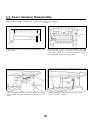
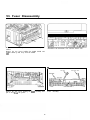
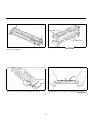
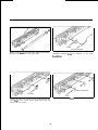
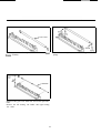
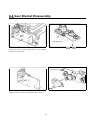
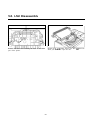
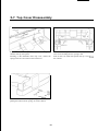
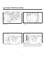
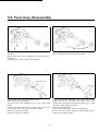
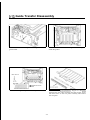
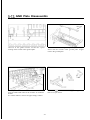
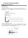
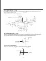
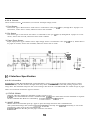
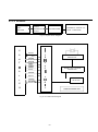
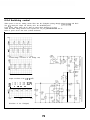
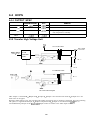
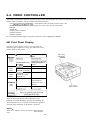
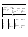
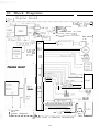
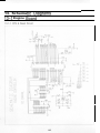
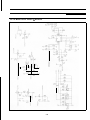
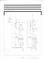
1
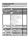
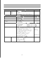
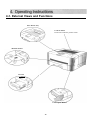
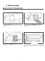
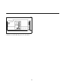
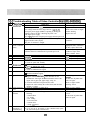
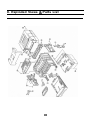
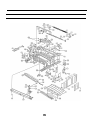
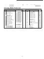
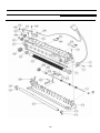
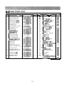
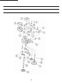
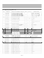
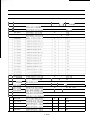
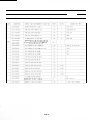
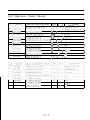
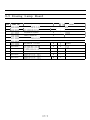
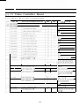
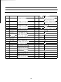
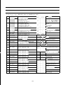
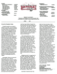
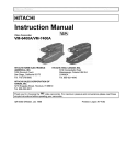
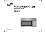
2-4 Recommended Test Equipment
Samsung recommends the following equipment when servicing the Laser Printer.
Digital Multimeter
A digital multimeter with attached LED or LCD 4-digit Panel.
Oscilloscope
A digitizing oscilloscope which can measure more than 1OOMHz
High Voltage probe
A high voltage probe which can measure about less than 1OKV
DCU (Diagnostic Control Unit)
DCU can be supplied from Samsung which can easily shows the engine’s
Error status
Table 2-4-l Equipment List
QUIDCK REFERANCE
DIAGNOSTIC CONTROL UNIC
5PPM LASER BEAM PRINTER
0+
0+
STATUS
MAGNOSTIC
+
cl
ON
OFF
ENTER
UP
DOWN
SHIFT
Figure 241 DCU
28
STOP
2-5 DCU Control
2-5-l DCU Setup
The DCU is used to diagnose Printer malfunctions.
The DCU harness wire(lOpin-todpin) is connected to the Printer engine via:
1) Engine Board connector, CN2 (4pins)
2) (Video) Controller Board connector, 56 (4pins)
Open the Printer’s side cover(=SIMM Cover) and remove the shield cover and connect the DCU
to connector 56 on the Controller Board.
2-5-2 DCU Error messages (LED Display)
If an error occurs, connect the DCU to the Printer. DCU messages will indicates malfunctioning
areas of the machine.
(Consult Service Manual for detailed troubleshooting information)
Display
Error messages
60
OPEN FUSER ERROR
62
LOW HEAT ERROR
64
COVER OPEN ERROR
68
70
OVERHEAT ERROR
NO PAPER OR CASSETTE
71
PAPER JAM0 (CASSETTE PICK-UP TO REGISTER SENSOR)
72
JAM1 (REGISTER SENSOR TO EXIT SENSOR)
73
JAM2 (EXIT SENSOR TO FUSER)
95
LSU NOT READY
29
2-5-3 DCU diagnostic messages (LED display)
After receiving an error message, use the DCU to locate malfunction unit.
Displav
0
1
2
3
4
5
6
I
8
9
10
11
12
13
14
Error messaee
MAIN MOTOR OPERATING SYSTEM
MAIN HIGH VOLTAGE ON (- 14KV)
TRANSFER HIGH VOLTAGE (-) ON
THV (+) REFERENCE VOLTAGE (+9OOV)
DEVSUPPLY HIGH VOLTAGE ON
LSU OPERATING TEST
PICKUP CLUTCH ON
PAPER EMPTY SENSOR TEST
FEED & EXIT SENSOR TEST
COVER OPEN SENSOR TEST
FUSER TEST
HOT BURN TEST
CLEAN (MESSAGE) PRINT
THV TRIGGER & THV ON DUTY
THV PLUS DUTY
2-5-4 DCU Diagnostic Mode
1) Connect DCU to Controller or Engine Board
2) To apply power, simultaneously press tand hold ‘DOWN’, ‘SHIFT’, and ‘STOP’ keys. 78 will display
3) After 2-3 seconds, release the keys. 00 will display
4) Press ‘UP’ or ‘SHIFT+DOWN’ keys until the desired number is displayed in the DCU display.
5) Press ‘ENTER’ to begin operating.
30
6) Example
Select numbers 13 and 14 to adjust the electrophotography trigger voltage.
1: Turn power on by simultaneously pressing ‘DOWN’, ‘SHIFT’, and ‘STOP’ for 2-3 seconds.
2: Press ‘SHIFT+DOWN’ until diagnostic cocde #14 is displayed.
4: Press ‘SHIFT’ and ‘STOP’ to exit routine.
5: Press ‘SHIFT’ and ‘DOWN’ to display diagnostic code #13.
6: Display will antemate between electronc photography trigger voltage and On duty voltage.
7: To end operation, press ‘SHIFT’ and ‘STOP’ keys.
7) DCU Error Message
a) Error messgae ‘60’, ‘THERMISTOR OPEN ERROR’
Error message ‘62’, ‘LOW TEMPERAURE ERROR’
Error message ‘68’, ‘OVERHEAT ERROR’
Action:
1) Measure Fuser’s Thermistor resistance
Normal Thermistor resistance is 2-3 ohms (1 lOV), 6-10 ohms (220V)
2) Confirm Fuser Lamp operation
3) Measure Engine Board resistances at QlOl (Triac Thyrister)
4) Replace Engine Board Q 10 1
5) Replace Engine Board Q3 (KSC 1008-Y)
6) Replace Engine Board PC 15 1 (Triac Photo Coupler)
b) Error message ‘70’, ‘PAPER EMPTY’
Action:
1) Check for paper in cassete tray
2) Replace 0P2 Sensor (Photo Interrupter)
3) Confirm Feed Clutch operation (mode ‘06’)
4) Replace Feed Clutch or Engine Board’s 44 (KSC 1008-Y)
c) Error message ‘7 1’) ‘PAPER JAM- 1’
Action:
1) Check for paper in cassette tray
2) Check for Pick-up unit wear
3) Replace OP 1 sensor (Photo Intermpter)
31
d) Error message ‘72’, ‘PAPER JAM-2’
Error message ‘73’, ‘PAPER JAM-3’
Action:
1) Confirm that normal paper is being used
2) Check for Paper Jam in Fuser
3) Replace sensor ‘SW 1’ on Engine Board
4) Check for Fuser Roller contamination
8) Error message ‘95’, ‘LSU READY ERROR’
a) Confirm normal readings at Engine Boards, QS (KSC1008-Y)
b) Replace LSU
32
3. Product Information
3-1 Specifications
3-l -1 Engine(ML-80)
Specifications are correct at the time of printing. Product specifications are subject to change without notice.
I
Item
1.
Specification & Description
VlL-80
Engme
Remarks
Small Footprint
Desktop Page Printer
I
3. Print Speed
ppm(page
per minute)
At Copy Mode
A4 Size, 5% Character Pattern)
Resolution
frue 600 X 600 dpi(dot per inch)
Source Of Ltght
,aser Diode (LSU: Laser Scanner Untt)
Print Method
\Jon-impact
Feed Method
3assette & Manual
Feed Stde
side Loading
Paper Handling (input)
L
Electrophotography
Left Adjust
Size
0
Standard : A4, Letter, Legal, B5, Executive
0 Envelope : manual feed only
)I
0 Universal type
Length : 150 - 356 mm
W i d t h : 90-216mm
k Weight : For Cassette, 60 - 90 g/in’
For Manual, 60 - 120 g/m’
t Recommended Paper
USA: X420, X4024, NEKOSA, BOISE CASCADE
EC: REFLEX, ADAGIO
Transparancies:
3M (CG3300 or 3360)
Label: AVERY 53XX series
I. Paper Handling (output)
:ace Down : 150sheets
Tace Up : lsheet
50-sheet Tray
1 I F e e d Capactty
!50-sheet Tray and one opttonal 250-sheet Drawer
3etween 25seconds
112. Warm-up Time
113. Ftrst Print Time
setween 25seconds
114. Power Rating
\C 100-I 2OV/220-240V (* 15%) 50Hz/60Hz (+ 3%)
r
r---
15. Power Consumption
16.
‘eak: 720W
luring Printing
Power Saving Consumption
luring Sleeping
,ess
: l50WH (Average)
: Max 1 SW
than 28W during I hour at first
18. Certification & C o m p l i a n c e
3E,
TUV, SEMKO, NEMKO, DEMKO, C-tick, CClB
FCC, UL, CSA, CDRH, CB, MEEI
Noise
For EPA
Vane
1 I7 P o w e r Swatch
19. A c o u s t i c
ML-84/85G
ML-84/85G plus
ML-85, ML-85 plus
Standby
Less than
Operating
Less than 47dB
29dB
33
Class B for EMC
Specification & Description
item
3. Reliability
MPBJ
2,500 pages/75g Paper
MPBF
30,000 pages
MTBF
2,250 hours
Remarks
Jam Rate
(MTBF = 7.5hours X 20days X MPBF /Monthly Use)
1. Toner Supply
Print Cartridge
2. Expected Life Span
100,OOOsheets
For machine
3. Operating Environment
Temperature : 10 - 30 “C
Normal:22 “C 65%
4. Storage Environment
Temperature : 0 - 35 “C
5. Weight
Net : Max 9.3kg
Humidity : 30 - 80 %RH
Humidity : IO - 90 %RH
Gross : Max 10.5Kg
5. External Dimension
ML-84/85G, QwikLaser 84/856
360(W) X 367(D) X 176(H) mm
ML-85, QwikLaser 85
360(W) X 367(D) X 188(H) mm’
Ml-84 pIus/85G plus
360(W) X 375(D) X 176(H) mm’
ML-85 plus
360(W) X 367(D) X 188(H) mm’
Life Span : 5,000 pages, 5% Pattern and 50% Duty
7. Print Cartridge
Developing : Non-magnetic Contact Developing
Charging : Conductive Roller Charging
Negative(-)
Density Adjustment : 3steps (Light, Medium, Dark)
PWM Control
Toner Supply Method Exchanging The Developer
Toner Checking Sensor : None
Transfer System: Conductive Roller Transfer
Fusing System : Temperature & Pressure
Erasing Method: Light Using LED
Ozone Emission : Less than O.IPPM
8. Packing
Main Kit
Printer
I Set
Cassette
1 Piece
1 Piece
Developer Cartridge
Guide Manual and Diskettes
1 Piece
Power Cord
33-l
Quenching Lamp
3-l-2 ML-84, ML-84 plus or QwikLaser 84
Specifications are correct at the time of printing. Product specifications are subject to change without notice,
And ML-84 plus has the new front cover.
Specification & Description
Item
Interface Engine
SAMSUNG ML-SO
Resolution
WPS : 600 X 600 dpi
Remarks
PCL4.5 : 300 X 300 dpi
Emulation
PCL4.5 (Compatible with HP LaserJet IIP)
Including the driver
Mtcrosoft W PS(W indows Printing System)
Font
7 bitmaps
CPU
Motorola MC68322-20MHz
RAM MEMORY
Standard : IM or 1.5M bytes
Optional SIMM Module :
For IM Standard : 4, I6 Mbytes
For 1.5M Standard : 4, 16 Mbytes
* These SIMMs are compatible with the Computer’s,
R O M
1 Mbyte (Font + Program)
EEPROM
5 12bytes
Front Control Panel
4LEDs & 1 key
0. Interface
Bidirectional Parallel Standard
NVRAM
Centronics
- IEEE1284 COMPATIBLE MODE
- IEEE1284 NIBBLE MODE
- IEEE1284 BYTE MODE
- IEEE1284 ECP WITHOUT RLE
Use ECP cable
- IEEE1284 ECP WITH RLE
Serial Interface Optional
RS232C
- 300,600, 1200,2400,4800,9600, 19200,38400,
57600, I1 5200 bps
- XON/XOFF, DTR/DSR Protocol
- Robust XON for XON/XOFF
I. Copy Capacity
Enable up to 999
2. Interface Switching
Automatic (Serial & Parallel)
3. Interface Time Out
1 step is I second from 20 seconds to 5 minutes.
(Zero is disable)
4. Jam Recovery
Jam 0, 1, 2 according to the Jam position
The recopy of Jam 0, 1 is default.
The recopy of Jam2 is optional.
(Don’t use Jam2 recovery under WPS status.)
5 AEP
Emulation switching according to Emulation code.
6. Engine Interface Error
All LEDs blink when communication is error
7. Status Monitor
Bidirectional Status Feedback
Animation for printing
8. PRS Buffer
755Kbytes
9. Top Margin
4.23 f 2.0 mm
WPS only
PC L Pattern
33-2
3-l-3 ML-85, ML-85 plus or QwikLaser 85
Specifications are correct at the time of printing. Product specifications are subject to change without notice
And ML-85 plus has the new front cover.
Item
Specification & Description
I
Interface Engine
SAMSUNG ML-80
Resolution
WPS : 600 X 600 dpi
Emulation
PCL5e (Compatible with HP LaserJet SP)
Including the driver
4F o n t
1 Remarks
Microsoft WPS(W indows Printing System)
1 bitmap
45 scalable (35 intelligent, 10 truetype)
5C P U
Motorola MC68322-20MHz
6 RAM MEMORY
Standard : 2Mbytes
Option SIMM Module : 2, 4, 8, 16 Mbytes
* These SIMMs are compatible with the Computer’s,
R O M
2Mbyte (Font + Program)
EEPROM
5 12bytes
Front Control Panel
4LEDs & lkey
0. Interface
Bidirectional Parallel Standard
NVRAM
Centronics
- IEEE1284 COMPATIBLE MODE
- IEEE1284 NIBBLE MODE
- IEEE1284 BYTE MODE
- IEEE1284 ECP WITHOUT RLE
Use ECP cable
- IEEE1284 ECP WITH RLE
Serial Interface Optional
RS-232C
- 300, 600, 1200,2400,4800,9600, 19200, 38400,
57600, 115200 bps
- XON/XOFF, DTR/DSR Protocol
- Robust XON for XON/XOFF
1. Copy Capacity
Enable up to 999
2. Interface Switching
Automatic (Serial & Parallel)
3. Interface Time Out
1 step is 1 second from 20 seconds to 5 minutes.
(Zero is disable)
4. Jam Recovery
Jam 0, 1, 2 according to the Jam position
The recopy of Jam 0, 1 is default.
The recopy of Jam2 is optional.
(Don’t use Jam2 recovery under W PS status.)
5. AEP
Emulation switching according to Emulation code.
6. Engine Interface Error
All LEDs blink when communication is error
7. Status Monitor
Bidirectional Status Feedback
Animation for printing
8. PRS Buffer
9. Top Margin
WPS only
755Kbytes
1 PCL Pattern
1 4.23 * 2.0 mm
33-3
3-l-4 ML-85G, ML-85G plus or QwikLaser 85G
Specifications are correct at the time of printing. Product specifications are subject to change without notice.
And ML-S% plus has the new front cover.
Specification & Description
Item
1. Interface Engine
SAMSUNG ML-SO
2. Resolution
WPS : 600 X 600 dpi
Remarks
Computer 16Mbytes RAM : 300 X 300 dpi
3 Emulation
Including the drover
PCL4 (Compatible with HP LaserJet II)
4. Font
HP LaserJet II Internal fonts
5. CPU
None (ASIC dependent on host computer)
6. RAM MEMORY
Standard : O.SMbytes
7
ROM
None
8
EEPROM(=NVRAM)
9 Front Control Panel
IO. Interface
S/W Driver
Microsoft WPS(Windows Printing System)
No option memory
ML-85G, ML-85G plus
None
QwikLaser 85G
X24COl P
ML-85G, QwikLaser 85G
5 LEDs only
POWER LED
ML-85G plus
4 LEDs only
READY LED ON
Bidirectional Parallel Standard
Centronics
- IEEE1284 COMPATIBLE MODE
- IEEE1284 NIBBLE MODE
- IEEE1284 BYTE MODE
- IEEE1284 ECP WITHOUT RLE
Use ECP cable
- IEEE 1284 ECP WITH RLE
Serial Interface : None
I I Copy Capacity
Enable up to 999
12. Jam Recovery
Jam 0, I, 2 according to the Jam position
The recopy of Jam 0, I is default.
The recopy of Jam2 is optional.
(Don’t use Jam2 recovery under WPS status.)
13. Engine Interface Error
All LEDs blink when communication is error
14. Status Monitor
Bidirectional Status Feedback
Animation for printing
115. PRS Buffer
755Kbvtes
33-4
WPS only
4-1. External Views and Functions
Face Down Tray
Control Panel
Each LED indicates printer status.
\
\-
Manual Feeder
Cassette
Cover Open Button
35
Facu up Tray
Open Face up Tray and it will
stacks one page.
Parallel Connector
It connects Computer
parallel port
Air Flow hole
Emits internal
thermal air
5. Disassembly
5-l. Controller Disassembly
Remove the SIMM cover.
Push the tab down and pull the SIMM cover away from
the printer.
Remove the two ribboa connectors on the video
controller board.
37
Remove the screw in upper left comer of the metal
panel, then remove the panel to expose the video
controller board.
c
/
Pull the rear metal panel out and slowly slide the video
controller out of the LBP and put it on a flat surface.
38
5-2. Cover Housing Disassembly
Remove the Drum unit, and place it in a place isolated from direct sunlight.
wire panel
Turn the printer’s front to you then lift the door and
remove the two screws. If the printer has the Cleaning
roller, there should be a connection between OUT of
Cleaning board and IN of Cleaning roller.
Locate and remove the two screws along the rear side
of the printer.
From underneath the door, using your thumb, as shown,
pull the hook to the left and then pull out the cap wire
panel.
39
Remove the Panel PBA harness and locate it not to
prevent you from working.
To remove the entire cabinet, release the hook that is
near the bottom and towards the right front side of the
cabinet. To do this, use both hands to elevate the front
of the printer, push the frame lock inward while you
pull the cabinet outward.
40
The cabinet also has a lock on the inlet side. Push the
inlet inward and pull the cabinet upward. Gently pull
the cabinet outward to release the lock as shown in the
diagram.
53. Fuser Disassembly
If you have not already done so, remove the printer
cabinet.
Remove the two screws holding the SMPS Shield and
lift the shield up and away from the SMPS.
Disconnect the thermistor wire and the heater wire.
,
AC wire
\
Remove the four screws holding the fkser assembly and
pull it away from the printer.
41
Fuser Assembly.
thermistor wire
Release the lock holding the actuator and lift one end of
the actuator and then the other end up and away from
the fuser assembly.
Remove the screw at the end of the f&er assembly and
pull the right electrode off the fuser assembly.
Gently, pull the lamp out of the heat roller.
Remove the two screws around the thermostat as
shown in the diagram.
Lift the thermostat out of the f&er assembly and left
electrode.
42
Upper Fuser Frame
Lower Fuser Frame
Remove the four screws holding the upper and lower
fuser frame together.
Pull the upper and lower fker frames apart.
Gear Exit-Laud
Pull off and reserve the gear exit-land the CS ring.
Pull the heat roller up and out of the upper fuser fkame.
43
Remove the firser gear from the right end and the
bearings from each end of the heat roller.
Gently lift the spring lock point to release the
thermistor assembly Corn the underside of the upper
fuser frame.
Locate the two exit rollers on the underside of the
upper Iuser Came. Gently lift the sprint lock points and
remove the exit rollers.
Locate and remove the three guide claws and springs.
44
Pressure Roller
Lift the pressure roller up and out of the lower fuser
fi-ame assembly.
Remove the gear exit from the end of the pressure
roller.
Remove the left bearing exit Roller and right bearing
exit roller.
45
Remove the two pressure roller bearings and their
springs.
5-4. Gear Bracket Disassembly
Along the power inlet side of the printer, locate and
remove the seven screws which hold the gear bracket
assembly on the printer.
Detach the motor harness from the PM.
Gear Bracket Assy -_)
M&or Bracket
Remove the three screws holding the motor bracket to
the gear bracket assembly and pull the motor away.
46
Pull up on the gears individually to remove them.
On the gear train, remove the belt pulley and CS ring to
remove the impella. Other gears on the gear train have
permanently welded gear locks.
Remove the two screws on the motor bracket to
separate the motor from the motor bracket.
The OPC Ground can be removed after taking off the
gear bracket.
47
5-5. LSU Disassemblv
Remove the three screws holding the LSU in the lower
part of the printer.
48
Detach the 5-pin scanner motor wire then lift the LSU
while you detach the 6-pin LD wire.
5-6. Shaft-Exit Disassembly
If you have not already done so, remove the ICU
Shield.
Release the exit bearing on both sides of the exit shaft.
Roller exht
\
Holder exit face down
Lift the exit shaft up and away from the printer.
Locate and remove the face down exit spring, face
down exit holder and exit roller.
49
5-7. Top Cover Disassembly
If you have not already done so, remove the printer
cabinet and cap wire panel.
Working on the underside of the top cover, release the
spring hook lever and remove the hook lever.
C/O B&on
Remove the C/O button by pressing in the hook and
pulling the button and its spring out of the cabinet.
50
To remove the top cover from the cabinet, remove the
four screws holding the two spring-C/OS.
Pull out the C/O shaft and separate the top cover Tom
the cabinet.
5-8. Engine PCB Disassembly
If you have not already done so, remove the printer
SMPS shield.
Remove the eight screws which hold the PCU
assembly.
Unlock the pickup roller from the solenoid.
Locate the pickup roller stopper under the solenoid’s
actuator. Unlock the stopper by pressing it forwards to
power inlet. Pull the PCU assembly out of the printer.
51
Detach the motor wire from the motor connector.
Unplug the LSU wire and the ICU wire from the PCU
assembly.
To remove the power inlet assembly, remove the screw.
Unlock the inlet by pressing the top and bottom sides of
the inlet and pull it out from the PCU shield.
Unplug the AC input connector. Remove three screws
from the PCU assembly and separate the PCU from the
PCU shield.
52
5-9. Feed Assy Disassembly
.
Roller feed driver /
If you have not already done so, remove the PCU
assembly.
Remove the three screws holding the feed assembly in
the printer.
Pull the pickup roller off the feed assembly.
Pull the pickup roller and feed roller off their shafts
after spreading the hooks holding the shafts.
.
Unhook and remove the small feed spring.
Detach the small feed holder.
Pop the small feed subholder out of the small feed
holder.
Remove the small feed roller and the large feed roller
and separate them from their idle feeder shafts.
Detach the large feed spring.
Detach the large feed holder.
53
.
Pop the large feed subholder out of the large feed
holder and remove the large feed roller and its idle
feeder shaft. Spread the hook of the pickup gear’s shaft
and pull off the pickup gear drive.
Remove the pickup gear.
Pull off the pickup lever and the pickup spring.
Remove the two pickup bearings and the feeder gear.
Remove the feeder grounds.
5-10. Guide Transfer Disassembly
Remove the four screws securing the transfer guide
inside the printer.
Remove the screw securing the motor ground to the
gear bracket.
Motor Ground
w Guide-transfer
Slide the saw plate assemoty stopper to rne rert.
Separate the saw plate assembly and the stopper. Press
the three locks on the saw plate assembly and release
the saw plate.
Left the transfer guide up and out of the printer.
54
5-I 1. Erasing Lamp Disassembly
Remove the two screws holding the quenching lamp
assembly in the printer.
5-I 2. Transfer Roller Disassembly
Press the locking tabs at both the left and right sides to
release the transfer roller.
55
Remove the transfer roller holder, transfer roller spring,
and inner transfer roller bushing.
5-13. GND Plate Disassemblv
GND Plate
Unscrew at the guide transfer. Locate the 3-point
locking of the transfer roller ground plate.
Lift the transfer roller ground plate by widening the
frame and the transfer roller ground plate stopper.
remove the ground plate.
w
Feed
Carefully lift the feed-sensor actuator and remove it
from its holder. Both sides of the actuator are locked to
holders.
In a similar manner, remove the paper empty actuator.
56
Release and lift out the feed sensor, paper empty sensor
and cover open sensor.
6. Special Circuit Description
6-l. Engine Control Board
6-l-l Main Parts
6-l-l-l Reset Operation
Reset circuit initializes CPU when power is turned on and prevents CPU from unstable operation caused by
unstable power source. It consists of comparator IC LM393, resisters and condensers which determine reset timing.
When dc 3.8V or higher voltage is applied to #3 pin of LM 393, RESET signal goes HIGH and CPU starts initialize
operation.
CPUPINRS
4 122ms l
6-l-l-2 Fuser Temperature Control
Fuser temperature control circuit reads thermistor voltage through CPU pin ##45 (P5.0) and turn on or off mser
through CPU pin #38 (P6.4) and transistor Q3 (KSC945) according to thermistor value. Thermistor is device whose
resistance changes according to temperature of heat roller. As temperature increases, the resistance of thermistor
decreases. LM393 is used for preventing heat roller from overheating.
57
6-l-l-3 Motor Driving Circuit
SLA7029M receives phase signal from CPU and generates plused signal for main motor driving and controls
driving currents through R5 and R6.
It adopts constant current unipolar driving method
6-l-l-4 Solenoid Driving Circuit
Solenoid controls the paper pick up clutch. It is operated on +24V and control signal from CPU #22 pin (P3.2).
Q4(KSC 1008) is driver transistor and D 1 (IN4003) protects Q4 from switching off noise pulse.
CLUlCH D
CPUPhN22
6-l-l-5 Cover Open Sensing
When cover is closed, CPU pin #48 (P5.3) is HIGH, Otherwise Pin #48 is LOW.
58
6-l-l-6 Sensor
There are three sensor - Feed Sensor, Exit Sensor and Paper Empty sensor.
1) Feed Sensor
Feed sensor type is Photo Sensor. Feed sensor is connected to CPU pin #46 (P5.1) through R15. If paper is on
feed sensor, sensor state is LOW, otherwise sensor state is HIGH.
2) Exit Sensor
Exit sensor type is leaf switch. Exit sensor is connected to CPU pin #47 (P5.2) through R30. If paper is on exit
sensor, sensor state is LOW, otherwise sensor state is HIGH.
3) Paper Empty Sensor
Paper empty sensor type is Photo sensor. Paper empty sensor is connected to CPU pin #/49 (P5.4). When there is
no paper in cassette, sensor state is HIGH, otherwise sensor state is LOW.
RlO
100
FEED
lCCFW48
PEWTY
TO CPUW
EXIT
TO cPw47
EXIT SEWS
SW1
6-I -2 Interface Specification
6-1-2-1 Overview
SAMSUNG LASER BEAM PRINTER (called ENGINE) can be comected to the image control device (called
CONTROLLER) with the interface through which they check their status and control the printing sequence and
image data. The ENGINE transposes the received image data from the CONTROLLER into visible image on paper.
There are two kinds of interface signal as follows.
1) STATUS SIGNAL
/READY indicates whether the ENGINE is ready to print, or not.
/CMSG is the command data from the CONTROLLER, /EMSG is the status data from the ENGINE as response
for the command data. Both are controlled by /CCLK, /CBSY, and /EBSY signals.
2) IMAGE SIGNAL
PRINT makes the ENGINE pick up a paper to print the image data from the CONTROLLER.
The synchronized image data (called /VDATA) by /PSYNC vertically and /HSYNC horizontally is sent to the
ENGINE by video clock of the CONTROLLER.
/EXITPAP indicates that the previous paper clears the exit sensor.
59
6-l-2-2 Structure
VIDEO
LBP
- INTERFACE - CONTROLLER
ENGINE
LOGIC
EXTERNAL DEVICE (PC,
HOST COMPUTER)
Fig. 6-i-l System Block Diagram
I
C
N
/READY
0
l
T
__!f!?%___
.-_
/CMSG
_______-_---_---
l
ICCLK
________-_-__--,__rEssv_____
l
.__
ICBSY
________________
l
/PRINT
________________
*__!PSvr?C____
l
__.
L
NDATA
________________
l
L
L
,__!Hs\/NC____
__.
0
(_ _ _!u(ITpAP _.
__.
G
N
T
R
0
E
R
PRINTING TIMING
GENERATOR
E
R
F
A
C
ENGINE TEST PATTERN
GENERATOR
E
SELECTOR
I
C
Fig. 6-1-2 Interface Block Diagram
60
ariC
I I EM
0
U
T
P
U
T
INPUT AC NOMINAL
22OVACf 12OVAC
MINIMUM
198VACl90VAC
MAXIMUM
264VACll32VAC
INPUT AC CURRENT
MAX 1.5AJ2.5Arms
INRUSH CURRENT (20 DEGREE)
MAX 35A P-P
LINE REGULATION
207
24v
&3%
5V
5v
+2%
24V
-3%-+10%
l 3%
LOAD REGULATION 24V
5v
5v
RIPPLE NOISE 24V
0.C.P
0.V.P
REMARK
include the heater current
120mv
PEAR 400mV
5v
50mV
PEAR 1OOmV
24V
2.7A*lO%
5v
SA(FUSE)
25V
33v
5v
5.6V
6-2-2 The SMPS supplies two different DC voltage sources, +5V and +24V
OUTPUT
+5v
+24V
APPLICATION
1. Logic Parts
Engine Board
2. LSU
Controller Board, Panel
1. Main Motor
2. Solenoid
Pickup
3. HVPS
4. Heater Input Drive
5. LSU motor
AC INPUT
REMARK
1. Heat Lamp
6-2-3 Fuser Control circuit
Fuser controlled by the “fuser on” signal.
When the mser on signal rises triac in the Photo Triac
(pc151) is turn on.
Then trigger input signal supplies into the gate of the
Triac (QlOl), Triac is turn on.
78
Clutch
6-2-4 Switching control
When power is turn on, starting current flows into the UlOl(pin6) passing through ZDlOl(R106)
The It’s totem-pole output can directly drive the MOSFET(Q102).
If the supply voltage drops, the IC shuts its output down when VCC=8.7V.
When the under voltage lockout circuit operates, the CS pin goes low to reset the IC.
Refer to power device data book (related document).
Current/voltage waveform of the FET(Q 102)
Output waveform of the Ul 0 1 (pin
.,. ._ . . .
,JJ” 1: :. ‘: :.’ : : .: _ .
/dn
-
-
-
_.
.
Waveform of the UlOl(pin7)
Fig. 1-3 Switching Control Block Diagram
79
and R107.
6-3 HVPS
6-3-l OUTPUT SPEC
PRINTING/INITIAL
REMARK
DCU
BIAS/SUPPLY
THV “_”
-3gov
-38OV
-lKV
-1KV
THV I’+”
variable
+975v
by the operating environment
EX) temperature, humidity
MHV
-1.4KV
-1.4KV
63-2 Transfer High Voltage Unit
vcc
A
T/C PLUS PART
T/C-OUT
NP
PWMJNPUT
0
Ns
”
0
P.W.M
CONTROL
PART
)
RL 1
RL 2
T/C MINUS PART
f
THV_EN
NP
n
lL4
Ns
RL 3
THV Control Block Diagram
THV output is constituted ‘I+” output and “-” output. “-” output is for clean the OPC drum. “+” output use is for
draw toner on the paper.
When the THV enable is low, the switching TR (Q202) is turned on and “-” output is generated. Soon the switching
TR (Q203) is supplied PWM input, “+” output is duplicated to “-” output in accordance with 4203 turn on.
The fundamental principle of the BIAS/MHV output control is similar to the THV output control.
80
6-4. VIDEO CONTROLLER
The chapter presents the features offered by this printer and describes the electrical operation of the ML-85 Laser
Printer Video Controller, which includes the following topics.
CPU (MC68322/XC68322FT20) -- Note that the 85G series does not have the CPU.
ROM (Program and Font) -- Note that the 85G series does not have the ROM.
*DRAM
EEPROM
Display panel interface
Engine interface
Parallel interface
l
l
l
l
l
l
For a more detailed description of printer operations, refer to Operator’s Guide.
641 Print Panel Display
The ML-85 Laser Printer Video Controller uses the
following light sequences to keep you informed of the
current status of the printer.
( Steady On
Double Blink ever
2-3 sets
P A P E R Blinks
Amber
Steady on, (with
LED
ERROR on steady)
MANUAL
Amber
LED
ERROR 1
Red
LED
Blinking
Steady On (with
ERROR on)
Blinking
Steady on (with
) Online and ready to 1
Panel Key
and LEDs
Wating with data in
printer
Paper Out
Paper Jam
Manual Feed
Recoverable error,
press button to
continue or wait
timeout.
Unrecoverable error,
From Feed function:
With the printer ONLINE and the READY LED
blinking or Double Blinking; pressing and holding the
KEY button down for 4 seconds will cause the printer to
print any data remaining in the printer’s memory.
NOTE :
There is no function of key at ML-85G (QwikLaser
85G).
81
Top Cover
Open Button
6-4-l -1 Model Comparison
New Cabinet
OLD Cabinet
ML-85 or
ML-85G or
ML-85 plus
ML-85G plus
Qw i kLaser 856
Qwiklaser 85
Advancedold type NEW
NEW
1. Top Cover Old type
4 LEDs, 1 key
5 LEDs
4 LEDs only
4 LEDs, 1 key
&
ML-85G
ML-85
2. Controller ML-85
ML-66G-t
ML-85G is not R61
ML-85G plus is
Board
and EEPROM.
not
QwikLaser85G is
R61 and EEPROM.
R61 and EEPROM
ML-85G,
ML-85 plus
ML-85,
ML-85G plus
3. Setup
QwikLaser85G
Driver
QwikLaser85
Cart on/
6-4-l-2 OP Panel Layout
ML-85 or
Qwi kLaser 85
(
ML-85G or
QwikLaser 856
>
f
E-85 plus
/
‘\
0 ERROR (Red)
0 ERROR
0 MANUAL (Yellow)
0 MANUAL (Yellow)
0 PAPER (Yellow)
0 PAPER (Yellow)
0 READY (Green)
0 READY (Green)
(Red)
ML-85G plus
\
0 ERROR (Red)
0 MANUAL (Yellow)
0 MANUAL (Yellow
0 PAPER (Yellow)
0 PAPER (Yellow]
0 REAOY (Green)
0 READY (Green)
0 POWER (Green)
J
c
J
L
81-1
J
7-3-2 Troubleshooting Table of Video Controller Board(ML=84/85/85G)
ErrorType
No
1 Power Error
Repair
Check List
Power cord connection
Vcc voltage (nominal is +5V) level.
Vcc voltage should be in the range between +4.8 - t5.2V
An engine power supply (SMPS) is operating by hearing the
rotating sound of fan after connecting the power cord.
The engine power supply
AC and 5V output fuse in engine power supply unit after power off.
2 Cable Error
Mutual connection of engine, panel connector cable (7 pin) and
engine interface cable (24 pin).
The pins of connector is straight.
3 Main Board Error Any component damage on a video controller board.
(Video Controller
Board)
Any foreign conductive chips of solder or material is on the video
controller board or is laid between IC pins after power off.
4 Reset Error
n Reset signal. Normallly high during operation.
5 CPU Clock Error 40.0Mhz
6 Video Clock Error 30.075Mhz
7 Panel Error
. Check the connecton of panel cable.
n Check the panel PCB assembly.
8 DRAMError
w Check the DRAM address signals.
n Check the DRAM data signals.
9 EEPROM Error
n Check the EEPROM clock signals.
n Check the EEPROM data signals.
10 ROM Error
n Check the ROM chip select signals and read signal.
w Check the ROM data signals.
11 Engine Error
w Fusing Unit Error : &mister, heat lamp, etc.
n Engine communication error : Video controller can not
communicate with engine PCU board about the status of the
engine such as paper jam, paper empty, ready, etc.
n Check the connection of engine interface cable.
n Replace the video board by the verified board, and check the
operation of printer.
n Check the operation of printer driver.
12 Parallel Interface
Error
n Check the printer cable (bidirectional function?)
13 Engine Related
n Please refer to the ML-85 engine service manual about the
Problems
following.
Thermal Error
No heating
Over heating
LSU beam Error
Scanner Error
Fixing Ass’y Error
n Please refer to the user’s manual.
14 General
descriptions of
n If you can not fix the trouble of video controller board, replace
troubleshooting
the video board by the verified board.
l
l
Connect the power cord.
Replace SMPS unit.
Refer to the section of engine
trouble shooting.
Replace the fuse.
Connect the cable to the
connector.
Repair or replace it with
appropriate tools. If unable to
do this, replace main board.
Remove any foreign
conductive chips on the
video controller board.
TIL compatible input
TTL compatible input
Messages appear on PC
SCreen.
At first turn off printer than
turn it on again.
Refer to engine trouble
shooting section.
Refer to User’s manual
Replace the printer cable.
Messages appear on PC
screen.
At first turn off printer then
turn it on again.
l
l
l
l
95
Replace the board.
8. Exploded Views 81 Parts List
96
W
._
@iim_
=JY3
103
8-1 Cover & Panel Ass’y
q
No.
Description
or l%l A/S (After Service) enable
Q’ty
Code No.
0 A/S disable
Drw No.
A/S
1
1
1 PMO-COVERMAIN
1 JC72-4C922A
I
1
I
101
I @I
I
2
I
SPRI%CS:PI0.7,Dl2.4
1 6107-ooo117
I
1
I
102
I IEI
PMO-lWI'ID_ClO
)
JC72-40336A
I
1
PMO-COVER_SIMM
1 JC72-40329A
I
1
I
104
I I@
PMO-COVEUXIT
1
JC72-40343A
)
1
I
105
) El
1 MEC-HWSING,(XIVER:QL-84
1 JC75-1091&A
1
1
1
106
1 @I
I3 I
I4 I
I 5 I
1 6
I
103
1
m
(
1
MEC-HOUSING,CO\‘FR:QL-85
1 JC75-10935A
)
1
1
106
1
q
1
1
MEC-HCUSING,COVER:QL-8%
1 JC75-109344
1
1
1
106
(
q
1
1
MEC-tUJSING,CO\‘W:ML-84
1 JC75-10918X
1
1
I
1
I
I
1 JC75-10918M
MEC-HCUSING,CUER:h
r- I
1
1
1
106
I
1
106
I
1 w
1
q
MEC-HOUSING,COVER:h PLUS
JC75-10926A
1
106
q
MECfKWSING,CT)\IER:M
JC75-10918s
1
106
i@
JC75-10927A
1
106
q
1
q
MEC-IKZUSING,COVER:ML-8%
PLUS
pMo-BUI’mJ’~:ML-84/85,QL-84/85,
ML-8418518% PLUS
7
1
I
JC72-403654
1
1
1
109
1
1
II PMO-BUITCNSANFL:ML-85G,QL-8%
JC72-403%B
I I
JC92-@346A
1
1
1
JC94%985A
1
1
I 110 I
) JC72-40325A
I
1
(
111
I @I
( 6107~133
I
1
I
112
IB
1 JC72-40335A
I
1
I
113
( @I
1
JC72-40335A
I
1
I
113
Im
12 I HINGE-HSGL
I JC61-BO2m
(
1
I
114
IB
I~~/HINGE-HSG R
J C61+0209A
I
PBA-PAN%4Lf!D:ML-84/85,8L-84/85,
ML-84/85//8% PLUS
8
I
) PBA-PANEL$L&D,NO KEY:ML+%,QL-8%
I
PMC-m
9 I
I
10 I SPRING-ES
I
11
I
PMo-~A~~:ML-84/85/85G,QL-84/85/85G
I PMO-STACKEKSlJE%:ML-84l85l8%
I
PLUS
1 JC7C-10228A
1 14 1 IPR-SHAFTCOVER OPEN
I
1
--
1
1 1 (
116
(
1
I 1 6 1 COM,SPRINGC/O,R
1 831 523031CA
1
1
1 1 7 1 PMC-CAP_Pm WI~:~-~is5/85c,QL-s4/85/85G
1 JC72-403384
1
1
I
1 JC72-41056A
I
1
I
I
18
PMO-CAPJm WIREML-84/85/85G
PLUS
SCRI+TAPTI’IE:FVH,+,B,M3
1 6003m
98
I
115
)
118
)
q
,
) ml
) @I I
119
( !@I I
I
1000
)
\@I(
119
I
1
q
117
1
I
I
1
I
/o
q
I
831 523031CB
II
1
1 @I
110
COM,SPRINGC/O,L
I 15
109
I
I ml I
8-2 Assy Frame Parts List
No.
1
2
3
4
5
6
7
8
9
10
11
12
13
14
1.5
16
17
18
19
20
21
22
23
24
25
26
27
28
29
30
31
32
33
34
35
36
37
38
39
40
41
42
-
Parts Name
ROLLER-TRANSFER
BUSH TR INNER
SPRING T/R, L
GEAR-TRANSFER
GND-TRANSFER, PLATE
HOLDER-TR BEARING, L
HOLDER-TR BEARING, R
SPRING PLATE TR
GEAR-EXIT
BEARING-EXIT, F/DOWN
RUBBER-EXIT
SHAFT-EXIT
GEAR-EXIT/U, ID
SPRING-EXIT, F/DOWN
ROLLER-EXIT
HOLDER-EXIT, F/DOWN
EARTH PLATE FU
GROUND G/TR
TERMINALwV2
TERMINAL H/V 1
SPRING H/V
SPRING-PLATE GDEV
GUIDE-DEV, L
GUIDE-DEV, R
FRAME-BASE
GROUND-OPC
GROUND MOTOR
ACTUATOR-FEED
ACTUATOR-EMPTY
FOOT-RUBBER
ACTUATOR C/O
SPRING C/O SENSOR
ASSY-ERASE, LAMP
BKT-ERASE
GROUND-ICU
SHIELD-ICU
SHIELD-COVER SIMM
GUIDE-TRANSFER
INSULATOR-G/TR
PLATE-SAM
HOLDER-SAM PLATE
SHIELD-CAP WIRE
Code No.
811492004AA
821492008AA
83 1 522060BA
821492054AA
813492011AA
82149208OAA
82149208OAA
813492025AA
82149203OAA
811492007AA
821492081AA
821492074AA
821492032AA
83 1 522050DA
821492054AA
821492054AA
8 13 49200AA
JC70- 10008A
935 81004OAA
935 8 10040BA
83 1 522042JA
JC61-7OOOlAA
JC61-20001AA
JC61-20003AA
JC72-60011A
813492013AA
JC70- 10007A
821492003AA
821492002AA
831313026AA
821492089AA
831521073AA
JC93-20007A
JC70- 10002A
JC70- 10006A
813492021AA
813 492034AA
813492016AA
JC72- 10002A
813492057AA
821492057AA
JC70- 10003AA
Li?!t1
2
2
1
1
1
1
1
1
2
3
1
2
3
3
3
1
1
2
1
3
2
1
1
1
1
1
1
1
2
1
1
1
1
1
1
1
1
1
1
1
1
100
Dtw No.
1
2
3
4
5
6
7
8
9
10
11
12
13
14
15
16
17
18
19
20
21
22
23
24
25
26
27
28
29
30
31
32
33
34
35
36
37
38
39
40
41
42
Material
CLOROHYDRINE %,FE
POM (CE-20), BLK
sus304 WPS, 0 0.5
POM BLK
sus304 to.3
PC BLACK
PC BLACK
SUS304 CSP 3/4H, to.2
DURACON M90
POM NTR
EPDM 60”
ABS GF20% BLK
DURACON M90
SUS304 WPB, 6 0.5
POM BLK
ABS GF20% BLK
SUS CPS3/4H to.2
SUS301 CSP 1/2H TO.2
SUM 24L Ni
SUS304 WPB $0.4
SUS304 CSP3/4H, to.2
POM BLK
POM BLK
ABS VO GF20% BLK
SUS304 CSP3/4H to.2
SUS301 CSP 1/2H TO.2
ABS HB BLK
ABS HB BLK
CR60 VO GRAY
ABS VO BLK
SUS304 WPB 0 0.3
_
SECC, to.5
SECC T=0.8
SECC to.5
SECC to.5
SECC t0.6, 45%
PVC LSO80 SHEET to.3
sus304 CSP to.1
PC BLK
SECC, to.6
101
_
”
“.
_’
‘_
__
.,
\_,_j.,
8-3 Assy Motor Parts List
NO.
QfY
Dtw No.
Material
Als
1
ASSY-MOTOR
Parts Name
JC92-60004A
1
-
-
/a
2
STEP-MOTOR
953 280066AA
1
301
3
BRACKET-MOTOR
813492017AA
1
302
SECC tl.2
q
4
GEAR- 132125
821402026AA
1
303
DURACON M90
[XI
5
GEAR-125/18
821492025AA
1
304
DURACON M90
q
6
GEAR-FEED DRV
821492034AA
1
305
DURACON M90
Ixi
7
8
GEAR-OPC DRV
GEAR-IDLE OPC
82140203OAA
821492036AA
1
1
306
307
DURACON M90
DURACON M90
[XI
!I
Code No.
PM TYPE(7.5”)
[xi
9
GEAR-IDLE, FTJ
821492038AA
1
308
POM SW-01
10
GEAR-FUSER, DRIVE
821492035AA
1
309
DURACON M90
q
11
GEAR PULLEY
821492024AA
1
310
DURACON M90
[XI
12
13
BELT IMPELLER
ASSY IMPELLER
831 721004DA
811 721004DA
1
1
311
312
EPDM
PULLEY/IMPELLER/BEAR
[xl
[x1
14
BRACKET-GEAR
813492OOlAA
1
313
SECC tl.2
ixI
15
O-RING
603 l-000004
2
314
@ 3.0, t1.2
[x1
16
POLYWASHER(I1)
603 l-000006
1
315
4 3.0xt0.5
[XI
17
POLYWASHERQ)
603 l-000005
2
316
9 i3.0 x 4 05.0
Kl
102
(I.
222
103
8-4 Fuser Parts List
Code No.
w
1 ASSY-FUSER, 1 IOV
2 ASSY-FUSER, 220V
3 FRAME-UPPER,FU
4 SPRING EXIT F/UP
5 ROLLER EXIT F/UP
6 ELECTRODE-FU, L
7 THERMOSTAT
8 CBF-HARNESS, LAMP
9 GEAR-EXIT/L, ID
10 GEARFUSER
11 H/RBEARING,L
12 WRBEARING, R
13 H/ROLLER
14 LAMP-HALOGEN
15 LAMP-HALOGEN
16 ELECTRODE-F&R
17 FRAME-LOWElqFu
18 P/R BEARING
19 SPRING P/R
20 P/ROLLER
2 1 GROUND-PLATE, FU
22 SPRING-THERMISTOR
23 EXIT ROLLER L
24 BEARING EXIT FU, R
25 BEARING EXIT FU, L
JC93-30001A
JC93-30001B
821492022AA
813 492024AA
82149209OAA
815 492OOlAA
4712-000001
JC39-40007A
82 149203 1AA
821492023AA
821492051AA
821492088AA
815492088AA
4713-000001
47 13-000002
8 15 492002AA
821492021AA
821492044AA
83152206OAA
811492OllAA
813 492014AA
813492026AA
1404-000001
811492OlOAA
821492006AA
1
1
1
2
2
1
1
1
2
1
1
1
1
1
1
1
1
2
2
1
1
1
1
1
1
DIW No.
201
202
203
204
205
206
207
208
209
210
211
212
212
213
214
215
216
217
218
219
220 I
221
222
GEAR-EXIT, FU
ACTUATOREXIT
GUIDE-CLAW
SPRING-CLAW
821492005AA
82149203OAA
821492OOlAA
JC6120005A
6107-00008
1
1
1
4
4
223
224
225
226
227
No.
26
27
28
29
30
Parts Name
104
rdatedal
PBT GF30% BLK
SUS304 CSP-1/2H to.15
POM M90-02, BLK
C52 1P to.5
PW-2N, 160°C
3P, 475/275MM, WHT
DURACON M90
NY66, GF33%
PPS RBA3 13
PPS RBA3 13
AL+PTFE, TEFLON
115V, 600W
22OV, 600W
C52 1OP to.8
PBT GF30% BLK
PPS RBA3 13
SUS304 WPB Q 0.9
SUM22tHTVt~~COATING
SUS CSP 1/2H to.2
SUS CSP 1.2H to.2
17o’c
SUM24L+CR
POM (CE-20) BLK
POM BLK
PEBAX
POM BLK
LCL4024(PEEK+PTFE+C!F)
SUS304 WPB
Ns
IXI
IXI
[XI
0
[XI
cl
IXI
q
0
IXI
rzI
lzl
IXI
[XI
!zl
Ix]
IXI
Ix1
[XI
q
q
cl
lxl
[XI
IXI
[XI
lxi
[XI
q
Ix1
105
No.
1
2
3
4
Parts Name
ASSY PICK-UP
GEAR-PICK UP
SHAFT-PICK, UP
BEARING-PICK-UP
Code No.
Dtw No.
JC93-4000 1A
82 149204 1AA
8 13 49203OAA
821492007AA
w
1
1
1
4
Material
401
402
403
LNI’ LUBLILOY R
SUM24L, Nl
POM (CE-20) BLK
AIS
Ixi
Ix]
q
Ix1
65
7
SPRING P/UF’
P/P
LEVEL
GND-FEED
831
523031DA
821492064AA
813 492OlOAA
1
1
405
404
406
SUS304
WPB $0.5R
LNT’
LUBLILOY
SUS304 CSP 1/2H, to.15
kz
8
9
10
11
FRAME-FEED
HOUSING-PICK, UP
RUBBER-PICK, UP
ROLLER-FEED, DRIVE
82149202OAA
821492062AA
821492082AA
821492071AA
1
1
1
1
407
408
409
410
PC GF30% BLK
ABS HB BLK
EPDM 30”
POM BLK+URETHAN
lxl
IXI
Ix]
12
13
14
15
16
17
18
19
20
21
22
GEAR-FEED
GEAR-P/UP, DW
SHAFT-FEED
SPRING-FEED, SMALL
HOLDER-FEED, SMALL
SUB HOLDER-FEED, SMALL
ROLLER-FEED, SMALL
ROLLER-FEED, LARGE
SHAFT-FEED, IDLE
HOLDER-FEED, LARGE
SPRING-FEED, LARGE
82 1492033AA
82 149204OAA
813492028AA
831 521073BA
831521073BA
821492077AA
82 1492073AA
821492072AA
813492029AA
821492055AA
83 1 522060EA
1
1
1
1
1
1
1
2
3
1
1
411
412
413
414
415
416
417
418
419
420
421
DURACON M90
DURACON M90
SUN 24N NI
SUS304 WI’B, <D 0.6
ABS GF20% BLK
PON NTR
POM NTR
POM BLK
SUM 24L Ni
ABS GF20% BLK
SUS304 WPB, @ 0.8
IXI
(XI
[XI
[XI
[XI
(XI
Ix]
IXI
[XI
106
q
q
q
txl
107
8-6 Cassette & LSU & Developer Ass’y
PMO-FRAME CASSETTE
1
Q’ty
Drw No.
A/S
1
500
q
Q’ty
.Drw No.
A/S
ML-C800(E)
1
900
q
ML-C810(E)
1
900
I@
Description
No.
UNIT-Hl:ha-80.11244RPM
Code No.
JC59-105OlA
Code No.
Description
No.
1
OLD CARTRIDGE
2
NEW CARTRIDGE: CLNhOPC
: NO CLN&OPC
108
8-7 Engine Board
8-7 - 1 PCB Revision 4.8 & 5.1 Comparison
Ver .
Code No.
Description/Specification
V4.8
JC41-10012A
PCB-ML,ENGINE(X):ML-80(X)
v5.1
JC41-100128
PCB-ML,ENGINE:ML-80+
V4.8
2001-000812
R-CARBON:5,6Kohm,5%,1/8W
v5.1
JC39-405llA
CBF-HARNESS:ML-80,JUMPER
v4.8
0401-000005
DIODE-SWITCHING:lN4148
v5.1
0401-000005
DIODE-SWITCHING:lN4148
v4.8
2001-000660
R-CARBON:33Kohm,5%,1/8W
v5.1
2001-000660
R-CARBON:33Kohm,5%,1/8W
V4.8
2001-001145
R-CARBON(S):4.7Mohm,5%,1/2W
v5.1
2009-001042
R-METAL GLAZE:4,7Mohm,l%,l/4W,AA,TP,3x9
V4.8
2001-001252
R-CARBON(S):2Mohm,5%,1/2W
v5.1
2009-001041
R-METAL GLAZE:2Mohm,l%,l/4W,AA,TP
V4.8
2201-000326
C-CERAMIC,DISC:2.2nF,lO%
v5.1
2202-000186
C-CERAMlC,MLC-AXIAL:2.2nF,5%,50V,NPO,
V4.8
3405-000167
SWITCH-MICRO:5V,lmA,2.lgf
v5.1
0604-000229
PHOTO-INTERRUPTER:TR,-,-,-,BK
V4.8
2009-001026
R-METAL GLAZE:4.7Mohm.l%,1/4W,AA,TP,3x9
v5.1
2009-001041
R-METAL GLAZE:4.7Mohm.l%.1/4W,AA,TP,3x9
v4.8
2004-002001
R-METAL:l2.lKohm,l%,1/8W
v5.1
2004-002001
R-METAL:l2.lKohm,l%,l/8W
v4.8
2201-000021
C-CERAMIC,DISC:lOOnF
v5.1
2201-000021
C-CERAMIC,DISC:lOOnF
V4.8
JC39-40514A
CBF-HARNESS:ML-80,FLAT,ULlOO7,145mm
v5.1
JC39-40513A
CBF HARNESS:ML-EO,FLAT,6,9,220mm,WHT
v4.8
JC39-40516A
CBF-HARNESS:ML-80,WIRE,ULlOO7,3OOmm,
v5.1
JC39-40518A
CBF HARNESS:ML-60,FLAT,UL1007,220X3mm,
Unit
Q’ty
Locat i on No.
EA
1
EA
1
EA
1
EA
1
EA
2
R204,207
EA
7
R201,202,203,205,206.208,209
EA
2
C2,3
EA
1
EA
1
EA
1
EA
1
EA
1
EA
1
EA
1
PCB V4.8
PCB V5.1
R267
JPl21-U201#5
D218
JP102
R276
SW1
OP3
THV OUT
R277
Q5(C)-JW2cSOLDER
R63
JP60-BDl(CN3#5)
C46
CLNtSOLDER SIDE)
CN7
OPC(SOLDER SIDE)
CN8
3711-002653
CONNECTOR-HEADER:BOX,3P,lR
3711-000901
CONNECTOR-HEADER:BOX,3P,lR
v5.1
0402-000129
DIODE-RECTIFIER:lN4003,2OOV,1A,DO-41
EA
1
D217
v5.1
2004-000337
R-METAL:l50ohm,5%,l/BW
EA
1
R64
v5.1
109
CN7
CN8
SIDE)
8 - 7 - 2 220Vac(PCB R E V 5.1)
Lev
TOP
SUB
Code No.
Description/Specification
Uni t
Q’ty
ML-85G
JC96-01004A
ELA-PCU:ML-80,EXPORT,NO
JC96-01003A
ELA-PCU:ML-80,EXPORT,SCF,CLN&OPC
JC96-01043A
ELA-PCU:ML-80,EXPORT,NO
JC96-01041A
ELA-F'CU:ML-80,EXPORT,SCF,NO
JC94-00920A
PRA-PCU AUTO:ML-80,EXPORT
EA
1
JC39-40511A
CBF-HARNESS:ML-80,JUMPER
EA
167
DIODE-SWITCHING:lN4148
DIODE-ZENER:UZ5.16,5.1V
SCF,CLN&OPC
SCF+CLN&OPC
Locat ion No.
EA
1
CLN&OPC
ML-85
for
for
ML-85G
ML-85
for
for
new
new
old
old
cartridge
cartridge
cartridge
cartridge
EXPORT(220-240~)
JP-,R267
D2-8,101,154.209,212,213,
R-CARBON:lKohm,5%,1/8W
R-CARBON:3.3Kohm,5%,1/8W
R-CAR8ON:5,6Kohm,5%,1/8W
40,43,59,60,61,63,260,261
R-CARBON(S):470ohm,5%,1/2W
111
R-METAL:4.3Kohm,5%,1/8W
R-METAL:97.6ohm,l%,1/8W
2201-000017
C-CERAMIC,DISC:lnF,lO%
EA
14
2201-000019
C-CERAMIC,DISC:lOnF,
EA
2
2201-000021
C-CERAMlC,DISC:lOOnF
EA
10
2201-000138
C-CERAMIC,DISC:lOOpF
EA
3
2201-000163
C-CERAMIC,DISC:lOnF
EA
11
2201-000326
C-CERAMIC,DISC:2.2nF,lO%
EA
3
112
Cl6,17,19,22,23,27,299,38,39,
40,41,42.43,45
ClO6.232
C26,32,34,37,46,209,222,226,
227,229
C28.30,31
Cl,8,9,13,14,15,18,24,36,
217,231
C218,223,230
I
I
Lev
I I
I I
Code No.
1D e s c r i p t i o n / S p e c i f i c a t i o n
Locat ion No.
C-CERAMIC,DISC:470pF
2401-001476
C-AL:47uF,20%,10V,GP,TP
EA
2
C6,11
2401-001576
C-AL:47uF,20%,50V,GP,TP
EA
2
C5,228
2401-001585
C-AL:47uF,20%,50V,Wl
EA
1
Cl14
24048-035-020
1
FERRITE-BEAD:BLOIRNl-A62T
EA
I
'
215,216,219
7
BD1,2,101,102,103,151,152
I
/
I
EAI
3
j
FB1,2,3
1
EA1
4
j
FH101,152
1 DIODE-REC,ESJA57-04,DO-35
1
EA1
9
/ SUB / JC94-00923A
/ PRA - PCU MAN/ROB:ML-80,EXPORT
j
EA
I
1 TRANS-AF:ML-80,1.3uH
I
EAI
TRANS-AF:ML-80,95mH
I
EA1
TARNS-AF:ML-80,0.32WIRE
1
I
EA/
/
I
EA/
JC27-60101A
/ COIL-FILTER:llOmohm
//
/ COIL-FILTER:300uH
I
EAI
JC27-60101B
1 COIL-FILTER:SuH
I
EAI
JC27-60101C
/ COIL-FILTER:GuH
I
EA
I
I
I
I 3602-000001
I
I
I
1
I
(
I
1
1
I
I
I
JC26-20100A
1
I
JC26-20301D
1
JC27-60lOOA
I
I
I
I
JC26-20301B
I
' JC27-60101D
/
1
FUSE-CLIP:SOmohm
893 390057AA
I
JC70-10909A
BEAD:ZZ,
j
1
I
I
1 CORE-FERRITE
1
EA
I
1 1 3301-000344
I
IPR-CONNECTOR
/
HV:ML-80
/
113
/
1
/
3
I
I
1
T201,202,204
j
I
1
I
LlOl
L152
L151
I
1
3
L102
1
I
I
I
/
I
I
L103
/
I
EA1
I
I
1
TlOl
I
1
1
I
220V
T203
/
MHV,DEV,SUPPLY
I
I
I
D201-208,210
1 EXPORT
1
EA
COIL-FILTER:
/
I
C201,202,204,206,211,212,
2201-000724
I
I
1 U n i t 1 Q’ty 1
I
I
I
C-CERAMIC,DISC:lOnF
I
Lev
Code No.
Description/Specification
2801-000002
CRYSTAL-UNIT:6.94407MHz
Uni t
Q'tY
EA
1
Locat ion No.
Xl
SWITCH-MICRO:125V,!iA,50gf
CONNECTOR-HEADER:lWALL,3P
CONNECTOR-HEADER:BOX,13P
I
SUB
I
1
1
1 3712-000001
/ CONNECTOR-TERMINAL:PLATE
EA
1 JC96-00319A
1
EA
I JC61-70100A
1 SPRING-PS:ML-66G,STS304-W
/
EA
TUBE-IRF840:SSP5N90,N,900
1
EAI
JC62-20001A
1
0402-000304
1
I-~
1
0402-000314
I 0505-000173
ELA-H/SINK:ML-80
DIODE-RECTIFIER:STPRlO2OCF
1
1 THV
1
1
1
DIODE-RECTIFIER:DlOSC4M,40V
1 FET-SILICON:SSP5N90,N,900
1
EA/
1
EA1
1 220V ALL
1
FOR
1
1
1
EA
1
SMPS
I
I
H/SINK
9102
I
D153
1
1
I
D152
1
I
Q102
THYRISTOR-TRIAC:lOOA,6OOV
6003-000119
SCREW-TAPPING:BH,+,B,M3,L
EA
115
1
0152
I
ELA-PCU
SHIELD:ML-80
IPR-SHIELD
PCU:ML-80
NO
SCFtSWlTCH
SECC
1102-000239
IC-EPROM:27C256,32Kx8BIT
EA
1
u2
6003-000132
SCREW-TAPTITE:BH,+,S,M4,L
EA
5
PCB & SHIELD
6031-000120
WASHER-E,T:M4,ID4.3,OD8.5
EA
1
F.G(OF INLET HANESS)
116
8-7-Z llOVac(PCB REV 5.1)
ELA-PCU:ML-80,EXPORT,SCF,CLN&OPC
QL-85
ELA-PCU:ML-80,EXPORT,NO
QL-85G for old cartridee
ELA-PCU:ML+30,EXPORT,SCF,NO
SCF+CLN&OPC
DIODE-ZENER:UZ27BM,27V
EA
1
ZDi03
0403-000346
DIODE-ZENER:UZ33B,33V
EA
3
ZD152,204,205
0403-000356
DIODE-ZENER:UZ5.6BCB,5.6V
EA
2
ZD151,201
0403-000475
DIODE-ZENER:lN52?4B,l3OV
EA
/
1
20203
j DIODE-ZENER:UZ7.5BM,7.5V
EA
/
1
1 20202
/
I
/ 0501-000294
/TR-SMALL SIGNAL:KSA708,PNP
/
EA
I
/
/ R-CARBON:680Kohm,5%,1/8W
I
EA
116-l
cartridge
D1,211,216,217
0403-000338
2001-000012
new
QL-85 for old cartridge
CLN&OPC
ZOOV 1A DO-41
I
for
I
4
j
'
Q205,207,208,209
1 R236
I
I
I
1
Lev
!-
Code No.
Description/Specification
Unit 1
Q’ty
Locat ion No.
1
2001-000118
R-CARBON(S):lBOohm,5%,1/2W
EA
1
R103
2001-000221
R-CARBON:1.2Kohm,5%,1/8W
EA
1
R39
2001-000273
R-CARBON:lOOKohm,5%,1/8W
EA
2
R215,238
2001-000281
R-CARBON:lOOohm,5%,1/8W
EA
7
R15,24,29,30,31,155,252
EA
R-CARBON:12Kohm,5%,1/8W
2001-000331
I
1
R56
I
I
I
1
1
R12,18,33,34,41,42,44,45,46,
2001-000429
R-CARBON:lKohm,S%,l/BW
2001-000449
R-CARBON:2.2Kohm,5%,1/8W
EA
6
R225,250,254,255,256,259
2001-000515
R-CARBON:220ohm,5%,1/8W
EA
1
R27
2001-000522
R-CARBON:22Kohm,5%,1/8W
EA
1
R268
2001-000552
R-CARBON:270ohm,5%,1/8W
EA
1
R112
2001-000563
R-CARBON:27Kohm,5%,1/8W
EA
1
R253
2001-000591
R-CARBON:3,3Kohm,5%,1/8W
EA
1
R57
2001-000660
R-CARBON:33Kohm,5%,1/8W
EA
7
R249,257,263-266,276
2001-000734
R-CARBON:4.7Kohm,5%,1/8W
EA
2
R51,llO
2001-000780
R-CARBON:470ohm,5%,1/8W
EA
1
R156
2001-000786
R-CARBON:47Kohm,5%,1/8W
EA
7
R9,10,54,223,224,227,232
2001-000812
R-CARBON:5,6Kohm,5%,1/8W
l6
43,59,60,61,63,260,261
/
EA
1
lo
49
R7,11,13,19,26,28,36,38,40,
2001-003115
1 R+ETAL:430ohm,5%,1/6W
j
1 EA 1
1
R218
I
2004-000002
1 R-METAL:78,7Kohm,l%,1/8W
1
1 EA 1
1
R247
I
2004-000003
R-METAL:16,2Kohm,l%,1/8W
R237
I
2004-000337
EA
I R-METAL:150ohm,5%,1/8W
1
116-2
( EA
1
3
1
R16,23,64
1
I
/
I
I
I
/
2004-001156
R-METAL:GlSKohm,l%,l/8W
EA
1
R242
2004-001231
R-METAL:75Kohm,l%,l/8W
EA
3
R235,244,269
2004-001315
R-METAL:86,6Kohm,l%,l/8W
EA
2
R234,240
2004-001357
R-METAL:93.lKohm,l%,lisW
EA
1
R233
R-METAL:97,6ohm
1% 1/8W
Cl6,17,19,22,23,27,29,38,39,
C-CERAMIC,DISC:lnF,iO%
C-CERAMIC,DISC:lOOnF
Cl,8,9,13,14,15,18,24,36,
C-CERAMIC,DISC:lOnF
I
116-3
I
C-CERAMIC,DISC:470pF
2404%035-020
FERRITE-BEAD:BLOlRNl-A62T
BD1,2,101,102,103,1
116-4
PHOTO-COUPLER:TRIAC,
R-CEMENT:260ohm,5%,5W,CB
I
C-AL:477Uf,20%,10V
I
116-5
I
I
I Lev I
I
Code No.
I
I
I
I
I
I
I
Description/Specification
1 Unit
1 Q’ty
1
Locat ion No.
I
2801-000002
CRYSTAL-UNIT:6,94407MHz
EA
1
Xl
I
3405-000125
SWITCH-MICRO:125'/,5A,50gf
EA
2
sw151,152
I
3601-000151
FUSE-FERRlJLE:12%',5A,NON
EA
1
Fl51
I
3601-000157
FUSE-FERRULE:125V,8A,SLOW
EA
1
FlOl
I
EA
2
Q202,204
I
BLOW
SOCKET-IC:28P,DIP,SN,2.54
I
I
I
I
891 490526AB
I
935 240902DW
I
937 330009AA
1 SUB 1 JC96-00320A
I
1
I
I
I
1
I
I
TR-NPN,KSD526Y,TO-220:30W
1 CON-WALL HEADER,2P,2,5MM:
1
MAG-SOLENOID,24V:
/
SPRING-PS:ML-66G,STS304-W
JC62-20001A
/ TUBE-IRF840:SSP5N90,N,900
0402-000304
DIODE-RECTIFIER:STPRlO2OCF
0402-000314
1
I
EA
ELA-H/SINK:ML-80
JC61-70100A
EAI
1
EA
1
/
1
EA
I
EA/
CN4
I
CLUTCH
I
1 1lOV
1
1
FOR
1
Q102
I
ALL
SMPS
H/SINK
I
I
EA
1
D153
I
DIODE-RECTIFIER:DlOSC4M,40V
EA
1
D152
I
0505-000135
FET-SILICON:IRF840,N,500V
EA
1
Q102
1401-000108
THYRISTOR-TRIAC:lOOA,6OOV
EA
1
QlOl
6002-000154
SCREW-TAPPING:PH,+,2,M3,L
EA
1
Q203
6003-000008
SCREW-TAPPING:BH,+,S,M3,L
EA
1
Q201
6003-000119
SCREW-TAPPING:BH,+,B,M3,L
EA
1
D152
116-6
LA-PCU SHIELD:ML-+30,NO
ELA-PCU SHIELD:ML-80,SCF,NO
SCFGWITCH
SWITCH
SCREW-TAPTITE:EH,+,S,M4,L
116-7
8-8 Operator Panel Board
Description/Specification
Unit
Locat i on No.
Q’tY
/
I
I
PBA-PANEL,4LED,lKEY:ML_85/85G
SUB 1 JC92-00372A
2202-000579
SUB
1 JC92-00373A
PBA-PANEL,AUTO:ML-85185G
1
PCB-PANEL LED:ML-85/85G,FR-4
1 1 1EA1
R-CARBON:180ohm,5%,1/4W
1
C-CERAMIC,MLC_AXIAL:lOOnF,tBO-20%,50V
1 EA1
1 EA
4
1 ( EA1
LED:ROUND,GRN,Smm,563nm
1 1 EA1
LED:ROUND,RED,5mm,65Onm
/ 1 EA1
LED:ROUND,YEL,5mm,585nm
1
SWITCH-TACT:12V,50mA,l6Og
3711-001096
CONNECTOR-HEADER:BOX,7P
I
I
EA
I
j
LED1
I
1
LED4
I
Cl
LED2,3
(
’
I sw1
’ IJ’
I
I
I
0601-000255
LED:ROUND,RED,5mm,65Onm
EA
1
LED4
0601-000304
LED:ROUND,YEL,5mm,585nm
EA
2
LED2,3
3711-001096
CONNECTOkHEADER:BOX,7P
EA
1
Jl
116-8
I
1
I
1
I
R1,2,3,4
MANUAL
1
2
/ EA
EA
I
I
I
I
PBA-PANEL,LED:ML-85
3404-000116
AUTOMATIC
PCB-LED
EA
/
1
I
I
I
I
8-9 Erasing Lamp Board
Lev /
TOP
Code
No.
JC96-00286A
j JC39-40512A
1
Description/Specification
ELA-ERASE LAMP:ML-80,SEC
1 CBF-HARNESS:ML-80,FLAT
I
1 U n i t 1 Q’ty 1
EA
1
EA
Ill
Locat ion No.
UPG
I
I
JC41-10007A
PCB-QUENCH:ML-80,QUENCH
EA
1
JC68-10526A
LABEL(P)-VOLTAGE:ART
EA
1
JC70-10002A
IPR-BRKT ERASE:ML-80,SEC
EA
1
JC70-10913A
IPR-CONNECTOR
CL/R:ML-80
EA
1
CLEANING
JC72-10908A
PPR-CONNECTOR
CL/R:ML-80
EA
1
CLEANING
0601-000009
LED:ROUND,RED,5.6X4.8MM
EA
23
01-23
2001-000061
R-CARBON:33ohm,5%,1/4W
EA
3
RI-3
3711-000023
CONNECTOR-HEADER:BOX_LATCH
EA
1
6003-000119
SCREW_TAPTITE:BH,+,B,M3,L
EA
1
6003-000179
SCREW-TAPTITE:PH,+,S,M3,L
EA
4
116-9
I
=ERASE
I
I
I
I
I
I
8- 10 OPC Board & Cleaning Board
ILev I
Code No.
I
TOP
Lev
TOP
Description/Specification
I
JC96-01023A
Code No.
ELA
UNIT-ZENER
BOARD
:
ML-80,
Description/Specification
JC92-00917A
PBA-CLN
ML:ML-80,ALL
JC44-10501A
SMPS-CLN BOARD:ML-80,DC/DC
116-10
Unit
I
1 Q’ty
I
Locat ion No.
1
I
EA
1
OPC
Board
Unit
Q’ty
EA
1
Cleaning
EA
1
CLEANING PBA
Locat ion No.
Board
I
8-- 11 Video Controller Board
8-11-l ML-85, ML-85 plus or QwikLaser
Code No.
85
Description/Specification
JC92-00312A
PBA-CONTROLLER:ML-85
JC92-00356K
PBA-CONTROLLER,SMD:ML-85
1 Unit
EA
/
Q’ty
1
Loca t ion No.
ALL
lJ9
ue
PCB
D2-18
u12
Uil
u2
u3
Ul
UIO
Ul3
2007-000290
R-CHIP:lOOohm
5% l/lOW
R37,49,56,57,59,60,73
Rl,3,5,6,8,9,30,32,36,40,
20
58,68,78,80.82,83,84,86,87,
90
2007-000308
R-CHIP:10ohm,5%,1/10W
EA
2
R38,Bl
2007-000449
R-CHIP:180ohm,5%,1/1OW
EA
5
R43,44,55,34,35
2007-000468
R-CHIP:lKohm,5%,l/lOW
Rl2,14,16,17,20,23,24,27,
28,48,51,52,53,54,85,89,
146
2007-000658
/ R-CHIP:27ohm,5%,l/lOW
2007-000781
R-CHIP.33ohm,5%,1/10W
I
EA
14
Rl0,11,61,71
R2,4,13,15,1B,l9,21,22,25,
26,31,33,39,50,69
R88
R41,42,45-47
R-CHIP:68ohm,5%.1/10W
EA
117
66
R29.62-67,72.74-77,91-106,l
08-145
i
4
Lev
Code No.
2203-000199
2203-000239
SUB
Description/Specification
C-CERAMIC,CHIP:lOOnF
C-CERAMIC,CHIP:lOOpF,5%
Uni t
Q’ty
EA
35
EA
30
Locat i on No.
C1,2,6,7,10-12,14,17-24,
27-30,32-43,49,50,56
C26,31,46,58-64,66-79,83,
91-95
2203-000455
C-CERAMIC,CHIP:lnF,5%
EA
6
(x3,51-55
2203-000595
C-CERAMIC,CHIP:220pF,5%
EA
3
C80-82
2203-000953
C-CERAMIC,CHIP:470PF,5%
EA
IO
C4,5,8,15,16,25,44,45,47.48
2404-000308
C-TA,CHIP:33uF,20%,1OV
EA
3
c9,57,90
2901-000235
FILTER-EM1
EA
1
LF5
3704-000280
SOCKET-IC:44P,PLCC,SN
EA
2
U5,6
911 700007BS
REF-CHIP,0.5%,1/10W:l5OV
EA
1
R79
JC92-00357F
PBA-CONTROLLER:ML-85
EA
1
JC68-10529A
LABEL(P)-ROM:ML-80,ART
EA
2
U5,6
1102-000130
IC-EPROM:27C4096,256K*IGBIT
EA
2
U5.6
2804-000260
OSCILLATOR-CLOCK:40MHz
EA
1
OSCl
2804-000351
OSCILLATOR-CLOCK:30,075MHz
EA
,l
3702-000118
CONNECTOR-RIBBON:36P,FEMALE
EA
1
J2
3703-000126
CONNECTOR-DIN:20P,2R,MALE
EA
1
J5
3709-000177
CONNECTOR-CARD
EA
1
Jl
3711-001091
CONNECTOR-HEADER:BOX,7P
EA
1
J4
3711-003204
CONNECTOR-HEADER:BOX,24P
EA
1
J3
3711-003205
CONNECTOR-HEADER:BOX,4P
EA
1
J6
SMD:50V,300mA
EDGE:72P
118
osc2
119
8 - 1 1 - 2 ML-85G, ML-85G plus or QwikLaser 85G
Lev
TOP
SUB
Code No.
=-I-=-
Description/Specification
Locat ion No.
JC92-00344B
PBA-CONTROLLER:ML_85G
JC92-00344C
PBA-CONTROLLER:QL-85G
JC92-00312H
PEA-CONTROLLER:ML-85G
JC92-00356D
PBA-CONTROLLER,SMD:ML-85G
JC92-00356H
PBA-C~NTR~LLER,SMD:QL-85G
JC92-00370Q
PBA-CONTROLLER,SMD:ML-85G
JCl3-IOOOlA
IC-ASIC,CONTROL:ML-85G
JC41-1OOllB
PCB-CONTROLLER:ML-85G,QL-85G
JC41-10303N
PCB-CONTROLLER:ML-85G
0202-000001
SOLDER-PASTE:RMA2007,11%
0407-001008
DIODE-ARRAY:DA204K,2OV
EA
1
17
D2-18
0407-001008
DIODE-ARRAY:DA204K,2OV
EA
I
2
Dl9,20 (FOR ML-85G plus)
0801-000012
IC-CMOS LOGIC:74HCl4
EA
2
U7,8 (FOR ML-85G plus)
0803-001040
IC-TTL:74LSl4,SCHMITT
1105-000180
-L
1
EA
plus
1
1
EA
1
plus
plus
EA
1
EA
1
ML-85G
QwikLaser 85G (EEPROM & R61)
ML-85G plus (READY LED ON)
ML-85G
Qw~kLaser 85G
ML-85G
plus
u3
ML-85G,QwikLaser-85G
ML-85G
plus
0.001
KG
t
INVERTER,SOP
1
I
EA
I
’
u4
IC-DRAM:48C512,512*8BlT
EA
I
1
u5
1203-000346
IC-VOL. SUPERVISORY:7705
EA
1
Ul
2007-000290
R-CHIP:l00ohm,5%,l/lOW
I
1
R31,32,36-38,42-45,47-49,72,
83
R86,87 (FOR ML-85G plus)
2007-000290
R-CHIP:l00ohm,5%,l/lOW
2007-000300
R-CHIP:lOKohm,5%,1/1OW
EA
2007-000300
R-CHIP:lOKohm,5%,l/lOW
EA
2007-000449
R-CHIP:l80ohm,5%,l/lOW
EA
5
R24-26,30,84
2007-000468
R-CHIP:lKohm,5%,l/lOW
EA
5
R4,18.19,50,85
2007-000477
R-CHIP:lMohm,S%,l/lOW
R81 (ML-85G plus)
2007-000511
R-CHIP:2.4Kohm,5%,l/lOW
R20,22,23,34,35,39-41,51-54
2007-000511
R-CHIP:2,4Kohm,5%,l/lOW
R79,80 (FOR ML-85G plus)
2007-000572
R-CHIP:220ohm,5%,1/lOW
R8,14
2007-000781
R-CHIP:33ohm,5%,l/lOW
R3,9,12,46,55,62-71
2007-000931
R-CHIP:470ohm,5%,l/lOW
Rl
2007-000964
R-CHIP:5.lKohm,5%,l/lOW
L
120
14
R2,6,7,10,11,13,16,17,73-78
R82 (FOR ML-85G plus)
R21,27-29,33
Lev 1
1 D e s c r i p t i o n / S p e c i f i c a t i o n 1 Unit 1 Q’ty 1
1 2203-000199
1 C-CERAMIC,CHIP:lOOnF
1 2203-000199
I C-CERAMIC,CHIP:lOOnF
I
EA
1 2203-000239
1 C-CERAMIC,CHIP:lOOpF,5%
1
1 EA
/ 2203-000260
I C-CERAMIC,CHIP:lOnF,lO%
1
1 EA
I 2203-000455
I C-CERAMIC,CHIP:lnF,5%
I
EA
II
I
SUB
Code No.
I
EA
1251 Cl,3,12,BCl-20,BC22,23
I21
17
1
6
1
C26-33,35-38,43-47
C4,7,8,13-15
c18,20,21,34,39-42,8c21
C-CERAMIC,CHIP:22nF,5%
EA
1
Cl1
2203-000953
C-CERAMIC,CHIP:470PF,5%
EA
7
C5,6,19,22-25
2404-000151
C-TA,CHIP:luF,20%,16V
EA
1
Cl0 (FOR ML-85G plus)
2404-000308
C-TA,CHIP:33uF,20%,lOV
EA
3
CS,TCl,TC5
I FILTER-EM1 SMD:50V,300mA
2901-000235
FILTER-EM1 SMD:50V,300mA
EA
2
Ll,4
911
700007BS
REF-CHIP,0.5%,1/lOW:l5OV
EA
4
R57-60
911 700007BS
REF-CHIP,0.5%,1/10W:150V
EA
1
R61 (FOR QwikLaser 85G)
JC92-00370R
PBA-CONTROLLER:ML-85G,NO
1
ML-85G,
JC92-00357D
PBA-CONTROLLER:QL-85G,EEPROM
1
QwikLaser 85G
1102-000235
IC-EPROM:27C256,32K*BBlT
1
U2B (QwikLaser 85G)
12804-000351
3301-000344
EEPROM
EA
EA
I OSCILLATOR-CLOCK:30,075MHz
2
/
1 1 EA
1 1
CORE-FERRITE BEAD:ZZ
EA
5
CONNECTOR-RIBBON:36P,FEMALE
6003-000127
SCREW-TAPTITE:BH,+,S,M3
EA
2
AUX
JF68-30527H
LABEL(R)-BARCODE
EA
1
AUX
JF68-30527J
LABEL(R)-BARCODE
EA
0.0001
120-l
L2,3
osc2
BDl-5
I
1
I
I
I
I
I
2901-000229
EA/
I
BC24,25 (FOR ML-85G plus)
2203-000609
1
I
Locat ion No.
ML-85G plus
I
I
10. Block Diagrams
IO-1 Engine Board
_._..~..._........._..................~...~...................~,
E$ng i ne.m.mBoar d :
ML&30
,- --) HVPS (on board)
- - LSU (CN3)
- Solenoid Clutch (on board)
- -Cleaning Board (CN7)
-Fuser Control (on board)
3pen
ch
I
CPU
Shit
MHz n
,* . . * . * ” * .
X’TAL
Alx
1
PWM
ADC
,n
I I:
Exi t Sens
Feed sens
HVPS
I III IITransfer(PWM.I)
Transfer negative
u3
KS88
C
4316
I-ACLEANING
Board(CLN--ML)
I
A
I DCU for
6
- “LET?
7k.J”
-I . . - ~..........................
w Laser beam is shuttered mechanically
-
1 Engine diagnosis
L -------
124
f
PM Motor 1
7.5”
b.Y44U i
:
b e a m
13. Schema
13-l Engine
13-1-2 Motor Drive Circuit 81 Sensors
r
143
13-1-3 Interfaces and Quenching Lamp Circuit
144
13-1-5 HVPS Transfer Circuit
Lh,. I
146
i-1-t
13-l -6 SMPS Circuit(220-240V)
13-1-7 NAPS Circuit(l1 O-1 2OV)
148