1
Technical Reference And
Troubleshooting Guide
HP Workstation x2100
Manufacturing Part Number : A7818-IE002
Edition E0502
© Copyright 2002 Hewlett-Packard Company.
Legal Notices
The information contained in this document is subject to change without notice.
Hewlett-Packard makes no warranty of any kind with regard to this material, including,
but not limited to, the implied warranties of merchantability and fitness for a particular
purpose.
Hewlett-Packard shall not be liable for errors contained herein or for incidental or
consequential damages in connection with the furnishing, performance, or use of this
material.
Hewlett-Packard assumes no responsibility for the use or reliability of its software on
equipment that is not furnished by Hewlett-Packard.
This document contains proprietary information that is protected by copyright. All
rights are reserved. No part of this document may be photocopied, reproduced, or
translated to another language without the prior written consent of Hewlett-Packard.
Adaptec® is a registered trademark of Adaptec, Inc.
Adobe and Acrobat are trademarks of Adobe Systems Incorporated.
nVIDIA™, GeForce2 GTS™, Quadro2 PRO™, Quadro2 EX™and Quadro2 MXR™ are
registered trademarks or trademarks of nVIDIA Corporation.
FireGL™ is a registered trademark of ATI Corporation.
Matrox® is a registered trademark of Matrox Electronic Systems Ltd.
Microsoft®, Windows®, MS-DOS® and Windows NT® are registered trademarks of the
Microsoft Corporation.
Pentium® and AGPset™ are trademarks of Intel Corporation.
WOL™ (Wake on LAN) is a trademark of IBM.
Rambus, RDRAM, Direct Rambus, Direct RDRAM and RIMM are trademarks of
Rambus, Inc.
HEWLETT-PACKARD COMPANY
3000 Hanover Street
Palo Alto, California 94304 U.S.A.
Printing History
The manual printing date and part number indicate its current edition. The printing
date will change when a new edition is printed. Minor changes may be made at reprint
without changing the printing date. The manual part number will change when
extensive changes are made.
Manual updates may be issued between editions to correct errors or document product
changes. To ensure that you receive the updated or new editions, you should subscribe to
the appropriate product support service. See your HP Sales Representative for details.
Second Edition: May 2002
Printing Division:
Hewlett-Packard Co.
Technical Computer Division
3404 E. Harmony Rd.
Fort Collins, CO 80525
Printed in the U.S.A.
2
Contents
1. System Overview
Workstation Description . . . . . . . . . . . . . . . . . . . . . . . . . . . . . . . . . . . . . .14
Internal And External Components . . . . . . . . . . . . . . . . . . . . . . . . . . . . .17
Internal Features. . . . . . . . . . . . . . . . . . . . . . . . . . . . . . . . . . . . . . . . . . . .18
Front Panel . . . . . . . . . . . . . . . . . . . . . . . . . . . . . . . . . . . . . . . . . . . . . . . .19
Specifications And Characteristics . . . . . . . . . . . . . . . . . . . . . . . . . . . . .20
Physical Characteristics. . . . . . . . . . . . . . . . . . . . . . . . . . . . . . . . . . . . .20
Electrical Specifications . . . . . . . . . . . . . . . . . . . . . . . . . . . . . . . . . . . . .20
Power Consumption And Cooling . . . . . . . . . . . . . . . . . . . . . . . . . . . . .21
Environmental Specifications . . . . . . . . . . . . . . . . . . . . . . . . . . . . . . . .22
Power Saving And Ergonometry. . . . . . . . . . . . . . . . . . . . . . . . . . . . . . . .23
Power Saving And Ergonometry For APM Systems. . . . . . . . . . . . . . .23
Power Saving Modes And Resume Events For ACPI Systems . . . . . .23
Soft Power Down . . . . . . . . . . . . . . . . . . . . . . . . . . . . . . . . . . . . . . . . . .24
Documentation. . . . . . . . . . . . . . . . . . . . . . . . . . . . . . . . . . . . . . . . . . . . . .25
Access HP World Wide Web Site . . . . . . . . . . . . . . . . . . . . . . . . . . . . . .25
Where To Find The Information . . . . . . . . . . . . . . . . . . . . . . . . . . . . . .26
2. System Board
System Board Description. . . . . . . . . . . . . . . . . . . . . . . . . . . . . . . . . . . . .30
Architectural View . . . . . . . . . . . . . . . . . . . . . . . . . . . . . . . . . . . . . . . . .32
Accessory Board Slots . . . . . . . . . . . . . . . . . . . . . . . . . . . . . . . . . . . . . . . .33
Accelerated Graphics Port Slot . . . . . . . . . . . . . . . . . . . . . . . . . . . . . . .33
Peripheral Component Interconnect Slots . . . . . . . . . . . . . . . . . . . . . .34
System Board Switches . . . . . . . . . . . . . . . . . . . . . . . . . . . . . . . . . . . . . . .36
System Chipset . . . . . . . . . . . . . . . . . . . . . . . . . . . . . . . . . . . . . . . . . . . . .37
Memory Controller Hub (82850) . . . . . . . . . . . . . . . . . . . . . . . . . . . . . . . .38
3
Contents
MCH Overview . . . . . . . . . . . . . . . . . . . . . . . . . . . . . . . . . . . . . . . . . . .
Accelerated Graphics Port (AGP) Bus Interface . . . . . . . . . . . . . . . . .
Hub Interface . . . . . . . . . . . . . . . . . . . . . . . . . . . . . . . . . . . . . . . . . . . .
RDRAM Interface . . . . . . . . . . . . . . . . . . . . . . . . . . . . . . . . . . . . . . . . .
RDRAM Thermal Management . . . . . . . . . . . . . . . . . . . . . . . . . . . . . .
Dual Rambus Bus . . . . . . . . . . . . . . . . . . . . . . . . . . . . . . . . . . . . . . . . .
RIMM Memory Slots. . . . . . . . . . . . . . . . . . . . . . . . . . . . . . . . . . . . . . .
40
40
41
41
41
42
42
Input/output Controller Hub 2 (82801BA) . . . . . . . . . . . . . . . . . . . . . . .
ICH2 Features . . . . . . . . . . . . . . . . . . . . . . . . . . . . . . . . . . . . . . . . . . . .
Crystal CS4299 Integrated PCI Audio. . . . . . . . . . . . . . . . . . . . . . . . .
Devices On The SMBus . . . . . . . . . . . . . . . . . . . . . . . . . . . . . . . . . . . .
Devices On The LPC Bus . . . . . . . . . . . . . . . . . . . . . . . . . . . . . . . . . . .
The Super I/O Controller . . . . . . . . . . . . . . . . . . . . . . . . . . . . . . . . . . .
44
46
48
49
54
54
FirmWare Hub (82802AB) . . . . . . . . . . . . . . . . . . . . . . . . . . . . . . . . . . . . 56
System Bus . . . . . . . . . . . . . . . . . . . . . . . . . . . . . . . . . . . . . . . . . . . . . . . . 58
Intel Pentium IV Processor . . . . . . . . . . . . . . . . . . . . . . . . . . . . . . . . . 58
Cache Memory. . . . . . . . . . . . . . . . . . . . . . . . . . . . . . . . . . . . . . . . . . . . 59
Assigned Device Interrupts . . . . . . . . . . . . . . . . . . . . . . . . . . . . . . . . . . .
I/o Controller Hub Interrupts. . . . . . . . . . . . . . . . . . . . . . . . . . . . . . . .
PCI 64-bit Hub Interrupts . . . . . . . . . . . . . . . . . . . . . . . . . . . . . . . . . .
Interrupt Controllers . . . . . . . . . . . . . . . . . . . . . . . . . . . . . . . . . . . . . .
PCI IRQ Lines . . . . . . . . . . . . . . . . . . . . . . . . . . . . . . . . . . . . . . . . . . . .
60
60
60
60
62
3. System BIOS
Overview . . . . . . . . . . . . . . . . . . . . . . . . . . . . . . . . . . . . . . . . . . . . . . . . . .
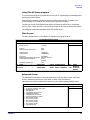
Using The HP Setup program . . . . . . . . . . . . . . . . . . . . . . . . . . . . . . .
Main Screen. . . . . . . . . . . . . . . . . . . . . . . . . . . . . . . . . . . . . . . . . . . . . .
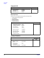
Advanced Screen . . . . . . . . . . . . . . . . . . . . . . . . . . . . . . . . . . . . . . . . . .
Processors, Memory And Cache . . . . . . . . . . . . . . . . . . . . . . . . . . . . . .
Floppy Disk Drives . . . . . . . . . . . . . . . . . . . . . . . . . . . . . . . . . . . . . . . .
4
64
65
65
65
66
66
Contents
IDE Devices . . . . . . . . . . . . . . . . . . . . . . . . . . . . . . . . . . . . . . . . . . . . . .66
IDE Primary Master Device . . . . . . . . . . . . . . . . . . . . . . . . . . . . . . . . .66
Integrated USB Interface . . . . . . . . . . . . . . . . . . . . . . . . . . . . . . . . . . .67
Integrated I/O Ports . . . . . . . . . . . . . . . . . . . . . . . . . . . . . . . . . . . . . . . .67
Integrated Audio Device . . . . . . . . . . . . . . . . . . . . . . . . . . . . . . . . . . . .67
AGP Configuration (Video) . . . . . . . . . . . . . . . . . . . . . . . . . . . . . . . . . .67
PCI Device, Slot #1 . . . . . . . . . . . . . . . . . . . . . . . . . . . . . . . . . . . . . . . . .67
Integrated LAN . . . . . . . . . . . . . . . . . . . . . . . . . . . . . . . . . . . . . . . . . . .68
Security Screen. . . . . . . . . . . . . . . . . . . . . . . . . . . . . . . . . . . . . . . . . . . .68
Hardware Protection . . . . . . . . . . . . . . . . . . . . . . . . . . . . . . . . . . . . . . .68
Boot Screen . . . . . . . . . . . . . . . . . . . . . . . . . . . . . . . . . . . . . . . . . . . . . . .69
Power Screen . . . . . . . . . . . . . . . . . . . . . . . . . . . . . . . . . . . . . . . . . . . . .69
Updating The System BIOS . . . . . . . . . . . . . . . . . . . . . . . . . . . . . . . . . . .70
Restoring BIOS Default Settings . . . . . . . . . . . . . . . . . . . . . . . . . . . . .70
If You Forget The Administrator Password . . . . . . . . . . . . . . . . . . . . .70
Clearing The CMOS . . . . . . . . . . . . . . . . . . . . . . . . . . . . . . . . . . . . . . . .71
Recovering The BIOS (Crisis Mode) . . . . . . . . . . . . . . . . . . . . . . . . . . .71
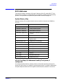
BIOS Addresses . . . . . . . . . . . . . . . . . . . . . . . . . . . . . . . . . . . . . . . . . . . . .73
System Memory Map . . . . . . . . . . . . . . . . . . . . . . . . . . . . . . . . . . . . . . .73
HP I/O Port Map (I/O Addresses Used By The System, if configured) 73
DMA Channel Controllers . . . . . . . . . . . . . . . . . . . . . . . . . . . . . . . . . . .74
4. Tests And Error Messages
MaxiLife Test Sequence And Error Messages . . . . . . . . . . . . . . . . . . . . .78
Basic Pre-boot Diagnostics. . . . . . . . . . . . . . . . . . . . . . . . . . . . . . . . . . .78
Pre-boot Diagnostics Error Codes . . . . . . . . . . . . . . . . . . . . . . . . . . . . .80
POST Sequence And POST Error. . . . . . . . . . . . . . . . . . . . . . . . . . . . . . .81
Operating System Boot Phase . . . . . . . . . . . . . . . . . . . . . . . . . . . . . . . .82
Run-time Errors . . . . . . . . . . . . . . . . . . . . . . . . . . . . . . . . . . . . . . . . . . .82
Main Menu . . . . . . . . . . . . . . . . . . . . . . . . . . . . . . . . . . . . . . . . . . . . . . . . .84
5
Contents
system info. . . . . . . . . . . . . . . . . . . . . . . . . . . . . . . . . . . . . . . . . . . . . . . 84
Boot Steps . . . . . . . . . . . . . . . . . . . . . . . . . . . . . . . . . . . . . . . . . . . . . . . 85
Boot Report . . . . . . . . . . . . . . . . . . . . . . . . . . . . . . . . . . . . . . . . . . . . . . 85
Order In Which POSTs Occur . . . . . . . . . . . . . . . . . . . . . . . . . . . . . . . . . 86
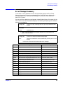
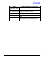
Error Message Summary . . . . . . . . . . . . . . . . . . . . . . . . . . . . . . . . . . . . . 93
5. Hardware Components
Graphics Cards . . . . . . . . . . . . . . . . . . . . . . . . . . . . . . . . . . . . . . . . . . . . . 98
Selecting A Monitor For Your Workstation . . . . . . . . . . . . . . . . . . . . . 98
PCI Cards . . . . . . . . . . . . . . . . . . . . . . . . . . . . . . . . . . . . . . . . . . . . . . . .
HP 10/100 TX PCI LAN Interface . . . . . . . . . . . . . . . . . . . . . . . . . . .
HP 10/100 TX PCI LAN Interface Features . . . . . . . . . . . . . . . . . . .
HP 10/100 TX PCI LAN Interface LED Descriptions . . . . . . . . . . . .
SCSI Adapter Cards . . . . . . . . . . . . . . . . . . . . . . . . . . . . . . . . . . . . . .
100
100
100
101
102
Mass Storage Devices. . . . . . . . . . . . . . . . . . . . . . . . . . . . . . . . . . . . . . .
Flexible Disk Drives . . . . . . . . . . . . . . . . . . . . . . . . . . . . . . . . . . . . . .
Hard Disk Drives . . . . . . . . . . . . . . . . . . . . . . . . . . . . . . . . . . . . . . . .
Optical Drives . . . . . . . . . . . . . . . . . . . . . . . . . . . . . . . . . . . . . . . . . . .
105
105
105
106
Connectors And Sockets. . . . . . . . . . . . . . . . . . . . . . . . . . . . . . . . . . . . .
IDE Drive Connectors. . . . . . . . . . . . . . . . . . . . . . . . . . . . . . . . . . . . .
Battery Pinouts . . . . . . . . . . . . . . . . . . . . . . . . . . . . . . . . . . . . . . . . . .
Additional SCSI LED Connector . . . . . . . . . . . . . . . . . . . . . . . . . . . .
Power Supply Connector (20-pin) And Aux Power Connector . . . . .
Wake On LAN Connector . . . . . . . . . . . . . . . . . . . . . . . . . . . . . . . . . .
Rear Fan Connector . . . . . . . . . . . . . . . . . . . . . . . . . . . . . . . . . . . . . .
PCI Fan Connector (MT only). . . . . . . . . . . . . . . . . . . . . . . . . . . . . . .
internal audio connectors . . . . . . . . . . . . . . . . . . . . . . . . . . . . . . . . . .
Status Panel And Intrusion . . . . . . . . . . . . . . . . . . . . . . . . . . . . . . . .
Hard Disk Drive Temperature . . . . . . . . . . . . . . . . . . . . . . . . . . . . .
109
109
109
109
110
110
110
110
110
111
111
6
Contents
VGA DB15 Connector. . . . . . . . . . . . . . . . . . . . . . . . . . . . . . . . . . . . . .111
LCD Panel. . . . . . . . . . . . . . . . . . . . . . . . . . . . . . . . . . . . . . . . . . . . . . .112
Rear Panel Connectors . . . . . . . . . . . . . . . . . . . . . . . . . . . . . . . . . . . . . .113
Keyboard And Mouse Connectors . . . . . . . . . . . . . . . . . . . . . . . . . . . .113
USB Stacked Connector . . . . . . . . . . . . . . . . . . . . . . . . . . . . . . . . . . . .114
Serial Port Connectors . . . . . . . . . . . . . . . . . . . . . . . . . . . . . . . . . . . . .114
25-pin Parallel Connector . . . . . . . . . . . . . . . . . . . . . . . . . . . . . . . . . .115
MIDI/Joystick Connector . . . . . . . . . . . . . . . . . . . . . . . . . . . . . . . . . . .116
External Audio Jacks . . . . . . . . . . . . . . . . . . . . . . . . . . . . . . . . . . . . . .116
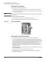
6. Installing Or Replacing Parts And Accessories
Overview . . . . . . . . . . . . . . . . . . . . . . . . . . . . . . . . . . . . . . . . . . . . . . . . .118
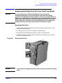
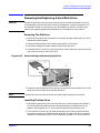
Removing And Replacing The Cover And Front Bezel . . . . . . . . . . . . .119
Removing The Cover . . . . . . . . . . . . . . . . . . . . . . . . . . . . . . . . . . . . . .119
Removing The Front Bezel. . . . . . . . . . . . . . . . . . . . . . . . . . . . . . . . . .120
Replacing The Cover And Front Bezel . . . . . . . . . . . . . . . . . . . . . . . .120
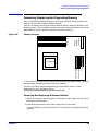
Removing, Replacing And Upgrading Memory . . . . . . . . . . . . . . . . . . .121
Removing And Replacing A Memory Module . . . . . . . . . . . . . . . . . . .121
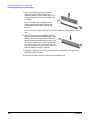
Installing Or Replacing An Accessory Card. . . . . . . . . . . . . . . . . . . . . .123
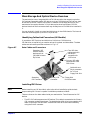
Mass Storage And Optical Device Overview . . . . . . . . . . . . . . . . . . . . .125
Identifying Cables And Connectors (All Models) . . . . . . . . . . . . . . . .125
Installing IDE Drives . . . . . . . . . . . . . . . . . . . . . . . . . . . . . . . . . . . . . .125
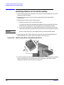
Installing SCSI Drives . . . . . . . . . . . . . . . . . . . . . . . . . . . . . . . . . . . . . .127
Setting SCSI IDs . . . . . . . . . . . . . . . . . . . . . . . . . . . . . . . . . . . . . . . . .128
Verifying Your SCSI Drive . . . . . . . . . . . . . . . . . . . . . . . . . . . . . . . . . .131
additional guide rails . . . . . . . . . . . . . . . . . . . . . . . . . . . . . . . . . . . . . .131
Removing And Replacing A Hard Disk Drive . . . . . . . . . . . . . . . . . . . .133
Removing The Old Drive . . . . . . . . . . . . . . . . . . . . . . . . . . . . . . . . . . .133
Installing The New Drive. . . . . . . . . . . . . . . . . . . . . . . . . . . . . . . . . . .133
7
Contents
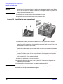
Installing A Second Hard Disk Drive In An Internal Shelf. . . . . . . . . 135
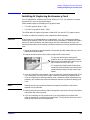
Installing A Device In A Front Access Bay . . . . . . . . . . . . . . . . . . . . . . 136
Completing Mass Storage Device Installation . . . . . . . . . . . . . . . . . . . 138
IDE Drive. . . . . . . . . . . . . . . . . . . . . . . . . . . . . . . . . . . . . . . . . . . . . . . 138
SCSI Drive On SCSI Models . . . . . . . . . . . . . . . . . . . . . . . . . . . . . . . 138
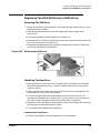
Replacing The CD-ROM Drive (or DVD-drive). . . . . . . . . . . . . . . . . . . 139
Removing The Old Drive . . . . . . . . . . . . . . . . . . . . . . . . . . . . . . . . . . 139
iNstalling The New Drive. . . . . . . . . . . . . . . . . . . . . . . . . . . . . . . . . . 139
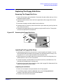
Replacing The Floppy Disk Drive . . . . . . . . . . . . . . . . . . . . . . . . . . . . . 141
Removing The Floppy Disk Drive . . . . . . . . . . . . . . . . . . . . . . . . . . . 141
Installing The Floppy Disk Drive. . . . . . . . . . . . . . . . . . . . . . . . . . . . 141
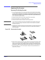
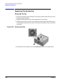
Replacing The Power Supply Unit . . . . . . . . . . . . . . . . . . . . . . . . . . . . 142
Removing The Power Supply Unit . . . . . . . . . . . . . . . . . . . . . . . . . . . 142
Installing The Power Supply Unit . . . . . . . . . . . . . . . . . . . . . . . . . . . 142
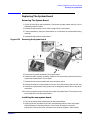
Replacing The Processor . . . . . . . . . . . . . . . . . . . . . . . . . . . . . . . . . . . . 143
Removing The Existing Processor . . . . . . . . . . . . . . . . . . . . . . . . . . . 143
Installing The New Processor. . . . . . . . . . . . . . . . . . . . . . . . . . . . . . . 144
Replacing The System Board . . . . . . . . . . . . . . . . . . . . . . . . . . . . . . . . 145
Removing The System Board . . . . . . . . . . . . . . . . . . . . . . . . . . . . . . . 145
installing the new system board . . . . . . . . . . . . . . . . . . . . . . . . . . . . 145
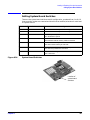
Setting System Board Switches. . . . . . . . . . . . . . . . . . . . . . . . . . . . . . . 147
Replacing The System Fan . . . . . . . . . . . . . . . . . . . . . . . . . . . . . . . . . . 148
Removing The Fan . . . . . . . . . . . . . . . . . . . . . . . . . . . . . . . . . . . . . . . 148
Replacing The Rear Fan . . . . . . . . . . . . . . . . . . . . . . . . . . . . . . . . . . . 149
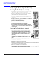
Replacing The Fan And Speaker Assembly . . . . . . . . . . . . . . . . . . . . . 150
Removing The Fan And Speaker Assembly. . . . . . . . . . . . . . . . . . . . 150
Replacing The Fan And Speaker Assembly . . . . . . . . . . . . . . . . . . . . 150
Replacing The Battery . . . . . . . . . . . . . . . . . . . . . . . . . . . . . . . . . . . . . . 151
8
Contents
System Board Connectors . . . . . . . . . . . . . . . . . . . . . . . . . . . . . . . . . . .152
7. Troubleshooting Your Workstation
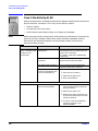
Case 1: No Activity At All . . . . . . . . . . . . . . . . . . . . . . . . . . . . . . . . . . . .156
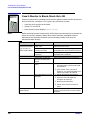
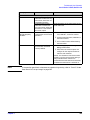
Case 2: Monitor Is Blank, MaxiLife Is OK . . . . . . . . . . . . . . . . . . . . . . .158
Case 3: Boot Fails, Monitor Is Blank,
MaxiLife Displays Error Message . . . . . . . . . . . . . . . . . . . . . . . . . . . . .160
Pre-boot Diagnostics. . . . . . . . . . . . . . . . . . . . . . . . . . . . . . . . . . . . . . .160
Pre-boot Test Errors . . . . . . . . . . . . . . . . . . . . . . . . . . . . . . . . . . . . . . .161
Post Test Errors . . . . . . . . . . . . . . . . . . . . . . . . . . . . . . . . . . . . . . . . . .162
Case 4: Boot Process Fails, Error Message Appears . . . . . . . . . . . . . . .164
Error Message Utility (EMU) . . . . . . . . . . . . . . . . . . . . . . . . . . . . . . .164
Case 5: Screen Goes Blank Or Corrupt Image. . . . . . . . . . . . . . . . . . . .166
Use Or Configuration Problems . . . . . . . . . . . . . . . . . . . . . . . . . . . . . . .167
CMOS Test Error . . . . . . . . . . . . . . . . . . . . . . . . . . . . . . . . . . . . . . . . .168
Keyboard Test Error. . . . . . . . . . . . . . . . . . . . . . . . . . . . . . . . . . . . . . .168
Floppy Disk Drive Test Error . . . . . . . . . . . . . . . . . . . . . . . . . . . . . . .169
hard disk, DVD, CD-RW or CD-ROM test error . . . . . . . . . . . . . . . . .169
Serial Or Parallel Port Test Error . . . . . . . . . . . . . . . . . . . . . . . . . . . .171
Error Message Appears On The MaxiLife LCD During Runtime . . .171
You Cannot Turn Off Your Workstation . . . . . . . . . . . . . . . . . . . . . . .172
You Have Forgotten Your Password . . . . . . . . . . . . . . . . . . . . . . . . . .173
Your Workstation Has A Software Problem . . . . . . . . . . . . . . . . . . . .174
Workstation Clock Does Not Keep Time Correctly. . . . . . . . . . . . . . .174
You Have Problems Using The Euro Symbol . . . . . . . . . . . . . . . . . . .175
Troubleshooting BIOS Problems . . . . . . . . . . . . . . . . . . . . . . . . . . . . . .176
Updating The BIOS . . . . . . . . . . . . . . . . . . . . . . . . . . . . . . . . . . . . . . .176
Restoring BIOS Default Settings . . . . . . . . . . . . . . . . . . . . . . . . . . . .176
Clearing The CMOS . . . . . . . . . . . . . . . . . . . . . . . . . . . . . . . . . . . . . . .176
9
Contents
Recovering The BIOS (crisis mode) . . . . . . . . . . . . . . . . . . . . . . . . . . 177
System Board Switches . . . . . . . . . . . . . . . . . . . . . . . . . . . . . . . . . . . . . 178
Using The HP Setup Program . . . . . . . . . . . . . . . . . . . . . . . . . . . . . . . . 179
First, Turn On Or Restart Your Workstation . . . . . . . . . . . . . . . . . . 179
To Go To The Setup Program . . . . . . . . . . . . . . . . . . . . . . . . . . . . . . . 179
More Troubleshooting For Drives . . . . . . . . . . . . . . . . . . . . . . . . . . . . .
If The Hard Disk Has A Problem . . . . . . . . . . . . . . . . . . . . . . . . . . . .
CD-ROM, DVD or CD-RW Drive Does Not Work . . . . . . . . . . . . . . .
CD-ROM, DVD or CD-RW Drive Is Idle . . . . . . . . . . . . . . . . . . . . . .
DVD drive doesn’t play DVD video . . . . . . . . . . . . . . . . . . . . . . . . . .
CD-ROM, DVD or CD-RW Door Does Not Open . . . . . . . . . . . . . . . .
180
180
180
181
181
181
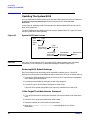
HP e-DiagTools Hardware Diagnostics . . . . . . . . . . . . . . . . . . . . . . . . .
Overview Of e-DiagTools . . . . . . . . . . . . . . . . . . . . . . . . . . . . . . . . . .
running e-DiagTools from the utility partition on your hard disk . .
Running e-DiagTools From A CD-ROM. . . . . . . . . . . . . . . . . . . . . . .
HP e-DiagTools Hardware Tests . . . . . . . . . . . . . . . . . . . . . . . . . . . .
for more information . . . . . . . . . . . . . . . . . . . . . . . . . . . . . . . . . . . . . .
182
182
182
183
184
184
Recovering Hard Disk Drive Contents (Windows only) . . . . . . . . . . . .
Overview . . . . . . . . . . . . . . . . . . . . . . . . . . . . . . . . . . . . . . . . . . . . . . .
General Instructions . . . . . . . . . . . . . . . . . . . . . . . . . . . . . . . . . . . . . .
Recovery Process . . . . . . . . . . . . . . . . . . . . . . . . . . . . . . . . . . . . . . . . .
Recovering Preloaded Drivers . . . . . . . . . . . . . . . . . . . . . . . . . . . . . .
Changing The Hard Disk . . . . . . . . . . . . . . . . . . . . . . . . . . . . . . . . . .
186
186
186
186
187
187
Other Sources Of Information . . . . . . . . . . . . . . . . . . . . . . . . . . . . . . . . 188
Online Support For Troubleshooting . . . . . . . . . . . . . . . . . . . . . . . . . 188
Documentation Set Overview. . . . . . . . . . . . . . . . . . . . . . . . . . . . . . . 188
Hewlett-Packard Support And Information Services. . . . . . . . . . . . . . 189
collecting information before contacting hp support. . . . . . . . . . . . . 189
10
Contents
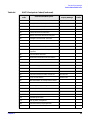
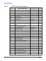
A. x2100 Service Information
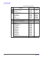
Parts and Part Numbers . . . . . . . . . . . . . . . . . . . . . . . . . . . . . . . . . . . . . . .2
11
Contents
12
1
System Overview
This chapter provides detailed system specifications for the HP Workstation x2100:
Chapter 1
•
Introduces the system’s internal and external features
•
Lists the system’s specifications and characteristic data
•
Provides a summary of the available documentation
13
System Overview
Workstation Description
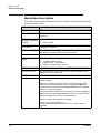
Workstation Description
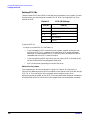
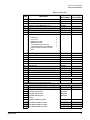
The HP Workstation x2100 is based on the ATX form factor. The following table provides
an overview of the system.
Feature
Description
System Board
Dimensions: 12 in. X 9.6 in. in an Extended-ATX (E-ATX) package
Processor
Intel Pentium 4 processor
Socket 423
Cache Memory
(integrated in processor
package)
•
Level 1: 16KB code, 16KB data
•
Level 2: 256KB
Internal Processor
Clock Speed
1.7GHz, 1.9GHz, 2.2 GHz and higher speeds with a quad-pumped
100MHz Front Side Bus
Chipset
Intel I850 chipset, including Memory Controller Hub (MCH) Host Bridge,
Input/Output Controller Hub (ICH) for I/O subsystem
Super I/O Chip
NS 87364
Basic I/O System
(BIOS)
Based on Phoenix core, including:
•
•
•
4 megabits of flash memory
Support for PCI 2.2 specification
Support for RIMM memory modules
Firmware - BIOS
Flash EEPROM: Intel’s firmware hub concept
HP MaxiLife Utility
Hardware-monitoring utility that monitors system components via the
SMBus and an LCD status panel
Operating System
All models come preloaded with a Windows OS.
Main Memory
Two pairs of RIMM sockets, supporting two or four PC800 RDRAM
memory modules
Each pair of memory sockets must contain identical memory modules
(identical in size, speed, and type). That is, sockets A1 and B1 must
contain identical modules, and sockets A2 and B2 must contain identical
modules (or continuity modules).
If only two RDRAM modules are installed, use the sockets marked A1 and
B1. The other two sockets (A2 and B2) must contain continuity modules.
Models are supplied with non-ECC RDRAM modules.
Both ECC and non-ECC modules are available.
The HP PC Accessories Web site, at
www.hp.com/desktops/products/accessories, lists up-to-date memory
upgrades.
14
Chapter 1
System Overview
Workstation Description
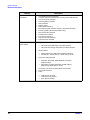
Feature
Mass Storage
Description
Seven shelves, supporting:
•
Two front-access, third-height 3 1/2-inch drives (one for the floppy
disk drive and one free) (1-inch height)
•
Three front-access, half-height, 5 1/4-inch drives (1-inch height); you
can use an adapter tray (available as an accessory) to install two 3
1/2-inch hard disk drives in one of the 5 1/4-inch shelves.
•
Two internal 3 1/2-inch hard disk drives (1-inch height)
SCSI Controller
Adaptec Ultra 160 SCSI PCI card (optional).
IDE Controller
All models include an integrated Ultra ATA-100 controller that supports
as many as four IDE devices.
Graphics Controllers
•
nVIDIA Quadro2 MXR with TwinView or nVIDIA Quadro Pro
nVIDIA Quadro2 Ex
ATI FireGL 8800
Accessory Card Slots
•
Matrox Millennium G450-Dual monitor AGP graphics controller with
16MB SGRAM graphics memory (maximum configuration)
•
ATI FireGL2 or GL4 3D Graphics Card
One AGP Pro Universal 4X 32-bit slot supporting:
•
•
1.5V AGP cards (£25W)
1.5V AGP Pro Cards (£50W)
The system doesn’t support high-power (i.e., greater than 50W) AGP Pro
and 3.3V AGP cards.
Five 32-bit 33MHz Peripheral Component Interconnect (PCI) slots,
supporting all bridges and multifunction PCI devices. All five PCI slots
comply with PCI Specification 2.2.
•
•
Chapter 1
PCI slot 5 contains a LAN interface board.
PCI slot 4 is for a SCSI interface board (some models only).
LAN Card
Lan is now integrated onto the system board. All x2100 models come with
an HP 10/100BT PCI Ethernet Adapter LAN card supporting Wake-On
LAN 9WOL) and PCI Specification 2.2.
Optical Drives
Models include one or two of the following IDE drives: CD-ROM, CD-RW,
or DVD-ROM.
Audio
CrystalClear CS4299 Audio Codec 97 version 2.1 is integrated on the
system board.
15
System Overview
Workstation Description
Feature
Description
System Board
Connectors
•
•
•
•
•
•
•
•
•
•
•
•
•
•
One flexible disk drive connector
Two ATA-100 IDE connectors (for as many as four IDE devices)
One CD-IN audio connector
Internal speaker connector
WOL connector
Battery socket
Status panel connector
Main power supply connector and ATX 12V power connector
Auxiliary power connector (MT models only)
Main chassis fan connector
Processor fan connector
PCI card fan connector
Chassis intrusion connector
Thermal sensor connector
Rear Connectors
(color coded)
•
Keyboard/Mouse
— HP enhanced keyboard with mini-DIN connector
— HP enhanced scrolling mouse with mini-DIN connector
•
25-pin parallel
— Mode: Centronics or bidirectional modes (ECP/EPP)
— Parallel port: 1 (378h, IRQ 7), 2 (278h, IRQ 5), or Off
•
9-pin serial (two, buffered)
— Standard: Two UART 16550 buffered serial ports
(both RS-232-C).
— Serial Ports A and B: 2F8h (IRQ 3), 2E8h (IRQ 3),
3F8h (IRQ 4), 3E8h (IRQ 4), or Off
•
•
(if one port uses 2xxh, the other port must use 3xxh).
Dual USB connectors
Audio
— LINE IN jack (3.5mm)
— LINE OUT jack (3.5mm)
— MIC IN jack (3.5mm)
16
Chapter 1
System Overview
Internal And External Components
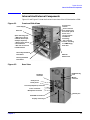
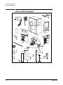
Internal And External Components
Figure 1-1 and Figure 1-2 show the front and rear views of the HP Workstation x2100.
Figure 1-1
Front and Side Views
Front access
shelves:
- three 5 1/4-inch
drive shelves (can
be used for optical
drives or a 3
1/2-inch tray kit–
available as
accessory)
- two 3 1/2-inch
shelves, including
a 1.44MB floppy
disk drive
Power Supply
Main Fan
Spare mounting rails:
- Wide green rails for
5.25-inch devices (for
example, Zip drive)
- Narrow green rails for
3.5-inch devices
- Blue rails for 3.5-inch
hard disk drives
Secondary Hard Disk
Drive Shelf
MaxiLife
Status Panel
Primary Hard Disk
Drive Shelf
Figure 1-2
Rear View
Keyboard
connector
Serial port A
HP Master Key
Lock
Mouse
connector
Serial port B
Line Out (headphone) connector
Line In connector
Microphone connector
Dual USB connectors
Parallel port
Display connector
Chapter 1
17
System Overview
Internal Features
Internal Features
The core architecture of the HP Workstation x2100 consists of:
•
Memory Controller Hub (MCH)
•
Input/Output Controller Hub (ICH)
•
Host bus
The HP Workstation x2100 supports a Pentium 4 processor. For information about this
processor, see page 58.
For information about...
18
Refer to...
System board components
Chapter 2
HP BIOS routines
Chapter 3
Tests and error messages including Power On Self Test
(POST) routines
Chapter 4
Graphics, network and SCSI devices, and mass storage
devices
Chapter 5
Accessories Installation and Parts Replacement
Chapter 6
Use or configuration problems
Chapter 7
Troubleshooting and Recovery
Chapter 7
Contacting support
Chapter 7
Chapter 1
System Overview
Front Panel
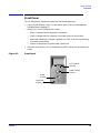
Front Panel
The HP Workstation x2100’s front panel has the following features:
•
Liquid Crystal Display (LCD). For information about LCD error messages and
available menus, see page 77.
•
On/Off LED. The LED displays four states:
— Blank: Indicates that the computer is turned off.
— Green: Indicates that the computer is turned on and running correctly.
— Red (fixed or flashing): Indicates a preboot or a POST error that is preventing
the system from booting.
— Amber: Displayed during system reset, system lock.
•
Figure 1-3
Hard disk drive activity LED. Activated during POST and during hard disk drive
access.
Front Panel
LCD Control
Buttons
Power On/Off
Button
Reset
Button
Hard Disk
Activity Light
Chapter 1
19
System Overview
Specifications And Characteristics
Specifications And Characteristics
Physical Characteristics
System Processing Unit
Weight: (Standard
configuration as shipped,
excluding keyboard and
display)
14.4 kilograms (31.68 pounds)
Dimensions
47.0cm max. (D) X 21.0cm (W) X 49.0cm (H)
(18.50 inches X 8.26 inches X 19.29 inches)
Footprint
0.09 square meters (1.06 square feet)
Electrical Specifications
Parameter
Input voltage
(Switch select)
Input current
(max)
Total Rating
Peak
(15
secs.)
Maximum
per PCI
Slots
32-bit
33MHz
Maximum for AGP Slota
Standard
Connector
Extension
Total
100-127
V VAC
200-250
V VAC
—
—
—
—
—
5.5 A
2.5 A
—
—
—
—
—
—
—
—
Input frequency
50 to 60 Hz
—
—
Available power
492 W
—
100W for PCI slots and AGP Pro slot
Max current at
+12 V
15 A
15 A
0.5 A
1A
4.2 A
5.2 A
Max current at
-12 V
0.8 A
—
0.1 A
—
—
—
Max current at
+3.3V
28 A
—
7.6 A
6A
7.6 A
13.6 A
Vddqb
—
—
—
2A
Max current at
+5V
30 A
—
5A
2A
Max current at
-5V
0.0 A
—
—
Max current at
+5V stdby
combined with
3.3V stdby
2A
—
1.875 A total on 3.3V stdby
—
—
—
a. The system can draw a maximum of 50W from the AGP Pro slot. The standard part
of the AGP Pro connector supplies 25W (max.), plus 25W from the connector
extension (25W + 25W = 50W). For information about the AGP Pro Universal slot,
see page 33.
b. Only for I/O buffers.
20
Chapter 1
System Overview
Specifications And Characteristics
If an overload triggers the power supply’s overload protection, all power is immediately
cut. To reset the power supply unit:
1. Disconnect the power cord.
2. Determine what caused the overload, and fix the problem.
3. Reconnect the power cord, and reboot the workstation.
If an overload occurs twice, then there is an undetected short circuit somewhere.
When you use the front panel's power button to turn off the workstation, power
consumption falls below the low power consumption (refer to the table on page 21), but
doesn't reach zero. This on/off feature extends the power supply's lifetime. To reach zero
power consumption in “off ” mode, either unplug the workstation or use a power block
with a switch.
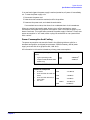
Power Consumption And Cooling
The power consumption and acoustics listed in the following table are valid for a
standard configuration as shipped (one processor, 256MB of memory, 492 W power
supply, one hard disk drive, graphics card, LAN card).
All information in this section is based on primary power consumptions.
Power consumption (approximate
values)
230V/50Hz and 115V/60Hz
•
Typical operating mode
•
Suspend mode (Windows 2000
models only)
70W
<4W
- 238.8Btu/ha
- 13.6Btu/h
a. 1W = 3.4121Btu/h
Additional Component
•
•
•
•
Processor
SCSI hard disk drive with I/O
access
SCSI hard disk without I/O
access (idle)
PCI card
50W
- 170.6Btu/h
23W
- 78.4Btu/h
16W
- 54.5Btu/h
10W to
36W
Chapter 1
- 64.1Btu/h to
122.8Btu/h
21
System Overview
Specifications And Characteristics
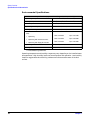
Environmental Specifications
Environmental Specifications (System Processing Unit with Hard Disk)
Operating Temperature
+10 ˚C to +35 ˚C (+40 ˚F to +95 ˚F).
Storage Temperature
-40 ˚C to +70˚C (-40 ˚F to +158 ˚F).
Over-Temperature Shutdown
+50˚C (+122˚F)
Operating Humidity
15% to 80% (relative).a
Storage Humidity
8% to 85% (relative).1
Acoustic noise emission (as defined in ISO
7779):
Sound Power
Sound Pressure
LwA <= 40.5dB
LpA <= 25.7dB
LwA <= 41.4dB
LpA <= 26.5dB
LwA <= 43.2dB
LpA <= 30.0dB
•
Operating
•
Operating with hard disk access
•
Operating with floppy disk access
Operating Altitude
10,000ft (3100m) max
Storage Altitude
15,000ft (4600m) max
a. noncondensing conditions.
Operating temperature and humidity ranges may vary depending on the installed mass
storage devices. High humidity levels can cause improper disk operation. Low humidity
levels can aggravate static electricity problems and cause excessive wear of the disk
surface.
22
Chapter 1
System Overview
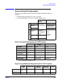
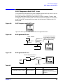
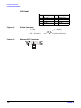
Power Saving And Ergonometry
Power Saving And Ergonometry
Depending on the operating system, the following power-management types are
available:
•
No sleeping state: Windows NT 4.0 (Full On and Off).
•
ACPI: Windows 2000 or XP (Full On, Standby, Hibernate, Off).
Windows
2000/XP
Windows NT 4.0
Full On
A
P
M
Supported
Not Supported
by Windows 2000
Suspend
Not Supported by
Windows NT 4.0
Off
A
C
P
I
Supported
Standby (S1
or S3)
Supported
(implemented as
S3, Suspend to
RAM)
Hibernate
(S4)
Supported
Off (S5)
Supported
APM
only
Operating
System
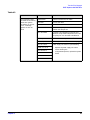
Power Saving And Ergonometry For APM Systems
Suspenda
Full On
Off
Processor
Normal speed
Halted
Halted
Display
On
Blanked, <5W (typ)
Blanked, <5W (typ)
Hard disk drive
Normal speed
Halted
Halted
Power
consumption
Supports up to
320W
<40W (230V, 50Hz)
<21W (115V, 60Hz)
(plugged in but turned
off) <5W (average)
Resume events
Keyboard, network
(RWU), modem, USB
Power button or RPO
Resume delay
A few seconds
Boot delay
a. Not supported by Windows NT 4.0.
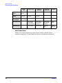
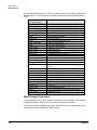
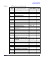
Power Saving Modes And Resume Events For ACPI Systems
Full On
(S0)
Chapter 1
Suspend (S1)
Suspend to
RAM (S3)
Suspend to
Disk (S4)
Off (S5)
Processor
Normal
speed
Halted
Off
Off
Off
Display
On
Blanked
Off
Off
Off
23
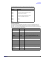
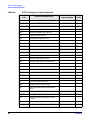
System Overview
Power Saving And Ergonometry
Full On
(S0)
Suspend (S1)
Suspend to
RAM (S3)
Suspend to
Disk (S4)
Off (S5)
Hard Disk
Drive
Normal
speed
Halted
Off
Off
Off
Active Power
Planes
VCC
VCCAux
VCC
VCCAux
Memory
VCCAux
VCCAux
VCCAux
Power
Consumption
Supports
up to 492W
<40W
<10W
<10W
<10W
Resume Events
Power button,
LAN, Modem,
USB, Scheduler
Power button,
LAN, Modem,
Scheduler
Power button,
LAN, Modem,
Scheduler
Power
button
Resume Delay
Instantaneous
Instantaneous
BIOS boot
delay
Regular
boot delay
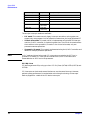
Soft Power Down
When you shut down the operating system, the environment is cleared, and the
computer is powered off. The Soft Power Down utility is available with Windows NT.
24
Chapter 1
System Overview
Documentation
Documentation
The following table lists the documentation available for the HP Workstation x2100.
Only selected publications are in hard-copy format. Most are available as PDF files from
the HP Web site.
Title
Available at
HP Web site
Hard-copy?
HP Workstation x2100
Getting Started Guide
PDF file
A8030-90001
HP Workstation x21000
Technical Reference And
Troubleshooting Guide
PDF file
No
Access HP World Wide Web Site
Additional online support documentation, BIOS upgrades, and drivers are available
from HP’s Web site at http://www.hp.com/go/workstationsupport.
After accessing the site, select HP Workstation x2100.
Chapter 1
25
System Overview
Documentation
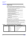
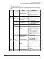
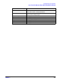
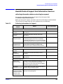
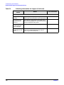
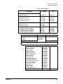
Where To Find The Information
The table below summarizes information provided in the HP Workstation x2100
documentation set.
Getting
Started
Guide
Technical
Reference/Troubles
hooting Guidea
Service
Handbook
Introducing the Workstation
Product features
Minimal
Key features.
Product model
numbers
Exploded view.
Parts list.
Product range.
Environmental
Setting up the
PC. Working
in Comfort.
Complete listing.
Safety warnings
Safety.
Electrical,
multimedia, safety,
unpacking, removing,
and replacing cover.
Finding on-line
information
HP Web sites.
HP Web sites.
Technical
information
Basic details.
Advanced.
Formal documents
Certificate of
Conformity.
Software
License
agreement.
Using the Workstation
Connecting devices
and turning on
Rear panel
connectors,
starting and
stopping.
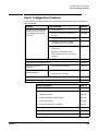
BIOS
Basic details.
Advanced.
Fields and their
options within
Setup
Basic details.
Viewing Setup
screen, using,
passwords
Complete list.
Manageability
Power
management,
Software and
drivers.
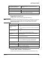
Upgrading the Workstation
26
Opening the PC
Full description.
Supported
accessories
Full description
Full PN details
Chapter 1
System Overview
Documentation
Getting
Started
Guide
Technical
Reference/Troubles
hooting Guidea
Service
Handbook
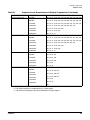
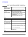
Installing
accessories
Processor(s), memory,
accessory boards,
mass storage devices.,
fans, power supply,
system board, battery
Configuring
devices
Installing devices.
System board
Installing and
removing, connectors
and switch settings.
Chip-set details.
Jumpers,
switches and
connectors.
Advanced. MaxiLife,
hardware diagnoses
and suggested
solutions.
Service notes.
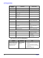
Repairing the Workstation
Troubleshooting
Basic.
Power-On Self-Test
routines (POST)
Diagnostic utility
Error codes,
messages,
EMU and suggestions
for corrective action.
Order of tests.
e-DiagTools,
CD-ROM
recovery.
HP e-DiagTools,
CD-ROM recovery
Technical Details.
Peripheral Devices
Audio Accessories
Refer to online
version of Audio
User’s Guide for
information about
setting up and
configuring audio
accessories.
LAN Accessories
Refer to online
version (preloaded on
hard disk) of LAN
Administrator’s
Guide for information
on setting up and
configuring LAN
cards and systems.
a. For address, “Access HP World Wide Web Site” on page 25.
Chapter 1
27
System Overview
Documentation
28
Chapter 1
2
Chapter 2
System Board
29
System Board
System Board Description
System Board Description
This chapter describes the components of the system board including:
•
Memory Controller Hub (MCH)
•
Input/Output Controller Hub (ICH2)
•
FirmWare Hub (FWH)
•
System Bus
Figure 2-1 shows the HP Workstation x2100 system board in detail.
Figure 2-1
HP Workstation x2100 System Board
cm es
.4 nch
24 .6 i
9
30
cm es
.5
30 inch
12
Chapter 2
System Board
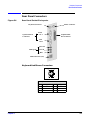
System Board Description
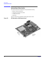
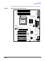
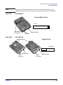
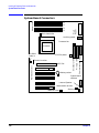
Figure 2-2 shows where the different chips and connectors reside on the system board.
System Board Chips and Connectors
Main power
supply
B2
B1
Memory slots
Figure 2-2
A2
A1
Main chassis fan
Auxiliary power
(MT models only)
MCH
Processor fan
AGP slot
PCI slots
ICH2
Battery socket
Thermal sensor
Chassis intrusion
Primary IDE
ATX12V
power
Secondary IDE
CD-ROM
audio in
Floppy
Pentium IV
processor
(socket 423)
System board
switches
HP MaxiLife
Internal speaker
Wake On LAN
PCI card fan
Status panel
Chapter 2
31
System Board
System Board Description
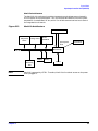
Architectural View
Intel Pentium IV
processor
Socket 423
Address (36)
Control
Data (64)
1.5V
AGP
PRO
Connector
AGP 4x Bus
(133MHz
(1GB/sec data
transfer rate)
100 MHz two-way
System Bus (Data
Bus runs at 4 x
100 MHz, 3.2 GB/s
transfer rate)
850
Memory
Controller Hub
(MCH)
82850
Dual Rambus Channel
3.2GB/s at
400MHz data
transfer rate
HUB LINK 8
(266 MB/s data transfer
rate)
Four
onboard
RIMM
sockets
supporting
RDRAM
memory.
I/O
ControllerHub2
Hub
I/O
Controller
(ICH) 82801AA
(ICH2)
82801BA
2 IDE
connectors
4 USB
connectors
Parallel
and serial
ports
IDE
controller
4 x USB
controller
USB
LPC
bridge
AC’97
audio
controller
SM Bus
controller
FirmWare
Hub (FWH)
82802AA
PCI Bus (32-bit, 33 MHz)
133 MB/s data transfer rate
Slot 1 - 32-bit/33MHz
Slot 2- 32-bit/33MHz
Slot 3 - 32-bit/33MHz
Super
LPC / FWH Link
I/O
NS 87364
Slot 4 - 32-bit/33MHz
LAN
Interface
Serial
EEPROM
32
PCI bridge
SMBus
PS2
Keyboard,
PS2 mouse,
and floppy
ATA/100 2
channels
Slot 5 - 32-bit/33MHz
MaxiLife
monitoring chip
Fans
LCD
status
panel
Chapter 2
System Board
Accessory Board Slots
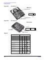
Accessory Board Slots
Figure 2-3 shows the position of the accessory board slots on the system board.
Figure 2-3
Accessory Board Slots
One 1.5V AGP slot
PCI Slot 1
PCI Slot 2
Five 32-bit 33
MHz PCI slots
PCI Slot 3
PCI Slot 4
PCI Slot 5
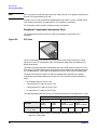
Accelerated Graphics Port Slot
The HP Workstation x2100 has one Accelerated Graphics Port (AGP) graphics slot.
Figure 2-4
AGP Slot
The AGP Pro 1.5V slot provides graphics performance for high-end graphics cards,
combining AGP 4X bandwidth (data transfer rates as fast as 1056MB/sec) with the
ability to accept high-end graphics cards drawing up that draw as much as 110W of
power.
To accommodate AGP Pro cards, the AGP PRO slot connector is wider than the standard
AGP 4X connector. To meet the increased power requirements of AGP Pro graphics
cards, additional pins are present at both ends of the connector.
An AGP Pro card may draw power either from the existing part of the AGP Pro
connector, the extended part, or a combination of the two. In all cases, the maximum
power that an AGP Pro card may draw is limited to 110W in the workstation models.
Power on the existing part of the connector is delivered on 5.0V and 3.3V rails. Power on
the extension is delivered on the 12V and 3.3V rails.
You can use either standard AGP graphics cards or AGP Pro graphics cards that draw
less than 50W of power. (Below 25W, you can use a standard AGP connector.) Power is
provided through 3.3V, 5V, or 12V power rails.
Chapter 2
33
System Board
Accessory Board Slots
NOTE
AGP Pro graphics cards that draw more than 50W and AGP 3.3V graphics cards cannot
be used in the workstation’s AGP slot.
The AGP Pro 1.5V slot is backward compatible with both AGP 1x and 2.x modes (using
1.5V signalling) and AGP 4x mode (where 1.5V signalling is necessary).
For information about the AGP interface and bus, see page 41.
Peripheral Component Interconnect Slots
The system board contains five 32-bit, 33MHz Component Interconnect (PCI)
connectors.
Figure 2-5
PCI Slots
The PCI slots accept 3.3V and 5V PCI 32-bit 33MHz cards, and Universal PCI cards
(which are 3.3V or 5V compatible). Refer to the table on page 34 for the different PCI
board installations.
The maximum supported power consumption per slot is 25W, either from the 5V or the
3.3V supply. The power consumption must comply with the electrical specifications of the
PCI 2.2 specification. Total power consumption for the PCI slots must not exceed 60W.
The power consumption of each PCI board is automatically reported to the system
through the two presence-detect pins on each PCI slot. These pins code the following
cases:
•
No accessory board in the PCI slot
•
7W maximum PCI board in the PCI slot
•
15W maximum PCI board in the PCI slot
•
25 maximum PCI board in the PCI slot
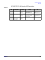
The following table shows the various PCI board installations for the different PCI slots:
PCI Card
3.3V and 5V
Universal (3.3V or 5V compatible)
PCI Slot
32-bit/
33MHz
64-bit/
33MHz
32-bit/
33MHz or 66MHz
64-bit/
33MHz or 66MHz
Slots 1, 2, 3, 4, and 5
5V, 32-bit/33MHz
yes
yesa
yes
yes
yes
yesb
a. You can install a 64-bit card in a 32-bit slot. However, this card will only
operate in 32-bit mode.
34
Chapter 2
System Board
Accessory Board Slots
b. You can install a 66Mhz card in a 33MHz slot. However, this card will only
operate in 33MHz mode.
The system board and BIOS support the PCI 2.2 specification. This specification
supports PCI-to-PCI bridges and multifunction PCI devices, and each of the five PCI
slots have master capabilities.
The PCI slots are connected to the ICH2 PCI 32-bit 33MHz bus.
Chapter 2
35
System Board
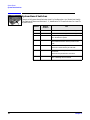
System Board Switches
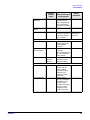
System Board Switches
There Are 10 System Board Switches Used For Configuration. You Should Not Modify
The Settings Of Reserved Switches 1 - 5; Modification Of These Switches Can Lead To
System Failure.
Switch
36
Default
Position
Use
1-4
OFF
Reserved. Do not change default settings.
5
ON
Reserved. Do not change default setting.
6
ON
Enables keyboard power-on.
OFF disables this option.
7
OFF
Enables normal modes.
ON enables the BIOS recovery mode at next
boot.
8
OFF
Retains CMOS memory.
ON clears CMOS memory at next boot.
9
OFF
Enables User and System Administrator
passwords.
ON clears the passwords at next boot.
10
OFF
Chassis type
OFF = desktop, ON= minitower
Chapter 2
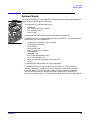
System Board
System Chipset
System Chipset
The Intel I850 chipset is a high-integration chipset designed for graphics/multimedia PC
platforms and is comprised of the following:
MCH
•
The 82850 MCH is a bridge between the:
—
—
—
—
ICH2
System bus
Dual Rambus bus (main memory)
AGP 4x (graphic) bus
Hub link 8-bit
For detailed information about the MCH chip feature, see page 38.
•
The 82801BA ICH2 is a bridge between the 32-bit, 33MHz PCI bus and the SMBus.
Additionally, the ICH2 supports the:
—
—
—
—
—
—
—
—
—
—
—
integrated IDE controller (Ultra ATA/100)
enhanced DMA controller
USB controller
interrupt controller
Low Pin Count (LPC) interface
FWH interface
Integrated LAN
ACPI Power Management Logic
AC’97 2.1 Compliant Link
Alert-On-LAN (AOL) and Real Time Clock (RTC)
CMOS
For detailed information about the ICH2, see page 44.
•
Chapter 2
The 82802AB FWH stores system BIOS and SCSI BIOS (i.e., the nonvolatile
memory component). In addition, the FWH contains an Intel Random Number
Generator (RNG). The RNG provides random numbers to enable fundamental
security building blocks for stronger encryption, digital signing, and security
protocols for the workstation. For detailed information about the FWH, see page 56.
37
System Board
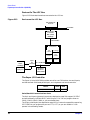
Memory Controller Hub (82850)
Memory Controller Hub (82850)
The MCH host bridge/controller is contained in a 615-pin Organic Land Grid Array
(OLGA) package and is the bridge between the system bus, Dual Rambus bus (main
memory), AGP 4x (graphic), and Hub Link 8-bit.
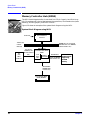
Figure 2-6 shows an example of the system block diagram using the MCH.
Figure 2-6
System Block Diagram using MCH
Socket 423
Intel Pentium IV
Processor
Address (36)
Control
100MHz two-way system bus
(Data Bus runs at 4 x 100MHz,
3.2GB/s transfer rate)
Data (64)
1.5V
AGP
PRO
connector
AGP 4x Bus
133MHz (1 GB
MB/s data transfer
rate)
I850 Memory
Controller Hub (MCH)
82850
AGP
Interface
Memory
Controller
Dual Rambus
3.2GB/s at 400MHz
data transfer rate
Four onboard
RIMM sockets
supporting
RDRAM
memory
HUB LINK 8
(266MB/s data
transfer rate)
I/O Controller Hub2
(ICH2) 82801BA
38
Chapter 2
System Board
Memory Controller Hub (82850)
The following table shows the features that the MCH host bridge/controller offers.
Feature
•
Processor/system bus:
Feature
•
— Supports Pentium IV processor at
Accelerated Graphics Port (AGP) interface:
— Single 1.5V AGP Pro connector
100MHz system bus frequency (400MHz
data bus)
— AGP 2.0 compliant, including AGP 4x
data transfers and 2x/4x Fast Write
protocol
— Provides an eight-deep In-Order Queue
that supports as many as eight
outstanding transaction requests on the
system bus
— AGP 1.5V connector support with 1.5V
signalling only
— AGP PIPE# or SBA initiated accesses to
— Desktop optimized AGTL+ bus driver
DRAM is not snooped
technology with integrated AGTL +
termination resistors
— AGP FRAME initiated accesses to
DRAM are snooped
(snooper identifies that data is coherent
in cache memory)
— Support for 32-bit system bus address
— Hierarchical PCI configuration
mechanism
— Delayed transaction support for
AGP-to-DRAM reads that cannot be
serviced immediately
•
Memory Controller
Direct Rambus:
•
As many as 64 Direct Rambus devices
•
•
Dual-channel maximum memory array size
is:
Dual Direct Rambus Channels operating in
lock-step (both channels must be populated
with a memory module).
Supporting 300MHz or 400MHz
•
RDRAM 128Mbit and 256Mbit devices
•
Minimum upgrade increment of 32MB using
128Mbit DRAM technology
— 1GB using 128Mbit DRAM technology
— 2GB using 256Mbit DRAM technology
•
As many as eight simultaneous open pages:
— 1KB page size support for 128Mbit and
256Mbit RDRAM devices
— 2KB page size support for 256Mbit
RDRAM devices
•
Hub Link 8-bit interface to ICH2:
— High-speed interconnect between the
MCH and ICH2 (266MB/sec)
Chapter 2
39
System Board
Memory Controller Hub (82850)
Feature
•
Power management:
Feature
•
— SMRAM space remapping to A0000h -
Arbitration:
— Distributed arbitration model for
BFFFFh (128KB).
concurrency support
— Extended SMRAM space above 256MB,
— Concurrent operations of system, hub
additional 128KB, 256KB, 512KB, 1MB
TSEG from top of memory, cacheable
(cacheability controlled by processor)
interface, AGP, and memory buses
supported through a dedicated
arbitration and data-buffering logic
— ACPI 1.0 compliant power management
— APM 1.2 compliant power management
•
615 OLGA MCH package
•
I/O device support:
— I/O Controller Hub (ICH2)
MCH Overview
The MCH provides the processor interface, memory interface, AGP interface and hub
interface in an Intel 850 chipset platform. The MCH supports two channels of Direct
RDRAM operating in lock-step. It also supports 4x AGP data transfers and 2x/4x AGP
fast writes. The primary host interface enhancements include:
•
Source synchronous double pumped address
•
Source synchronous quad pumped data
•
System bus interrupt delivery
The MCH supports a 64B cache line size. One processor is supported at a system bus
frequency of 100 MHz (400 MHz Data Bus). It supports 32-bit host addresses, letting the
processor address the entire 4GB space of the MCH’s memory address space. The MCH
also provides an eight-deep In-Order Queue that supports as many as eight outstanding
pipelined address requests on the host bus.
Host-initiated I/O signals are subtractively decoded to the hub interface. Host-initiated
memory cycles are positively decoded to AGP or RDRAM and are again subtractively
decoded to the hub interface.
AGP semantic memory accesses initiated from AGP to DRAM are not snooped on the
host bus. Memory accesses initiated from AGP using PCI semantics and accesses from
the hub interface to DRAM are snooped on the system bus. Memory access whose
addresses lie within the AGP aperture are translated using the AGP address translation
table, regardless of the originating interface.
Accelerated Graphics Port (AGP) Bus Interface
A controller for the AGP Pro 1.5V slot is integrated in the MCH. The AGP interface
supports 1x/2x/4x AGP signaling and 2x/4x fast writes. AGP semantic cycles to the
DRAM are not snooped on the host bus. PCI semantic cycles to DRAM are snooped on
the host bus. The MCH supports PIPE# or SBA{7.0} AGP address mechanisms, but not
both simultaneously. Either the PIPE# or the SBA{7.0] mechanism must be selected
during system initialization. Both upstream and downstream addressing is limited to
40
Chapter 2
System Board
Memory Controller Hub (82850)
32-bit for AGP and AGP/PCI transactions. The MCH contains a 32-deep AGP Requests
queue. High priority accesses are supported. All accesses from the AGP interface that
fall within the graphic aperture address range pass through an address translation
mechanism with a fully associative 20 entry TLB. Accesses between AGP and the hub
interface are limited to memory writes originating from the hub interface for the AGP
bus.
The AGP interface is clocked from a dedicated 66 MHz clock (661N). The
AGP-to-host/core interface is asynchronous. The AGP buffers operate only in 1.5V mode.
They are not 3.3V safe.
Hub Interface
The 8-bit hub interface connects the MCH to the ICH2. Most communications between
the MCH and the ICH2 occur over this interface. The hub interface runs at 66 MHz/266
MB/s.
The hub interface’s supported traffic types include: hub interface-to -AGP memory
writes, hub interface-to-DRAM, processor-to-hub interface, messaging (MSI interrupt
messages, power management state change, MI, SCI, and SERR error indication). It is
assumed that the hub interface is always connected to an ICH2.
RDRAM Interface
The MCH directly supports two channels of Direct RDRAM memory operating in
lock-step using RSL technology. These channels run at 300 MHz and 400MHz and
support 128 Mb and 256 Mb technology RDRAM Direct devices. These 128 Mb and 256
Mb RDRAMs use page sizes of 1 Kb, while 256 Mb devices may also be configured to use
2 Kb pages. A maximum of 64 RDRAM devices are supported on the paired channels
without external logic (128Mbit technology implies 1GB maximum in 32MB increments,
whereas 256Mbit technology implies 2GB maximum in 64MB increments).
The MCH also provides optional ECC error checking for RDRAM data integrity. During
DRAM writes, ECC is generated on a QWord (64-bit) basis. During DRAM reads, and the
read of the data that underlies partial writes, the MCH supports detection of single-bit
and multiple-bit errors, and will correct single-bit errors when correction is enabled.
RDRAM Thermal Management
The relatively high power dissipation needs of RDRAM necessitate a MCH mechanism
capable of putting a number of memory devices into a power-saving mode to keep an
inadequately cooled system from overheating. RDRAM devices may be in one of three
power-management states: active, standby or “nap.” The MCH implements the RDRAM
nap mode.
Two queues are used in the MCH to control power consumption: the A queue contains
references to device pairs that are currently in the active mode while the B queue
contains references to devices that are in the standby mode. This means that all devices
that are in neither queue are in standby or napping. The A queue can hold from 1 to 8
device pairs, while the B queue can be configured to contain between 1 and 16 device
pairs. This allows power consumption to be tuned.
The MCH also implements a mode in which all devices are turned on and it is assumed
that the system will provide adequate cooling. This means that all devices that are in
neither queue A or B are in standby mode. One fail-safe mechanism is supported that
Chapter 2
41
System Board
Memory Controller Hub (82850)
protects the RDRAM devices from thermal overload. This mechanism polls the thermal
indicator bits in the RDRAM devices themselves. When the mechanism is activated, the
MCH immediately exits the “all devices on” mode and reverts to whatever queue mode
has been programmed by system software.
Dual Rambus Bus
The Dual Rambus bus is comprised of 16 x 2 bits of data information, and eight bits of
Error Correcting Code (ECC). The bus is connected to the RIMM memory slots and to
the MCH chip so that the system supports two Dual Rambus channels (A and B).
Both channels run at 300MHz or 400MHz, supporting as many as 32 Rambus devices
per channel. The maximum available data bandwidth is 3.2GB/s at 400MHz.
The configuration of both primary rambus channels must be symmetrical. The memory
configuration on channel A must be identical to the memory configuration on channel B.
This means that you must install the memory in identical pairs.
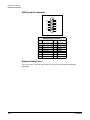
RIMM Memory Slots
The HP Workstation x2100 has four RIMM memory sockets for installing two or four
RDRAM memory modules:
•
•
•
•
Figure 2-7
RIMM A1
RIMM A2
RIMM B1
RIMM B2
RIMM Memory Slots
Each pair of memory sockets must contain identical memory modules (identical in size,
speed, and type). That is, sockets A1 and B1 must contain identical modules, and sockets
A2 and B2 must contain identical modules (or continuity modules).
If you install only two RDRAM modules, use the sockets marked A1 and B1. The other
two sockets (A2 and B2) must contain continuity modules.
Each RIMM socket is connected to the SMBus.
Read/Write Buffers
The MCH defines a data-buffering scheme to support the required level of concurrent
operations and provide adequate sustained bandwidth between the DRAM subsystem
and all other system interfaces (CPU, AGP, and PCI).
42
Chapter 2
System Board
Memory Controller Hub (82850)
System Clocking
The MCH has the following clock input pins:
•
Differential BCLK0/BCLK1 for the host interface
•
66 MHz clock input for the AGP and hub interface
•
Differential CTM/CTM# and CFM/CFM# for each of the two RAC’s.
Clock synthesizer chip(s) are responsible for generating the system host clocks, AGP and
hub interface clocks, PCI clocks and RDRAM clocks. The MCH provides two pairs of
feedback signals to the Direct Rambus Clock Generator (DRCG) chips to keep the host
and RDRAM clocks aligned. The host speed is 100 MHz. The RDRAM speed is 300 MHz
or 400 MHz. The MCH does not require any relationship between the BCLK host clock
and the 66 MHz clock generated for AGP and hub interfaces; they are totally
asynchronous from each other. The AGP and hub interfaces run at a constant 66 MHz
base frequency. The hub interface runs at 4x. AGP transfers may be 1x/2x/4x.
Chapter 2
43
System Board
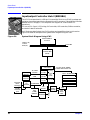
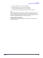
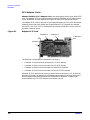
Input/output Controller Hub 2 (82801BA)
Input/output Controller Hub 2 (82801BA)
The ICH2 is encapsulated in a 360-pin Enhanced Ball Grid Array (EBGA) package and
resides on the system board just underneath the AGP connector. It provides the interface
between the PCI bridge (PCI 2.2 compliant with support for 32-bit 33MHz PCI
operations),
PCI-to-Low Pin Count (LPC) bridge, IDE controller, USB controller, SMBus controller,
and Audio Codec’97 controller.
You’ll find more detail about the ICH2 functions and capabilities later in this section.
Figure 2-8 shows an example of the system block diagram using the ICH2.
Figure 2-8
System Block Diagram Using ICH2
Intel Pentium IV
Processor
Address (36)
Control
Data (64)
System Bus
I850 Memory
Controller Hub
(MCH)
I/O Controller Hub
(ICH2) 82801BA
2 IDE
connectors
4 USB
connectors
Parallel
and serial
ports
44
IDE
Controller
USB
PCI Bridge
CS audio
codec
(CS4280)
Slot 1 - 32-bit/33MHz
4 x USB
Controller
DMA
Controller
SM Bus
Controller
Slot 3 - 32-bit/33MHz
Super
I/O
LPC/FWH link
NS 87364
FirmWare
Hub
(FWH)
82802AA
Slot 2- 32-bit/33MHz
Slot 4 - 32-bit/33MHz
Slot 5 - 32-bit/33MHz
MaxiLife
Monitoring Chip
Lan
Interface
Serial
EEPROM
SMBus
Keyboard,
mouse,
and floppy
ATA/100 2
channels
PCI bus (32-bit, 33MHz)
133MB/s data transfer rate
Fans
LCD
Status
Panel
Chapter 2
System Board
Input/output Controller Hub 2 (82801BA)
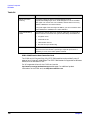
The following table shows the available ICH2 features, and the following sections
discuss them.
Feature
•
Multifunction PCI bus interface:
—
—
—
—
Feature
•
Enhanced DMA controller:
— Two 82C37 DMA controllers
— PCI DMA with two PC/PCI channels in
PCI at 32-bit 33MHz
PCI 2.2 specification
133MB/sec data transfer rate
Master PCI device support for as many
as five devices
pairs
— LPC DMA
— DMA collection buffer to provide Type-F
DMA performance for all DMA channels
•
USB, supporting:
•
— USB 1.1 compliant
— UHCI implementation with four USB
— Two cascaded 82C59 controllers
— Integrated I/O APIC capability
— 15 interrupt support in 8259 mode, 24
ports for serial transfers at 1.2 or
1.5Mbit/sec
— Wake-up from sleeping states
— Legacy keyboard/mouse software
•
Power Management Logic:
supported in I/O APIC mode
— Serial interrupt protocol
•
— ACPI 1.0 compliant
— Support for APM-based legacy power
—
—
—
—
—
•
Integrated IDE controller:
— Independent timing of as many as four
drives
Ultra ATA/100 mode (100MB/sec)
Ultra ATA/66 mode (66MB/sec)
Ultra ATA/33 mode (33MB/sec)
PIO mode four transfers as fast as
14MB/sec
— Separate IDE connections for primary
and secondary cables
— Integrated 16 x 32-bit buffer for IDE
PCI burst transfers
— Write ping-pong buffer for faster write
performances
—
—
—
—
management for non-ACPI
implementations
ACPI defined power states (S1, S3, S4,
S5)
ACPI power management timer
SMI generation
All registers readable/restorable for
proper resume from 0V suspend states
PCI PME#
Real-time clock, supporting:
Interrupt Controller:
•
— 256-byte battery-backed CMOS RAM
— Hardware implementation to indicate
System TCO reduction circuits:
— Timers to generate SMI# and reset upon
— Timers to detect improper processor
century rollover
reset
— Integrated processor frequency strap
logic
•
Timers based on 82C54:
•
— System timer, refresh request, speaker
SMBus
— Host interface allows processor to
tone output
communicate via SMBus
— Compatible with two-wire I2C bus
•
Chapter 2
System timer, refresh request, speaker tone
output
•
GPIO:
— TTL, Open-Drain, Inversion
45
System Board
Input/output Controller Hub 2 (82801BA)
Feature
Feature
•
FWH interface
•
3.3V operation with 5V tolerant buffers for
IDE and PCI signals
•
241 BGA package
•
Alert-On-LAN (AOL) support
ICH2 Features
ICH2 Architecture
The ICH2 interface architecture ensures that the I/O subsystems, both PCI and the
integrated I/O features (for example, IDE, AC’97, and USB), receive adequate
bandwidths.
By placing the I/O bridge directly on the ICH2 interface, and no longer on the PCI bus,
the ICH2 architecture ensures that the I/O functions obtain the bandwidth necessary for
peak performance.
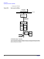
ICH2 PCI Bus Interface
The ICH2 PCI provides the interface to a PCI bus interface operating at 33MHz. This
interface implementation is compliant with PCI 2.2 specification, supporting as many as
five external PCI masters in addition to the ICH2 requests. The PCI bus can reach a
data transfer rate of 133MB/sec. The maximum PCI burst transfer can be between
256 bytes and 4KB. It also supports advanced snooping for PCI master bursting, and
provides a prefetch mechanism dedicated for IDE read.
For a list of ICH2 interrupts, see the table on page 60.
SMBus Controller
The System Management (SM) bus is a two-wire serial bus that runs at a maximum of
100kKHz. The SMBus host interface allows the processor to communicate with SMBus
slaves and an SMBus slave interface that allows external masters to activate
power-management events. The bus connects to sensor devices that monitor some of the
hardware functions of the system board, both during system boot and run-time.
For a description of the devices on the SMBus, see page 49. For information about the
MaxiLife ASIC, see page 51.
Low Pin Count Interface
The ICH2 implements the LPC interface 1.0 specification.
Enhanced USB Controller
The USB controller provides enhanced support for the Universal Host Controller
Interface (UHCI). This includes support that allows legacy software to use a USB-based
keyboard and mouse. The USB supports four stacked connectors on the back panel.
These ports are built into the ICH2, as standard USB ports.
The ICH2 is USB 1.1 compliant.
46
Chapter 2
System Board
Input/output Controller Hub 2 (82801BA)
USB works only if you’ve enabled the USB interface within the HP Setup program.
Currently, only Microsoft Windows 95 SR2.1, Windows 98, and Windows 2000 provide
USB support.
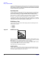
AC’97 Controller
The AC’97 controller is a single-chip CS4299 audio controller that provides full audio
features for the HP Workstation x2100.
For information about the CS4299 audio solution, see page 48.
IDE Controller
The IDE controller is implemented as part of the ICH2 chip and has PCI-Master
capability. Two independent ATA/100 IDE channels are provided with two connectors
per channel. You can connect two IDE devices (one master and one slave) per channel. To
guarantee data transfer integrity, you must use Ultra-ATA cables for Ultra-ATA modes
(Ultra-ATA/33, Ultra-ATA/66, and Ultra-ATA/100).
The PIO IDE transfers as fast as 14MB/sec, and the system supports Bus Master IDE
transfer rates of as fast as 66MB/sec. The IDE controller integrates 16 x 32-bit buffers
for optimal transfers.
You can mix a fast and a slow device (for example, a hard disk and a CD-ROM) on the
same channel without affecting the performance of the faster device. The BIOS
automatically determines the fastest configuration that each device supports.
DMA Controller
The seven-channel DMA controller incorporates the functionality of two 82C37 DMA
controllers. Channels zero to three are for 8-bit count-by-byte transfers, whereas
channels five to seven are for 16-bit count-by-word transfers. (For allocated DMA
channel allocations, see the table on page 74.) You can program any two of the seven
DMA channels to support fast Type-F transfers.
The ICH2 DMA controller supports the LPC DMA. The LPC interface supports Single,
Demand, Verify, and Incremental modes. Channels zero to three are 8-bit, whereas
channels five to seven are 16-bit. Channel four is reserved as a generic bus master
request.
Interrupt Controller
The interrupt controller is equivalent in function to the two 82C59 interrupt controllers.
The two interrupt controllers are cascaded so that 14 external and 2 internal interrupts
are possible. In addition, the ICH2 supports a serial interrupt scheme and also
implements the I/O APIC controller. The table on page 60 shows how the master and
slave controllers are connected.
Timer/Counter Block
The timer/counter block contains three counters that are equivalent in function to those
found in one 82C54 programmable interval counter/timer. These three counters provide
the system timer function and speaker tone. The 14.318MHz oscillator input provides
the clock source for these three counters.
Chapter 2
47
System Board
Input/output Controller Hub 2 (82801BA)
Advanced Programmable Interrupt Controller
You can use the APIC, which is incorporated in the ICH2, in either single-processor or
multiprocessor systems, whereas the standard interrupt controller supports only
single-processor systems.
Real Time Clock
The RTC is 146818A-compatible, with 256 bytes of CMOS. The RTC performs two key
functions:
•
Keeps track of the time
•
Stores system data
The RTC operates on a 32.768KHz crystal and a separate 3V lithium battery that
provides up to seven years of protection for an unplugged system. The RTC also supports
two lockable memory ranges. By setting bits in the configuration space, you can lock two
8-byte ranges to read and write accesses. This procedure prevents unauthorized reading
of passwords or other security information. Another feature is a date alarm that allows
for a schedule wake-up event as much as 30 days in advance.
Enhanced Power Management
The ICH2’s power-management functions include enhanced clock control, local and
global monitoring support for 14 individual devices, and various low-power (suspend)
states. A hardware-based thermal management circuit permits software-independent
entry points for low-power states.
The ICH2 includes full support for the Advanced Configuration and Power Interface
(ACPI) specifications.
Crystal CS4299 Integrated PCI Audio
Based on the earlier crystal audio controller, the CS4299 extends these features to
include, among many other enhancements, PC’98 and PC’99 compliancy for multimedia
desktops that require high-quality audio.
Features of the CS4299 include:
48
•
AC’97 2.1 compatibility
•
Industry-leading mixed-signal technology
•
20-bit stereo digital-to-analog converter and 18-bit analog-to-digital converter
•
High-quality pseudo-differential CD input
•
Mono microphone input
•
Analog line-level stereo inputs for LINE IN
•
Stereo line-level output
•
Compliance with Microsoft’s PC’98 and PC’99 audio performance requirements
Chapter 2
System Board
Input/output Controller Hub 2 (82801BA)
The CS4299 introduces a new architecture that is different from the one used with the
CS4280-CS4297 pair.
Figure 2-9
CS4280-CS4297 and CS4299 Architecture
Previous
Architecture
New
Architecture
North
Bridge
North
Bridge
PCI Slots
South
Bridge
PCI Bus
CS4280 digital
controller
South
Bridge
Audio controller link
Audio controller link
CS4299
CS4297
Devices On The SMBus
The SMBus is a subset of the I2C bus. It is a two-wired serial bus that runs at a
maximum speed of 100KHz. The SMBus monitors some of the system board’s hardware
functions (for example, voltage levels, temperature, fan speed, memory presence, and
type), both at system boot and during normal run-time. The SMBus controller, located in
the ICH2, controls the SMBus.
The following devices are connected to the SMBus:
Chapter 2
•
LCD status panel
•
One serial EEPROM MaxiLife (also includes backup values of CMOS settings)
•
PCI slot 5 ready for Alert-On LAN (AOL) from a hardware level
•
ICH2 SMBus master controller 100KHz maximum
•
MaxiLife for hardware management, bus master controller
•
One LM75 thermal sensor on the system board
•
One ADM1024 hardware-monitoring sensor
49
System Board
Input/output Controller Hub 2 (82801BA)
•
Figure 2-10
RIMM serial EEPROM
Devices on the SMBus
Intel Pentium IV
Processor
with L2 cache memory
System Bus
I850 Memory
Controller Hub
(MCH)
82840-QP
HUB LINK 8
(233MB/s data
transfer rate)
I/OController
Controller Hub
I/O
Hub
(ICH2) 82801BA
(ICH2)
82801AA
IDE
Controller
PCI bridge
CS audio
codec
(CS4299)
DMA
Controller
SMBus
Controller
SMBus
4 x USB
Controller
Serial
EEPROM
MaxiLife
Monitoring Chip
Fans
LCD
Status
Panel
ICH2 SMBus Master Controller
The ICH2 provides a processor-to-SMBus controller. All access performed to the SMBus
occurs through the ICH2 SMBus interface. Typically, the processor has access to all the
devices connected to the SMBus.
50
Chapter 2
System Board
Input/output Controller Hub 2 (82801BA)
RIMM Sockets
Each RIMM socket is connected to the SMBus. The 168-pin RIMM modules include a
256-byte I2C serial EEPROM. The first 128 bytes contain general information, including
the DRAM chips’ manufacturer’s name, RIMM speed rating, RIMM type, and so on. You
can use the second 128 bytes of the serial EEPROM to store data online.
AS98127F
The AS98127 chip is a hardware-monitoring sensor dedicated to the processor
temperature. This chip uses the thermal diodes integrated into each processor cartridge
and makes the temperature information available through the SMBus. It also monitors
processor power supply voltages.
Serial EEPROM
This is the nonvolatile memory that holds the default values for the CMOS memory (in
the event of battery failure).When you install a new system board, the serial EEPROM
will have a blank serial number field. The BIOS automatically detects this, and the
system prompts you for the serial number printed on the identification label on the back
of the workstation.
The computer uses 16KB of serial EEPROM implemented within two chips. Serial
EEPROM is ROM in which the application of appropriate electrical signals can return
one byte at a time to its unprogrammed state. In effect, you can make serial EEPROM
behave like very slow, nonvolatile RAM. It is used for storing the tattoo string, the serial
number, and the parameter settings for the Setup program as well as MaxiLife
firmware.
LM75 Temperature Sensor
The LM75 temperature sensor and alarm reside on the system board. The sensor
measures the temperature in various areas of the system board. The system uses this
information to regulate fans.
HP MaxiLife Hardware-monitoring Chip
MaxiLife is a hardware-monitoring chip on the system board. Its functions include:
•
•
•
•
•
•
•
Figure 2-11
Chapter 2
On/off and reset control
Status panel management (lock button, LEDs)
Hardware monitoring (temperature and voltage)
Early diagnostics (CPU, memory, PLLs, boot start)
Run-time diagnostics (CPU errors)
Fan speed regulation
Other miscellaneous functions (such as special OK/FAIL symbols based on a smiling
face)
HP MaxiLife Hardware-Monitoring Chip
51
System Board
Input/output Controller Hub 2 (82801BA)
The integrated microprocessor includes the following:
•
•
•
•
•
•
Synopsys cell based on Dallas “8052” equivalent
2KB boot ROM
256 bytes of data RAM
I2C cell
Analog-to-Digital (ADC) with five entries
Additional glue logic for interrupt control, fan regulation, and a status panel control
MaxiLife downloads its code in 96 milliseconds from an I2C serial EEPROM. The total
firmware (MaxiLife 8051-code, running in RAM) size is 14KB. As it exceeds the 2KB
program RAM space, a paging mechanism swaps code as necessary, based on a 512-byte
buffer. The first 2KB pages of firmware code is crucial because it controls the initial
power on/reset to boot the system. This initial page is checked with a null-checksum test
and the presence of MaxiLife markers (located just below the 2KB limit).
MaxiLife is not accessible in I/O space or memory space of the system platform, but only
through the SMBus (which is a subset of the I2C bus), via the ICH2. Its I2C cell may
operate either in slave or master mode, switched by firmware, or automatically in the
event of Arbitration loss.
As a monitoring chip, MaxiLife reports critical errors at start-up, and is therefore
powered by Vstandby (3.3V) power. For MaxiLife to work, the workstation must be
connected to a grounded outlet. This enables the workstation’s hardware-monitoring
chip to be active, even if the system has been powered off.
Test Sequence And Error Messages
For detailed information about the different test sequences and error messages, see
“MaxiLife Test Sequence And Error Messages” on page 78.
52
Chapter 2
System Board
Input/output Controller Hub 2 (82801BA)
MaxiLife Architecture
The MaxiLife chip continuously monitors temperature and voltage sensors located in
critical regions on the system board. This chip receives data about the various system
components via a dedicated I2C bus, which is a reliable communications bus to control
the integrated circuit boards.
Figure 2-12
MaxiLife Architecture
LCD Status Panel
Temperature
Sensor
Voltage Sensor
Serial
EEPROM
Speed up/slow
down
HP MaxiLife
I2C Bus
Memory
Hardwaremonitoring
ASIC
NOTE
Chapter 2
System Fans
Memory
AGPset
MaxiLife is powered by VSTBY. Therefore, MaxiLife is functional as soon as the power
cord is plugged in.
53
System Board
Input/output Controller Hub 2 (82801BA)
Devices On The LPC Bus
Figure 2-13 illustrates the devices connected to the LPC bus.
Figure 2-13
Devices on the LPC Bus
Intel Pentium IV
Processor
System Bus
I850 Memory
Controller
Hub (MCH)
82840-QP
HUB LINK 8
I/OController
Controller Hub
I/O
Hub
(ICH2) 82801BA
(ICH)
82801AA
IDE
Controller
PCI bridge
CS audio
Keyboard,
mouse,
and floppy
Parallel and
serial ports
Super
I/O
LPC / FWH Link
NS 87364
codec
4 x USB
Controller
(CS4299)
DMA
Controller
SMBus
Controller
FirmWare
Hardware
(FWH) 82802
The Super I/O Controller
The Super I/O chip (NS 87364) provides control for two FDD devices, two serial ports,
one bidirectional multimode parallel port, and a keyboard and mouse controller.
Device
Super I/O
Index
2Eh
Data
2Fh
Serial/Parallel Communications Ports
The 9-pin serial ports (whose pin layouts are depicted on page 114) support RS-232-C
and are buffered by 16550A UARTs, with 16-byte FIFOs. You can program them as
COM1, COM2, COM3, COM4, or you can disable them.
The 25-pin parallel port (also depicted on page 115) is Centronics compatible, supporting
IEEE 1284. You can program the port as LPT1, LPT2, or you can disable it. It can
operate in the following modes:
54
Chapter 2
System Board
Input/output Controller Hub 2 (82801BA)
•
Standard mode (PC/XT, PC/AT, and PS/2 compatible).
•
Bidirectional mode (PC/XT, PC/AT, and PS/2 compatible).
•
Enhanced mode (enhanced parallel port, EPP, compatible).
•
High-speed mode (MS/HP extended capabilities port, ECP, compatible).
FDC
The integrated floppy disk controller (FDC) supports any combination of two of the
following: tape drives, 3.5-inch flexible disk drives, 5.25-inch flexible disk drives. It is
software- and register-compatible with the 82077AA, and IBM-compatible. It has an A
and B drive-swapping capability and a non-burst DMA option.
Keyboard And Mouse Controller
The computer has an 8042-based keyboard and mouse controller. See page 113 for
connector pin layouts.
Chapter 2
55
System Board
FirmWare Hub (82802AB)
FirmWare Hub (82802AB)
The FWH (also known as flash memory) is connected to the LPC bus. It contains 4Mbit
(512KB) of flash memory.
The hardware features of the FWH include:
•
Random Number Generator (RNG)
•
Five General Purpose Inputs (GPI)
•
Register-based block locking
•
Hardware-based locking
An integrated combination of logic features and nonvolatile memory:
•
Enables better protection for the storage and update of system code and data.
•
Adds flexibility through additional GPIs.
•
Allows for quicker introduction of security/manageability features.
The following table outlines the available FWH features
Feature
•
Platform compatibility:
Feature
•
— Enables security-enhanced platform
— FWH interface for system operation
infrastructure
— Address/Address Multiplexed (A/A Mux)
— Part of the Intel I840 chipset
•
FWH interface mode:
Two configurable interfaces:
interface
•
— Five signal communication interface supporting
4Mbits of flash memory for system code/data
nonvolatile storage:
— Symmetrically blocked, 64KB memory
x8 reads and writes
sections
— Register-based read and write protection for each
— Automated byte program and block erase
code/data storage blocks
through an integrated Write State
Machine (WSM)
— Five additional GPIs for system design and
flexibility
— A hardware RNG
— Integrated Command User Interface (CUI) for
requesting access to locking, programming, and
erasing options. Also handles requests for data
residing in status, ID, and block lock registers.
— Operates with 33MHz PCI clock and 3.3V I/O
•
A/A Mux Interface/Mode, supporting:
— 11-pin multiplexed address and 8-pin data I/O
interface
— Fast on-board or out-of-system programming
56
•
Power supply specifications:
— Vcc: 3.3V +/- 0.3V
— Vpp: 3.3V and 12V for fast programming,
80ns
Chapter 2
System Board
FirmWare Hub (82802AB)
Feature
•
Industry standard packages:
Feature
•
Case temperature operating range
— 40L TSOP or 32L PLCC
The FWH includes two hardware interfaces:
•
FWH interface
•
A/A Mux interface
The Interface Configuration (IC) pin on the FWH provides the control between these
interfaces. You must select the interface mode prior to power-up or before return from
reset (RST# or INIT# low to high transition).
The FWH interface works with the ICH2 during system operation, while the A/A Mux
interface is designed as a programming interface for component preprogramming.
An internal CUI serves as the control center between the FWH and A/A Mux interfaces,
and internal operation of the nonvolatile memory. A valid command sequence written to
the CUI initiates device automation. An internal WSM automatically executes the
algorithms and timings necessary for block erase and program operations.
Chapter 2
57
System Board
System Bus
System Bus
The system bus of the Pentium IV processor is implemented in the Gunning Transceiver
Logic (GTL)+ technology. This technology features open-drain signal drivers that are
pulled up through resistors at bus extremities to the operating voltage of the processor
core. These resistors also act as bus terminators and are integrated in the processor and
in the 82850 MCH.
Figure 2-14
The System Bus
Socket 423
Intel Pentium IV
Processor
Address (32)
Control
100MHz two-way system bus (data bus runs at
4 x 100MHz, 3.2GB/s
transfer rate)
Data (64)
1.5V
AGP
Pro
Connector
AGP 4x Bus
(133MHz
(1GB/sec data
transfer rate)
850
Dual Rambus channel
Memory
Controller Hub
3.2GB/s at
(MCH)
400MHz data
82850
transfer rate)
4 onboard RIMM
sockets
supporting
RDRAM memory
HUB LINK 8
(266MB/s
data transfer
rate)
I/O Controller Hub
(ICH) 82801AA
The supported operating frequency of the GTL+ bus for the Pentium IV is 100MHz. The
width of the data bus is 64 bits, whereas the width of the address is 32 bits. Data bus
transfers occur at four times the system bus, at 400MHz. Along with the operating
frequencies, the processor voltage is set automatically.
The control signals of the system bus allow the implementation of a “split -transaction”
bus protocol. This allows the Pentium IV processor to send its request (for example, for
the contents of a given memory address) and release the bus, rather than waiting for the
result. Therefore, processor can accept another request. The MCH, as the target device,
then requests the bus again when it is ready to respond, and sends the requested data
packet. As many as four transactions can be outstanding at any given time.
Intel Pentium IV Processor
The Pentium IV processor has several features that enhance performance:
•
58
Data bus frequency of 400MHz
Chapter 2
System Board
System Bus
•
Dual independent bus architecture, which combines a dedicated 64-bit Level 2 cache
bus (supporting 256KB), plus a 64-bit system bus that enables multiple
simultaneous transactions
•
MMX2 technology, which gives higher performance for media
communications, and 3D applications
•
Dynamic execution to speed up software performance
•
Internet Streaming SIMD Extensions 2 (SSE2) for enhanced floating point and 3D
application performance
•
Uses multiple low-power states, such as AutoHALT, Stop-Grant, Sleep, and Deep
Sleep to conserve power during idle times
The Pentium IV processor is packaged in a pin grid array (PGA) that fits into a PGA423
socket (423-pin Zero Insertion Force—ZIF—socket).
Processor Clock
The 100MHz system bus clock is provided by a PLL. The processor core clock is derived
from the system bus by applying a ratio. This ratio is fixed in the processor. The
processor then applies this ratio to the system bus clock to generate its CPU core
frequency.
Bus Frequencies
The system board contains a 14.318MHz crystal oscillator. This frequency is multiplied
to 133MHz by a phase-locked loop. An internal clock multiplier within the processor
further scales this number.
The bus frequency and the processor voltage are set automatically.
Voltage Regulation Module (VRM)
One VRM is integrated on the system board, complying with VRM specification 9.0. The
system supports high-current and low-voltage processors.
The processor requires a dedicated power voltage to supply the CPU core and Level 2
cache. The processor codes through Voltage Identification (VID) pins with a required
voltage level of 1.30V to 2.05V. The VID set is decoded by the VRM on the system board
that in return supplies the required power voltage to the processor. Note, however, that
voltage may vary from one processor model to another.
Cache Memory
The Pentium IV integrates the following cache memories on the same die as the
processor cache:
•
A trace instruction and Level 1 data cache. The trace cache is 4-way set associative.
•
A 256KB Level 2 cache. The Level 2 cache is 8-way associative.
Intel sets the amount of cache memory at the time of manufacture. You can’t change the
value.
Chapter 2
59
System Board
Assigned Device Interrupts
Assigned Device Interrupts
I/o Controller Hub Interrupts
Device
Reference
Name
REQ/
GNT
IDSEL
AD[xx]
ID
Chip-set Interrupt Connection
INTA
INTB
INTC
INTD
AC’97 audio
controller
CS4280
4
(ICH2)
5
21
—
A
—
—
USB controller
—
—
—
—
A
—
—
—
AGP slot
J34
—
0
16
A
B
—
—
PCI 32-bit slot #1
J37
1
(ICH2)
6
22
C
D
A
B
PCI 32-bit slot #2
J38
0
(ICH2)
8
24
A
B
C
D
PCI 32-bit slot #5
(LAN card)
J42
5
(ICH2)
11
27
B
C
D
A
REQ/G
NT
ID
PCI 64-bit Hub Interrupts
Device
Reference
Name
IDSEL
AD[xx]
Interrupt Requests (IRQ)
0
1
2
3
4
5
6
7
8
Ultra-Wide SCSI U160
controller
AIC-7892
2 (P64H) 9
25
— — — — — — — — A
PCI 32-bit slot #3
J39
1 (P64H) 4
20
— — — — A B C D —
PCI 32-bit slot #4
J40
0 (P64H) 7
23
A B C D — — — — —
Interrupt Controllers
The system has an interrupt controller that is equivalent in function to that of two
82C59 interrupt controllers. The following table shows how the interrupts are connected
to the APIC controller. The IRQs are numbered sequentially, starting with the master
controller, and followed by the slave (both of 82C59 type).
60
Chapter 2
System Board
Assigned Device Interrupts
Although you can use the Setup program to change some of the settings, the following
address map isn’t completely BIOS dependent but is determined partly by the operating
system. Note that some of the interrupts are allocated dynamically.
APIC Controller
Interrupt Source
of device
Input
Interrupt Signalling on
(PIC
mode)a
(APIC
modes)
INTA - PCI slot 3 (32/33)
P64H
IRQ0
BT_INT
APIC bus
INTB - PCI slot 3 (32/33)
P64H
IRQ1
BT_INT
APIC bus
INTC - PCI slot 3 (32/33)
P64H
IRQ2
BT_INT
APIC bus
INTD - PCI slot 3 (32/33)
P64H
IRQ3
BT_INT
APIC bus
INTA - PCI slot 4 (32/33)
P64H
IRQ4
BT_INT
APIC bus
INTB - PCI slot 4 (32/33)
P64H
IRQ5
BT_INT
APIC bus
INTC - PCI slot 4 (32/33)
P64H
IRQ6
BT_INT
APIC bus
INTD - PCI slot 4 (32/33)
P64H
IRQ7
BT_INT
APIC bus
INTA - onboard SCSI controller
P64H
IRQ8
BT_INT
APIC bus
AGP - INTA, PCI Slot 1 - INTC, PCI
Slot 2 - INTA, PCI Slot 5 - INTB
ICH2
INTA
INT
APIC bus
PCI Audio - INTA, AGP - INTB, PCI
Slot 1 - INTD, PCI Slot 2 - INTB,
PCI Slot 5 - INTC
ICH2
INTB
INT
APIC bus
BT_INT, PCI Slot 1 - INTA, PCI
Slot 2 - INTC, PCI Slot 5 - INTD
ICH2
INTC
INT
APIC bus
USB - INTA, PCI Slot 1 - INTB, PCI
Slot 2 - INTD, PCI Slot 5 - INTA
ICH2
INTD
INT
APIC bus
Device on Primary IDE Channel
ICH2
IRQ14
INT
APIC bus
Device on Secondary IDE Channel
ICH2
IRQ15
INT
APIC bus
Serial Interrupt from Super I/O
ICH2
SERIRQ
INT
APIC bus
a. In PIC mode, the interrupts signaled to the P64H are chained as INTC to the ICH2.
Three major interrupt modes are available:
NOTE
Chapter 2
•
PIC mode: This mode uses only legacy interrupt controllers, so only one processor
can be supported. Because this system has dual-processor capability, Windows NT
doesn’t choose this mode as the default. However, during Windows NT installation,
you can select this mode.
•
Virtual wire mode: This mode is implemented with APIC controllers in the ICH2
and P64H and used during boot time. The virtual wire mode allows the transition to
the symmetric I/O mode. In the virtual wire mode, only one processor executes
instructions.
•
Symmetric I/O mode: This mode is implemented with APIC controllers in the
ICH2 and P64H and allows for multiple processor operations.
In PIC mode and virtual wire mode, PCI interrupts are routed to the INT line. In
symmetric I/O mode, PCI interrupts are routed to the I/O APIC controllers and
forwarded over an APIC bus to the processors.
61
System Board
Assigned Device Interrupts
PCI IRQ Lines
PCI devices generate IRQs using up to four PCI IRQ lines (INTA#, INTB#, INTC#, and
INTD#).
PCI interrupts can be shared; several devices can use the same interrupt. However,
optimal system performance is reached when minimizing the sharing of interrupts.
Refer to page 60 for a table of the PCI device interrupts.
62
Chapter 2
3
Chapter 3
System BIOS
63
System BIOS
Overview
Overview
This chapter summarizes the HP Workstation x2100’s Setup program and BIOS.
Chapter 4, “Tests And Error Messages,” describes the POST routines.
The BIOS is based on the core Phoenix BIOS, which includes 4Mbits of flash memory,
support for PCI Specification 2.2, suspend to RAM, and RIMM or DIMM memory
modules.
The BIOS includes a boot ROM for the 3COM 3C905C and HP LAN cards.
The system ROM contains the Power-On Self-Test (POST) routines and the BIOS: the
system BIOS, video BIOS, and low-option ROM. This chapter (and Chapter 4) gives an
overview of the following:
•
Menu-driven Setup with context-sensitive help.
•
The address space, with details of the interrupts used.
•
POST routines, which are a sequence of tests the computer performs to ensure that
the system is functioning correctly. See Chapter 4 for information.
The system BIOS is identified by the version number IY.WM, where:
•
IY is a two-letter code indicating that it is for the x2100.
•
W is a one-digit code indicating the HP entity.
•
JG.W1.01US is the major BIOS version.
An example of a released version would look similar to the following: JG.W1.01US.
See page 70 for the procedure for updating the system ROM firmware.
64
Chapter 3
System BIOS
Overview
Using The HP Setup program
To run the Setup program, press F2 while the initial HP logo displays, immediately after
restarting the workstation.
Alternatively, press Esc to view the summary configuration screen. By default, this
screen displays for 15 seconds, but pressing any key stops this delay.
The band at the top of the Setup screen offers the following menus: Main, Advanced,
Security, Boot, Power, and Exit. Use the left and right arrow keys to select these menus.
The following screens are examples of a BIOS configuration.
Main Screen
The Main Screen shows a list of fields. To change a value press F7 or F8.
Main
PhoenixBIOS Setup Utility
Security
Boot
Advanced
BIOS Version:
IC.11.02
PnP OS
Reset Configuration Data:
[No]
[No]
System Time:
System Date:
[14:42:33]
[02/08/2000]
Power
Exit
Item-Specific Help
.
Key Click:
[Disabled]
Keyboard auto-repeat rate speed: [21.8 per Second]
Delay before auto-repeat:
[0.50
Second]
Numlock at Power-on:
[On]
F1
Help
ESC Exit
↑
↓
Select Item
F7/F8 Change Values
F9
←
→
Select Menu
Enter Select > Submenu
F10
Setup
Defaults
Previous
Values
Advanced Screen
The Advanced Screen doesn’t have the same structure as the Main Screen and Power
Screen. Instead of presenting a list of fields, it offers a list of submenus.
Advanced users use the Advanced Screen to carry out special system configurations.
Main
>>
>>
>>
>>
>>
>>
>>
>>
>>
>>
>>
>>
>>
Chapter 3
Advanced
Processors, Memory, and Cache
Floppy Disk Drives
IDE Devices
Integrated USB Interface
Integrated I/O Ports
Integrated Audio Device
AGP Configuration (Video)
PCI Device, slot #1
PCI Device, slot #2
PCI Device, slot #3
PCI Device, slot #4
PCI Device, slot #5
Integrated LAN
Security
Boot
Power
Exit
Item-Specific Help
.
65
System BIOS
Overview
Processors, Memory And Cache
Advanced
Processors, Memory, and Cache
Processor Type
CPU Speed
Pentium (R) 4
1500MHz
Microcode update version
[F24/4]
Memory Caching
Memory Error Checkinga
[Enabled]
[ECC]
Item-Specific Help
a. Only if the system detects ECC modules.
Floppy Disk Drives
Advanced
Floppy Disk Drives
Floppy Disk Controller
Floppy Disk Drive A
Floppy Disk Drive B
Item-Specific Help
[Enabled]
[1.44, 3 ”]
[Not installed]
IDE Devices
Advanced
IDE Devices
>>
>>
IDE Primary Master Device
IDE Primary Slave Device
[None]
[None]
>>
>>
IDE Secondary Master Device
IDE Secondary Slave Device
[None]
[None]
>>
>>
Large Disk Access Method
Integrated IDE Controller
[NT/DOS]
[Both Enabled]
Item-Specific Help
IDE Primary Master Device
Advanced
IDE Primary Master Device (HD 2564)
Item-Specific Help
Type
Multisector transfer
LBA Mode Control
32 bit I/O
Transfer Mode
ULTRA DMA Mode
66
Chapter 3
System BIOS
Overview
Integrated USB Interface
Advanced
Integrated USB Interface
USB Controller
Legacy Keyboard Emulation
Item-Specific Help
[Auto]
[Disabled]
Integrated I/O Ports
Advanced
Integrated I/O Ports
Parallel Port
Parallel Port Mode
Serial Port A
Serial Port B
Item-Specific Help
[Auto]
[ECP]
[Auto]
[Auto]
Integrated Audio Device
Advanced
Integrated Audio Device
Integrated Audio
Item-Specific Help
[Enabled]
AGP Configuration (Video)
Advanced
AGP Configuration (Video)
Graphic Aperture
Item-Specific Help
[64MB]
PCI Device, Slot #1
Advanced
PCI Device, Slot 1a
Option ROM Scan
Bus Master
Bus Latency Timer
Item-Specific Help
[Auto]
[Disabled]
[0040h]
a. PCI Slot #x have the same options as above. PCI Device, Slot 1 is only
an example.
Chapter 3
67
System BIOS
Overview
Integrated LAN
Advanced
Integrated LAN
Integrated Network:
Option ROM Scan
Bus Master
Bus Latency Timer
Item-Specific Help
[Enabled]
[Enabled]
[Disabled]
[0020h]
Security Screen
Submenus let you change the characteristics and values of the:
•
•
•
•
•
systems administrator password
user password
power-on password
boot device security
hardware protection
Main
Advanced
Security
Boot
Administrator Password
Clear
Set Administrator Password [Enter]
Clear Both Passwords
[Enter]
>>
User Password
Set User Password
Clear
[Enter]
Power-on Password
[Disabled]
Start from Floppy
Start from CD-ROM
Start from HDD
[Enabled]
[Enabled]
[Enabled]
Power
Exit
Item-Specific Help
.
Hardware Protection
Hardware Protection
Security
Hardware Protection
68
Write on Floppy
Disks
[Unlocked]
Secured Setup
Configuration
Hard Disk Boot Sector
[No]
Item-Specific
Help
[Unlocked]
Chapter 3
System BIOS
Overview
Boot Screen
This screen lets you select the order of the devices in which you want the BIOS to
attempt to boot the operating system:
•
Hard disk drives
•
Removable devices
The operating system assigns drive letters to these devices in the order that you specify.
During POST, if the BIOS unsuccessfully boots from one device, it attempts to boot from
the next device on the Boot Device Priority list until it finds an operating system.
Main
Advanced
Security
Boot
Power
Exit
Item-Specific Help
Quickboot Mode
[Enabled]
Display Option ROM Messages [Enabled]
>
Boot Device Priority
Power Screen
This screen lets you set the Standby Delay and Suspend Delay modes. Standby mode
slows down the processor, whereas Suspend mode saves energy. These options are
available only with Windows 95 RTM. For other operating systems (for example,
Windows 95 SR 2.5, Windows 98, and Windows 2000), use the control panel for similar
options.
Modem Ring enables or disables the system’s ability to return to full speed after an
Interrupt Request (IRQ) is generated. Network Interface enables or disables the
system’s ability to return to full speed after the network interface receives a specific
command.
Main
Chapter 3
Advanced
Security
Standby Delay
Suspend Delay
[Disabled]
[Disabled]
Suspend Wakeup
Modem Ring
Network Interface
[Enabled]
[Enabled]
Boot
Power
Exit
Item-Specific Help
69
System BIOS
Updating The System BIOS
Updating The System BIOS
You can download the latest system BIOS (standard flash operation) from HP’s Web site
at www.hp.com/go/workstationsupport. After accessing the site, select HP x2100
Workstation.
Instructions for updating the BIOS accompany the downloaded BIOS files and a BIOS
flash utility (flash.txt).
The BIOS update not only flashes the BIOS but also updates MaxiLife. Figure 3-1 shows
how the system BIOS flash operates.
Figure 3-1
System BIOS Flash Process
Boot
from
floppy
disk
Flash
BIOS
Reboot
Workstation
(press a key)
Flash
MaxiLife
Workstation
powers off
automaticall
CAUTION
Workstation
powers on
automaticall
Workstation
Boots
Don’t turn off the computer until the system BIOS update procedure has completed,
successfully or not; otherwise, irrecoverable damage to the ROM might occur.
Restoring BIOS Default Settings
BIOS and configuration issues may cause suspected hardware errors. If the BIOS
settings are wrong, perform the following steps to restore the BIOS to its default setting:
1. To access the Setup program, press F2 while the initial HP logo displays immediately
after restarting the workstation.
2. Press F9 to load the default settings from the Setup program.
3. In the main menu, set the Reset Configuration Data to Yes.
Take note of the system setup before you make any modifications to the BIOS.
If You Forget The Administrator Password
1. Turn off the workstation, disconnect the power cord and all cables, then remove the
cover.
2. Set switch 9 on the system board switch block to ON.
3. Replace the power cord, and restart the workstation.
4. When the Passwords have been cleared message appears, turn off the
workstation.
70
Chapter 3
System BIOS
Updating The System BIOS
5. Remove the power cord, and reset switch 9 back to OFF.
6. Replace the workstation’s cover, turn on the workstation, and let it complete its
startup routine.
7. After POST completes, press F2 when prompted to use the Setup program.
8. Set the administrator and new user passwords.
9. To save the new password and exit Setup, press Esc or select Exit Menu.
Clearing The CMOS
1. Turn off the workstation, disconnect the power cord and all cables, then remove the
cover.
2. Set the system board switch 8 to ON.
3. Replace the cover, and reconnect the power cord and video cable.
4. Reboot the workstation. A message similar to the following
will appear:
“Configuration has been cleared, set switch Clear to the ON position
before rebooting.”
5. Turn off the workstation, disconnect the power cord and video cable, and remove the
cover.
6. Set the system board switch 8 to OFF.
7. Replace the cover, and reconnect the power cord and data cables.
8. Turn on the workstation. Press F2 to run Setup, then press F9. The system
automatically downloads and saves the CMOS default values.
9. To save the configuration and exit Setup, press Esc .
Recovering The BIOS (Crisis Mode)
If the BIOS is corrupted and you can’t use the standard flash, use the BIOS Recovery
Mode (exceptional BIOS recovery operation) to restore the BIOS.
1. Obtain a bootable DOS floppy disk.
2. Copy the BIOS files onto the floppy disk. For information about how to download the
system BIOS, see page 70.
3. Create (or edit) the autoexec.bat file, which should contain the following line of text:
“phlash /c /mode=3 /s IY.W1.XX.FUL”
(Rename the BIOS filename with the filename on the floppy disk.)
4. Turn off the workstation, disconnect the power cord, and remove the cover.
5. Set switch 7 to ON.
6. Insert the floppy disk into the floppy disk drive.
7. Reconnect the power cord, and turn on the workstation.
8. The workstation boots from the floppy disk, then flashes the BIOS. During the flash
process, the screen remains blank. When you hear one long beep, the recovery
process is finished.
Chapter 3
71
System BIOS
Updating The System BIOS
9. Turn off the workstation. Remove the floppy disk from the drive.
Remove the power cord.
10. Set switch 7 back to OFF.
11. Replace the cover, reconnect the power cord, then reboot the
workstation.
72
Chapter 3
System BIOS
BIOS Addresses
BIOS Addresses
This section provides a summary of the main features of the HP system BIOS. This is
software that provides an interface between the computer hardware and the operating
system. For the procedure to update the system ROM firmware, see page 70.
System Memory Map
Reserved memory that accessory boards use must reside in the area from C8000h to
EFFFFh.
0000 0000 - 0000 03FF
Real-mode IDT
0000 0400 - 0000 04FF
BIOS data area
0000 0500 - 0009 FC00
Used by operating system
0009 FC00 - 0009 FFFF
Extended BIOS data area
000A_0000 - 000B_FFFF
Video RAM or SMRAM (not visible unless
in SMM)
000C 0000 - 000C 7FFF
Video ROM (VGA ROM)
000C 8000 - 000F FFFF
Adapter ROM, RAM, memory-mapped
registers, BIOS
000E 0000-000F FFFF
128KB BIOS (Flash/Shadow)
0001 0000-000F FFFF
Memory (1MB to 16MB)
0010 0000-001F FFFF
Memory (16MB to 32MB)
0020 0000-003F FFFF
Memory (32MB to 64MB)
0040 0000-007F FFFF
Memory (64MB to 128MB)
0080 0000-7FFF FFFF
Memory (128MB to 2GB)
FECO 0000
I/O APIC
FEEO 0000
Local APIC (each CPU)
FFF8 0000-FFFF FFFF
512KB BIOS (Flash)
HP I/O Port Map (I/O Addresses Used By The System, if
configured)
You access peripheral devices, accessory devices, and system controllers through the
system I/O space, which isn’t located in system memory space. The 64KB of addressable
I/O space comprises 8-bit and 16-bit registers (called I/O ports) located in the various
Chapter 3
73
System BIOS
BIOS Addresses
system components. When you install an accessory board, ensure that the selected I/O
address space is in the free area of the space reserved for accessory boards (100h to
3FFh).
Default Values for
I/O Address Ports
0000 - 0CF7
0020 - 0021
002E - 002F
0040 - 0043
0060, 0064
0061
0070
0070 - 0071
0080
0081 - 0083, 008F
0092
00A0 - 00A1
00C0 - 00DF
00F0 - 00FF
0170 - 0177
01F0 - 01F7
0278 - 027F
02E8 - 02EF
02F8 - 02FF
0372 - 0377
0378 - 037F
03B0 - 03DF
03E8 - 03EF
03F0 - 03F5
03F6
03F7
03F8 - 03FF
04D0 - 04D1
0778 - 077F
0CF8 - 0CFF
C000 C100 - C10F
Function
DMA controller 1
Master interrupt controller (8259)
Super I/O
Timer 1
Keyboard controller (reset, slow A20)
Port B (speaker, NMI status, and control)
Bit 7: NMI mask register
RTC and CMOS
Manufacturing port (POST card)
DMA low page register
PS/2 reset and Fast A20
Slave interrupt controller
DMA controller 2
Coprocessor error
Free (IDE secondary channel)
IDE primary channel
LPT 2
Serial port 4 (COM4)
Serial port 2 (COM2)
Free (IDE secondary channel, secondary floppy disk
drive)
LPT1
VGA
COM3
Floppy disk drive controller
IDE primary channel
Floppy disk drive controller
COM1
Interrupt edge/level control
LPT1 ECP
PCI configuration space
Power management I/O space and ACPI registers
SMBus I/O space
DMA Channel Controllers
The system permits only I/O-to-memory and memory-to-I/O transfers. The hardware
configuration doesn’t allow I/O-to-I/O or memory-to-memory transfers.
The system controller supports seven DMA channels, each with a page register that
extends the channel’s addressing range to 16MB.
74
Chapter 3
System BIOS
BIOS Addresses
The following table shows how the system allocates DMA channels.
DMA controller
Channel
Function
DMA 0
Free
DMA 1
Free if not used for parallel port in Setup
DMA 2
Floppy disk drive controller
DMA 3
Free if not used for parallel port in Setup
DMA 4
Used to cascade DMA channels 0-3
DMA 5
Free
DMA 6
Free
DMA 7
Free
Interrupt Controllers
The system’s interrupt controller is equivalent in function to two 82C59 interrupt
controllers. The following table shows how the interrupts are connected to the APIC
controller. The IRQs are numbered sequentially, starting with the master controller and
followed by the slave (both of 82C59 type).
Chapter 3
I/O APIC Input
IRQ
IRQ Description
INTIN0
ICH
INTIN1
IRQ1
Super I/O keyboard controller
INTIN2
IRQ0
ICH system timer
INTIN3
IRQ3
Super I/O - Used by serial port if enabled
INTIN4
IRQ4
Super I/O - Used by serial port if enabled
INTIN5
IRQ5
Free if not used for parallel port or audio
INTIN6
IRQ6
Super I/O - floppy disk controller
INTIN7
IRQ7
Super I/O - LPT1
INTIN8
IRQ8
ICH - RTC
INTIN9
IRQ9
Available for PCI devices
INTIN10
IRQ10
Available for PCI devices
INTIN11
IRQ11
Available for PCI devices
INTIN12
IRQ12
Super I/O - mouse
INTIN13
IRQ13
Coprocessor
INTIN14
IRQ14
ICH - Integrated IDE Controller (primary)
INTIN15
IRQ15
ICH - Integrated IDE Controller (secondary)
INTIN16
PCINTA
INTIN17
PCINTB
75
System BIOS
BIOS Addresses
I/O APIC Input
IRQ
INTIN18
PCINTC
INTIN19
PCINTD
INTIN20
TFPC IRQ
INTIN21
SCI IRQ
INTIN22
not
connected
INTIN23
ICH SMI
(not used)
IRQ Description
Three major interrupt modes are available:
NOTE
•
PIC mode: This mode uses only legacy interrupt controllers, so the system can
support only one processor. You can select this mode when you install Windows NT.
•
Virtual wire mode: This mode, which is implemented using the 82C59 interrupt
and the I/O APIC controller, is used during boot time. The virtual wire mode allows
the transition to the symmetric I/O mode. In the virtual wire mode, only one
processor executes operations.
•
Symmetric I/O mode: This mode is implemented using the I/O APIC controller and
allows for multiple processor operations.
In PIC mode and virtual wire mode, PCI interrupts are routed to the INT line. In
symmetric I/O mode, PCI interrupts are routed to the I/O APIC controllers and
forwarded over an APIC bus to the processors.
PCI IRQ Lines
PCI devices generate IRQs using up to four PCI IRQ lines (INTA#, INTB#, INTC#, and
INTD#).
PCI interrupts can be shared; several devices can use the same interrupt. However,
optimal system performance is reached when minimizing the sharing of interrupts.
Refer to page 60 for a table of the PCI device interrupts.
76
Chapter 3
4
Tests And Error Messages
This chapter describes:
•
•
•
•
Chapter 4
MaxiLife firmware test sequences and error messages
Preboot diagnostics error codes
Power-On Self-Test (POST) routines, which the computer’s ROM BIOS contains
Error messages and suggestions for corrective action
77
Tests And Error Messages
MaxiLife Test Sequence And Error Messages
MaxiLife Test Sequence And Error Messages
When you turn on the workstation, the system initiates the normal startup sequence,
which consists of the following steps:
•
•
•
•
Basic preboot diagnostics
BIOS launch
POST phase
Operating system boot phase
If the system detects any errors during the startup sequence, MaxiLife won’t necessarily
freeze the system. However, some critical hardware errors are fatal to the system and
prevent the system from starting. (For example, CPU socket and power supply
malfunctions can prevent the system from working.)
The system detects non-crucial errors both during preboot diagnostics and POST, in
which the BIOS boot process returns an error code. The system detects some errors only
during POST sequence; these errors produce the same process.
Finally, while the workstation is working, the system can report fan and temperature
controls. (For example, the system can report a fan error if a fan cable is disconnected.)
This type of error disappears as soon as you fix the problem (for example, reconnect the
fan cable).
The next sections describe the different diagnostics.
Basic Pre-boot Diagnostics
The first diagnostic, called basic preboot diagnostics, runs to check the presence of the
processors or terminators, power supply, hardware monitoring, and thermal sensors. If
you have a power cord connected to the workstation, the basic preboot diagnostics are
activated.
The preboot diagnostic tests run in order of priority, according to their importance to
computer functions.
78
Chapter 4
Tests And Error Messages
MaxiLife Test Sequence And Error Messages
On the HP Workstation x2100, the first detected error displays a message on the LCD
status panel. If an error occurs, one of the following screens displays.
Figure 4-1
Possible Error Messages
Control of some voltages:
12V, 3.3V, 1.8V, 2.5V, -5V
Presence of processor
ERROR
ERROR
Power Supply
CPU Socket
Missing or incorrectly installed
processor
If a power supply error occurs, a
cause could reside in the power
supply cabling or circuits
Figure 4-2 shows how the preboot diagnostics work when an error occurs.
Figure 4-2
Preboot Diagnostics Error
CPU or Terminator
Vcc State (5V)
Voltage 12V, 3.3V, 1.8V, 2.5V
Voltage CPU1
MaxiLife
Firmware
I2C Bus
Hardware
Monitoring
LCD Status
Panel
Temperature
Sensors
System
Memory
An error has been detected when
checking the processor. The
displayed error message could
indicate a missing or incorrectly
connected processor.
ERROR
CPU Socket
The following table shows the test sequence carried out, the type of error message, and
the action to take.
Table 4-1
Test
Error Code
Beep Codes
Action to Take
Presence a processor
CPU socket
1
Check that the processor and
correctly installed
Control of some voltages: 12V,
3.3V, 1.8V, 2.5V
Power supply
2
Check the power supply cable
and connectors, and processor
Check the hardware monitoring
No HW monitoring
System board problem
Check thermal sensor
Therm. sensor 90
System board problem
Check thermal sensor
Therm. sensor 92
System board problem
Chapter 4
79
Tests And Error Messages
MaxiLife Test Sequence And Error Messages
Pre-boot Diagnostics Error Codes
When a failure occurs prior to the operating system loading, the workstation beeps three
times, then begins a series of beeps. These beeps identify the part that needs
troubleshooting or replacement.
Number of beeps
80
Problem
1
Absent or incorrectly connected processor
2
Power supply is in protected mode
3
Memory modules not present, incompatible, or not functioning
4
Video controller failure
5
PnP/PCI initialization failure
6
Corrupted BIOS; you need to activate crisis-recovery procedure
7
System board failure
Chapter 4
Tests And Error Messages
POST Sequence And POST Error
POST Sequence And POST Error
In this phase, MaxiLife waits for any error messages that the BIOS may issue. If such an
error occurs, an error code appears on the monitor screen.
On the HP Workstation x2100, a screen similar to Figure 4-3 displays. The error code
that appears on the LCD status panel is the same as the one that appears on the monitor
screen. If the POST issues several error codes, only the last one is visible on the LCD
status panel.
Figure 4-3
POST Sequence and POST Error
ERROR
Keyboard Test
Figure 4-4 and Figure 4-5 show the different BIOS-generated errors.
Figure 4-4
BIOS-generated Errors
“BIOS” ERROR
BIOS
MaxiLife
“Spy System
Memory”
“read system
memory”
A time-out of three seconds
occurs before the message
appears on the LCD status
panel and video display
ERROR
System
Memory
BIOS Check sum
LCD Status Panel
Figure 4-5
BIOS-generated Errors
“BIOS”-Generated Errors
“No Video”
BIOS
MaxiLife
ERROR
No Video
Video
Slots
Beep Codes
LCD Status Panel
Table 4-2
Chapter 4
Test
Error Code
Incompatible memory modules
Mem miscompare
Beep Codes
3
Action to Take
Check that the memory
modules are of the same speed
and type
81
Tests And Error Messages
POST Sequence And POST Error
Table 4-2
(Continued)
Test
Error Code
Beep Codes
Action to Take
Presence of continuity modules
in the RIMM sockets
RIMM continuity
3
Check that the RDRAM
continuity modules are
installed
Compatibility speed rating of
installed RDRAM modules
RIMM speed
3
Check that the installed
RDRAM modules have the
same speed ratings
Compatibility of installed
RDRAM modules
RIMM devices
3
The 32-device limit per
RDRAM has been exceeded
Presence of memory modules
No RIMM
3
Check that the memory
modules are correctly installed
Availability of video controller
is checked by the BIOS. If an
error is detected, and it isn’t a
fatal error, the BIOS continues
its execution normally.
No video
4
Check that the video controller
is correctly installed
Note: No error is detected if a
monitor isn’t connected to an
installed video controller. This
isn’t a fatal error, and the
BIOS continues its normal
execution.
Operating System Boot Phase
If no error message appears at this stage of the system startup, the operating system
launches. The LCD status panel displays the system platform and a smiling icon.
Run-time Errors
During the normal usage of the workstation (and at boot), MaxiLife continually monitors
vital system parameters. These include: temperature errors, fan malfunctions, power
voltage drops and CPU problems.
82
Chapter 4
Tests And Error Messages
POST Sequence And POST Error
Table 4-3
Test
During normal usage,
HP MaxiLife continually
checks vital system
parameters. If an error
occurs, a message
appears on the LCD
panel.
Error Code
Action to Take
System FAN
System or chassis fan, fan cable
PCI FAN
PCI fan, fan cable
CPU 1 FAN
CPU fan, fan cable
CPU Throttle
Processor frequency has been lowered to
prevent over temp errors
CPU Shutdown
Processor has undergone an internal error
(IERR) or the processor temperature has risen
too quickly for CPU Throttle to be effective.
PCI temperature
Ambient or PCI temperature > 64˚C
Disk temperature
Disk temperature > 58˚C, or sensor unplugged
PSU 12 V error
Power supply unit failed. Try the following:
Power CPU error
•
Replace the power supply unit with a
known working one
•
If the problem persists, replace the system
board
PSU 3V3 error
PSU 2V5 error
PSU 1V8 error
PSU -5V error
Chapter 4
83
Tests And Error Messages
Main Menu
Main Menu
The main menu appears when you press any of the LCD buttons. (You can access the
MaxiLife LCD status panel even when the workstation is powered off.) The main menu
consists of three submenus:
•
•
•
System Info
Boot Steps
Boot Report
system info
Obtains information from the BIOS and the system’s serial EEPROM. This information
includes:
•
•
•
•
•
Product name
BIOS version
Serial number
Speed of processor
Size of memory for each socket
Figure 4-6 shows how the System Info obtains its information.
Figure 4-6
System Information
System Info
strings in
EEPROM
MaxiLife
HP x2100
Write
Info
Services
BIOS
DMI
Table
84
LCD Status Panel
Chapter 4
Tests And Error Messages
Main Menu
Boot Steps
Shows the POST codes during system startup. The BIOS provides the POST code, which
appears on the LCD panel as soon as it is available. If the system stops during startup,
the last successful boot-step POST code appears on the LCD. When you select Boot
Steps, the POST step appears on the LCD status panel during the subsequent boot
processes.
To ensure that MaxiLife is ready to display the first POST codes as soon as possible, the
preboot diagnostics aren’t executed when the system is booted with the Boot Steps
option selected. Figure 4-7 shows how Boot Steps obtains its information from the BIOS,
then displays a POST error if necessary.
Figure 4-7
Boot Steps
System Info
Boot Steps
Next
MaxiLife
HP x2100
Post Code 24
Ok
This is a toggle
item, which is
indicated with a
check mark
“Write
POST
Code”
“Write
POST
BIOS ERROR”
Error
Post Code XX
Boot Report
Runs a set of diagnostics that assess the system’s components. Results of the tests
appear on the LCD status panel, one after another, when you press the LCD
buttons.
Components are tested in sequence when the you press the Next button. When all
components have been checked, a diagnostic screen appears. Depending on the result of
the diagnostics, the screen could indicate either Diagnostics Done OK or FAIL.
At the end of the test, you can exit the diagnostic mode by pressing the
LCD button.
For more information about MaxiLife, refer to Chapter 7 “troubleshooting your hp
workstation x2100.”
Chapter 4
85
Tests And Error Messages
Order In Which POSTs Occur
Order In Which POSTs Occur
The POST executes each time the system is powered on or a reset is performed. The
POST process verifies the basic functionality of the system components and initializes
certain system parameters.
The POST starts by displaying a graphic screen of the HP PC Workstation’s logo when
you restart the system. If you want to view the POST details, press Esc to access the HP
Summary Screen.
If the POST detects an error, the screen switches to text mode and a detailed error
message appears on a View System Errors screen. On this screen, the error message
utility (EMU) not only displays the error diagnosis but suggests corrective action. (Refer
to page 93 for a brief summary.)
On the HP Workstation x2100, the LCD status panel displays either a message, a POST
code number (refer to Table 4-4), or an EMU code.
Devices such as memory and newly installed hard disks are configured automatically.
You don’t need to confirm the change.
During the POST, the system copies BIOS and other ROM data into high-speed shadow
RAM. The shadow RAM is addressed at the same physical location as the original ROM
in a manner that is completely transparent to applications. Therefore, shadow RAM
appears to behave as very fast ROM. This technique provides faster access to the system
BIOS firmware.
Table 4-4 lists the POST checkpoint codes and their associated beeps. See page 81 for
more details about preboot diagnostics error codes.
Table 4-4
POST Checkpoint Codes
Checkpoint
Code
86
POST Routine Description
MaxiLife LCD
Display Message
02h
Verify real mode
03h
Disable Non-Maskable Interrupt (NMI)
04h
Get CPU type
06h
Initialize system hardware
08h
Initialize chipset with initial POST values
09h
Set IN POST flag
POST Start
0Ah
Initialize CPU registers
CPU Regist. Init
0Bh
Enable CPU cache
0Ch
Initialize caches to initial POST values
0Eh
Initialize I/O component
I/O Init.
0Fh
Initialize the local bus IDE
IDE Init.
10h
Initialize power management
Beep
Codes
Chapter 4
Tests And Error Messages
Order In Which POSTs Occur
Table 4-4
POST Checkpoint Codes (Continued)
Checkpoint
Code
Chapter 4
POST Routine Description
MaxiLife LCD
Display Message
11h
Load alternate registers with initial POST
values
12h
Restore CPU control word during warm boot
13h
Initialize PCI bus mastering devices
14h
Initialize keyboard controller
16h
BIOS ROM checksum
17h
Initialize cache before memory autosize
18h
8254 timer initialization
1Ah
8237 DMA controller initialization
1Ch
Reset programmable interrupt controller
20h
Test DRAM refresh
RAM Refresh Test
22h
Test 8742 keyboard controller
Keyb. Ctrl. Test
24h
Set ES segment register to 4GB
26h
Enable A20 line
28h
Autosize DRAM
29h
Initialize POST memory manager
2Ah
Clear 512KB base RAM
2Ch
RAM failure on address linea
RAM Add. Failure
2Eh
RAM failure on data bits xxxx1 of low byte of
memory bus
RAM Data Low
2Fh
Enable cache before system BIOS shadow
30h
RAM failure on data bits xxxx1 of high byte
of memory bus
32h
Test CPU bus-clock frequency
33h
Initialize POST dispatch manager
36h
Warm start shut down
38h
Shadow system BIOS ROM
3Ah
Autosize cache
3Ch
Advanced configuration of chipset registers
3Dh
Load alternate registers with CMOS values
42h
Initialize interrupt vectors
45h
POST device initialization
Beep
Codes
PCI Mast. Init.
BIOS Check sum
Memory Detection
3
RAM Data High
Shadow BIOS ROM
87
Tests And Error Messages
Order In Which POSTs Occur
Table 4-4
POST Checkpoint Codes (Continued)
Checkpoint
Code
88
POST Routine Description
MaxiLife LCD
Display Message
Beep
Codes
46h
Check ROM copyright notice
48h
Check video configuration against CMOS
49h
Initialize PCI bus and devices
PCI Detection
5
4Ah
Initialize all video adapters in system
Video Detection
4
4Bh
Display QuietBoot screen (optional)
4Ch
Shadow video BIOS ROM
4Eh
Display BIOS copyright notice
50h
Display CPU type and speed
51h
Initialize EISA board
52h
Test keyboard
54h
Set key click if enabled
56h
Enable keyboard
58h
Test for unexpected interrupts
59h
Initialize POST display service
5Ah
Display prompt press F2 to enter Setup
5Bh
Disable CPU cache
5Ch
Test RAM between 512KB and 640KB
Base Memory Test
60h
Test extended memory
Ext. Memory Data
62h
Test extended memory address lines
Ext. Memory Add.
64h
Jump to UserPatch1
66h
Configure advanced cache registers
67h
Initialize multiprocessor APIC
68h
Enable external and CPU caches
69h
Setup System Management Mode (SMM)
area
6Ah
Display external Level 2 cache size
6Ch
Display shadow-area message
6Eh
Display possible high address for UMB
recovery
70h
Display error messages
72h
Check for configuration errors
Keyboard Test
Unexpect. STOP
Chapter 4
Tests And Error Messages
Order In Which POSTs Occur
Table 4-4
POST Checkpoint Codes (Continued)
Checkpoint
Code
Chapter 4
POST Routine Description
MaxiLife LCD
Display Message
76h
Check for keyboard errors
7Ch
Set up hardware interrupt vectors
7Eh
Initialize coprocessor if present
80h
Disable onboard super I/O ports and IRQs
81h
Late POST device initialization
82h
Detect and install external RS 232 ports
83h
Configure non-MCD IDE controllers
84h
Detect and install external parallel ports
85h
Initialize PC-compatible PnP ISA devices
86h
Re-initialize onboard I/O ports
87h
Configure system board configurable devices
(optional)
88h
Initialize BIOS data area
89h
Enable Non-Maskable Interrupts (NMIs)
8Ah
Initialize extended BIOS data area
8Bh
Test and initialize PS/2
8Ch
Initialize floppy controller
8Fh
Determine number of ATA drives (optional)
90h
Initialize hard disk controllers
Disc Ctrl. Init.
91h
Initialize local-bus hard disk controllers
Disc Bus Init.
92h
Jump to UsersPatch2
Maxilife Test
93h
Build MPTABLE for multiprocessor boards
95h
Install CD-ROM for boot
96h
Clear huge ES segment register
97h
Fix multiprocessor table
98h
Search for option ROMs
99h
Check for SMART drive
9Ah
Shadow option ROMs
9Ch
Set up power management
9Dh
Initialize security engine (optional)
9Eh
Enable hardware interrupts
Beep
Codes
Keyboard Test
Mouse PS2 Test
CDROM Ctr. Init.
Opt. Rom Detect.
89
Tests And Error Messages
Order In Which POSTs Occur
Table 4-4
POST Checkpoint Codes (Continued)
Checkpoint
Code
90
POST Routine Description
MaxiLife LCD
Display Message
9Fh
Determine number of ATA and SCSI drives
A0h
Set time of day
A2h
Check key lock
A4h
Initialize typematic rate
A8h
Erase F2 prompt
AAh
Scan for F2 key stroke
ACh
Enter SETUP
AEh
Clear Boot flag
B0h
Check for errors
B2h
POST done - prepare to boot operating
system
B5H
Terminate QuietBoot (optional)
B6h
Check password (optional)
Check Password
B7h
ACPI tables initialized
ACPI Init.
B8h
Clear global descriptor table
B9h
Prepare boot
Prepare Boot...
BAh
Initialize DMI parameters
DMI Tables Init.
BBh
Initialize PnP Option ROMs
PNP Opt. ROM Init
BCh
Clear parity checkers
BDh
Display MultiBoot menu
BEh
Clear screen (optional)
BFh
Check virus and backup reminders
C0h
Try to boot with INT 19
C1h
Initialize POST Error Manager (PEM)
C2h
Initialize error logging
C3h
Initialize error display function
C4h
Initialize system error handling
C5h
PnPnd dual CMOS (optional)
C6h
Initialize notebook docking (optional)
C7h
Initialize notebook docking late
C8h
Force check (optional)
Beep
Codes
Check ATA / SCSI
BIOS SETUP
...Checking...
Chapter 4
Tests And Error Messages
Order In Which POSTs Occur
Table 4-4
POST Checkpoint Codes (Continued)
Checkpoint
Code
POST Routine Description
C9h
Extended checksum (optional)
D2h
Unknown Interupt
MaxiLife LCD
Display Message
Beep
Codes
The following are for boot block in Flash ROM
Chapter 4
E0h
Initialize the chipset
E1h
Initialize the bridge
E2h
Initialize the CPU
E3h
Initialize system timer
E4h
Initialize system I/O
E5h
Check force recovery boot
E6h
Checksum BIOS ROM
E7h
Go to BIOS
E8h
Set huge segment
E9h
Initialize multiprocessor
EAh
Initialize OEM special code
EBh
Initialize PIC and DMA
ECh
Initialize memory type
EDh
Initialize memory size
EEh
Shadow boot block
EFh
System memory test
F0h
Initialize interrupt vectors
F1h
Initialize run time clock
F2h
Initialize video
F3h
Initialize system management mode
F4h
Output one beep before boot
F5h
Boot to mini DOS
F6h
Clear huge segment
F7h
Boot to full DOS
91
Tests And Error Messages
Order In Which POSTs Occur
a. If the BIOS detects error 2C, 2E, or 30 (base 512KB RAM error), it displays an
additional word-bitmap (xxxx) indicating the address line or bits that failed. For
example:
2C 0002 means line 1 (bit one set) has failed.
2E 1020 means data bits 12 and 5 (bits 12 and 5 set) have failed in the lower 16
bits.
The BIOS also sends the bitmap to the port-80 LED display. It first displays the
checkpoint code, followed by a delay, the high-order byte, another delay, then the
low-order byte of the error. It repeats this sequence continuously.
92
Chapter 4
Tests And Error Messages
Error Message Summary
Error Message Summary
In the event an error generates in POST during the boot process, the Error Setup
Manager gives access to one or more detected errors. Each EMU error displays as a
four-digit code with an associated text message on the monitor screen and/or the
MaxiLife LCD panel.
You can get further details by pressing Enter. A detailed description of the reason for the
failure and how to solve the problem displays. The following examples give the different
types of error categories.
Category #1:
If the error is only a warning (such as, key stuck), the POST should
prompt:
WARNINGa
00100
Keyboard Error
a. After a time-out period of five seconds without any intervention, the
system resumes to boot.
Category #2:
If the error is serious, the POST should prompt:
00xx
The BIOS has detected a serious problem that prevents your PC from
booting
Press Enter to view more information about error messages.
Code #
Chapter 4
Cause/Symptom
Short message (US)
0000h
Any POST error that isn’t listed below
System error
0010h
CMOS Checksum error (if no serial EEPROM)
Incorrect CMOS Checksum
0011h
Date and time (CMOS backed up from SE2P)
Date and time lost
0012h
PC configuration lost (both SE2P and CMOS lost)
Incorrect PC configuration
0020h
Any POST error regarding an AT option ROM
Option ROM error
0040h
Serial number corrupted (bad checksum or null #)
Invalid PC serial number
0041
Product flag not initialized or bad
Invalid internal product type
0060h
RPO initialization failure
Remote power on error
0100h
Keyboard stuck key
Keyboard error
0101h
Keyboard self-test failure
Keyboard error
0102h
Keyboard controller I/O access failure
Keyboard error
0103h
Keyboard not connected
Keyboard error
0300h
Floppy A: self-test failure
Flexible disk drive A error
0301h
Floppy B: self-test failure
Flexible disk drive B error
93
Tests And Error Messages
Error Message Summary
Code #
Cause/Symptom
Short message (US)
0310h
Floppy A: not detected (but configured in CMOS)
Flexible disk drive error
0311h
Floppy B: not detected (but configured in CMOS)
Flexible disk drive error
0306h
General failure on floppy controller
Flexible disk drive error
0400h
CD-ROM test failure
CD-ROM error
0401h
CD-ROM not detected (but configured in CMOS)
CD-ROM error
0500h
General failure on HDD onboard primary ctrl
IDE device error
0501h
General failure on HDD onboard secondary ctrl
IDE device error
0510h
HDD # 0 self-test error
IDE device # 0 error
0520h
HDD # 0 not detected (but configured in CMOS)
IDE device # 0 error
0521h
HDD # 1 not detected (but configured in CMOS)
IDE device # 1 error
0522h
HDD # 2 not detected (but configured in CMOS)
IDE device # 2 error
0523h
HDD # 3 not detected (but configured in CMOS)
IDE device # 3 error
0530h
Found a drive on slave connector only (primary)
IDE device error
0531h
Found a drive on slave connector only (secondary)
IDE device error
0600h
Found less video memory than configured in
CMOS
Video memory error
0700h
Found less DRAM memory than at previous boot
System memory error
0711h
Defective SIMM (module 1, bank 1)
System memory error
0800h
Found lower cache size than configured
System cache error
0801h
Cache self-test failure
System cache error
0A00h
Plug and Play (PnP) video auto-setting failure
(DDC hang)
DDC video error
The following table summarizes the most significant problems that can be reported.
Message
Operating system not found
Missing operating system
94
Explanation or Suggestions for Corrective Action
•
Check whether the disk, HDD, FDD, or CD-ROM drive is
connected.
•
If it is connected, check that it is detected by POST.
•
Check that your boot device is enabled on the Setup Security
menu.
•
If the problem persists, check that the boot device contains the
operating system.
If you have configured HDD user parameters, check that they are
correct. Otherwise, use HDD type “Auto” parameters.
Chapter 4
Tests And Error Messages
Error Message Summary
Message
Chapter 4
Explanation or Suggestions for Corrective Action
Resource allocation conflict
-PCI device 0079 on system
board
Clear CMOS.
Video PnP interrupted or
failed; re-enable in Setup and
try again
You may have powered your computer off/on too quickly and the
computer turned off video PnP as a protection.
System CMOS checksum bad
- run Setup
CMOS contents have changed between two power-on sessions. Run
Setup for configuration.
No message, system “hangs”
Check that the main memory modules are correctly set in their
sockets.
Other
An error message may display and the computer may hang for 20
seconds, then beep. The POST is probably checking for a mass
storage device, which it can’t find, and the computer is in time-out
mode. After time-out, run Setup to check the configuration.
95
Tests And Error Messages
Error Message Summary
96
Chapter 4
5
Hardware Components
This chapter describes:
•
•
•
•
Chapter 5
Graphics cards and PCI cards
Mass storage devices
Connectors and sockets
The rear panel
97
Hardware Components
Graphics Cards
Graphics Cards
HP Workstation x2100 models provide installation and factory support for certain
Matrox, nVIDIA and ATI graphics cards. HP-supported drivers for these cards can be
found on the http://www.hp.com/go/workstationsupport web page. For all other product
information (specifications, features, etc.), visit the individual manufacturer’s web page:
•
Matrox Millennium G450 (for HP-supported drivers, see
http://www.hp.com/go/workstationsupport; for product information, see
http://www.matrox.com/mga/home.htm)
•
nVIDIA Quadro2 MXR and Quadro Pro (for HP-supported drivers, see
http://www.hp.com/go/workstationsupport; for product information, see
http://www.nvidia.com/Products.nsf)
•
nVIDIA Quadro2 Ex (for HP-supported drivers, see
http://www.hp.com/go/workstationsupport; for product information, see
http://www.nvidia.com/Products.nsf)
•
ATI FireGL2 and FireGL4(for HP-supported drivers, see
http://www.hp.com/go/workstationsupport; for product information, see
http://www.ati.com)
•
ATI FireGL 8800 (for HP-supported drivers, see
http://www.hp.com/go/workstationsupport; for product information, see
http://www.ati.com)
Selecting A Monitor For Your Workstation
The table below provides a list of display resolutions and frequencies for the graphics
cards supported by your workstation. Using these resolutions and frequencies you will
be able to select the appropriate monitor for your graphics card. Note that frequencies of
85Hz and higher provide ergonomic flicker-free viewing.
If the monitor you select is DDC-2B or DDC-2B+ compliant, the graphics card will
automatically limit itself to those resolutions and frequencies supported by that monitor.
In this case, you do not need to use Table 5-1 to select your monitor.
Table 5-1
Graphics Cards, Resolutions and Display Frequencies
Graphics Card
Matrox G450
98
Display Resolutiona
Vertical Frequencies (Hz)b
640x480
60, 70, 72, 75, 85, 100, 120, 160, 200
800x600
60, 70, 72, 75, 85, 100, 120, 160, 200
1024x768
60, 70, 72, 75, 85, 100, 120, 160
1280x1024
60, 70, 72, 75, 85, 100, 120
1600x1200
60, 70, 72, 75, 85, 100
1920x1200
60, 70, 72, 75, 85, 100
2048x1536
60, 70, 72, 75, 85
Chapter 5
Hardware Components
Graphics Cards
Table 5-1
Graphics Cards, Resolutions and Display Frequencies (Continued)
Graphics Card
nVidia Quadro2 EX
nVidia Quadro2 Pro
ATI Fire GL2
ATI Fire GL4
Display Resolutiona
Vertical Frequencies (Hz)b
640x480
60, 70, 72, 75, 85, 100, 120, 140, 144, 150, 170, 200, 240
800x600
60, 70, 72, 75, 85, 100, 120, 140, 144, 150, 170, 200, 240
1024x768
60, 70, 72, 75, 85, 100, 120, 140, 144, 150, 170, 200, 240
1280x1024
60, 70, 72, 75, 85, 100, 120, 140, 144, 150, 170
1600x1200
60, 70, 72, 75, 85, 100, 120
1920x1200
60, 70, 72, 75, 85, 100
2048x1536
640x480
60, 70, 72, 75
60, 70, 72, 75, 85, 100, 120, 140, 144, 150, 170, 200, 240
800x600
60, 70, 72, 75, 85, 100, 120, 140, 144, 150, 170, 200, 240
1024x768
60, 70, 72, 75, 85, 100, 120, 140, 144, 150, 170, 200, 240
1280x1024
60, 70, 72, 75, 85, 100, 120, 140, 144, 150, 170
1600x1200
60, 70, 72, 75, 85, 100, 120
1920x1200
60, 70, 72, 75, 85, 100
2048x1536
640x480
60, 70, 72, 75
60, 75, 85, 100
800x600
60, 75, 85, 100
1024x768
60, 75, 85, 100
1280x1024
60, 75, 85, 100
1600x1200
60, 75, 85
1920x1200
640x480
60, 75, 76
800x600
60, 75, 85, 100, 120c
1024x768
1280x1024
1600x1200
1920x1200
2048x1536
60, 75, 85, 100, 120c
60, 75, 85, 100, 120c
60, 75, 85, 100, 120c
60, 75, 85
60, 75, 76
60
a. 1 Only common resolutions are listed. Other intermediate resolutions are possible.
b. The 120Hz frequency is supported only in Stereo mode.
c. The maximum frequency may not be available at all color depths.
Chapter 5
99
Hardware Components
PCI Cards
PCI Cards
HP 10/100 TX PCI LAN Interface
The 10/100 TX LAN Interface is a 32-bit PCI 2.2 card that supports 10Mbits per second
(10Base-T) and 100Mbits per second (100 TX) transfer speeds, and both half and full
duplex operation.
HP 10/100 TX PCI LAN Interface Features
Feature
Description
RJ45 connector
Connection to Ethernet 10/100 TX autonegotiation
BootROM
Protocols:
•
PxE 2.0
•
On-board socket support up to 128Kb
Remote Power On
(RPO)
Full remote power on using Magic Packet for Microsoft
Windows NT 4.0 in APM mode.
Remote Wake Up
(RWU)
Enable and Wake Up from Suspend state using Magic
Packet and Pattern Matching for Microsoft Win2000 in
ACPI mode.
This feature enables a host computer to remotely (over
the network) power on computers and wake computers up
from energy-saving sleep mode. To enable these features,
use the Setup program to configure the BIOS.
Power Management
Manageability
Diagnostic
100
•
OnNow 1.0
•
Advanced Power Management 1.2
•
PCI Power Management 1.1
•
WfM 2.0 compliant, ACPI
•
Desktop Management Interface (DMI) 2.0 dynamic
driver
•
DMI 2.0 SNMP mapper
•
PXE 2.0 Flashable BootROM (optional on socket)
•
Mac address DOS report tool
•
User Diag for DOS
Chapter 5
Hardware Components
PCI Cards
HP 10/100 TX PCI LAN Interface LED Descriptions
Table 5-2
LED
Chapter 5
Description
Flashing
Steady
Off
10 LNK
Link integrity
Reversed
polarity
Good 10Base-T
connection between
NIC and hub
No connection
between NIC and
hub
100 LNK
Link integrity
Reversed
polarity
Good 100 TX
connection between
NIC and hub
No connection
between NIC and
hub
ACT
Yellow:
Port traffic for
either speed
Network traffic
present
Heavy network traffic
No traffic
101
Hardware Components
PCI Cards
SCSI Adapter Cards
Adaptec 29160 SCSI PCI Adapter Card.. Your workstation has an Ultra 160/m SCSI
card. The Adaptec SCSI card has a system bus rate of 533MB/sec, a SCSI data transfer
rate of 160MB/sec, and the capability to support as many as 15 peripheral devices.
The Adaptec SCSI card can connect to Low-Voltage Differential (LVD) SCSI devices (for
example, Ultra2 and Ultra 160/m) and Single-Ended (SE) SCSI devices (for example,
Ultra SCSI, Fast SCSI, SCSI-1). Examples of SE devices include DAT drives, scanners,
and older hard disk drives.
Figure 5-1
Adaptec SCSI Card
Connector 2
Connector 3
Connector 4
Connector 1
The following is a description of connectors 1 through 4.
•
Connector 1: 68-pin external connector for LVD SCSI devices
•
Connector 2: 68-pin internal connector for LVD SCSI devices
•
Connector 3: 68-pin internal connector for wide SE SCSI devices
•
Connector 4: 50-pin internal connector for narrow SE SCSI devices
Although SE SCSI devices work when you attach them to connector 1 or 2, it limits all
devices to SE mode. For example, this limitation would result in the Ultra 160/m hard
disk drive performance being limited from 160MB/sec to 40MB/sec. Therefore, you
should connect only LVD SCSI devices to connectors 1 and 2.
102
Chapter 5
Hardware Components
PCI Cards
For information about how to connect internal and external SCSI devices, please read
Chapter 6 “Installing and Replacing Hardware Parts.”
SCSI Cable Information
You should use your external SCSI connector to connect LVD SCSI devices to your
workstation. This section provides you with SCSI cable information that is important for
the correct operation of your external SCSI device.
NOTE
The total length of the external SCSI cable shouldn’t exceed 10 meters (approximately
32.81 feet) and at least eight inches of cable must separate each device.
Contact your dealer to order shielded HP SCSI cables to connect external SCSI
accessories.
CAUTION
LVD SCSI is very sensitive to noise; therefore, all cables on the SCSI bus must be
exceptionally high-quality cables. The following table shows examples of such cables.
Please make sure that any external hard disk enclosures are rated for LVD SCSI use.
Table 5-3
Cable Number
Cable Length
C2978A
0.5m
C2979A
1.5m
C2911B
1.0m
C2924B
2.5m
C2361A
1.0m
C2362A
2.5m
C2363A
10.0m
C2365A
5.0m
Description
68-pin HDTSa to 68-pin HDTS
68-pin VHDCIb to 68-pin HDTS
a. High Density Thumbscrew (HDTS)
b. Very High Density Cabled Interconnect (VHDCI)
Additional SCSI Card Features.
The following table describes features of the Adaptec SCSI card.
Chapter 5
103
Hardware Components
PCI Cards
Table 5-4
Feature
Double Transition
Clocking
Description
Changes the digital protocol to use both edges of the SCSI
request/acknowledge signal clock. Allows designers to use Ultra2 cables.
The signal in an Ultra2 SCSI runs a 40MHz, whereas data runs at only
20MHz or 80MB/sec on a 16-bit wide bus.
Using both edges of the same signal at 40MHz, you can increase the data
rate to 40MB/sec or 160MB/sec on a 16-bit wide bus.
Cyclical Redundancy
Check
Domain Validation
Provides extra data protection for marginal cables that are connected to
external devices. The Ultra3 SCSI cyclical redundancy check detects all:
•
Single-bit errors
•
Double-bit errors
•
Odd number of errors
•
Burst errors up to 32-bits long
Tests networks, cables, backplanes, terminators, and hard disk drives to
ensure that the environment is operating at required specification. If
reliability is at risk, the transfer speed is lowered.
PYRO 1394/Firewire Host Controller Card
The PYRO card is Plug and Play, fully IEEE 1394 compliant and provides 3 ports (2
external and 1 internal) at 400 Mbps. The IEEE 1394 standard is supported on Windows
2000 but not on Windows NT 4.0.
For HP-supported drivers for the PYRO card, see the
http://www.hp.com/go/workstationsupport web page. For additional product
information on the PYRO card, see http://www.adstech.com.
104
Chapter 5
Hardware Components
Mass Storage Devices
Mass Storage Devices
You can find information about available accessories at
www.hp.com/pcaccessories
Flexible Disk Drives
The front-access shelf has a 3.5-inch, 1.44MB flexible disk drive.
Hard Disk Drives
Tables 5-1, 5-2 and 5-3 list the 5.25-inch (1-inch high) hard disk drives (which are subject
to change) that may be supplied with the HP Workstation x2100 (type and quantity
depends on model) on internal shelves, connected to the SCSI or IDE controller.
Table 5-5
Quantum/Maxtor SCSI Hard Disk Drives
Quantum
Atlas 10K II
(10 krpm)
FEATURE
Maxtor Atlas
10K III
(10 krpm)
Capacity
18.4 GB
36.7 GB
73.4 GB
Interface
Ultra160 SCSI
Ultra160 SCSI
Ultra160 SCSI
Ext. peak transfer rate
160 MB/sec
160 MB/sec
160 MB/sec
Average seek time (read)
4.7 ms
4.7 ms
<5.0 ms
Internal data rate (MB/sec)
280 MB/sec to
478 MB/sec
280 to
478 MB/sec.
NA
Number of discs/heads
3/6
5/10
4/8
Buffer size
8 MB
8 MB
8 MB
Table 5-6
Seagate SCSI Hard Disk Drives
Seagate (Cheetah 73LP ST373405)
(10 krpm)
FEATURE
Chapter 5
Quantum
Atlas 10K II
(10 krpm)
Capacity
73 GB
Interface
Ultra/2/3 SCSI
Ext. peak transfer rate
160 MB/sec
Average seek time (read)
5.3 msec w/ controller overhead)
Internal data rate (MB/sec)
399-671 MB/sec (variable with zone)
Number of discs/heads
?/8
Buffer size
4096 KB
105
Hardware Components
Mass Storage Devices
Table 5-7
IBM SCSI Hard Disk Drives
FEATURE
IBM Ultrastar
36LZX
(DDYS-T18350)
IBM Ultrastar
36LZX
(DDYS-T36950)
Capacity
18.35 GB
36.7 GB
Interface
Ultra160 SCSI
Ultra160 SCSI
Ext. peak transfer rate
160MB/sec
160MB/sec
Average seek time (read)
4.9 msec typical
4.9 msec typical
Internal data rate (MB/sec)
280 MB/sec min. to
452 MB/sec max.
280 MB/sec min. to
452 MB/sec max.
Number of discs/heads
3/6
6/12
Buffer size
4096 KB
4096 KB
Optical Drives
IDE CD-ROM Drive
Some models1 have a 48x IDE CD-ROM drive in a 5.25-inch
front-access shelf ATAPI, supporting ATAPI commands and with audio playback
capability. It can play any standard audio CDs and CD-ROMs, conforming to optical and
mechanical standards as specified in the Red, Yellow, Green, and Orange Book.
Some of the 48X IDE CD-ROM features include:
•
•
•
•
•
•
Application disk type (confirmed by Red, Yellow, Green, Orange Book)
CD-ROM data disk (Mode 1 and Mode 2)
Photo-CD Multisession
Audio CD
Mixed-mode CD-ROM (data and audio)
CD-ROM XA, CD-I, CD-Extra, CD-R, CD-RW
Description
Data capacity
Data transfer rate
650MB
Sustained transfer rate (1X=150 KB/sec) Outerside:
7,200KB/sec
Burst transfer rate:
Buffer memory size
Access time
Rotational speed
PIO mode 4 - 16.6 MB/sec maximum
Single Word DMA Mode 2 - 8.3 MB/sec maximum
Multi Word DMA Mode 2 - 16.6 MB/sec maximum
128KB
Average stroke (1 / 3) 110ms
Full stroke 180ms
2,048 bytes (Mode 1)
2,336 bytes (Mode 2)
1. See the HP Workstation x2100 Service Handbook to determine which models are
installed with the 48X IDE CD-ROM drive.
106
Chapter 5
Hardware Components
Mass Storage Devices
Description
Interface
Power requirements
ATAPI
5V, 1.2A
12V, 0.8A
IDE DVD-ROM Drive
Some models1 have a DVD-ROM drive, which can play any standard audio CDs and
CD-ROMs, conforming to optical and mechanical standards as specified in the Red,
Yellow, Orange, and Green Books.
Description
Data capacity
Data transfer rate
650MB
Sustained transfer rate (1X=150KB/sec); Outerside:
7,200KB/sec
Burst transfer rate:
Buffer memory size
Access time
Rotational speed
Interface
Power requirements
PIO mode 4 - 16.6MB/sec maximum
Single Word DMA Mode 2 - 8.3MB/sec maximum
Multi Word DMA Mode 2 - 16.6MB/sec maximum
128KB
Average stroke (1 / 3) 110ms
Full stroke 180ms
2,048 bytes (Mode 1)
2,336 bytes (Mode 2)
ATAPI
5V, 1.2A
12V, 0.8A
IDE CD-Writer Plus Drive
Some models2 have a CD-RW drive in a 5.25-inch front-access shelf ATAPI, supporting
ATAPI commands and with audio playback capability. The drive can play any standard
audio CDs and CD-ROMs, and can record both write-once (CD-R) and CD-RW optical
media. It conforms to optical and mechanical standards as specified in the Red, Yellow,
Orange, and Green Books.
Description
Data capacity
650MB or up to 74 minutes of audio per disc
Performance
547MB in CD-UDF data format
Typical: 110ms (random, 1/3 access including latency)
Burst transfer rate
Maximum: 130ms (random, 1/3 access including latency)
Data transfer rate:
Read: Up to 32X (1X=150KB/sec)
Write: 12X (CD-R); 8X (CD-RW)
16.67MB/sec
1. Refer to the HP Workstation x2100 Service Handbook to determine which models
are installed with the DVD-ROM drive.
2. Refer to the HP Workstation x2100 Service Handbook to determine which models
are installed with the HP CD-RW drive.
Chapter 5
107
Hardware Components
Mass Storage Devices
Description
Spin-up time
Spin-down time
Corrected error rate
Data Buffer Capacity
Write methods
Format and EEC
standard
MTBF
Interface
108
3.2 seconds (disk high speed to stop)
2.5 seconds (disk high speed to stop)
ECC On (max. 32X): 1 block/1012 bits
ECC Off (max. 32X): 1 block/109 bits
2MB
- Track at once
- Session at once
- Disc at once
- Variable packet writing
- Fixed packet writing
- Multisession
Red, Yellow, Orange, Green books
120,000 POH
E-IDE and ATAPI
Chapter 5
Hardware Components
Connectors And Sockets
Connectors And Sockets
IDE Drive Connectors
IDE Connectors
Pin
1
3
5
7
9
11
13
15
17
19
21
23
25
27
29
31
33
35
37
39
Signal
Reset#
HD7
HD6
HD5
HD4
HD3
HD2
HD1
HD0
Ground 7
DMARQ
DIOW#
DIOR#
IORDY
DMACK#
INTRQ
DA1
DA0
CS1FX#
DASP#
Pin
2
4
6
8
10
12
14
16
18
20
22
24
26
28
30
32
34
36
38
40
Flexible Disk Drive Data Connector
Signal
Pin
Ground
HD8
HD9
HD10
HD11
HD12
HD13
HD14
HD15
orientation key
Ground 2
Ground 3
Ground 4
CSEL
Ground 5
IOCS16#
PDIAG#
DA2
CS3FX#
Ground 6
1
3
5
7
9
11
13
15
17
19
21
23
25
27
29
31
33
Signal
Pin
Ground
Ground
Ground
Ground
Ground
Ground
Ground
Ground
Ground
Ground
Ground
Ground
Ground
Ground
Ground
Ground
Ground
2
4
6
8
10
12
14
16
18
20
22
24
26
28
30
32
34
Signal
LDENSEL#
Microfloppy
EDENSEL
INDX#
MTEN1#
DRSEL0#
DRSEL1#
DTEN0#
DIR#
STP#
WRDATA#
WREN#
TRK0#
WRPRDT#
RDDATA#
HDSEL1#
DSKCHG#
Battery Pinouts
Battery Connections
Pin
1
2
3
Battery Connections
Signal
GROUND
VBAT1
VBAT2
Pin
1
2
Signal
VBAT1
GROUND
Additional SCSI LED Connector
Additional SCSI LED
Connector (4-pin)
Pin
1
2
3
4
Chapter 5
Signal
Not used
LED out
LED out
Not used
109
Hardware Components
Connectors And Sockets
Power Supply Connector (20-pin) And Aux Power Connector
Power Supply Connector for
System Board (20-pin)
Pin
11
12
13
14
15
16
17
18
19
20
Signal
3V3_MAINSENSE
12V_NEG
GROUND_1
_PSON
GROUND3
GROUND5
GROUND6
5V_NEG
5V_3
5V_4
Pin
1
2
3
4
5
6
7
8
9
10
Aux. Power
Connector
Signal
3V3_2
3V3_3
GROUND2
5V_1
GROUND4
5V_2
GROUND7
PW0K
5VSB
12V
Pin
1
2
3
4
5
6
Signal
GROUND1
GROUND2
GROUND3
3V3_1
3V3_2
5V
Wake On LAN Connector
Wake On LAN (WOL)
Pin
1
2
3
Signal
5V STDBY
Ground
LAN_WAKE
Rear Fan Connector
Fan Connector
Pin
1
2
3
Signal
Ground
12V Power
Sense
PCI Fan Connector (MT only)
Fan Connector
3
2
Pin
1
2
1
Vertical plastic
latch for keying
and attachment
3
Signal
Sense
+12V power (or less, depending on
desired fan speed)
Ground
internal audio connectors
CD AUDIO Connector
Pin
1
2
110
Signal
Analog Ground
CD Left Channel
I/O
IN
AUX Connector
Pin
Signal
1
Analog Ground
2
AUX Left Channel
I/O
IN
Chapter 5
Hardware Components
Connectors And Sockets
CD AUDIO Connector
Pin
3
4
AUX Connector
Signal
I/O
Analog Ground
CD Right Channel IN
Pin
Signal
3
Analog Ground
4
AUX Right Channel
I/O
IN
Internal Speaker
Pin Signal
1
SPK1
2
Tst1
3
Tst2
4
SPK2
Status Panel And Intrusion
Status Panel
Pin
1
3
5
7
9
11
13
Signal
B1_LCD1
Ground
HDD_LED_K
ON_OFF
GROUND2
_RESET
VSTDBY_3V
Pin
2
4
6
8
10
12
14
Intrusion
Signal
B1_LCD2
PWR_LED_A
BACKLIGHT
RED-LED_A
HDD_LED_A
SDA
SCL
Pin
Signal
4
CLOSE
3
COMMON
1
OPEN
Hard Disk Drive Temperature
HDD Temperature
Pin
1
2
4
Signal
3V3
SENSE
Ground
VGA DB15 Connector
VGA DB Connector Pins
Pin
1
2
3
4
5
6
7
8
9
10
11
12
13
14
15
Chapter 5
Standard VGA
Analog RED
Analog GREEN
Analog BLUE
Monitor ID2
n/c
Analog RED return
Analog GREEN return
Analog BLUE return
n/c
Digital ground
Monitor ID 0
Monitor ID 1
HSYNC
VSYNC
n/c
DDC2B
Analog RED
Analog GREEN
Analog BLUE
Monitor ID2
DDC return
Analog RED
Analog GREEN
Analog BLUE
VCC supply (optional)
Digital ground
Monitor ID 0
Data:SDA
HSYNC
VSYNC
Clock:SCL
111
Hardware Components
Connectors And Sockets
LCD Panel
LCD Panel
Pin
1
3
5
7
9
Figure 5-2
GND – Ground (C)
112
Pin
2
4
6
8
10
Signal
VSTDBY 5V
BT_LCD 1
BT_LCD 2
TX_BB
Ground
S-Video Connector
C – Color
(Chrominance)
Figure 5-3
Signal
SCL_5V
SDA_5V
not connected
RX_BB
Ground
Y – Intensity
(Luminance)
GND – Ground (Y)
Ethernet UTP Connector
Chapter 5
Hardware Components
Rear Panel Connectors
Rear Panel Connectors
Figure 5-4
Rear Panel Socket Pin Layouts
Mouse Connector
Keyboard Connector
9-pin Serial Port
Connectors
Serial
Port A
25-pin Parallel
Port Connector
Serial
Port B
Line Out
Audio jacks
Line In
MIC
USB Connectors (two)
Keyboard And Mouse Connectors
2
4
1
3
6
5
Keyboard and Mouse Connectors
Pin
1
3
5
Chapter 5
Signal
Data
Ground
Clock
Pin
2
4
6
Signal
Not Used
+5V dc
Not Used
113
Hardware Components
Rear Panel Connectors
USB Stacked Connector
The USB graphic and pinout table for a USB connector. However, the information is also
valid for a USB stacked connector.
1
2 3
4
USB Connector
Pin
Signal
1
2
3
4
Shell
VBus
DD+
GND
Shield
Serial Port Connectors
This pinout information is valid for both the Serial Port A and
Serial Port B connectors.
1
6
2
7
3
8
4
9
5
9-pin Serial Port Connector
Pin
6
7
8
9
114
Signal
(DSR) CC
(RTS) CA
(CTS) CB
(R) CE
Pin
1
2
3
4
5
Signal
(DCD) CF
(RD) BB
(TD) BA
(DTR) CD
(GND) AB
Chapter 5
Hardware Components
Rear Panel Connectors
25-pin Parallel Connector
13
12
11
10
9
25
24
23
22
21
20
8
7
6
5
4
3
19
18
17
16
15
2
1
14
25-pin Parallel Connector
Pin
25
24
23
22
21
20
19
18
17
16
15
14
Chapter 5
Signal
Ground
Ground
Ground
Ground
Ground
Ground
Ground
Ground
SLIN
INIT
ERROR
AUTO-FD
Pin
13
12
11
10
9
8
7
6
5
4
3
2
1
Signal
SLCT
PE
BUSY
ACK
D7
D6
D5
D4
D3
D2
D1
DO
Strobe
115
Hardware Components
Rear Panel Connectors
MIDI/Joystick Connector
8
7
6
5
4
3
2
1
9
10
11
12
13
14
15
MIDI/Joystick Connector
Pin
9
10
11
12
13
14
15
Signal
+5 V
B-1
B-X
MIDI-OUT
B-Y
B-2
MIDI-IN
Pin
8
7
6
5
4
3
2
1
Signal
+5 V
A-2
A-Y
Ground
Ground
A-X
A-1
+5 V
External Audio Jacks
The Line In jack, Line Out jack, and Mic In jack on the rear panel are standard
connectors.
116
Chapter 5
6
Chapter 6
Installing Or Replacing Parts And
Accessories
117
Installing Or Replacing Parts And Accessories
Overview
Overview
This chapter provides information about installing accessories and replacing hardware
parts in your HP Workstation x2100.
Figure 6-1
Workstation
Power Supply Unit
Main Fan
Front access shelves:
Spare mounting rails:
Three 5.25-inch drive
shelves (can be used for
optical drives or with a
3.5 tray kit available as
accessory)
Wide green rails for
5.25-inch devices (for
example, zip drive)
Narrow green rails for
3.5-inch devices
Two 3.5-inch shelves
including a 1.44 MB
floppy disk drive
Blue rails for 3.5-inch
hard disk drives
Secondary Hard
Disk Drive Shelf
Chassis Beam
Primary Hard Disk
Drive Shelf
Contact your dealer for an up-to-date list of supported devices or check the HP web site:
www.hp.com/go/workstationsupport.
Figure 6-2
HP Workstation x2100 System Board
Up to six accessory cards can be
installed:
Memory module sockets supporting four
RDRAM modules
One AGP PRO 4X slot (graphics)
Processor (heatsink
not shown)
Five 32-bit workstation slots
Secondary IDE
Connector
118
Primary IDE
Connector
Floppy Disk
Drive Connector
Chapter 6
Installing Or Replacing Parts And Accessories
Removing And Replacing The Cover And Front Bezel
Removing And Replacing The Cover And Front Bezel
WARNING
For your safety, never remove the workstation cover without first
disconnecting the power cord from the power outlet and removing any
connection to a telecommunications network. If a Power Protection Device is
fitted to your workstation, you must shut down your computer using its on/off
switch, then remove its power cord before removing the workstation’s cover.
Remove the Power Protection Device cables before any servicing operation.
Always replace the cover before switching the workstation on again.
Removing The Cover
1. Switch off the display and computer. Disconnect all power cables and any LAN or
telecommunications cables.
2. If necessary, unlock the cover at the back of the workstation.
3. Unscrew the two thumb screws located at the back of the workstation.
4. Standing at the back of the workstation, slide the cover towards you, tilt it open,
then lift it off. See Figure 6-3.
Figure 6-3
Removing the Cover
4
3
2
WARNING
Parts inside the computer may be hot, wait for them to cool before touching
them.
Chapter 6
119
Installing Or Replacing Parts And Accessories
Removing And Replacing The Cover And Front Bezel
Removing The Front Bezel
The front bezel is divided into two sections:
NOTE
•
The upper bezel gives access to three 5.25-inch shelves and two 3.5-inch shelves.
•
The lower bezel gives access to the control panel. To access the lower bezel, you must
first remove the upper bezel.
Take care when removing the upper and lower bezels. They are not on a hinge — do not
force them open.
To remove the upper and lower bezels:
1. Unclip the two clips located on the left-hand side of the bezel.
2. Open the bezel slightly, and then gently push it outwards. See Figure 6-4.
Figure 6-4
Removing the Bezels
1
2
1
Replacing The Cover And Front Bezel
1. Ensure that all internal cables are properly connected and safely routed.
2. If you have removed both sections of the front bezel, first replace the lower bezel.
Ensure that the bezel is correctly oriented, align the two plastic tabs with their slots
on the right-hand side of the chassis, and then close the bezel. After closing the bezel,
confirm that the tabs on the left side are fully seated flat against the chassis.
3. Standing at the back of the workstation, lower the cover onto the chassis (aligning
the guide rail on the bottom inside edge of the cover with the bottom edge of the
workstation chassis).
4. Shut the cover ensuring that the guides on the top of the cover slide into the rails at
the top of the chassis.
5. Slide the cover forward, then tighten the two thumbscrews.
6. If required, lock the cover using the key provided. Reconnect all the power and
telecommunications cables.
120
Chapter 6
Installing Or Replacing Parts And Accessories
Removing, Replacing And Upgrading Memory
Removing, Replacing And Upgrading Memory
Your HP Workstation x2100 has two pairs of memory sockets for installing two or four
RAMBUS Direct RAM (RDRAM) memory modules.
Each pair of memory sockets must contain identical memory modules (identical in size,
speed and type). That is, sockets A1 and B1 must contain identical modules, and sockets
A2 and B2 must contain identical modules (or continuity modules).
Memory Sockets
B2
B1
A2
A1
Power
Supply
Connector
Figure 6-5
Floppy
Primary IDE
Secondary IDE
Processor
If only two RDRAM modules are installed, use the sockets marked A1 and B1. The other
two sockets (A2 and B2) must contain continuity modules.
Use only HP memory modules designed for your workstation model. For other
accessories for your workstation, refer to
www.hp.com/workstations/products/winnt/accessories.html.
Removing And Replacing A Memory Module
1. Switch off the display and workstation. Disconnect all power cables and any LAN or
telecommunications cables.
2. Remove the workstation’s cover (refer to page 119 for instructions).
To ease installation, place the workstation on its side with the system board facing
upwards.
Chapter 6
121
Installing Or Replacing Parts And Accessories
Removing, Replacing And Upgrading Memory
3. If you are installing additional memory
modules, you will need to remove the
continuity modules. Open the two retaining
clips and remove the continuity module from
the socket.
If you are replacing an existing memory
module, open the two retaining clips and
remove the existing memory module the
socket.
Always store any removed memory or continuity module in a safe place for future
use.
4. Install your new memory modules, ensuring
that the two notches on the bottom edge of each
memory module are aligned with those of the
socket. With the two retaining clips open, press
the memory module fully into the socket until
the retaining clips click into position. You can
also close the retaining clips by hand to ensure
that the module is correctly inserted.
5. Replace the workstation’s cover (refer to page 119). Reconnect all the power and
telecommunications cables.
6. Check the Summary Screen to verify the new configuration.
122
Chapter 6
Installing Or Replacing Parts And Accessories
Installing Or Replacing An Accessory Card
Installing Or Replacing An Accessory Card
Your HP Workstation x2100 has five 32-bit 33 MHz PCI (PCI 2.2) accessory card slots
and one AGP Pro slot on the system board.
x2100 models support the following AGP graphics cards:
•
1.5v AGP graphics cards (≤ 25w)
•
1.5v AGP Pro graphics cards (≤ 50w)
The x2100 does not support high power (>50w) AGP Pro and AGP 3.3 graphics cards.
To install or replace an accessory card, complete the following steps:
CAUTION
Static electricity can damage electronic components. Turn OFF all equipment before
installing the accessory. Don’t let your clothes touch the accessory. To equalize the static
electricity, rest the accessory anti-static bag on top of the workstation while you are
removing the accessory from the bag. Handle the accessory as little as possible and with
care.
1. Switch off the display and workstation. Disconnect all power cables and any LAN or
telecommunications cables.
2. Remove the workstation’s cover (refer to page 119 for instructions).
3.If you are removing an existing AGP
graphics card, you must remove the chassis
beam and the universal AGP retainer clip to
gain access to the AGP PRO slot.
a.To remove the chassis beam: Remove the
screw that holds the beam to the chassis and
rotate the beam away from the chassis (see
above).
4. If you are installing a new accessory card, unscrew and remove the slot panel. Store
it in a safe place. If the slot cover is tight, loosen the screws on the adjacent slots.
If you are replacing an existing accessory card, remove any cables connected to the
accessory card. Remove the screw that holds the old card in place and carefully pull
it out.
NOTE
Some cards may have preferred locations and special installation instructions
detailed in their manuals.
5. Aligning the new card carefully, slide it into position, then press it firmly into the slot
and tighten the retaining screw.
6. If you are installing an AGP graphics card, you must adjust the universal AGP
retainer clip before re-installing the chassis beam. This clip firmly holds your card in
place during transit and normal operation.
Chapter 6
123
Installing Or Replacing Parts And Accessories
Installing Or Replacing An Accessory Card
a. Make sure the green retainer clip is installed on the post as shown in Figure 6-6.
To move or adjust the clip, squeeze the locks on each side of the clip and slide it
in or out. Before installing the beam, adjust the clip to be as close to the beam as
possible.
Figure 6-6 Retainer Clip on the Chassis Beam Assembly
Clip inserted on
post and adjusted to
be as close to beam
as possible. After
beam is installed,
adjust clip to push
snugly against
graphics card edge.
The retainer clip
keeps the
graphics board
seated on the
system board
when the chassis
beam assembly is
installed.
Retainer clip
Retainer clip slot
Squeeze locks to adjust
b. Hook the chassis beam assembly to the left side of the chassis and replace the
screw that holds the chassis beam assembly to the chassis.
c.
Adjust the retainer clip by using your index fingers to squeeze the locks and slide
the retainer clip against the AGP graphics card making sure the card edge is
firmly in the retainer clip slot. The retainer clip should push snugly against the
graphics card edge.
7. If you are installing or replacing a SCSI card, reconnect the disk activity LED
connector to the system board (refer to for the location of the system board
connectors).
8. Install any other accessories before replacing the cover (refer to page 119). Reconnect
all cables and power cords.
124
Chapter 6
Installing Or Replacing Parts And Accessories
Mass Storage And Optical Device Overview
Mass Storage And Optical Device Overview
The workstation has an integrated Ultra ATA-100 controller that supports up to four
IDE devices. Removable media IDE devices, such as CD-ROM drives, DVD drives, tape
drives and Zip drives, require front access. In addition to the floppy disk drive, your
workstation can support another 3.5-inch device plus three front-access 5.25-inch
devices. Note that one front-access shelf may already have a CD-ROM drive installed in
it.
You can physically install up to two hard disk drives in the x2100 chassis. The internal
hard disk shelves support up to two 15 Krpm drives.
Identifying Cables And Connectors (All Models)
If you add an IDE Zip drive, hard disk drive, DVD drive, CD-ROM drive,
CD-RW drive, or tape drive, you need to connect it to power and data cables. The data
cables and connectors provided are shown in Fig. 1-5.
Figure 6-7
Data Cables and Connectors
Secondary IDE
cable for access
devices such as
CD-ROM Drives or
Zip Drives
Two IDE data
cables each with
two 40-pin
connectors for
IDE Drives
Primary IDE cable
supports two Hard
Disk Drives
Cable with one
34-pin connector
for 3.5-inch
Floppy Disk Driv
Secondary
IDE Connector
Primary IDE
Connector
Floppy Disk
Drive Connector
Installing IDE Drives
NOTE
Before installing an IDE Hard disk, refer to the drive’s installation guide to check
jumper settings or if there is a special installation procedure to follow.
There are three or four data cables inside your workstation. Two of these are for IDE
devices.
•
Chapter 6
The ATA IDE cable supports two IDE devices. This cable is connected to the Primary
IDE connector on the system board. The bootable hard disk drive is connected to this
cable via the MASTER connector. A second hard disk drive could be installed by
using the SLAVE connector.
125
Installing Or Replacing Parts And Accessories
Mass Storage And Optical Device Overview
•
A second IDE drive cable supports two IDE devices. If you install a
CD-ROM drive, a DVD drive or a Zip drive, connect it to this cable.
•
The third cable has one connector for a floppy drive.
•
SCSI models have an additional cable and connectors. For more information, refer to
“Installing SCSI Drives” on page 127.
The following table explains which data connectors you should use when you install
additional devices.
Examples of multiple IDE drive combinations
Configuration
Connections to data cables
1 Hard disk drive
1 CD-ROM drive
Bootable hard disk drive:
CD-ROM drive:
Master connector, Primary IDE Cable
Master connector, Secondary IDE Cable
1 Hard disk drive
Bootable hard disk drive:
Master connector, Primary IDE Cable
2 Hard disk drives
Bootable hard disk drive:
Second hard disk drive:
Master connector, Primary IDE Cable
Slave connector, Primary IDE Cable
2 Hard disk drives
1 CD-ROM drive
Bootable hard disk drive:
Second hard disk drive:
CD-ROM drive:
Master connector, Primary IDE Cable
Slave connector, Primary IDE Cable
Master connector, Secondary IDE Cable
1 Hard disk drive
1 CD-ROM drive
1 Zip drive
Bootable hard disk drive:
CD-ROM drive:
Zip drive:
Master connector, Primary IDE Cable
Master connector, Secondary Cable
Slave connector, Secondary IDE Cable
2 Hard disk drives
1 CD-ROM drive
1 Zip drive
Bootable hard disk drive:
Second hard disk drive:
CD-ROM drive:
Zip drive:
Master connector, Primary IDE Cable
Slave connector, Primary IDE Cable
Master connector, Secondary IDE Cable
Slave connector, Secondary IDE Cable
Verifying Your IDE Drive
1. Switch on the computer.
2. To verify the configuration of your hard disk drive, press F2 to enter Setup when the
HP logo appears. Once in Setup, select the Advanced menu, then the IDE Devices
submenu. In the Primary Master item, check that the details for the device have been
correctly detected by the Setup program.
3. Press F3 to save and exit Setup.
4. Refer to the operating system documentation for information on partitioning and
formatting a drive.
5. If an IDE drive is removed, switch on the computer. The system BIOS will detect
that the device is missing. Press F4 to confirm that you want to remove the device.
The system configuration will be updated automatically.
126
Chapter 6
Installing Or Replacing Parts And Accessories
Installing SCSI Drives
Installing SCSI Drives
Models with a SCSI card can be connected to up to five internal SCSI devices. Figure 6-8
shows both SCSI and IDE cables.
Figure 6-8
Cables and Connectors (SCSI Models)
Secondary IDE
cable
16-bit SCSI
Terminator
fitted on cable
Two IDE data cables
each with two 40-pin
connectors for IDE
Drives
16-bit Internal U160
68-pin SCSI connector
Primary IDE cable
16-bit SCSI cable with
three 68-pin connectors
External 68-pin SCSI
connector accessible from
the rear of the workstation
SCSI Card in
workstationI Slot
Cable with one 34-pin
connector for 3.5-inch
Floppy Disk Drive
Secondary IDE
Connector
Floppy Disk Drive
Connector
Primary IDE Connector
NOTE
Chapter 6
The total length of the external SCSI cables should not exceed 3 meters (approximately
10 feet).
127
Installing Or Replacing Parts And Accessories
Installing SCSI Drives
Setting SCSI IDs
There are several SCSI Hard Disk Drives that may be installed in your system. For each
of these drives, you must assign an unused SCSI ID. SCSI IDs range from 0 to 15 for
wide 16-bit SCSI.
Table 6-1
SCSI ID Settings
SCSI ID
Used By
0
First SCSI hard drive
1
Optional second SCSI hard drive
2-6
Unused
7
SCSI controller
8 - 15
Unused
To set the SCSI ID:
1. Assign an unused SCSI ID. See Table 6-1:
•
If you are adding a SCSI hard drive to your system, consider setting the new
hard drive SCSI ID to 1. However, if you have other SCSI devices connected
externally, or have changed the SCSI ID of the currently installed hard drive,
remember that this SCSI ID must be unique.
•
If you are replacing a SCSI hard drive, you can use the SCSI ID number of the
current hard drive for the replacement hard drive.
•
SCSI IDs are set by jumpering pins on the disk drive
Which Pins To Jumper
First, compare your drive to the photos in Figure 6-9, Figure 6-10 ,Figure 6-11 or
Figure 6-12 to determine which drive is installed in your system. Your drive will be type
A, B, C or D. Then use Table 6-2 for the proper pins to jumper on your drive.
Using the jumpers provided, set the SCSI ID on the jumper block located on the bottom
of the hard disk drive. Do not use the 12-pin jumper block next to the power connector.
128
Chapter 6
Installing Or Replacing Parts And Accessories
Installing SCSI Drives
NOTE
Jumpers must be installed vertically. If jumpers are installed horizontally across
adjacent pins, there is no effect. However, this is a good way to store unused jumpers.
Figure 6-9
Drive Style A
Quantum/Maxtor Drive
2 4 6 8
o o o o o o o o o o o o o o
o o o o o o o o o o o o o o
1 3 5 7
Jumper Block
(J3, if labeled)
Figure 6-10
Power
Connector
14 pairs
SCSI Connector
Drive Style B
Seagate Drives
Jumper Blocks (J6)
A3 A2 A1 A0
o o o o o o o o o o
o o o o o o o o o o
10 pairs
SCSI Connector
Power
Connector
Chapter 6
Power
Connector
SCSI Connector
129
Installing Or Replacing Parts And Accessories
Installing SCSI Drives
Figure 6-11
Drive Style C
IBM drives
Jumper Block (J4)
1 2
3 4 5 6
7
o o o o o o o
o o o o o o o
7 pairs
SCSI Connector
Power Connector
Figure 6-12
Drive Style D
Fujitsu drives
1 2 4 8
o o o o o o o o o o oo
o o o o o o o o o o oo
Jumper Block
SCSI Connector
12 pairs
Power Connector
Table 6-2
Pins to Jumper
Drive Style/SCSI ID
(Quantum/Maxtor) A
(Seagate) B
(IBM) C
(Fujitsu) D
SCSI ID = 0
SCSI ID = 1
SCSI ID = 2
SCSI ID = 3
SCSI ID = 4
SCSI ID = 5
SCSI ID = 6
130
Pins to Jumper (n)
1/2
A3
1
1
3/4
A2
2
2
5/6
A1
3
4
7/8
A0
4
8
❐
❐
❐
❐
❐
❐
❐
❐
❐
❐
❐
❐
❐
❐
❐
❐
❐
❐
❐
❐
❐
❐
■
■
■
■
■
■
❐
❐
❐
❐
■
■
■
■
❐
❐
❐
❐
■
■
❐
❐
■
■
❐
❐
■
■
❐
❐
■
■
❐
❐
Chapter 6
Installing Or Replacing Parts And Accessories
Installing SCSI Drives
Table 6-2
Pins to Jumper (Continued)
Drive Style/SCSI ID
SCSI ID = 7
SCSI ID = 8
SCSI ID = 9
SCSI ID = 10
SCSI ID = 11
SCSI ID = 12
SCSI ID = 13
SCSI ID = 14
SCSI ID = 15
Pins to Jumper (n)
❐
❐
■
■
■
■
■
■
■
■
■
■
■
■
■
■
■
■
■
■
❐
❐
❐
❐
❐
❐
❐
❐
■
■
■
■
■
■
■
■
■
■
❐
❐
❐
❐
■
■
■
■
❐
❐
❐
❐
■
■
■
■
■
■
❐
❐
■
■
❐
❐
■
■
❐
❐
■
■
❐
❐
■
■
Verifying Your SCSI Drive
1. Switch on the computer.
2. To enter the SCSI Configuration Utility press Ctrl-C when prompted during the
workstation’s start-up routine.
3. Verify or modify the configuration of your new SCSI hard disk drive.
For more information on configuring a SCSI hard disk drive, refer
to the SCSI User’s Guide.
4. When configuration is complete, exit the SCSI Configuration Utility and re-boot the
computer to save any changes.
Number of SCSI
Hard Disks
Standard HP SCSI Configuration
(SCSI ID numbers)
1
ID0
2
ID0, ID1
3
ID0, ID1, ID2
4
ID0, ID1, ID2, ID3
additional guide rails
Extra guide rails are supplied for the installation of additional mass storage devices.
These are inside the workstation, three pairs attached on the side of the front access
bays and one pair on the chassis beam. Depending on the device to be installed,
dedicated guide rails are required and are easily recognized by their distinct shape,
markings and color.
Chapter 6
131
Installing Or Replacing Parts And Accessories
Installing SCSI Drives
The following table indicates the device, location, and required rails.
Device to be Installed
132
Location
Required Rails
3.5-inch device (2nd
hard disk drive)
3.5-inch internal
shelf
Blue left and right rails
(L or R indicated on the rail)
5.25-inch device
(CD-ROM, DVD, etc.)
5.25-inch front
access bay
Wide green rails (L or R not
indicated on the rail)
3.5-inch device (zip drive
or second floppy disk
drive )
3.5-inch front
access bay
Narrow green rails
(L or R indicated on the rail)
Chapter 6
Installing Or Replacing Parts And Accessories
Removing And Replacing A Hard Disk Drive
Removing And Replacing A Hard Disk Drive
CAUTION
Handle the hard disk drive with care. Avoid shocks and violent movements which can
cause damage to the hard disk drive’s internal components. A drop of one-quarter inch
can damage it. Make sure you back up your files before you install a hard disk drive.
Refer to your operating system documentation for information on how to do this.
Removing The Old Drive
1. Switch off the display and workstation. Disconnect all power cables and any LAN or
telecommunications cables.
2. Remove the workstation’s cover (refer to page 119 for instructions).
3. Disconnect the data and power cables from the hard disk drive.
4. Remove the drive. To do this, press the two front clips inward and, pushing from the
rear, slide out the drive. See Figure 6-13.
Figure 6-13
Disconnecting and Removing the Drive
3
4
5. Remove the two blue guide rails by gently prying them off the hard disk drive. These
guide rails will be required for the new disk drive.
NOTE
Configure the new hard disk drive with the same jumper settings as the old one.
Installing The New Drive
1. Add the blue guide rails to the new hard disk drive. Insert the guide rail labeled “L”
on the left-hand side (cable connectors facing towards you and positioned at the
bottom), and the guide rail “R” on the right-hand side of the hard disk drive.
2. The hard disk drive can only be inserted one way. Ensure that the data and cable
connectors are facing you and positioned at the top. The boot IDE drive is normally
located in the lower drive shelf. If you are adding a secondary IDE drive, move the
Chapter 6
133
Installing Or Replacing Parts And Accessories
Removing And Replacing A Hard Disk Drive
boot drive to the upper shelf and install the secondary drive in the lower shelf. This
will insure the cables are positioned correctly. This procedure is not necessary if the
drive is a SCSI drive.
3. Align the guide rails on both sides of the drive with the internal shelf guides and
then slide the drive in until it clicks into position.
NOTE
Avoid trapping or disconnecting the hard disk drive bay thermal sensor cable. If this
cable becomes disconnected, reconnect it to the system board connector marked
THERMAL_SENSOR (positioned near the IDE and Floppy data cable connectors).
4. Connect the power cable and the data cable to the new hard disk drive. The
connectors are shaped to go in one way only. If you are not sure which connector to
use, refer to “Mass Storage And Optical Device Overview” on page 125.
5. Replace the workstation’s cover (refer to page 119). Reconnect all the power and
telecommunications cables.
6. Turn to page 138 to complete the installation.
134
Chapter 6
Installing Or Replacing Parts And Accessories
Installing A Second Hard Disk Drive In An Internal Shelf
Installing A Second Hard Disk Drive In An Internal
Shelf
The internal hard disk shelves, located just under the floppy drive, can support two
3.5-inch devices.
To install a second hard disk drive:
1. Switch off the display and workstation. Disconnect all power cables and any LAN or
telecommunications cables.
2. Remove the workstation’s cover (refer to page 119 for instructions).
3. If the boot IDE hard disk drive is installed in the lower shelf, disconnect the data
and power cables. Move the boot drive to the upper shelf and install the secondary
drive in the now empty lower shelf. This is not necessary if the drive is a SCSI drive.
4. Attach the blue rails (found on the CD cage) to the new hard disk drive. Insert the
guide rail labeled “L” on the left-hand side (cable connectors facing towards you and
positioned at the bottom), and the guide rail “R” on the right-hand side of the hard
disk drive.
5. You can insert the second hard disk drive only one way. Make sure the data and
cable connectors are facing you and positioned at the top.
6. Align the guide rails on both sides of the drive with the internal shelf guides and
then slide the drive into the bottom shelf until it clicks into position.
NOTE
Avoid trapping or disconnecting the hard disk drive bay thermal sensor cable. If this
cable becomes disconnected, reconnect it to the system board connector labeled
THERMAL_SENSOR (positioned near the IDE and Floppy data cable connectors.
7. Connect the power and data cables to the second hard disk drive. Reconnect the
power cables and the data cable to the boot hard disk drive.
8. Replace the workstation’s cover (refer to page 119). Reconnect all the power and
telecommunications cables.Turn to page 138 to complete the installation.
Chapter 6
135
Installing Or Replacing Parts And Accessories
Installing A Device In A Front Access Bay
Installing A Device In A Front Access Bay
1. Switch off the display and workstation. Disconnect all power cables and any LAN or
telecommunications cables.
2. Remove the workstation’s cover and front upper bezel (refer to page 138 for
instructions).
3. Depending on the device to be installed, either:
a. Remove the snap-in 5.25-inch metal filler plate.
Through the round filler plate opening located on the left-hand side of the filler
plate, use your index finger to pull the plate from the workstation chassis.
b. For 3.5-inch installations, use a flat blade screwdriver to break off the 3.5-inch
metal filler plate from the workstation chassis; first from one side then the other.
CAUTION
Be very careful not to hurt your fingers when you remove the filler plates.
4. Align the guide rails on both sides of the drive with the internal shelf guides and
then slide the drive in until it clicks into position. See Figure 6-11.
Figure 6-14
Attaching the Rails and Installing the Drive
4
5
5. Connect the power and data cables to the installed device. The connectors are shaped
to go in one way only. If you are not sure which connector to use, refer to “Mass
Storage And Optical Device Overview” on page 125.
136
Chapter 6
Installing Or Replacing Parts And Accessories
Installing A Device In A Front Access Bay
6. To allow front access to the device, remove the plastic filler from the upper bezel by
unclipping it on one side and pivoting it out. Store the plate in a safe place.
Figure 6-15
Removing the Plastic Filler
7. Replace the front upper bezel and workstation’s cover (refer to page 119). Reconnect
all the power and telecommunications cables.
8. Turn to page 138 to complete the installation.
Chapter 6
137
Installing Or Replacing Parts And Accessories
Completing Mass Storage Device Installation
Completing Mass Storage Device Installation
IDE Drive
1. Switch on the computer.
2. To verify the configuration of your hard disk drive, press F2 to enter Setup when the
HP logo appears. Once in Setup, select the Advanced menu, then the IDE Devices
submenu. In the Primary Master item, check that the details for the device have been
correctly detected by the Setup program.
3. Press F3 to save and exit Setup. Refer to the operating system documentation for
information on partitioning and formatting a drive.
4. If an IDE drive is removed, switch on the computer. The system BIOS will detect
that the device is missing. Press F4 to confirm that you want to remove the device.
The system configuration will be updated automatically.
SCSI Drive On SCSI Models
1. Switch on the computer. To enter the SCSI Configuration Utility press Ctrl-C when
prompted during the workstation’s start-up routine.
2. Verify or modify the configuration of your new SCSI hard disk drive.
For more information on configuring a SCSI hard disk drive, refer
to the SCSI User’s Guide.
3. When configuration is complete, exit the SCSI Configuration Utility and re-boot the
computer to save any changes.
Number of SCSI
Hard Disks
138
Standard HP SCSI Configuration
(SCSI ID numbers)
1
ID0
2
ID0, ID1
3
ID0, ID1, ID2
4
ID0, ID1, ID2, ID3
Chapter 6
Installing Or Replacing Parts And Accessories
Replacing The CD-ROM Drive (or DVD-drive)
Replacing The CD-ROM Drive (or DVD-drive)
Removing The Old Drive
1. Switch off the display and workstation. Disconnect all power cables and any LAN or
telecommunications cables.
2. Remove the workstation’s cover and front upper bezel (refer to page 119 for
instructions).
3. Disconnect the power and data cables from the old drive.
4. Remove the drive. To do this, press the two front clips inward and, pushing from the
rear, slide out the drive. See Figure 6-13.
5. Remove the two green guide rails by gently prying them off the drive. These guide
rails will be required for the new drive.
Figure 6-16
Removing the Old Drive
3
4
iNstalling The New Drive
1. Add the guide rails to the new drive. The guide rails are inserted in the two holes
located at the bottom of the drive. There is no specific side to which these guides
must be installed.
2. Align the guide rails on both sides of the drive with the internal shelf guides, then
slide the drive in until it clicks into position.
3. Connect the power cable and the data cable to the rear of the new drive. The
connectors are shaped to go in one way only. If you are not sure which connector to
use, refer to “Mass Storage And Optical Device Overview” on page 125.
4. Replace the front upper bezel and workstation’s cover (refer to page 119). Reconnect
all the power and telecommunications cables.
5. Turn to page 138 to complete the installation.
completing the installation
1. Switch on the computer and press F2 when the HP logo appears.
Chapter 6
139
Installing Or Replacing Parts And Accessories
Replacing The CD-ROM Drive (or DVD-drive)
2. In the Setup program, select the Advanced menu, then the IDE Devices submenu.
Check that the CD-ROM drive has been detected on the IDE channel.
3. Press F3 to save and exit the program.
140
Chapter 6
Installing Or Replacing Parts And Accessories
Replacing The Floppy Disk Drive
Replacing The Floppy Disk Drive
Removing The Floppy Disk Drive
1. Switch off the display and workstation. Disconnect all power cables and any LAN or
telecommunications cables.
2. Remove the workstation’s cover and front upper bezel (refer to page 119 for these
instructions).
3. Disconnect the power and data cables from the old drive.
4. Remove the drive. To do this, press the two front clips inward and, pushing from the
rear, slide out the drive.
5. Remove the two green guide rails by gently prying them off the drive. These guide
rails will be required for the new drive.
Figure 6-17
Removing the Floppy Disk Drive
3
4
Installing The Floppy Disk Drive
1. Add the green guide rails to the new drive. Insert the guide rail labeled “L” on the
left-hand side (cable connectors facing towards you and positioned at the top), and
the guide rail “R” on the right-hand side of the hard disk drive.
2. Align the guide rails on both sides of the drive with the internal shelf guides, then
slide the drive in until it clicks into position.
3. Connect the power and data cables to the new drive and any installed drives. The
connectors are shaped to go in one way only.
4. Replace the front bezel and workstation’s cover (refer to page 119). Reconnect all the
power and telecommunications cables.
completing the installation
1. Switch on the computer and press F2 when the HP logo appears.
2. In the Setup program, select the Advanced menu, then the Floppy Disk Drives
submenu, and check that the drive has been detected.
3. Press F3 to save and exit the program.
Chapter 6
141
Installing Or Replacing Parts And Accessories
Replacing The Power Supply Unit
Replacing The Power Supply Unit
WARNING
Hewlett-Packard does not support power supply upgrades. This information is
provided to help you replace a defective power supply unit. For your safety,
only replace with a power supply unit provided by HP support services.
Removing The Power Supply Unit
1. Switch off the display and workstation. Disconnect all power cables and any LAN or
telecommunications cables.
2. Remove the workstation’s cover (refer to page 119 for instructions).
3. Remove all internal power supply connectors.
4. Place your workstation on its side with the system board facing upwards.
5. Remove the two screws located on the rear of the chassis that secure the power
supply unit in position.
6. Remove the screw located inside the workstation at the top of the power supply unit.
7. Push the supply unit forward until it is clear of the guide rail. Slightly tilt it towards
the system board, then remove it from the chassis.
Figure 6-18
Removing the Power Supply Unit
7
6
5
Installing The Power Supply Unit
1. Insert the new power supply unit.
2. Secure it in position using the three screws you previously removed.
3. Reconnect all internal power supply connectors.
4. Return the workstation to its upright position.
5. Replace the workstation’s cover (refer to page 119). Reconnect all the power and
telecommunications cables.
142
Chapter 6
Installing Or Replacing Parts And Accessories
Replacing The Processor
Replacing The Processor
Removing The Existing Processor
1. Turn on the workstation for 3 to 5 minutes to warm up the heatsink and processor.
This will make the separation of the heatsink and the processor easier. Do not leave
the workstation on longer than 3 to 5 minutes as the heatsink may become too hot to
touch. Switch off the display and workstation. Disconnect all power cables and any
LAN or telecommunications cables.
2. Remove the workstation’s cover (refer to page 119 for instructions).
3. Place the workstation on its side for better access.
4. Remove the heatsink power connector from the system board.
CAUTION
If the Turbo-Fan (located in the center of the heatsink) has not been working, the
heatsink may be hot enough to cause burns. Wait until the heatsink has cooled a
little before removing.
5. Remove the four heatsink screws then lift off the heatsink. The small amount of heat
created during the 3 to 5 minute warm-up should aid in separating the heatsink
from the processor.
Figure 6-19
Removing the Processor
6. Open the Zero Insertion Force (ZIF) lever, located at the side of the processor socket,
until it is in the vertical position (depending on the socket design, the handle may
need to go past vertical), then carefully lift out the processor. To avoid bending the
processor pins, keep the processor perfectly flat when removing it. See Figure 6-16.
7. Store the processor in an anti-static bag (for example, the one provided with the
replacement processor).
Chapter 6
143
Installing Or Replacing Parts And Accessories
Replacing The Processor
Installing The New Processor
1. If your heatsink has a thermal interface material attached to it, skip this step. When
reusing the processor and/or turbocooler heatsink with attached thermal interface
material, discard the old thermal interface material. You do not need to scrape off
any thermal material that adheres to the processor turbocooler heatsink.
CAUTION
Figure 6-20
There must be a thermal interface material between the processor and heatsink.
Inserting the Processor
2. Ensure that the ZIF socket lever on the system board is in the UP (open) position.
3. Orient the process by matching the notches on the processor to the notches on the
ZIF pocket.
4. Carefully lower the new processor into place. When the processor is fully inserted.
Close the ZIF lever.
5. Skip this step if your heatsink has an attached thermal interface material. If the
original processor needs a thermal interface, center it on the processor chip.
6. Attach the heatsink onto the processor. Screw in the four screws, to attach the
heatsink.
Figure 6-21
Attaching the Heatsink
4
7. Connect the heatsink power connector to the system board.
8. Replace the workstation’s cover (refer to page 119 for instructions). Reconnect all the
power and telecommunications cables.
When the workstation is started, you should check that the processor has been
correctly identified.
144
Chapter 6
Installing Or Replacing Parts And Accessories
Replacing The System Board
Replacing The System Board
Removing The System Board
1. Switch off the display and workstation. Disconnect all power cables and any LAN or
telecommunications cables.
2. Remove the workstation’s cover (refer to page 119 for instructions).
3. To ease installation, place your workstation on its side with the system board facing
upwards.
4. Remove the workstation chassis beam.
Figure 6-22
Removing the System Board
4
9
7
10
8
5. Disconnect any cables attached to the system board.
6. Remove the main memory, processor, heatsink and any accessory cards from the old
system board (described in this chapter).
7. Remove the two screws located next to the processor socket.
8. Remove the external screw located on the rear of the workstation near the AGP slot.
9. Remove the system board, being careful not to damage the workstation’s rear panel
connectors.
10. Unclip the retaining metal bracket from under the system board. This bracket must
be re-installed on the new system board.
installing the new system board
1. Clip the retaining metal bracket onto the new system board.
2. Aligning the rear connectors with their corresponding sockets, insert the system
board and lower it onto the guide pins. Ensure that all hooks are correctly
positioned. Check that the rear connectors are correctly aligned in their sockets.
Chapter 6
145
Installing Or Replacing Parts And Accessories
Replacing The System Board
CAUTION
When inserting the system board, be careful not to damage or bend the metal fingers
on the rear connector EMI shield. If the shield is damaged it can be very difficult to
install the system board correctly.
3. Replace the rear screw to secure the system board in place.
4. Replace the two screws located next to the processor socket.
Figure 6-23
Installing the New System Board
1
2
4
3
5. Reconnect any cables you disconnected earlier from the system board. Note that
there are three power connectors on the system board – you must connect all of
them. To find out the positions of system board connectors, refer to page 152 or to the
label located on the inside of the cover.
6. Replace the main memory, processor, heatsink and any accessory cards in the new
system board (described in this chapter). When reinstalling the heatsink, remember
to replace the thermal interface.
7. Check system board switch 10 to ensure it is correctly set. Also, check that switch 5
is set to ON. Refer to page 147 for more information about system board switches.
8. Replace the chassis beam and secure it in place with the retaining screw. Make sure
the Universal AGP Clip is properly adjusted.
9. Return the workstation to its upright position.
10. Replace the Workstation’s cover (refer to page 119). Reconnect all the power and
telecommunications cables.
11. After installing the system board, you need to update your BIOS.
NOTE
146
The latest BIOS for your Workstation and instructions on updating the BIOS are
available from: www.hp.com/go/workstationsupport.
Chapter 6
Installing Or Replacing Parts And Accessories
Setting System Board Switches
Setting System Board Switches
There are ten system board switches used for configuration, numbered from 1 to 10. Of
these a certain number are reserved and should not be modified, otherwise it could lead
to a system failure.
Switch
Figure 6-24
Default Position
To Configure:
1-4
OFF
Reserved. Do Not change Default Settings
5
ON
Reserved. Do Not change Default Setting
6
ON
Enables keyboard power-on.
OFF disables this option.
7
OFF
Enables normal modes.
ON enables the BIOS recovery mode at next boot.
8
OFF
Retains CMOS memory.
ON clears CMOS memory at next boot.
9
OFF
Enables User and System Administrator passwords.
ON clears the passwords at next boot.
10
ON
Selects the chassis type.
ON = minitower
System Board Switches
Location of
system board
switches
Chapter 6
147
Installing Or Replacing Parts And Accessories
Replacing The System Fan
Replacing The System Fan
Removing The Fan
1. Switch off the display and workstation. Disconnect all power cables and any LAN or
telecommunications cables.
2. Remove the workstation’s cover (refer to page 119 for instructions).
3. Holding the fan with one hand, use a screwdriver to gently push the retaining clips
in the direction shown by the arrows on the chassis, then slide the fan up and out of
the chassis.
Figure 6-25
Removing the Fan
3
3
4
4. Disconnect the fan connector from the CHASSIS_FAN socket on the system board.
148
Chapter 6
Installing Or Replacing Parts And Accessories
Replacing The System Fan
Replacing The Rear Fan
NOTE
Ensure that all cables are clear of the fan and will not easily come into contact with the
fan during normal use or following transportation.
1. The fan unit can only be installed in one way. The distance between the two
retaining clips is shorter at the top than the bottom. Align the fan clips with their
corresponding holes.
2. Gently push the fan downwards until it clicks into place.
3. Connect the fan connector to the CHASSIS_FAN socket on the system board.
4. Replace the workstation’s cover (refer to page 119). Reconnect all the power and
telecommunications cables.
Chapter 6
149
Installing Or Replacing Parts And Accessories
Replacing The Fan And Speaker Assembly
Replacing The Fan And Speaker Assembly
Removing The Fan And Speaker Assembly
1. Switch off the display and workstation. Disconnect all power
cables and any LAN or telecommunications cables.
2. Remove the workstation’s cover and front upper and lower
bezels. Refer to page 119 for these instructions.
3. Disconnect the cables from their connectors located on the
system board.
4. For ease of installation, place the workstation on its side with
the system board facing upwards.
5. Remove the workstation chassis beam.
6. Remove the screw from the front of the chassis.
7. Unclip the three clips on the front of the chassis.
8. Slide the fan and speaker assembly towards the rear of the
workstation until it is clear of the chassis, then remove it from
the workstation.
Replacing The Fan And Speaker Assembly
1. Place the fan and speaker assembly behind the internal
shelves (the speaker should be near the bottom edge of the
chassis and facing towards the front of the workstation).
Ensure all cables are clear of the assembly, then carefully
move the fan and speaker assembly towards the front of
the chassis.
2. Align the clips and guide pins with their appropriate
sockets and slide the assembly forward to secure it into
place.
3. Connect the fan and speaker cables to their connectors
located on the system board.
4. Replace the screw on the front of the chassis.
5. Replace the chassis beam and secure it in place with the retaining screw. Make sure
the Universal AGP Clip is properly adjusted.
6. Return the workstation to its upright position.
7. Replace the front upper and lower bezels and workstation’s cover (refer to page 119).
Reconnect all the power and telecommunications cables.
150
Chapter 6
Installing Or Replacing Parts And Accessories
Replacing The Battery
Replacing The Battery
WARNING
There is a danger of explosion if the battery is incorrectly installed. For your
safety, never attempt to recharge, disassemble, or burn the old battery.
Replace the battery only with the same or equivalent type recommended by
the manufacturer. The battery is a lithium battery which does not contain
heavy metals. Nevertheless, in order to protect the environment, do not
dispose of batteries in household waste. Please return used batteries to the
shop from which you bought them, or to the dealer from whom you purchased
your workstation, or to HP, so that they can be either recycled or disposed of in
an environmentally sound way. Returned batteries will be accepted free of
charge.
If your workstation repeatedly loses its configuration settings you should consider
changing the battery. Replace it with a CR2032 coin type manganese/lithium battery,
available from most workstation stores.
To change the battery:
1. Disconnect the workstation’s power supply cord and any connection to a
telecommunications network.
2. Remove the workstation’s cover (refer to page 119).
3. Remove the old battery by sliding it from under the retaining clip(s).
Figure 6-26
Replacing the Battery
Location of battery
4. Place the new battery in the battery holder and ensure that it is properly seated.
Ensure that the clip holds the battery firmly in place.
5. Replace the workstation’s cover (refer to page 119). Reconnect all cables and power
cords.
6. Run the Setup program to reconfigure the workstation.
Chapter 6
151
Installing Or Replacing Parts And Accessories
System Board Connectors
Memory slots
System Board Connectors
B2
B1
Main
Power
A2
A1
Main chassis fan
Auxiliary power
Processor fan
Workstation slots
AGP Slot
Battery socket
Thermal sensor
Chassis intrusion
Primary IDE
ATX12V power
Secondary IDE
CD-ROM
audio in
Floppy
Processor
System board
switches
Internal Speaker
Workstation card fan
Wake On LAN
152
Status panel
Chapter 6
7
Troubleshooting Your Workstation
The following table outlines common problems that are explained in this chapter.
Chapter 7
153
Case 1
Troubleshooting Your Workstation
Symptom: when the power button is pressed, the
Workstation...
Type of problem
Refer to
page
Shows no sign of activity at all:
Workstation may not be
correctly connected to the
power supply.
page 156
Monitor may be badly
connected or not switched
on.
page 158
HP MaxiLife has detected a
hardware configuration
error. A component may be
improperly connected inside
the workstation.
page 160
Configuration error has
been detected by the POST
(Power-On Self Test).
page 164
Video card may be
improperly installed or
incorrectly configured.
page 166
•
•
•
Monitor is blank.
No hard disk drive or fan noise.
MaxiLife status panel does not light up.
Case 2
Appears to boot, but monitor remains blank:
•
•
•
Hard disk drive and fan can be heard.
Status LED is GREEN.
MaxiLife status panel displays system booting.
Case 3
Does not boot:
•
•
•
•
Monitor remains blank.
Status LED is RED.
Beep code emitted.
MaxiLife status panel displays an error message
with a sad face .
Case 4
Starts to boot and there is activity on the monitor:
•
•
•
Boot process fails with an error message.
Status LED is RED.
MaxiLife status panel displays a sad face
POST error message.
and a
Case 5
Starts to boot and there is initially some activity on
the monitor, but then:
154
•
•
Screen becomes blank, or
Image is corrupt.
Hard disk drive failure or
not accessible.
Symptom
Type of Problem
Refer To
Workstation starts to boot, but a
POST (Power-On Self-Test) error
message is displayed on the screen.
•
CMOS test error.
page 168
•
Keyboard or mouse are not working
correctly.
page 168
•
Floppy disk drive LED does not appear.
page 169
•
Hard disk drive, DVD, CD-RW or
CD-ROM drive are not accessible.
page 169
•
Serial or Parallel ports are incorrectly
configured.
page 171
•
Devices are not cabled correctly.
•
Device drivers missing or incorrectly
installed.
An error message appears on the MaxiLife LCD during runtime.
page 171
You cannot turn off the workstation.
page 172
Chapter 7
Troubleshooting Your Workstation
You have forgotten your password.
•
Can’t start the workstation
page 173
Your workstation has a software
problem.
•
Software application will not run.
page 174
•
Date and time are wrong.
Your workstation repeatedly loses its configuration settings.
page 174
You have problems using the Euro symbol.
page 175
Helpful Information
Refer To
Troubleshooting Pre-Boot Checks With HP MaxiLife
Hardware
page 160
EMU (Error Message Utility) Description
page 164
Beep Code Table
page 161
If You Have Forgotten Your BIOS Password
page 173
Troubleshooting BIOS Problems:
Chapter 7
•
Updating the BIOS.
page 176
•
Restoring BIOS Default Settings.
page 176
•
Clearing the CMOS.
page 176
•
Recovering the BIOS (Crisis Mode).
page 177
System Board Switches
page 178
Using the HP Setup Program
page 179
Troubleshooting Hardware With HP e-DiagTools
page 182
155
Troubleshooting Your Workstation
Case 1: No Activity At All
Case 1: No Activity At All
When the power button is pressed, the workstation appears to boot (sound from the hard
disk drive and fan, and status LED is red), but the monitor is blank.
NOTE
•
Monitor is blank.
•
No hard disk drive or fan noise.
•
MaxiLife status panel does not light up or display any messages.
Before removing the cover, always switch off the display and workstation. Disconnect the
power cord and any accessory cables. When checks have been completed, close the
workstation and reconnect the power cord and accessory cables. Verify that the
workstation boots correctly.
Symptom...
Workstation does not
start – the status LED
indicator is not
illuminated.
Check that...
You can access the MaxiLife
status panel.
The power cord is correctly
connected.
The power outlet is working.
The voltage switch is
correctly set (located on the
rear of the workstation).
How...
Press one of the LCD control buttons to
activate MaxiLife. If it comes to life, the
power cord is connected.
If it doesn’t, follow the troubleshooting
steps below.
Connect the power cord to a grounded
power outlet and the workstation.
Plug a light into the grounded power
outlet and check that it comes on.
1. Disconnect the power cord.
2. Select the correct setting.
3. Reconnect the power cord.
4. Start the workstation.
If the workstation still does not start:
None of the internal devices
are causing the problem.
1. Remove internal power connectors
from all internal devices (except for
the system board).
2. Reconnect the power cord.
3. Reconnect the power connectors one
by one to the internal devices to see if
a device is defective.
4. If a device is found to be defective,
contact HP Support or your
authorized dealer.
156
Chapter 7
Troubleshooting Your Workstation
Case 1: No Activity At All
Symptom...
Check that...
There is not a problem with
the power supply unit.
How...
1. Replace the power supply unit with a
known working power supply from
the same model workstation.
2. If the workstation starts, contact HP
Support or your authorized dealer.
The power supply unit might need
replacing.
If the problem persists, contact HP Support or your authorized dealer
Chapter 7
157
Troubleshooting Your Workstation
Case 2: Monitor Is Blank, MaxiLife Is OK
Case 2: Monitor Is Blank, MaxiLife Is OK
HP x2100
INFO
When the power button is pressed, the workstation appears to boot (sound from the hard
disk drive and fan, and status LED is green), but the monitor is blank.
SERVICE
NOTE
•
Hard disk drive and fan can be heard.
•
Status LED is GREEN.
•
MaxiLife status panel displays system booting.
Before removing the cover, always switch off the display and workstation. Disconnect the
power cord and any accessory cables. When checks have been completed, close the
workstation and reconnect the power cord and accessory cables. Verify that the
workstation boots correctly.
Symptom...
Power indicator light
and hard disk activity
light work but the
screen remains blank.
Check that...
How...
The display is switched ON
(LED is on).
The monitor’s power cord is
correctly connected.
The monitor’s power outlet
is working.
Refer to the monitor manual for an
explanation of the LEDs.
Ensure the power cord is plugged into a
grounded power outlet and into the monitor.
Plug a light into the grounded power outlet
and check that it comes on.
The monitor’s brightness
and contrast settings are
correct.
The monitor itself is not
faulty.
Refer to the monitor manual if necessary.
:
1. Replace the monitor by a known
working monitor from the same model
of workstation.
2. If the monitor starts, contact HP
Support or your authorized dealer. The
monitor may need to be replaced.
The video cable pins are not
damaged.
1. Switch off and unplug the monitor.
2. Disconnect the video cable and
straighten any bent pins.
3. Reconnect the video cable.
4. Switch on the monitor and see if it
You may need to update the Basic Input Output
System (BIOS).
158
works.
The BIOS may be corrupt. Refer to
page 177 for instructions on how to recover
the BIOS.
Chapter 7
Troubleshooting Your Workstation
Case 2: Monitor Is Blank, MaxiLife Is OK
Symptom...
Check that...
Dual monitor or multi-monitor configuration problem
If you have a dual monitor
video card installed, but only
one monitor, check that it is
connected to Output 1.
If you have two or more
video cards installed, but
only one monitor, check that
the monitor is connected to
the correct output.
Only one monitor is
The driver is correctly
being displayed by
configured for multi-monitor
Windows.
operations.
How...
The outputs are labelled on the video card.
Plug the monitor in the video output on the
AGP video card.
1. Connect the top connector on the video
card, labelled 1, to the first monitor.
2. Connect second connector, labelled 2, to
the second monitor.
3. Turn on both monitors before booting
the workstation.
One monitor is blank.
Multi-monitor configuration
and resolution have been
correctly defined.
1. Access Display Properties through Start,
Settings, Control Panel.
2. Select the multi-monitor option and
configure for the required number of
monitors and resolution.
NOTE: For the Matrox G4xx dual monitor
graphics card, the multi-monitor setting is
only available if both monitors are
connected to the workstation and switched
on before the workstation is switched on.
NOTE
Chapter 7
If the monitor goes blank or becomes corrupted during startup, refer to “Case 5: Screen
Goes Blank Or Corrupt Image” on page 166.
159
Troubleshooting Your Workstation
Case 3: Boot Fails, Monitor Is Blank, MaxiLife Displays Error Message
HP x2100
xxxxxxx
Case 3: Boot Fails, Monitor Is Blank,
MaxiLife Displays Error Message
When the power button is pressed, the hard disk drive or fan can be heard, but the
workstation does not boot. The monitor remains blank and the status LED is red.
NOTE
•
Monitor remains blank.
•
Status LED is RED.
•
Beep code is emitted.
•
MaxiLife status panel displays an error message with a sad face
.
Before removing the cover, always switch off the display and workstation. Disconnect the
power cord and any accessory cables. When checks have been completed, close the
workstation and reconnect the power cord and accessory cables. Verify that the
workstation boots correctly.
Pre-boot Diagnostics
When your workstation starts up, the BIOS performs a series of pre-boot checks followed
by the Power-on Self Test (POST) to test your hardware configuration for any problems.
If a problem is detected during the POST, an error is displayed on your workstation’s
monitor.
If, however, a pre-boot test fails, it will emit an audio signal. An error message is also
displayed on the MaxiLife LCD.
The Pre-Boot Diagnostics emits an audio sequence with two kinds of sounds. The first is
an unusual series of tones that indicate an anomaly has been detected. This series of
sounds also contains an electronic signal that can be sent through a telephone line to an
authorized helpdesk or HP Support, if necessary. This signal cannot be interpreted by
the human ear. However, it can be decoded by helpdesk equipment to extract the
workstation model and serial number.
The second type of sound is a series of long beeps that indicate a particular error. If you
hear a series of beeps, you should count them as this will help you detect the cause of the
problem.
If your workstation unable to display a POST error message (for example, when you
graphics controller has failed), an error message is displayed on the MaxiLife LCD.
160
Chapter 7
Troubleshooting Your Workstation
Case 3: Boot Fails, Monitor Is Blank, MaxiLife Displays Error Message
Pre-boot Test Errors
The following table shows the type of error messages that can occur during the pre-boot
checks.
Beep
Code
1 beep
MaxiLife
Message
CPU Socket
Check that...
Processor absent, not
correctly connected or
ZIP socket not closed
•
Check processor correctly
connected and ZIP socket closed.
•
Processor socket 2 contains a
terminator if it is unused.
2 beeps
—
Power supply is in
protected mode
•
Power cables inside the
workstation are correctly
connected.
3 beeps
Contin Module
No continuity modules in
unused sockets
•
If unused, memory sockets A2
and B2 must contain RDRAM
continuity modules.
No RIMM
No RDRAM memory
modules installed
•
Memory modules are installed
(two identical RDRAM modules
in sockets A1 and B1).
RIMM Speed
The RDRAM modules
have incompatible speed
ratings
Incompatible RDRAM
memory module pairs
installed.
•
All installed memory modules
have identical speed rating.
•
Sockets A1 and B1 contain
identical RDRAM memory
modules (identical speed, size and
type).
•
Sockets A2 and B2 contain
identical RDRAM memory
modules (identical speed, size and
type), or RDRAM continuity
modules.
No memory, bad memory
modules, incompatible
memory module
•
Memory modules are correctly
seated in sockets.
•
If unused, memory sockets A2
and B2 must contain RDRAM
continuity modules.
Graphics card problem
•
Video card installed.
•
Video card seated correctly in the
AGP connector.
•
PCI cards are correctly inserted
in their slots.
•
You can try removing a PCI card
to see if it is causing the problem.
•
You need to activate crisis
recovery procedure (refer to
page 177).
Mem Miscompare
Memory Error
4 beeps
5 beeps
Chapter 7
Cause...
No Video
PCI Detect
PnP/PCI initialization
problem
6 beeps
—
Corrupted BIOS.
7 beeps
—
Defective system board
161
Troubleshooting Your Workstation
Case 3: Boot Fails, Monitor Is Blank, MaxiLife Displays Error Message
If You Miss The Beep Code
If you miss the beep code, turn off the workstation by pressing the on/off power button
for five seconds or more, then listen for the signal again.
Post Test Errors
Following the pre-boot checks, the POST (Power-On Self Test) sequence is initiated. It
should be noted that in some cases, a Beep and Post Error can occur at the same time.
The following table shows the type of error messages that can be displayed on the
MaxiLife status panel, and the action to take.
The Boot Step option must be selected for these messages to be displayed by MaxiLife.
MaxiLife Error Message
162
Action to Take
P.O.S.T. Start
CPU Regist. Init
I/O Init.
IDE Init.
PCI Mast. Init.
BIOS Check sum
RAM Refresh Test
Keyb. Ctrl. Test
Change system board
Change system board
Change system board
Change system board
Change system board
Change system board
Change system board
Keyboard missing.
Memory Detection
RAM Add. Failure
RAM Data Low
RAM DATA High
Shadow Bios Rom
PCI Detection
If this is not the case, change system board.
Check memory then system board
Check memory then system board
Check memory then system board
Check memory then system board
Flash BIOS again then check system board
Check PCI cards.
Video Detection
Keyboard Test
Unexpect. STOP
Base Memory Test
Ext. Memory Data
Ext. Memory Add
Mouse PS2 Test
If this does not work, change system board.
Check AGP card then system board
Keyboard missing or change keyboard
Change system board
Check memory then system board
Check memory then system board
Check memory then system board
Change mouse.
Disc Ctrl. Init.
If this does not work, change system board.
Check SCSI card (if installed).
Disc Bus Init.
If this does not work, change system board.
Check SCSI card (if installed).
MaxiLife Test
If this does not work, change system board.
Change system board.
CDROM Ctr. Init.
If this does not work, change control panel.
Check CD-ROM.
Opt. Rom Detect.
If this does not work, change system board.
Change system board.
Chapter 7
Troubleshooting Your Workstation
Case 3: Boot Fails, Monitor Is Blank, MaxiLife Displays Error Message
MaxiLife Error Message
Check ATA / SCSI
Bios SETUP
...Checking...
ACPI Init.
Check Password
Prepare Boot
Dmi Tables Init.
PNP Opt. ROM Ini
Chapter 7
Action to Take
Check SCSI card (if installed).
If this does not work, change system board.
No action necessary. This message is displayed when the user
enters the BIOS Setup program.
Change system board
Change system board
This message is displayed when the user needs to enter a password.
Change system board
Change system board
Change system board
163
Troubleshooting Your Workstation
Case 4: Boot Process Fails, Error Message Appears
Case 4: Boot Process Fails, Error Message Appears
When the power button is pressed, the workstation starts to boot and there is activity on
the monitor, but the boot process then fails with an error message. Status LED is red. A
configuration error has been detected.
NOTE
•
Boot process fails with an error message.
•
Status LED is RED.
•
MaxiLife status panel displays
and a POST error message.
Before removing the cover, switch off the display and workstation. Disconnect the power
cord and any accessory cables. When checks have been completed, close the workstation
and reconnect the power cord and accessory cables. Verify that the workstation boots
correctly.
Error Message Utility (EMU)
In the event of an error generated in POST (Power-On-Self-Test) during the boot process,
there are two beeps, then the Error Setup Manager gives access to one or more detected
errors. Each EMU error is displayed as a 4-digit code with an associated text message on
the monitor screen and the MaxiLife LCD panel.
For a list of POST errors displayed by MaxiLife and the recommended solutions, refer to
“Post Test Errors” on page 162.
NOTE
164
If the monitor is not available, a short error message is also displayed on the MaxiLife
LCD panel.
Chapter 7
Troubleshooting Your Workstation
Case 4: Boot Process Fails, Error Message Appears
Further details can be accessed by pressing Enter. A detailed description of the reason for
the failure and how to solve the problem is displayed.
The following examples give the different types of error categories.
Category #1:
If the error is only a warning (for example, key stuck), the
POST should prompt:
WARNINGa
Keyboard Error
00100
a. After a timeout period of five seconds without any
intervention, the system resumes to boot
Category #2:
If the error is serious, the POST should prompt:
00xx
The BIOS has detected a serious problem that prevents your
workstation from booting
Press <Enter> to view more information about error
Chapter 7
165
Troubleshooting Your Workstation
Case 5: Screen Goes Blank Or Corrupt Image
Case 5: Screen Goes Blank Or Corrupt Image
When the power button is pressed, the workstation starts to boot and there is initially
some activity on the monitor, but then the screen goes blank or the image is corrupt.
NOTE
•
Screen becomes blank, or
•
Image is corrupt.
Before removing the cover, always switch off the display and workstation. Disconnect the
power cord and any accessory cables. When checks have been completed, close the
workstation and reconnect the power cord and accessory cables. Verify that the
workstation boots correctly.
Symptom....
Workstation boots
correctly, but when
the operating system
starts loading, the
screen goes blank or
image is corrupt.
Check that...
The monitor supports the
resolution and selected
refresh rate. This type of
problem can occur if the
workstation is configured
using one monitor, then
swapped with another one.
How...
1. Reboot the workstation in VGA mode.
Then, access Display Properties
through Start, Settings, Control Panel.
2. Change the display resolution and
refresh values to settings that can be
handled by your monitor.
If the screen is still blank or corrupt
The video card is correctly
inserted in the socket on the
system board.
1. Follow the instructions indicated in
the above Note about removing the
cover and switching off the
workstation.
2. Remove the AGP card, then carefully
re-insert it into the socket.
3. Replace the cover and reconnect the
power cord and accessory cables.
Verify that the workstation boots
correctly.
Hard disk drive is correctly
configured and cables are
connected.
Refer to page 169 for further help, if
required.
Hard disk drive is accessible.
Refer to page 182 for instructions about
troubleshooting using HP e-DiagTools.
If the screen is still blank or corrupt
The video driver is not
corrupted or incorrectly
installed.
166
Install the latest driver for the video card.
This can be downloaded from the
Workstation Support web site:
www.hp.com/go/workstationsupport, then
HP Workstation x2100.
Chapter 7
Troubleshooting Your Workstation
Use Or Configuration Problems
Use Or Configuration Problems
If your workstation boots normally, but you are having problems using or configuring
your workstation.
Symptom
Type of Problem
Refer To
Workstation starts to boot, but
a POST (Power-On Self-Test)
error message is displayed on
the screen.
•
CMOS test error.
page 168
•
Keyboard or mouse are not working
correctly.
page 168
•
Floppy disk drive LED does not appear.
page 169
•
Hard disk drive, DVD, CD-RW or
CD-ROM drive are not accessible.
page 169
•
Serial or Parallel ports are incorrectly
configured.
page 171
•
Devices are not cabled correctly.
•
Device drivers missing or incorrectly
installed.
An error message appears on the MaxiLife LCD during runtime.
page 171
You cannot turn off the workstation.
page 172
You have forgotten your
password.
•
Can’t start the workstation
page 173
Your workstation has a
software problem.
•
Software application will not run.
page 174
•
Date and time are wrong.
Your workstation repeatedly loses its configuration settings.
page 174
You have problems using the Euro symbol.
page 175
Helpful Information
Refer To
If You Have Forgotten Your BIOS Password
page 173
Troubleshooting BIOS Problems:
•
Updating the BIOS
page 176
•
Restoring the BIOS Default Settings
page 176
•
Clearing the CMOS
page 176
•
Recovering the BIOS (Crisis Mode)
page 177
System Board Switches
page 178
Using the HP Setup Program
page 179
Troubleshooting Drives With a Problem:
Chapter 7
167
Troubleshooting Your Workstation
Use Or Configuration Problems
•
Hard Disk Drive
page 180
•
CD-ROM, DVD or CD-RW Drives
page 180
Troubleshooting Hardware With HP e-DiagTools
page 182
Recovering Hard Disk Drive Contents
page 186
CMOS Test Error
Symptom: POST displays CMOS test error. CMOS is a chip that keeps a record of
installed components when the workstation is turned off.
NOTE
Before removing the cover, always switch off the display and workstation. Disconnect the
power cord and any accessory cables. When checks have been completed, close the
workstation and reconnect the power cord and accessory cables. Verify that the
workstation boots correctly.
Check that...
The internal battery is
working.
How...
1. Set the workstation to the correct time (refer to the operating
system manual).
2. Switch off and unplug the workstation for an hour.
3. Restart the workstation and check the time is correct.
4. If the time is incorrect, replace the battery by a new one. Refer to
Chapter 6, Installing and Replacing Hardware Parts.
Clear the CMOS
Refer to page 176 for instructions.
You have the latest BIOS
version.
If you need to update, download the latest BIOS version from the HP
Workstations Support website: www.hp.com/go/workstationsupport
The system board is
working.
Replace the system board by a known working board from the same
model of workstation.
If the problem persists, contact HP Support or your authorized dealer
Keyboard Test Error
Symptom: POST displays a keyboard test error.
Check that...
How...
The keyboard and mouse cables are
correctly connected.
Plug the cables into the correct connectors on the back of
the workstation. These connectors are easily identified by
their color coded icon.
The keyboard is clean and no keys are
stuck down.
•
Check all keys are at the same height, and none are
stuck (keyboard).
The mouse is clean.
•
Clean the mouse ball and sensors.
The keyboard/mouse are working
Replace the keyboard/mouse by known working units.
If the workstation boots but you still have a problem...
168
Chapter 7
Troubleshooting Your Workstation
Use Or Configuration Problems
You may need to update the Basic
Input Output System (BIOS).
Create a bootable floppy to update the BIOS. Refer to
page 176.
If the keyboard/mouse still does not work...
Check that...
How...
The system board is working.
There is a possible problem with the system board. Contact
HP Support or your authorized dealer.
If the problem persists, contact HP Support or your authorized dealer.
Floppy Disk Drive Test Error
Symptom: Power-On-Self-Test displays floppy disk drive test error.
NOTE
Before removing the cover, always switch off the display and workstation. Disconnect the
power cord and any accessory cables. When checks have been completed, close the
workstation and reconnect the power cord and accessory cables. Verify that the
workstation boots correctly.
Check that...
The drive is correctly
configured in the Setup
program.
How...
1. When the message Press F2 to Enter Setup appears, press the F2
key.
2. Check the floppy disk configuration in Advanced > Floppy Setup >
Security.
Restore the default settings
in the Setup program.
1. When the message Press F2 to Enter Setup appears, press the F2
key.
2. Press the F9 key to restore the default settings.
The drive cables are correctly
connected.
Floppy disk drive power and data cables are correctly connected
(refer to Chapter 6).
The drive cable is working.
Replace the floppy disk drive cable by a known working cable from
the same model of workstation.
The floppy disk is working.
1. Ensure your formatted diskette is inserted correctly.
2. Clean the floppy disk drive using a diskette cleaning kit.
3. Insert a known working floppy disk and see if it works.
If the drive still does not work...
Check that...
If not...
The system board is working.
There is a possible problem with the system board. Contact HP
Support or your authorized dealer.
If the problem persists, contact HP Support or your authorized dealer.
hard disk, DVD, CD-RW or CD-ROM test error
Symptom: Power-On-Self-Test displays hard disk, DVD or CD-ROM drive test error.
Chapter 7
169
Troubleshooting Your Workstation
Use Or Configuration Problems
NOTE
Before removing the cover, always switch off the display and workstation. Disconnect the
power cord and any accessory cables. When checks have been completed, close the
workstation, reconnect the power cord and accessory cables. Verify that the workstation
boots correctly.
Check that...
The drive is correctly configured in
the Setup program. Refer to
page 179.
How...
1. Switch the workstation OFF then ON.
2. When the message Press F2 to Enter Setup appears, press the F2 key.
3. Check the drive is enabled and the correct type is selected.
Restore the default settings in the
Setup program.
1. When the message Press F2 to Enter Setup appears, press the F2 key.
The drive cables are correctly
connected.
1. Check the drive cables are correctly connected (refer to Chapter 6).
The drive cable is working.
1. Replace the drive cable by a known working cable from the same
2. Press the F9 key to restore the default settings.
2. Close the workstation, switch it on, check if it works.
model of workstation.
2. Close the workstation, switch it on, check if it works.
If the drive still does not work, run e-DiagTools to perform one of the hardware diagnostics tests. Refer to
page 182.
Check that...
The drive is working with HP
e-DiagTools.
How...
1. Replace the drive by a known working drive from the same model
of workstation.
2. Close the workstation, switch it on, check if it works.
You may need to update the Basic
Input Output System (BIOS).
Create a bootable floppy to update the BIOS. Refer to page 176.
Check that...
How...
The system board is working.
1. Replace the system board by a known working board from the
same model of workstation.
2. Close the workstation, reconnect the power cord and check that the
workstation and drive work.
3. If the drive works, contact HP Support or your authorized dealer
for further troubleshooting information.
You receive a S.M.A.R.T. alert
during the Power-On-Self-Test.
Recommended action: Carry out an immediate data backup, then
contact HP Support or your authorized dealer for a replacement hard
drive. Refer to page 180.
If there is a hard disk drive crash, refer to Chapter , “Recovering Hard Disk Drive Contents (Windows only),” on
page 186.
If the problem persists, contact HP Support or your authorized dealer.
170
Chapter 7
Troubleshooting Your Workstation
Use Or Configuration Problems
Serial Or Parallel Port Test Error
Symptom: POST displays a port test error.
NOTE
Before removing the cover, always switch off the display and workstation. Disconnect the
power cord and any accessory cables. When checks have been completed, close the
workstation and reconnect the power cord and accessory cables. Verify that the
workstation boots correctly.
Check that...
How...
1. Switch the workstation OFF then ON.
The port is correctly configured in
the Setup program.
2. When the message Press F2 to Enter Setup appears, press
the F2 key.
3. Check the port is enabled and the correct setting is
selected under Integrated I/O Ports in the Advanced menu.
1. When the message Press F2 to Enter Setup appears, press
Restore the default settings in the
Setup program.
the F2 key.
2. Press the F9 key to restore the default settings.
1. Plug the cables into the correct connectors on the
All connected devices are correctly
connected and switched on.
workstation rear panel.
2. Switch on the workstation and the external devices.
The correct device drivers are
installed.
Refer to the device documentation.
If the workstation still has a problem...
You may need to update the Basic
Input Output System (BIOS).
Create a bootable floppy to update the BIOS. Refer to
page 176.
Check that...
How...
The system board is working.
1. Replace the system board by a known working board
from the same model of workstation.
2. Close the workstation, reconnect the power cord and
check that the workstation works.
3. If the port works, contact HP Support or your authorized
dealer for further troubleshooting information.
If the problem persists, contact HP Support or your authorized dealer.
Error Message Appears On The MaxiLife LCD During Runtime
During normal usage (and at boot) of the workstation, MaxiLife continually monitors
vital system parameters. These include: temperature, fan malfunctions, power voltage
drops, system board PLL problems and CPU problems.
MaxiLife Error
Message
Explanation
Action to Take
Power or Power Supply Errors Messages
Chapter 7
171
Troubleshooting Your Workstation
Use Or Configuration Problems
MaxiLife Error
Message
Explanation
Action to Take
PSU 12 V error
12V PSU is out of range 10,8V – 13,2V
Check power supply unit.
Power CPU error
CPU power is out of range 1V – 3V
Change system board.
PSU 3V3 error
3.3V PSU is out of range 3,15V – 3,45V
Check power supply unit.
2V5 mainboard
2V5 on main board is out of range
2,25V – 2,75V
Change system board.
1V8 mainboard
1V8 on main board is out of range
1,6V – 2,1V
Change system board.
PSU -5V error
-5V on main board out of range
4,5V – 5,5V
Check power supply unit.
Temperature Error Messages
Processor Temp
Processor temperature exceeds 80˚C
Check airflow access to the
heatsink. Check processor.
CPU Shutdown
thermal or internal processor failure
Check processor.
PCI Temperature
Ambient or PCI temperature exceeds 64˚C
Check airflow access to the PCI
area.
Disk Temperature
Disk temperature exceeds 58˚C or sensor
unplugged
Check airflow access to the
disk area. Check sensor is
plugged in.
CPU Throttle
Processor on thermal protection –
frequency is halved.
Check airflow access to the
heatsink. Check processor.
System FAN
—
Check if system fan has
stopped or is unplugged.
PCI FAN
—
Check if PCI fan has stopped or
is unplugged.
CPU FAN
—
Check if CPU fan has stopped
or is unplugged.
Fan Error Messages
You Cannot Turn Off Your Workstation
Symptom...
Workstation does not make a
buzzing or beeping sound
when you press the power
button, but you are still
unable to turn it off.
Check that...
You have saved all
data and exited all
programs.
How...
1. Save all data and exit all programs (if
you can).
2. Press the power button and keep it
pressed for 5 seconds. The workstation
will turn off.
3. Remove the power cord.
172
Chapter 7
Troubleshooting Your Workstation
Use Or Configuration Problems
You Have Forgotten Your Password
NOTE
Use these instructions if the passwords were set with the Setup program.
Symptom...
You have
forgotten the
User password.
Solution...
1. Switch off the workstation.
2. Restart the workstation. If you are prompted for a password, enter the
Administrator password.
3. When Press F2 to Enter Setup appears, press the F2 key.
4. Enter the Administrator Password to access the Setup program.
5. Go to the Security menu.
6. Go to the Set User Password field and set a new User Password. This will
replace the old password which you had forgotten.
7. Press Esc or select Exit Menu to save the new Password and exit Setup.
You have
forgotten the
Administrator
password.
1. Switch off the workstation and remove the power cord.
2. Remove the workstation’s cover.
3. Set switch 9 on the system board switch block to the ON position.
4. Replace the power cord and restart the workstation.
5. When the message Passwords have been cleared appears on screen, switch
off the workstation.
6. Remove the power cord and reset switch 9 back to the OFF position.
7. Replace the workstation’s cover.
8. Switch on the workstation and allow it to complete its startup routine.
9. After the Power-On-Self-Test has completed, press F2 when prompted to use
the Setup program.
10. Set the Administrator and new User Passwords.
11. Press Esc or select Exit Menu to save the new Password and exit Setup.
Chapter 7
173
Troubleshooting Your Workstation
Use Or Configuration Problems
Your Workstation Has A Software Problem
Symptom...
Green power
indicator light is
illuminated, but
some software
won’t run.
Date and time are
wrong.
Solution...
•
Refer to the application software documentation and/or the operating
system documentation for guidance.
•
If the software is running but not functioning properly, try to save any
unsaved data, then close down the application and re-launch it. If it still
does not work, restart the workstation and then try launching the
software again.
•
Reinstall the software.
•
If the problem continues, contact the software manufacturer’s support
services.
The date and time may be incorrect because the time has changed due to
Daylight Savings Time.
To change the date and time, use your operating system utilities or the Setup
program. If necessary, install a new battery (refer to Chapter 2).
If there still is a software problem...
Run HP e-DiagTools to check the hardware configuration. Refer to page 182.
Workstation Clock Does Not Keep Time Correctly
If your workstation repeatedly loses its configuration settings you should consider
changing the battery. Replace it with a CR2032 coin type manganese/lithium battery,
available from most Computer stores.
WARNING
There is a danger of explosion if the battery is incorrectly installed. For your
safety, never attempt to recharge, disassemble, or burn the old battery.
Replace the battery only with the same or equivalent type recommended by
the manufacturer. The battery is a lithium battery which does not contain
heavy metals. Nevertheless, in order to protect the environment, do not
dispose of batteries in household waste. Please return used batteries to the
shop from which you bought them, to the dealer from whom you purchased
your workstation, or to HP, so that they can be either recycled or disposed of in
an environmentally sound way. Returned batteries will be accepted free of
charge.
To change the battery:
1. Disconnect the workstation’s power supply cord and any connection to a
telecommunications network.
2. Remove the workstation’s cover.
3. Remove the old battery by sliding it from under the retaining clip.
4. Place the new battery in the battery holder and ensure that it is properly seated.
Ensure that the clip holds the battery firmly in place.
5. Replace the cover. Reconnect all cables and power cords.
174
Chapter 7
Troubleshooting Your Workstation
Use Or Configuration Problems
6. Run the Setup program, accessed by pressing F2 at startup, to reconfigure the
workstation.
You Have Problems Using The Euro Symbol
If your keyboard has a Euro symbol key, it can only be used with operating systems and
applications that support this feature.
•
Only the latest operating systems provide integrated support for the Euro symbol (in
certain languages only).
•
Not all applications support the Euro symbol.
•
Not all fonts contain the Euro character.
For Windows NT Users
Windows NT 4.0 does not provide integrated support. For more information on how to
enable support of the Euro symbol, refer to Microsoft’s web site at:
www.microsoft.com/windows/euro.asp
Configuring Your Keyboard
To configure your keyboard, go to Settings > Control Panel in the Start menu. Double-click
on Keyboard and select the Language or Input Locales tab in the Keyboard Properties
window. Click on Add and select the country that corresponds to your keyboard, and click
OK. Click OK to exit the Control Panel.
Chapter 7
175
Troubleshooting Your Workstation
Troubleshooting BIOS Problems
Troubleshooting BIOS Problems
The BIOS is a set of program routines that gives the workstation its fundamental
operational characteristics. Many problems with your workstation can be solved by
updating (flashing) the BIOS (Basic Input Output System).
NOTE
It is recommended that before you make any modifications to the BIOS you take note of
the system setup.
Updating The BIOS
The latest system BIOS (standard flash operation) for your workstation can be
downloaded from HP’s Support Web site at: www.hp.com/go/workstationsupport.
Instructions on updating the BIOS are supplied with the downloaded BIOS files and a
BIOS flash utility.
Restoring BIOS Default Settings
Suspected hardware errors may be caused by BIOS and configuration issues. If the BIOS
settings are suspected to be wrong, do the following steps to restore the BIOS to its
default setting:
1. Press F2 while the initial HP logo is displayed immediately after restarting the
workstation to access the Setup program.
2. Press F9 to load the default settings from the Setup program.
3. Set the “Reset Configuration Data” to Yes in the Main menu.
It is recommended that before you make any modifications to the BIOS you take note
of the system setup.
Clearing The CMOS
1. Turn off the workstation, disconnect the power cord and data cables, then remove
the cover.
2. Set the system board switch 8 to the ON position to clear the CMOS memory.
3. Replace the cover, and only reconnect the power cord.
4. Reboot the workstation. A message similar to the following will be displayed:
“Configuration has been cleared, set switch Clear to the ON position
before rebooting.”
1. Turn off the workstation, disconnect the power cord, and remove the cover.
2. Set the system board switch 8 to the OFF position to retain the configuration.
3. Replace the cover, and reconnect the power cord and data cables.
4. Switch on the workstation. Run the Setup program by pressing F2. Then press F9,
the CMOS default values will be automatically downloaded and saved.
5. Press Esc to save the configuration and exit from the Setup program.
176
Chapter 7
Troubleshooting Your Workstation
Troubleshooting BIOS Problems
Recovering The BIOS (crisis mode)
If for some reason the BIOS is corrupted and the standard flash cannot be used, use the
BIOS Recovery Mode (exceptional BIOS recovery operation) to restore the BIOS. To do
this:
1. Obtain a bootable DOS floppy disk.
2. Copy the BIOS files on to the floppy disk.
3. Create (or edit) the file, AUTOEXEC.BAT
This should contain a single line of text:
“phlash /c /mode=3 /s IX.W1.XX.FUL”
4. Rename the BIOS filename with the one on the floppy disk.
5. Shut down the workstation.
6. Power off the workstation and remove the power cord.
7. Remove the cover.
8. Set switch 7 to the ON position.
9. Insert the floppy disk into the floppy disk drive.
10. Reconnect the power cord and switch on the workstation.
11. The workstation boots from the floppy disk, then flashes the BIOS. However, it
should be noted, that during the flash process, the screen remains blank.
12. The recovery process is finished when there is one long beep.
13. Power off the workstation. Remove the floppy disk from the drive. Remove the power
cord.
14. Set switch 7 back to the OFF position.
15. Replace the cover, reconnect the power cord, then reboot the workstation.
Chapter 7
177
Troubleshooting Your Workstation
System Board Switches
System Board Switches
There are ten system board switches used for configuration, numbered from 1 to 10. A
certain number of these are reserved (switches 1, 2, 3, 4, 5) and should not be modified,
otherwise it could lead to a system failure.
Switch
Figure 7-1
Default
Position
Function:
1-4
OFF
Reserved.
Do not change default settings.
5
ON
Reserved.
Do not change default settings.
6
ON
Enables keyboard power-on using the space bar. OFF disables
this option.
7
OFF
Enables normal modes.
ON enables the BIOS recovery mode at next boot.
8
OFF
Retains CMOS memory.
ON clears CMOS memory at next boot.
9
OFF
Enables User and System Administrator passwords.
ON clears the passwords at next boot.
10
ON
Selects the chassis type.
ON = minitower
System Board Switches
Location of
system board
switches
178
Chapter 7
Troubleshooting Your Workstation
Using The HP Setup Program
Using The HP Setup Program
The Setup program allows you to view and change the configuration of your workstation,
such as the passwords and boot device order. Follow these instructions to check the
configuration.
First, Turn On Or Restart Your Workstation
If your workstation is off, turn on the display and then the workstation.
If the workstation is already turned on, save your data, exit all programs and restart
your workstation. For Windows operating systems, use the Shut Down > Restart your
computer command in the Start menu. This command will automatically exit the
operating system and restart the workstation.
To Go To The Setup Program
To go into the Setup program, press F2 while the HP logo appears on your display.
Chapter 7
179
Troubleshooting Your Workstation
More Troubleshooting For Drives
More Troubleshooting For Drives
This section provides more information on how to solve problems with your drives or
accessory boards.
WARNING
Be sure to disconnect the power cord and any telecommunication cables from
your computer before you remove the cover to check the cable connections or
jumper settings.
To avoid electric shock and harm to your eyes by laser light, do not open the
CD-ROM drive enclosure. The CD-ROM drive should be serviced by service
personnel only. Refer to the label on the CD-ROM for power requirements and
wavelength. This workstation is a class 1 laser product. Do not attempt to
make any adjustment to the laser unit.
If The Hard Disk Has A Problem
1. If you receive a S.M.A.R.T. alert during Power-On-Self-Test, there could be a
potential problem with the hard disk drive. Carry out an immediate data backup,
then contact HP Support.
2. Check that the disk power and data cables are correctly connected (refer to Chapter
6 for information about cables and connectors).
3. Check that booting from the hard drive has not been disabled in the Boot menu of
the Setup program, accessed by pressing F2 at startup.
4. Check that the hard disk drive has been detected (refer to the Hard Disk Drives
submenu in the Boot menu in the Setup program, accessed by pressing F2 at
startup).
5. Run ScanDisk and Disk Defragmenter to see if they detect a problem with the hard
disk drive. To access these utilities, select Programs > Accessories >System Tools from
the Start menu.
6. Run IDE or SCSI tests from the Advanced System Test option from HP e-DiagTools
(described on page 182).
If The Hard Disk Activity Light Does Not Work
If the hard disk activity light does not flicker when the workstation is accessing the hard
disk drive:
1. Check that the control panel connector is firmly attached to the system board.
2. Check that the disk power and data cables are correctly connected.
CD-ROM, DVD or CD-RW Drive Does Not Work
1. Check that a CD (or DVD) is inserted in the drive.
2. Check that all cables (data, power and audio) have been properly connected both to
the drive and to the system board.
180
Chapter 7
Troubleshooting Your Workstation
More Troubleshooting For Drives
3. Verify that the drive has been detected in the Setup program, accessed by pressing
F2 at startup). You should see a drive declared in the IDE Secondary Master or IDE
Secondary Slave field.
4. If you intend to boot on CD-ROM, place CD-ROM before HDD in Setup (refer to the
Boot Device Priority submenu in the Boot menu group of the HP Setup program).
CD-ROM, DVD or CD-RW Drive Is Idle
If the drive does not appear to be working, try accessing the disk by clicking on the drive
icon or drive letter assigned to the drive by your operating system.
DVD drive doesn’t play DVD video
1. Check that the DVD disk you are trying to play and your DVD drive have the same
regional code setting.
NOTE
Your DVD drive’s regional code setting is set by the first DVD disk you insert in the
drive.
2. Ensure you have a software MPEG decoder installed on your system.
CD-ROM, DVD or CD-RW Door Does Not Open
If you have difficulty removing a disk from the drive (during a power failure for
example), you can use the manual eject button.:
1. With a thin, solid rod, such as the end of a paper clip, push the CD-ROM drive’s
manual eject button. Figure 7-2 shows the two possible positions of the manual eject
button.
Figure 7-2
CD-ROM Eject Button
2. The CD-ROM drive door will be released, opening slightly. Carefully pull it open
fully and retrieve the CD.
3. To close the CD-ROM drive door, push it gently closed without forcing it. The
CD-ROM drive door may not close completely until it is fully functional (for example,
when the power comes back on).
Chapter 7
181
Troubleshooting Your Workstation
HP e-DiagTools Hardware Diagnostics
HP e-DiagTools Hardware Diagnostics
The first step in solving a problem with a workstation is diagnosis.
HP’s e-DiagTools helps you diagnose hardware-related problems on a HP computer. It is
a series of tools designed to help you to:
•
Distinguish between software and hardware problems
•
Verify the correct functioning of a HP computer
•
Diagnose hardware-related problems
•
Provide precise information to support providers so that they can solve any problem
quickly and effectively.
e-DiagTools is not a repair tool.
Overview Of e-DiagTools
e-DiagTools has three main components:
•
The Pre-Boot Diagnostics, which emit a buzzing sound followed by an audible set of
beeps that helps diagnose a problem when the computer cannot boot. Refer to
“Pre-boot Diagnostics” on page 160.
•
The e-DiagTools core tests, which provide hardware detection, basic and advanced
system tests, and the possibility to generate a Support Ticket with a complete record
of the test results and the PC’s configuration.
•
A set of functions to forward the Support Ticket to your authorized support provider
via e-mail, and to retrieve and flash the latest BIOS version for your computer.
HP e-DiagTools is supplied on the following media:
NOTE
•
The Utility Partition pre-installed on your hard disk (recommended). This does not
apply to FastRaid models.
•
The HP Recovery CD-ROM that was supplied with your workstation.
•
The HP DiagTools CD-ROM.
Only the Utility Partition version of e-DiagTools supports the full range of e-features.
When you run e-DiagTools from a CD-ROM you will not be able to send the Support
Ticket via e-mail or to update the BIOS.
If you are running e-DiagTools from a CD-ROM, the option to start from the CD-ROM is
enabled and the CD-ROM is configured to be the first device to boot from. After running
e-DiagTools, restore the original Setup values.
Alternatively, you can set the boot device priority by pressing the F8 key when the logo
screen is displayed after restarting your computer.
running e-DiagTools from the utility partition on your hard disk
This section does not apply to FastRaid models. For FastRaid models, run e-DiagTools
from the CD-ROM (refer to page 183).
182
Chapter 7
Troubleshooting Your Workstation
HP e-DiagTools Hardware Diagnostics
To run e-DiagTools from the Utility Partition on your computer’s hard disk drive, follow
this procedure:
1. Quit all applications, shut down the operating system, and restart your computer.
2. After the initial splash screen with the logo, a message is displayed:
Press <F10> to enter HP Utility Partition...
or any other key to proceed
3. Press F10. A menu appears.
NOTE
If this does not work, it probably means that the Utility Partition has been disabled.
Try running e-DiagTools from a CD-ROM instead.
Alternatively, you can recreate the Utility Partition and restore your operating
system. For more information, refer to the following Web address:
www.hp.com/desktops/diagtools
4. Select the option to run e-DiagTools. Depending on your BIOS configuration, you
may have to reboot the workstation. Changes are made automatically and are
restored to the original values when you exit e-DiagTools.
NOTE
You cannot move from one option to another. Once you have selected an option, you have
to exit, reboot your system and run e-DiagTools.
Running e-DiagTools From A CD-ROM
NOTE
Only the Utility Partition version of e-DiagTools supports the full range of e-features.
When you run e-DiagTools from a CD-ROM you will not be able to send the Support
Ticket via e-mail or to update the BIOS.
Prerequisites
Before you run e-DiagTools from a CD-ROM, ensure that the following are correctly
configured in the computer’s BIOS Setup program:
•
No operating system is specified, which means that:
— if the Main or Advanced menu has an item Plug and Play OS, set it to No
— if the Main or Advanced menu has an item to select the operating system, set it
to Other.
•
All Hardware Protection items in the Security menu are set to Enabled or
Unlocked.
•
If you are running e-DiagTools from a CD-ROM, the option to start from the
CD-ROM is enabled and the CD-ROM is configured to be the first device to boot
from.
Alternatively, you can set the boot device priority by pressing F8 when the logo
screen is displayed after restarting your computer.
After running e-DiagTools, restore the original Setup values.
Chapter 7
183
Troubleshooting Your Workstation
HP e-DiagTools Hardware Diagnostics
Running e-DiagTools From The Recovery CD
To run e-DiagTools from the CD-ROM:
1. Insert the HP CD-ROM in your CD-ROM drive. Shut down the operating system and
restart your computer.
2. Ensure that the option to start from the CD-ROM drive is enabled, and that the
CD-ROM is configured to be the first device to boot from.
3. e-DiagTools will start automatically, or, depending on the HP CD-ROM used, a menu
appears. In this last case, select the option to run the hardware diagnostics.
e-DiagTools starts, and a welcome screen displays.
Running e-DiagTools From The Drivers And HP DiagTools CD-ROM
To run e-DiagTools from the HP DiagTools CD-ROM, follow this procedure:
1. Insert the HP DiagTools CD-ROM in your CD-ROM drive. Shut down the operating
system and restart your computer.
2. Ensure that the option to start from the CD-ROM drive is enabled and that the
CD-ROM is configured to be the first device to boot from.
3. The programs on the CD-ROM will automatically determine the appropriate version
of e-DiagTools to run.
e-DiagTools starts, and a welcome screen displays.
HP e-DiagTools Hardware Tests
The following hardware tests can be performed from HP e-DiagTools:
•
Hardware Detection. Automatically detects the complete hardware configuration of
the system (including workstation model and version, processor type, cache memory,
BIOS version, total main memory, IDE or SCSI device list, video adapter, audio card,
keyboard, and USB controller) and determines the appropriate tests to be
performed.
•
Basic System Tests. Automatically (no user input required) verifies the correct
operation of different hardware components of the workstation. If a warning
message is displayed, you should use the Advanced System Tests to investigate the
error. You can also produce a Support Ticket containing a record of the system’s
configuration and test results.
•
Advanced System Tests. Independently tests a selected hardware component of the
workstation. Because of this, the tests are more thorough than what is performed in
the Basic System Tests. It should also be noted, the Advanced System Tests can only
be performed after the Basic System Tests have been completed. Each test is selected
through the on-line screen menu and can be repeated any number of times.
For example, if there is doubt with a hard disk drive, select the hard disk drive test,
then one of the proposed options. If a test fails, you can produce support ticket.
for more information
For more information about using HP e-DiagTools, consult the e-DiagTools User’s Guide,
available in PDF format on HP’s web site www.hp.com/desktops/diagtools
184
Chapter 7
Troubleshooting Your Workstation
HP e-DiagTools Hardware Diagnostics
On this web site you can also:
Chapter 7
•
Download e-DiagTools
•
Order the HP DiagTools CD-ROM
•
Get information about e-DiagTools, such as Frequently Asked Questions.
185
Troubleshooting Your Workstation
Recovering Hard Disk Drive Contents (Windows only)
Recovering Hard Disk Drive Contents (Windows only)
Overview
The HP Recovery CDs enables you to restore your computer to its original factory
configuration and reinstall drivers or other factory-supplied software components. The
drivers and software utilities, including documentation and navigational aids, help you
to recover the pre-loaded software. There are two CD-ROMs:
•
HP Workstation Recovery CD-ROM
•
HP Workstations Drivers and Diagnostics
What Functions Are Available?
The HP Recovery CD provides the following function:
•
CAUTION
Install Windows 2000 or Windows XP:
To recover your HP workstation to its original state as provided by HP.
Using the HP Recovery CD will permanently erase the current contents of your hard
disk. You should always backup your data and personal files before using the CD-ROM.
General Instructions
1. Back up any data on your hard disk drive that you want to keep.
2. Ensure you have a CD drive installed on your workstation.
3. Verify that the HP Workstation Recovery CD-ROM and the HP Workstations Drivers
and Diagnostics CD-ROM match your HP workstation.
4. Revert the system to its original hardware configuration by removing any
accessories that were not factory installed (for example, a SCSI device).
5. HP recommends that you upgrade your HP workstation with the latest available
BIOS version. Refer to the Web for the latest BIOS at:
http://www.hp.com/go/workstationsupport
6. In the BIOS setup program, ensure that all passwords have been cleared and booting
from the CD-ROM is enabled. To enter BIOS setup, restart your workstation, and
press F2 when prompted.
7. Check the Web for the latest drivers at:
http://www.hp.com/go/workstationsupport
Recovery Process
The following scenarios are reasons for using the recovery process described in this
section:
186
Chapter 7
Troubleshooting Your Workstation
Recovering Hard Disk Drive Contents (Windows only)
•
You suspect the operating system, files and drivers are corrupt, but the hard disk
and hardware are working properly.
•
You installing a new hard disk, or you suspect the partitions are corrupt.
Here is the recovery process:
1. Insert the Recovery CD into the CD drive and restart the system.
2. Press F8 when the HP logo appears during startup to boot from your CD drive.
3. Select Atapi CD-ROM drive and Enter
4. In the DOS menu that appears, select: Install Windows 2000 or Install Windows XP.
5. CAUTION: The recovery process will destroy all current files on your hard disk.
Please make sure that you have performed a backup of your important data before
you continue.
6. The recovery process prompts you to press Y to continue or N to cancel the operation.
7. Insert the HP Workstations Drivers and Diagnostics CD-ROM when prompted.
8. Wait until a message indicates that the operation has been successfully completed.
Remove the HP Workstations Drivers and Diagnostics CD-ROM from the CD-ROM
drive.
9. Restart your system.
Recovering Preloaded Drivers
You can use the HP Workstations Drivers and Diagnostics CD-ROM to reinstall
individual drivers that were delivered with the workstation. To do this, insert the
CD-ROM into the CD-ROM drive. Automatically an HTML file is displayed. Using your
web browser, navigate through the CD-ROM to find the appropriate driver(s). Then
install them by executing the corresponding installation program directly from the
CD-ROM.
Changing The Hard Disk
If the hard disk is corrupted and you can no longer use it, you should replace it with a
new hard disk drive. Refer to the chapter “removing and replacing hardware parts” for
information about installing hard disk drives.
Chapter 7
187
Troubleshooting Your Workstation
Other Sources Of Information
Other Sources Of Information
Online Support For Troubleshooting
HP’s support web site provides extensive support material that can help you
troubleshoot problems on your Workstation:
•
Documentation for your Workstation (described below)
•
BIOS updates (including the upgrade utility and instructions)
•
The latest drivers and software utilities
For HP’s support web site, connect to: www.hp.com/go/workstationsupport.
Documentation Set Overview
HP’s web site allows you to download documentation for your Workstation free of charge.
The documents provided are in Adobe Acrobat (PDF) format and are available from HP’s
web site at:
www.hp.com/go/workstationsupport.
The available documents include:
•
HP Workstation x2100 Getting Started Guide — describes how to set up your
Workstation for the first time and contains basic troubleshooting information.
•
HP Workstation 2000 Technical Reference and Troubleshooting Guide — this
manual. Technical information on system components, such as system board, chipset
and BIOS; troubleshooting and parts replacement information. Provides information
on replacement parts, including HP part numbers.
You will also find complete information on available service and support at the HP World
Wide Web site. To see the full set of services available, go to:
www.hp.com/go/workstationsupport.
188
Chapter 7
Troubleshooting Your Workstation
Hewlett-Packard Support And Information Services
Hewlett-Packard Support And Information Services
collecting information before contacting hp support
You can learn more about HP service and support from the support Web
site:www.hp.com/go/workstationsupport
Before you contact HP Support, write down some of the information mentioned below.
This will help HP Support deal with your problem quickly and efficiently.
Table 7-1
Collecting Information for Support
Information
needed
Details
Your information
General information
Workstation model
number
Located on the label on the right side of your
Workstation.
Workstation serial
number
Located on the label on the right side of your
Workstation.
Memory: number of
Mbytes installed
The total amount of memory installed is displayed
in the Setup program main menu, accessed by
pressing F2 during start-up. You can also use the HP
MaxiLife System Info feature to get this information.
Is the memory HP
supplied or from
another source?
There may be some compatibility problems with
non-HP memory modules. HP supports and
recommends only HP supplied memory modules.
Details of the problem
Frequency of
problem
How often has the problem occurred?
Normal
functionality
How long has the Workstation been running
normally?
Recent changes to
the Workstation
Have there been any recent changes made to the
Workstation?
Hardware Configuration
Chapter 7
Which BIOS
version is used?
The BIOS version is displayed in the Setup program
main menu, accessed by pressing F2 during
start-up.You can also use the HP MaxiLife System
Info feature to get this information.
Any BIOS
parameter changes?
Did the problem occur after changes were made to
the BIOS using the Setup program?
A list of slots and
interrupts used by
additional cards (for
example, LAN,
sound and SCSI)
This is to check for interrupt conflicts. You can find
IRQs by running e-DiagTools.
189
Troubleshooting Your Workstation
Hewlett-Packard Support And Information Services
Table 7-1
Collecting Information for Support (Continued)
Information
needed
Details
Your information
Operating System
190
Original operating
system?
Are you using the original operating system
software that came preloaded on your Workstation?
If not, what is the
operating system
version?
Select Settings > Control Panel from the Start menu,
then click on the System icon. The operating system
version is displayed under System.
Any operating
system-generated
error messages?
Write down exact text of error message.
Any errors during
boot (Power-On Self
Test)?
This test checks all installed components. Any
POST errors will be displayed on your monitor
screen or signalled by beep codes.
Chapter 7
A
x2100 Service Information
This appendix contains an overview of system accessories, an exploded view of the
workstation components and a components parts list.
Appendix A
1
x2100 Service Information
Parts and Part Numbers
Parts and Part Numbers
1c
4
1d
1a
5
1
1e
3
1f
2c
2b
2d
2a
2f
2e
2
1b
Appendix A
x2100 Service Information
Parts and Part Numbers
Table A-1Parts List
Item
Replacement
Part Number
Description
Exchange
Part Number
1
Chassis assembly:
A7218-62001
—
1a
Main fan assembly 120mm
A1280-68509
—
1b
LCD MaxiLife status panel
5064-9162
—
1c
5.25-inch to 3.5-inch HDD adapter tray
5002-6267
—
1d
Upper bezel assembly
A7218-62002
—
1e
Lower bezel assembly
A7818-62004
—
1f
Card guide assembly (includes fan & speaker)
5065-2573
—
Support kit, including:
Qty.
•
•
•
•
•
•
4
2
1
1
1
1
bumper feet
cover screws
anti-intrusion switch
HDD thermal sensor
system board bracket and screw
5 1/2-inch filler panel, 3 1/4-inch floppy
panel, 31/4-inch cover filler, spare I/O
panel
—
Not shown in graphic:
Left door (cover) assembly
2
A1280-62402
—
Universal AGP retainer clip
A7185-41001
—
Cover lock assembly
5064-2645
—
Cables:
2a
FDD IDE cable
5184-1516
—
2b
HDD IDE cable
5184-1503
—
2c
CD-ROM IDE cable
5184-3874
—
2d
SCSI cable, 5 point, U160
5184-3869
—
2e
SCSI LED cable for U160 SCSI card
5184-3868
—
2f
CD-ROM audio cable
5182-1857
—
3
System board
See system board parts list
4
Power supply unit, 492W PFC
0950-3978
—
5
RDRAM Continuity Module
D8660-63001
—
Floppy disk drive (1.44)
D2035-60293
—
Adaptec 29160 SCSI card
--
A1280-69502
Available Parts that are not shown in the graphic
Standard hard disk drives
20 GB IDE 72k rpm Viper
P6078-60101
40 GB IDE 72k rpm Viper
P6080-60101
80 GB IDE 72K rpm Viper
P6082-60101
Memory:
Appendix A
2x65MB ECC RDRAM, PC800
D9518-63010
D9518-69510
2x128 MB ECC RDRAM, PC800
D9519-63010
D9519-69010
2x256 MB ECC RDRAM, PC800
D9520-63010
D9520-63010
2x512 MB ECC RDRAM, PC800
D2143-63001
D2143-69001
3
x2100 Service Information
Parts and Part Numbers
Table A-1Parts List (Continued)
Item
Description
Replacement
Part Number
Exchange
Part Number
Optical drives:
4
DVD-ROM 16X/40X IDE drive
P4388-60006
P4388-69006
CD ROM 48X
D4389-60051
—
CD-RW 16X/10X/40X Drive
P4398-60181
P4398-69181
Graphics cards & cables:
nVidia Quadro2-EX
nVidia Quadro2 Pro
nVidia Quadro2 MXR
FireGL 2
FireGL 4
G450 16MB dual head
A7806-60510
A6065-66510
A6064-60001
A6076-66510
A7226-60001
5065-4272
A7806-69510
A6065-69510
A6064-69001
A6076-69510
A7226-69001
P2062-69501
Input Devices:
Enhanced mouse with scroll/zoom wheel
C4736-60101
—
Power cord
8120-xxxx
—
Keyboards:
US English keyboard
Canadian French keyboard
German keyboard
Spanish keyboard
French keyboard
Latin Spanish keyboard
Swiss keyboard
Swedish keyboard
UK English keyboard
Italian keyboard
Korean keyboard
Taiwanese keyboard
Japanese keyboard
Thai keyboard
Euro English keyboard
C4739-60101
C4744-60102
C4739-60103
C4739-60104
C4739-60105
C4744-60208
C4739-60111
C4739-60112
C4739-60113
C4739-60117
C4739-60121
C4739-60123
C4739-60124
C4739-60132
C4739-60142
CR2032 battery (3V)
1420-0356
—
Appendix A
x2100 Service Information
Parts and Part Numbers
Table A-2System Board
Replacement
Part No.
Description
Exchange Part
No.
System board:
x2100 system board
A7218-66510
A7218-69510
Intel Pentium 4, 1.4 GHz
P2136-63001
P2136-69001
Intel Pentium 4, 1.5 GHz
P2137-63001
P2137-69001
Intel Pentium 4, 1.7 GHz
A7225-60001
A7225-69001
Pentium 4 active heatsink
P2136-63101
—
Processors (Socket):
Heatsink retainer clip
1205-1290
—
Thermal interface tape
A6068-40009
—
5065-0497
5065-0496
5065-0495
P2143-63001
D9518-69001
D9519-69001
D9520-69001
P2143-69001
Main memory modules
2 x 64 MB kit, PC800 ECC RDRAM
2 x 128 MB kit, PC800 ECC RDRAM
2 x 256 MB kit, PC800 ECC RDRAM
2 x 512 MB kit, PC800 ECC RDRAM
Table A-3Manuals and Documentation
Description
Part Number
Comments
Getting Started Guide
Paper document only
English
A8030-90001
Japanese
A8030-90007
Technical Reference Manual
Electronic file only
Online documentation (electronic files) can be downloaded from:
http://www.hp.com/go/workstationsupport
Table A-4Recovery CDs
Appendix A
—
Recovery CDs
English US (ABA kit)
German (ABD kit)
French (ABF kit)
Japanese (ABJ kit)
English UK (ABU kit)
English Europe (ABB kit)
Taiwanese (ABO kit)
Korean (AB1 kit)
Chinese (AB2 kit)
Canadian French (ABC kit)
Spain Spanish (ABE kit)
Latin Amer. Spanish (ABM kit)
Swiss German (ABP kit)
Swiss French (ABQ kit)
Swiss (ABS kit)
Finnish (ABX kit)
Italian (ABZ kit)
Thailand/Eng. (AKL kit)
A7218-95001
A7218-95002
A7218-95003
A7218-95004
A7218-95005
A7218-95006
A7218-95007
A7218-95008
A7218-95009
A7218-95010
A7218-95011
A7218-95012
A7218-95013
A7218-95014
A7218-95015
A7218-95016
A7218-95017
A7218-95018
Training CD
A7218-93000
—
5
x2100 Service Information
Parts and Part Numbers
6
Appendix A