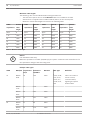
1
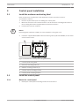
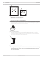
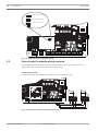
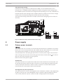
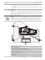
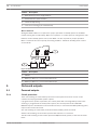
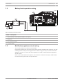
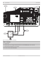
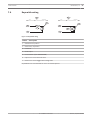
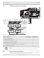
Control Panels
B5512/B4512
en
UL Installation Instructions
Control Panels
Table of Contents | en
3
Table of contents
1
Introduction
4
1.1
About documentation
4
1.1.1
Related documentation
4
1.2
Bosch Security Systems, Inc. product manufacturing dates
5
2
System overview
6
3
Control panel installation
7
3.1
Install the enclosure and wiring label
7
3.2
Install the control panel
7
3.2.1
Mount the control panel
7
3.2.2
Connect earth ground
9
3.2.3
Configure OUTPUT A using the jumper
3.3
Control panel to module wiring overview
10
4
Power supply
11
4.1
Primary power terminals
11
4.1.1
Install the transformer
12
4.2
Secondary (DC) power terminals
12
4.2.1
Install the battery
12
4.2.2
Battery maintenance
14
4.2.3
Battery supervision
14
4.2.4
Battery discharge and recharge schedule
14
4.3
B520 Auxiliary Power Supply
15
4.3.1
SDI2 address settings
15
4.3.2
Supervision
15
4.3.3
Auxiliary power supply trouble conditions
15
4.3.4
Installation and control panel wiring (B520)
16
4.3.5
Powered device and battery wiring
17
5
On-board outputs
18
5.1
Powered outputs
18
5.1.1
Circuit protection
18
5.1.2
Total available power
19
5.2
Open collector outputs
19
6
Control panel board overview
20
7
System wiring diagrams
21
7.1
System wiring overview
21
7.2
Battery lead supervision wiring
23
7.3
Notification appliance circuit wiring
23
7.4
Keyswitch wiring
25
7.5
SDI2 devices general system wiring
26
7.5.1
SDI2 bus wiring recommendations
26
7.6
Wiring label
30
8
Specifications
31
8.1
Wire requirements
32
UL Installation Instructions
9
2013.01 | 04 | F01U265448
4
en | Introduction
Control Panels
1
Introduction
1.1
About documentation
This document contains instructions for a trained installer to properly install, configure, and
operate this control panel, and all optional peripheral devices. Review this document before
beginning the installation to determine the hardware and wiring requirements for the features
used.
Throughout this document, the words “control panel” refer to both control panels (B5512 and
B4512).
Notifications
This document uses Notices, Cautions, and Warnings to draw your attention to important
information.
i
Notice!
These are important notes for successful operation and programming of equipment.
Caution!
!
These caution you that physical damage to the program and/or equipment might occur if you
do not follow the instructions.
Warning!
These warn you of an increased risk of physical damage to the equipment or to you if you do
not follow the instructions
Copyright
This document is the intellectual property of Bosch Security Systems, Inc. and is protected by
copyright. All rights reserved.
Trademarks
All hardware and software product names used in this document are likely to be registered
trademarks and must be treated accordingly.
1.1.1
Related documentation
To obtain any of the documents listed in this section, download them from the web.
Downloading documentation:
1.
Go to the Bosch Web site (http://www.boschsecurity.us/en-us/).
2.
Under Online Catalogs, click Online Product Catalogs.
3.
Under Product Categories, click Intrusion Alarm Systems.
4.
Under Search on the right side, click in the Product Search text box.
5.
Enter the CTN for the product for which you wish to download the documentation.
6.
Click Start search.
2013.01 | 04 | F01U265448
UL Installation Instructions
Control Panels
Introduction | en
7.
5
Under Search Results, click the desired product. The product page opens with the
Documents tab selected.
8.
Click en to the right of the desired document.
Call Bosch Security Systems, Inc., Technical Support (1-800-289-0096) if you need additional
assistance.
Control panel documents
Control Panels (B5512/B4512) Release Notes (P/N: F01U265447)*
Control Panels (B5512/B4512) Installation and System Reference Guide (P/N: F01U265444)+
Control Panels (B5512/B4512) Owner’s Manual (P/N: F01U265453) *
+
Control Panels (B5512/B4512) Program Entry Guide (P/N: F01U265465)+
Control Panels (B5512/B4512) UL Installation Guide (this document) (P/N: F01U265448)*
+
Control Panels (B5512/B4512) SIA Quick Reference Guide (P/N: F01U265466)* +
*Shipped with the control panel. +Located on the documentation CD shipped with the
control panel.
Keypad documents
Two-line Alphanumeric Keypad (B920) Installation Guide (P/N: F01U265450)*
ATM Style Alphanumeric Keypad (B930) Installation Guide (P/N: F01U265451)*
*Shipped with the keypad.
Optional module documents
Octo-input Module (B208) Installation and Operation Guide (P/N: F01U265456)*
Octo-output Module (B308) Installation and Operation Guide (P/N: F01U265458)*
Ethernet Communication Module (B426) Installation and Operation Guide (P/N: F01U266226)*
+
Plug-in Telephone Communicator (B430) Installation Guide Installation Guide (P/N:
F01U265454)*
Conettix Plug-in Cellular Communicator (B440) Installation and Operation Guide (P/N:
F01U265455)*
Auxiliary Power Supply (B520) Installation and Operation Guide (P/N: F01U265445)*
RADION receiver SD (B810) Installation Guide (P/N: F01U261834)*
SDI2 Inovonics Interface Module (B820) Installation Guide (P/N: F01U265460)*
*Shipped with the module. +Located on the documentation CD shipped with the module.
1.2
Bosch Security Systems, Inc. product manufacturing dates
Use the serial number located on the product label and refer to the Bosch Security Systems,
Inc. web site at http://www.boschsecurity.com/datecodes/.
The following image shows an example of a product label and highlights where to find the
manufacturing date within the serial number.
UL Installation Instructions
2013.01 | 04 | F01U265448
6
2
en | Introduction
Control Panels
System overview
B920/B930
Use Two-line Alphanumeric and
ATM Style Alphanumeric keypads
to operate the control panel by area.
B5512 control panels support up to 4 areas.
B4512 control panels support up to 2 areas.
Each area can have its own account number
or you can group together areas
with a common account number.
B208
Octo-input modules allow
the addition of up to 8
input devices.
B810
RADION receiver SDs
connect RADION wireless devices
to the control panel.
B820
SDI2 Inovonics Interface modules
interface with an Inovonics
wireless receiver.
B308
Octo-output modules allow
the addition of up to 8
output devices.
Control
Panel
On-Board Points
1 to 8
B520
Auxiliary Power Supply modules
expand power by connecting to
an SDI2 device bus or
other 12 volt devices.
2013.01 | 04 | F01U265448
B430
Plug-in Tephone Communicator
provides a single
telephone RJ-45 connector
to allow communication
over telephone lines.
B44x
Conettix Plug-In Cellular
Communicator allows
communciation over
a cellular network.
UL Installation Instructions
Control Panels
Introduction | en
3
Control panel installation
3.1
Install the enclosure and wiring label
7
Refer to Enclosures to determine if the application requires a specific enclosure.
To install the enclosure:
1.
Remove any knockouts prior to installing the control panel.
2.
Mount the enclosure in the desired location. Use all enclosure mounting holes. Refer to
the mounting instructions supplied with the selected enclosure.
3.
i
Pull the wires into the enclosure.
Notice!
Electromagnetic interference (EMI) can cause problems on long wire runs.
4.
Install the supplied B5512/B4512 Enclosure Wiring Label (P/N: F01U265449) on the inside
of the enclosure door.
1
2
3
2
3
4
2
5
2
Figure 3.1: Enclosure and control panel mounting (B10 shown)
1 ᅳ Control panel wiring label
2 ᅳ Enclosure mounting holes (4)
3 ᅳ Module mounting locations (4)
4 ᅳ Tamper switch mounting location
5 ᅳ Control panel mounting location
3.2
Install the control panel
3.2.1
Mount the control panel
1.
Identify the control panel mounting location in the enclosure.
UL Installation Instructions
2013.01 | 04 | F01U265448
8
en | Introduction
Control Panels
Figure 3.2: B10 and B11 control panel placement locations
1 ᅳ B10 Medium Control Panel Enclosure
2 ᅳ B11 Small Control Panel Enclosure
3 ᅳ Mounting clip locations for the B5512/B4512
2.
Snap the four supplied plastic standoffs onto four enclosure support posts. If using the
B12 Mounting Plate for D8103 Enclosure, attach the standoffs to the plate support posts.
Do not attach the standoffs with screws at this time.
Figure 3.3: Standoff attachment
3.
Place the control panel on top of the standoffs. Align the holes in the corners of the
control panel with the openings at the top of each standoff. Secure the control panel to
the standoffs with supplied, self-threading screws.
Figure 3.4: Mount control panel on standoffs
4.
If using the B12 Mounting Plate for D8103 Enclosure, rest the hook tabs on the mounting
plate hooks within the enclosure. Secure the lock-down tab to the plate mounting hole
with the screw provided.
2013.01 | 04 | F01U265448
UL Installation Instructions
Control Panels
3.2.2
Introduction | en
9
Connect earth ground
To help prevent damage from electrostatic discharges or other transient electrical surges,
connect the system to earth ground at the earth ground terminal before making other
connections. The
icon indicates the earth ground terminal. Use a recommended earth
ground reference, such as a grounding rod or a cold water pipe.
Notice!
i
Do not use telephone or electrical ground for the earth ground connection. Use 14 AWG (1.8
mm) to 16 AWG (1.5 mm) wire when making the connection. Do not connect other control
panel terminals to earth ground.
Caution!
!
3.2.3
Avoid electrostatic discharge. Always touch the earth ground connection with the
icon first,
before beginning work on the control panel.
Configure OUTPUT A using the jumper
When planning your installation, carefully consider the use of OUTPUT A. OUTPUT A is a form
C relay. You can configure the common terminal (C) of Output A (OUTPUT A) using the
jumper:
–
To provide +12 VDC (AUX power)
–
To be a COM terminal (parallel to all COM terminals)
–
To be a dry contact (no voltage, not common)
The control panel ships with the jumper in the default position, AUX power. (OUTPUT A, ‘C’
terminal using AUX PWR). Remove the door covering the jumper pins, and then move the
jumper to the left two pins for switched low (OUTPUT A parallel to COM terminals). Replace
the cover door. The OUTPUT A LED lights when OUTPUT A is active. Refer to the figure below
or to the B5512/B4512 Enclosure Wiring Label (P/N: F01U265442) to set the OUTPUT A
jumper.
UL Installation Instructions
2013.01 | 04 | F01U265448
10
en | Introduction
Control Panels
OUTPUT A (C terminal) = AUX PWR
P1
COM AUX
OUTPUT A (C terminal) = COM
P1
COM AUX
OUTPUT A (C terminal) = DRY
P1
COM AUX
COMMUNICATION MODULE 1
ETHERNET
ETHERNET
100BASE-T
LINK
USB
RESET
P1
ON-BOARD POINTS
Voltage Ranges
Open
3.7 - 5.0 VDC
Normal 2.0 - 3.0 VDC
Short
0.0 - 13 VDC
1k
AUX
OUTPUT A - 12 V +
18 VAC
18VAC
NO C NC COM AUX R Y
PWR A
OUTPUT A
+ BAT -
G B
B COM
C
OUTPUT
B
End of Line Resistors
1 COM 2 3 COM 4
5 COM 6
7 COM 8
1
5
7
COM
2
3
COM
4
COM
6
COM
TMPR
SDI2
Device Bus
R Y G B
C
B
OUTPUT
COM AUX
8
Figure 3.5: OUTPUT A jumper configuration options
3.3
Control panel to module wiring overview
In the following sections, this document provides instructions for wiring devices to your
control panel. You can use interconnect or terminal wiring.
Using terminal wiring
For terminal wiring, use 18 AWG to 22 AWG (1.02 mm to 0.65 mm) wire.
COMMUNICATION MODULE 1
ETHERNET
ETHERNET
100BASE-T
LINK
OUTPUT A
Jumper Under Cover
1k
18 VAC
18VAC
BATTERY
+ BAT -
AUX
OUTPUT A - 12 V +
NO C NC COM AUX R Y
PWR A
OUTPUT A
G B
B COM
C
OUTPUT
B
End of Line Resistors
1 COM 2 3 COM 4
5 COM 6
7 COM 8
1
5
7
COM
2
3
COM
4
COM
6
Figure 3.6: SDI2 devices daisy chained with terminal wiring
2013.01 | 04 | F01U265448
UL Installation Instructions
COM
8
C
B
OUTPUT
ON-BOARD POINTS
Voltage Ranges
Open
3.7 - 5.0 VDC
Normal 2.0 - 3.0 VDC
Short
0.0 - 13 VDC
TMPR
SDI2
Device Bus
R Y G B
OUTPUT A
RESET
USB
AUX PWR
COM
DRY
PWR
A
B
COM
PWR
A
B
COM
Control Panels
Introduction | en
11
Using interconnect wiring
Interconnect wiring connectors parallel the SDI2 PWR, A, B, and COM terminals on the
terminal strip. In installations with multiple SDI2 modules, using interconnect wiring makes
the installation quicker and easier than using terminal strip wiring. You use any combination of
terminal and interconnect wiring to wire multiple modules in parallel, but do not wire a single
module to the control panel using both terminal and interconnect wiring.
The interconnect wiring connectors are "keyed" (interconnect wiring plug can fit in only one
direction).
COMMUNICATION MODULE 1
ETHERNET
ETHERNET
100BASE-T
LINK
OUTPUT A
Jumper Under Cover
1k
18 VAC
18VAC
BATTERY
+ BAT -
AUX
OUTPUT A - 12 V +
NO C NC COM AUX R Y
PWR A
OUTPUT A
G B
B COM
C
OUTPUT
B
End of Line Resistors
1 COM 2 3 COM 4
5 COM 6
7 COM 8
1
5
7
COM
2
3
COM
4
COM
6
COM
C
B
OUTPUT
ON-BOARD POINTS
Voltage Ranges
Open
3.7 - 5.0 VDC
Normal 2.0 - 3.0 VDC
Short
0.0 - 13 VDC
TMPR
SDI2
Device Bus
R Y G B
OUTPUT A
RESET
USB
AUX PWR
COM
DRY
8
PWR
A
B
COM
PWR
A
B
COM
Figure 3.7: SDI2 devices daisy chained with interconnect wiring
4
Power supply
4.1
Primary power terminals
The control panel uses an 18 VAC, 22 VA internally fused transformer (CX4010) for its primary
power source. The control panel draws 125 mA when idle and 155 mA when in an alarm state.
The auxiliary power available for continuously powered devices is 800 mA.
Transient suppressors and spark gaps protect the circuit from power surges. This protection
relies on the ground connection at the earth ground terminal, marked with the
icon. Ensure
that you connect the terminal to a proper ground.
Refer to Connect earth ground, page 9.
AC power fail
The system indicates an AC power failure when the 18 VAC terminals do not have power. The
AC Fail Time parameter sets the number of minutes or seconds without AC power before the
control panel reports the failure, and the number of minutes or seconds after the power
returns before the control panel reports restored power.
Self diagnostics at power up and reset
The system performs a series of self-diagnostic tests of hardware, software, and programming
at power up and at reset. The self-diagnostics tests complete in approximately 10 to 30 sec.
If the control panel fails any test, a System Trouble message appears at the keypads.
UL Installation Instructions
2013.01 | 04 | F01U265448
12
en | Introduction
Control Panels
Install the transformer
4.1.1
Caution!
!
Do not short-circuit the terminals of the transformer: Shorting the terminals opens the internal fuse, causing permanent failure. Connect the transformer to the 18 VAC terminals of the
control panel before plugging it into the power source.
Notice!
i
Plan ahead
Route telephone, SDI2 bus wiring, and sensor loop wiring away from any AC conductors, including the transformer wire. AC wiring can induce noise and low level voltage into adjacent
wiring.
1.
Use 18 AWG (1.02 mm) wire minimum (12 AWG [2 mm] maximum) and connect the
transformer to the control panel. Make the wire length as short as possible. Do not
exceed 50 ft (15 m).
i
2.
Connect the wire to the control panel.
3.
Connect the wire to the transformer.
4.
Plug the transformer into an unswitched, 120 VAC, 60 Hz power outlet only.
5.
Secure the transformer to the outlet with the screw provided.
Notice!
The transformer screw is not present on the Canadian (cUL) transformer.
Secondary (DC) power terminals
4.2
A 12 V sealed lead-acid rechargeable battery (D126/D1218) supplies secondary power for
auxiliary and alarm outputs, and powers the system during interruptions in primary (AC)
power.
i
Notice!
Use Lead Acid Batteries Only: The charging circuit is calibrated for lead-acid batteries. Do not
use gel-cell or nicad batteries.
Extra batteries increase back-up time
To increase battery back-up time, connect a second 12 V battery in parallel to the first battery.
Use a D122 Dual Battery Harness to ensure proper and safe connection.
Refer to Standby battery calculations.
D1218 Battery
The D1218 is a 12 V, 18 Ah battery for use in applications requiring extended battery standby
time. The control panel does not support more than 18 Ah.
4.2.1
Install the battery
1.
Place the battery upright in the base of the enclosure.
2.
Locate the red and black leads supplied in the literature pack.
2013.01 | 04 | F01U265448
UL Installation Instructions
Control Panels
Introduction | en
3.
13
Connect the black battery lead to the BAT- terminal, and then to the negative (-) side of
the battery.
4.
Connect the red battery lead to the BAT+ terminal, and then to the positive (+) side of the
battery.
Warning!
High current arcs are possible. The positive (red) battery lead and the BAT+ terminal can create high current arcs if shorted to other terminals or the enclosure. Use caution when working
with the positive lead and BAT+. Always disconnect the positive (red) lead from the battery
before removing it from BAT+.
Caution!
maintained between the battery terminals, battery wiring, and all other wiring. Battery wiring
cannot share the same conduit, conduit fittings, or conduit knockouts with other wiring.
COMMUNICATION MODULE 1
ETHERNET
ETHERNET
100BASE-T
2
LINK
OUTPUT A
Jumper Under Cover
SDI2
Device Bus
R Y G B
ON-BOARD POINTS
Voltage Ranges
Open
3.7 - 5.0 VDC
Normal 2.0 - 3.0 VDC
Short
0.0 - 13 VDC
1k
18 VAC
18VAC
1
3
BATTERY
+ BAT -
AUX
OUTPUT A - 12 V +
NO C NC COM AUX R Y
PWR A
OUTPUT A
5
G B
B COM
C
OUTPUT
B
End of Line Resistors
1 COM 2 3 COM 4
5 COM 6
7 COM 8
1
5
7
COM
2
3
COM
4
COM
6
COM
C
B
OUTPUT
OUTPUT A
RESET
USB
AUX PWR
COM
DRY
TMPR
!
The battery terminals and wire are not power limited. A 0.250 in (6.4 mm) space must be
8
4
7
6
Figure 4.1: Non-power-limited wiring
Callout ᅳ Description
1 ᅳ Conduit required for use with external batteries
2 ᅳ To CX4010 UL Listed Class 2 Transformer 18 VAC 22 VA 60 Hz
3 ᅳ 0.25 in (6.4 mm) minimum
4 ᅳ Battery terminals. BAT- is non-power limited
5 ᅳ Battery wires
UL Installation Instructions
2013.01 | 04 | F01U265448
14
en | Introduction
Control Panels
Callout ᅳ Description
6 ᅳ 12 V sealed lead-acid rechargeable battery (D126/D1218)
7 ᅳ Sensor loop wires
Charge the battery
Connect the battery and then the transformer to allow the control panel to charge the battery
while you complete the installation.
Battery maintenance
4.2.2
Use sealed lead-acid rechargeable battery (12.0 VDC, 7 Ah or 12.0 VDC, 18 Ah). The control
panel supports up to 18 Ah of battery. If you use two D126 (12.0 VDC, 7 Ah) batteries, then
connect them using the D122/D122L Dual Battery Harness. If you install two batteries, they
must have the same capacity.
Replace the batteries every 3 to 5 years. If you install two batteries, replace them both at the
same time.
Record the date of installation directly on the battery.
Caution!
!
Exceeding the maximum output ratings or installing the transformer in an outlet that is routinely switched off causes heavy discharges. Routine heavy discharges can lead to premature
battery failure.
4.2.3
Battery supervision
The battery charging float level occurs at 13.65 VDC. If the battery voltage drops below 12.1
VDC, the control panel sends a LOW BATTERY report, if programmed to do so.
When the battery voltage drops to 10.2 VDC, the keypad or keypads show low battery
messages. The control panel (if programmed for power supervision) sends a Battery Low
report in the Modem4 communication format. It sends a Low System Battery (302) report in
the Contact ID format.
If programmed for power supervision, the control panel adds a missing battery event to the
event log. If programmed for battery fault reports, the control panel sends a BATTERY
MISSING report in the Modem4 communication format, or Control Panel Battery Missing (311)
report in the Contact ID format.
When battery voltage returns to 13.4 V, the keypads stop showing the low battery messages. If
the control panel is programmed for power supervision, it sends a BATTERY RESTORAL report
in the Modem4 communication format or a Control Panel Battery Restored to Normal (302)
report in the Contact ID format.
Investigate LOW BATTERY events immediately: If primary (AC) power is off and the discharge
continues, the control panel becomes inoperative when the battery voltage drops below 10.2
VDC.
4.2.4
Battery discharge and recharge schedule
Discharge cycle
13.65 VDC - Charging float level.
12.1 VDC - Low Battery Report, if programmed.
10.2 VDC - Minimum operational voltage.
2013.01 | 04 | F01U265448
UL Installation Instructions
Control Panels
Introduction | en
15
Recharge cycle
AC ON - Battery charging begins and AC Restoral Reports sent.
13.4 V - Battery Restoral Report sent. Battery float charged.
Further information
Refer to Powered outputs, page 18.
B520 Auxiliary Power Supply
4.3
The optional B520 Auxiliary Power Supply Module provides up to 2 A of 12 VDC standby
power for Fire and Burglar applications. For Burglar applications, an additional 2 A of alarm
power is available, allowing 2 A of standby current and up to 4 A of alarm current. You can
connect more than one module to the control panel.
The B5512 control panel supports up to 4 modules, while the B4512 supports up to 2
modules.
Connect B520 Auxiliary Power Supply Modules to the SDI2 bus on the control panel using
terminals PWR, A, B, and COM. This section includes basic installation instructions. Refer to
the Auxiliary Power Supply Module (B520) Installation Guide (P/N: F01U215240) for complete
installation instructions and for the B520 Auxiliary Power Supply Module Battery Standby Chart
for battery standby time calculations.
SDI2 address settings
4.3.1
Notice!
i
The module reads the address switch setting only during power up. If you change the
switches after you apply power to the module, you must cycle the power to the module in order for the new setting to be enabled.
For single-digit address numbers 1 to 9, set the tens switch to 0 and the ones digit to the
appropriate number. If multiple B520 modules reside on the same system, each B520 module
must have a unique address.
TENS
ONES
Figure 4.2: Address switches set to 2
4.3.2
Supervision
The control panel supervises B520 Auxiliary Power Supply Modules on the SDI2 bus.
With any failure to receive an expected response from an SDI2 module, all keypads show in a
system fault display. The control panel sends a module trouble report to the central station (if
configured for module trouble reports).
4.3.3
Auxiliary power supply trouble conditions
Each auxiliary power supply module on the SDI2 bus monitors several conditions including AC
status, battery status, over current status, and a tamper input. Each of these conditions
produces a unique system trouble condition at all keypads. The control panel sends a module
trouble report to the central station (if configured for module trouble reports).
When the control panel shows a generic trouble condition for a SDI2 bus power supply
module, it could mean one of several non-serviceable things has occurred; low power output,
module firmware flash error, or battery charger circuit failure.
UL Installation Instructions
2013.01 | 04 | F01U265448
16
en | Introduction
4.3.4
Control Panels
Installation and control panel wiring (B520)
The power supply draws approximately 15 mA (+/- 1 mA) from the control panel.
Ensure that there is enough power for the module and other powered devices you want
connected to the system.
Refer to On-board outputs, page 18.
Caution!
!
Always power down the control panel and B520 when connecting modules, relays, or other
wiring. Power down the control panel and the B520 by unplugging their transformers and disconnecting their batteries.
Install the module
1.
Install the enclosure on the wall using the instructions supplied with the enclosure.
2.
Set the module address using the address switches before you install it in the enclosure.
3.
Insert the plastic mounting clips onto the appropriate standoff locations inside the
enclosure or on a mounting skirt, when required.
4.
Mount the module onto the plastic mounting clips and then secure it using the supplied
mounting screws.
Wire to earth ground
To help prevent damage from electrostatic charges or other transient electrical surges,
connect the system to earth ground before making other connections. Recommended earth
ground references are a grounding rod or a cold water pipe. When grounding, run wire as
close as possible to grounding device.
Caution!
!
Do not use telephone or electrical ground for the earth ground connection. Use 14 AWG (1.8
mm) to 16 AWG (1.5 mm) wire when making the connection.
Figure 4.3: B520 earth ground wiring
Callout ᅳ Description
1 ᅳ Power supply module
2 ᅳ 14 AWG - 16 AWG (1.8 mm - 1.5 mm) wire
3 ᅳ Ground device (grounding rod or cold water pipe)
2013.01 | 04 | F01U265448
UL Installation Instructions
Control Panels
Introduction | en
17
Wire to the control panel
When wiring a module to a control panel, use the terminal strip labeled with PWR, A, B, and
COM for SDI2 IN to wire to terminals labeled PWR, A, B, and COM on the control panel.
Use 12 AWG to 22 AWG (2 mm to 0.65 mm) wire.
SDI2 OUT
SDI2 IN
1k
AUX
- 12 V +
COM AUX
PWR A B COM
PWR A B COM
R Y
PWR A
G B
B COM
C
OUTPUT
B
End of Line Resistors
1 COM 2 3 COM 4
5 COM 6
7 COM 8
1
5
7
COM
2
3
COM
4
COM
6
COM
C
B
OUTPUT
2
ON-BOARD POINTS
Voltage Ranges
Open
3.7 - 5.0 VDC
Normal 2.0 - 3.0 VDC
Short
0.0 - 13 VDC
TMPR
SDI2
Device Bus
R Y G B
RESET
1
8
3
R
Y
G
B
Figure 4.4: B520 to the control panel wiring
Callout ᅳ Description
1 ᅳ Control panel
2 ᅳ Power supply module
3 ᅳ Terminal strip wiring
4.3.5
Powered device and battery wiring
Wire to SDI2 powered devices
When wiring the output of a B520 to a SDI2 module, you can use either the SDI2 OUT terminal
strip labeled with PWR, A, B, and COM to wire to terminals labeled PWR, A, B, and COM on
the next module, or you can use the interconnect wiring connector (included). Wiring the
output of a B520 to a SDI2 device provides power to the device while passing through data
between the control panel and the device.
1
SDI2 OUT
SDI2 IN
PWR A B COM
PWR A B COM
1
SDI2 OUT
SDI2 IN
PWR A B COM
PWR A B COM
R YGB
3
4
2
2
PWR A B COM
PWR A B COM
Figure 4.5: B520 to powered devices - terminal strip or interconnect wiring connector
UL Installation Instructions
2013.01 | 04 | F01U265448
18
en | Introduction
Control Panels
Callout ᅳ Description
1 ᅳ B520 Auxiliary Power Supply Module
2 ᅳ Powered device (SDI2 module)
3 ᅳ Terminal strip wiring
4 ᅳ Interconnect wiring (P/N: F01U079745)
Wire to batteries
Wiring the B520 to BATT 1 is required for proper operation of standby power for the B520
module. Wiring the second battery (BATT 2) is optional. If a control panel is configured for two
batteries as the standby power source, then BATT 2 is also required for proper operation.
BATT 2 must have the same capacity and rating as BATT 1. Maximum standby power cannot
exceed 36 Ah.
1
BATT
R
1
+
-
B
BATT
R
2
+
-
B
3
2
Figure 4.6: B520 BATT terminals wiring
Callout ᅳ Description
1 ᅳ Module
2 ᅳ Battery 2 (BATT 2) - (12 V nominal lead acid)
3 ᅳ Battery 1 (BATT 1) - (12 V nominal lead acid))
5
On-board outputs
5.1
Powered outputs
5.1.1
Circuit protection
Three self-resetting circuit breakers protect the control panel from short circuits on the
continuous and programmable power outputs.
If programmed for power supervision, the control panel adds a missing battery event to the
event log. If programmed for battery fault reports, the control panel sends a BATTERY
MISSING report in the Modem4 communication format, or Control Panel Battery Missing (311)
report in the Contact ID format.
One self-resetting circuit breaker protects the AUX (auxiliary power) terminal.
Another self-resetting circuit breaker protects the OUTPUT A’s C terminal.
The third self-resetting circuit breaker protects PWR/R terminal (power) of the SDI2 terminal
block.
2013.01 | 04 | F01U265448
UL Installation Instructions
Control Panels
i
5.1.2
Introduction | en
19
Notice!
UL requires any device powered from a power output to be supervised.
Total available power
The control panel produces up to 800 mA of combined power at 12.0 VDC nominal to power
peripheral devices. The outputs listed below and OUTPUT A share the available power.
AUX terminal (auxiliary power)
AUX
Powers devices requiring continuous power (for example, motion detectors).
R/PWR terminal and power output of the interconnect connector (SDI2 power)
R
PWR
Power SDI2 devices such as a B208 Octo-input Module, a B308 Octo-output Module, or B920/
B930 keypads.
Plug-in module connector
Connect plug-in modules such as the B440 Conettix Plug-in Cellular Communicator.
OUTPUT A
NO C NC
OUTPUT A
Output A can be configured as a dry contact (contact rating is 3 Amps), switched common
(sink current), or a powered output. As a powered output, it can provide alarm power or
switched auxiliary power. The default configuration for Output A makes it a powered output
providing alarm power. Use OUTPUT PARAMETERS in RPS to configure programmable
outputs.
Refer to Configure OUTPUT A using the jumper, page 9.
5.2
Open collector outputs
OUTPUT B and C
B
C
OUTPUT
Outputs B and C are open collector outputs that can sink up to 50 mA of power (+12 VDC),
when activated.
As an example, the figure below shows using Outputs B and C to trigger the relays of a D134
Dual Relay Module.
UL Installation Instructions
2013.01 | 04 | F01U265448
en | Introduction
Control Panels
1
COMMUNICATION MODULE 1
ETHERNET
100BASE-T
ETHERNET
20
LINK
OUTPUT A
Jumper Under Cover
USB
1k
AUX
OUTPUT A - 12 V +
BATTERY
C
OUTPUT
B
End of Line Resistors
1 COM 2 3 COM 4
5 COM 6
7 COM 8
C
B
OUTPUT
ON-BOARD POINTS
Voltage Ranges
Open
3.7 - 5.0 VDC
Normal 2.0 - 3.0 VDC
Short
0.0 - 13 VDC
TMPR
SDI2
Device Bus
R Y G B
OUTPUT A
RESET
N/O 1
AUX PWR
COM
DRY
18 VAC
2
COMM 1
N/C 1
X1 X1 +
N/O 2
COMM 2
N/C 2
18VAC
NO C NC COM AUX R Y
PWR A
OUTPUT A
+ BAT -
G B
B COM
1
COM
2
3
COM
4
5
COM
6
7
COM
8
X2 X2 +
Figure 5.1: OUTPUT B and C wiring
Callout ᅳ Description
1 ᅳ Control panel
2 ᅳ D134 Dual Relay Module
Use OUTPUT PARAMETERS in RPS to configure programmable outputs.
6
Control panel board overview
2
1
4
3
5
6
MODULE 1
7
Y
X
MODULE
RELEASE
COMMUNICATION MODULE 1
ETHERNET
ETHERNET
100BASE-T
OUTPUT A
Jumper Under Cover
USB
1k
BATTERY
AUX
OUTPUT A - 12 V +
C
OUTPUT
B
End of Line Resistors
1 COM 2 3 COM 4
5 COM 6
7 COM 8
1
5
7
C
B
OUTPUT
ON-BOARD POINTS
Voltage Ranges
Open
3.7 - 5.0 VDC
Normal 2.0 - 3.0 VDC
Short
0.0 - 13 VDC
TMPR
SDI2
Device Bus
R Y G B
OUTPUT A
RESET
10
AUX PWR
COM
DRY
18 VAC
8
9
LINK
11
12
13
14
18VAC
20
+ BAT -
19
NO C NC COM AUX R Y
PWR A
OUTPUT A
18
17
G B
B COM
COM
2
3
16
COM
4
COM
6
COM
8
15
Figure 6.1: Control panel board overview
Callout ᅳ Description
Callout ᅳ Description
1 ᅳ Jumper cover. Remove to configure
11 ᅳ RESET button
Output A
2013.01 | 04 | F01U265448
2 ᅳ OUTPUT A LED
12 ᅳ Terminals for Output B and Output C
3 ᅳ Holes to stabilize plug-on modules
13 ᅳ Tamper switch connector
4 ᅳ Plug-in module connector
14 ᅳ SDI2 interconnect wiring connector
5 ᅳ Green 100Mb LED
15 ᅳ Sensor loop terminals for points 1 to 8
UL Installation Instructions
Control Panels
Introduction | en
Callout ᅳ Description
Callout ᅳ Description
6 ᅳ Yellow LINK LED
16 ᅳ SDI2 terminals (power and data)
7 ᅳ Plug-in module retention clip
17 ᅳ Auxiliary power terminals
8 ᅳ On-board Ethernet connector
18 ᅳ Terminals for Output A
9 ᅳ USB connector
19 ᅳ Battery terminals
10 ᅳ Heartbeat LED (blue)
20 ᅳ 18 VAC power input terminals
7
System wiring diagrams
7.1
System wiring overview
21
Notice!
For UL Certificated accounts, additional power can be obtained using only a UL Listed auxiliary 12.0 VDC regulated, power-limited power supply, such as the B520 Auxiliary Power Sup-
i
ply Module.
All terminals are power limited except BAT+ (battery positive).
All terminals are supervised except OUTPUT A, OUTPUT B, and OUTPUT C.
For proper supervision, do not loop wire under terminals. Break the wire run to provide supervision of connections.
UL Installation Instructions
2013.01 | 04 | F01U265448
22
en | Introduction
Control Panels
MODULE 1
Y
X
MODULE
RELEASE
COMMUNICATION MODULE 1
ETHERNET
ETHERNET
100BASE-T
1
14
LINK
OUTPUT A
Jumper Under Cover
ON-BOARD POINTS
Voltage Ranges
Open
3.7 - 5.0 VDC
Normal 2.0 - 3.0 VDC
Short
0.0 - 13 VDC
1k
18 VAC
BATTERY
18VAC
2
+ BAT -
AUX
OUTPUT A - 12 V +
NO C NC COM AUX R Y
PWR A
OUTPUT A
G B
B COM
RESET
SDI2
Device Bus
R Y G B
11
C
OUTPUT
B
End of Line Resistors
1 COM 2 3 COM 4
5 COM 6
7 COM 8
1
5
7
COM
2
3
C
B
OUTPUT
OUTPUT A
12
COM
4
COM
6
COM
TMPR
AUX PWR
COM
DRY
13
USB
N/O 1
COMM
N/C 1
X1 X1 +
10
8
9
3
6
4
8
7
+
EOL
5
Figure 7.1: System wiring overview
Callout ᅳ Description
Callout ᅳ Description
1 ᅳ Control panel
8 ᅳ SDI2 wiring
2 ᅳ CX4010 UL Listed Class 2 Transformer 18 VAC
9 ᅳ Supervised sensor loops, points 1 to 8 (Initiating
22 VA 60 Hz
Device Circuits)
3 ᅳ To earth ground
10 ᅳ To ICP-EZTS Tamper Switch
4 ᅳ D122/D122L Dual Battery Harness, as required
11 ᅳ Programmable outputs
5 ᅳ Batteries (Unsupervised)
12 ᅳ External relay
6 ᅳ Audible signaling device
13 ᅳ USB connector
7 ᅳ UL Listed four-wire smoke detectors with EOL
14 ᅳ RJ-45 modular jack for Ethernet
resistor
2013.01 | 04 | F01U265448
UL Installation Instructions
N/O 2
COMM
N/C 2
X2 X2 +
Control Panels
Introduction | en
7.2
23
Battery lead supervision wiring
COMMUNICATION MODULE 1
4
ETHERNET
ETHERNET
100BASE-T
LINK
OUTPUT A
Jumper Under Cover
OUTPUT A
BAT 2-
CHGR-
BAT 2+
VAUX+
BAT 1-
SUPV
BAT 1+
CHGR+
ON-BOARD POINTS
Voltage Ranges
Open
3.7 - 5.0 VDC
Normal 2.0 - 3.0 VDC
Short
0.0 - 13 VDC
1k
18 VAC
BATTERY
AUX
OUTPUT A - 12 V +
RESET
SDI2
Device Bus
R Y G B
C
OUTPUT
B
End of Line Resistors
1 COM 2 3 COM 4
5 COM 6
7 COM 8
1
5
7
C
B
OUTPUT
1
USB
TMPR
AUX PWR
COM
DRY
3
18VAC
+ BAT -
NO C NC COM AUX R Y
PWR A
OUTPUT A
G B
B COM
COM
2
3
COM
4
COM
6
COM
8
2
Figure 7.2: Battery supervision wiring
Callout ᅳ Description
1 ᅳ D113 Battery Lead Supervision Module, if required
2 ᅳ Batteries
3 ᅳ To supervision point
4 ᅳ Control panel
7.3
Notification appliance circuit wiring
The control panels do not have an onboard NAC.
Programming determines the format of the output and the conditions that activate it. One selfresetting circuit breaker protects against shorts. When using the relay to activate notification
appliance circuits in UL Listed fire alarm applications, install a D192G Notification Appliance
Circuit module.
Refer to the D192G Notification Appliance Circuit Module Installation Guide (P/N: 4998122260)
for detailed wiring information and specifications.
UL Installation Instructions
2013.01 | 04 | F01U265448
24
en | Introduction
Control Panels
1
2
COMMUNICATION MODULE 1
ETHERNET
ETHERNET
100BASE-T
LINK
USB
SDI2
Device Bus
R Y G B
ON-BOARD POINTS
Voltage Ranges
Open
3.7 - 5.0 VDC
Normal 2.0 - 3.0 VDC
Short
0.0 - 13 VDC
1k
AUX
OUTPUT A - 12 V +
18 VAC
18VAC
+ BAT -
NO C NC COM AUX R Y
PWR A
OUTPUT A
G B
B COM
C
OUTPUT
B
End of Line Resistors
1 COM 2 3 COM 4
5 COM 6
7 COM 8
1
5
7
COM
2
3
COM
4
COM
6
COM
4
AUX PWR
ALARM TRIG
3
COM
SUPV IN
ALARM CKT
Figure 7.3: Notification appliance circuit wiring
Callout ᅳ Description
1 ᅳ Control panel
2 ᅳ Output jumper set to configure OUTPUT A terminal C for AUX POWER (jumper cover removed)
3 ᅳ D192G Notification Appliance Circuit module
4 ᅳ 1k Ω EOL resistor (P/N: F01U033966)
2013.01 | 04 | F01U265448
UL Installation Instructions
8
TMPR
GND OUT
C
B
OUTPUT
RESET
P1
Control Panels
7.4
Introduction | en
25
Keyswitch wiring
2
1
6
7
3
3
5
5
4
4
Figure 7.4: Keyswitch wiring
Callout ᅳ Description
1 ᅳ Maintained keyswitch
2 ᅳ Momentary keyswitch
3 ᅳ Common
4 ᅳ Point input
5 ᅳ 1 kΩ resistor (P/N: 4998143839)
6 ᅳ Open on a circuit arms the area
7 ᅳ Short on a circuit toggles the arming state
Keyswitches are not intended for use in UL listed systems.
UL Installation Instructions
2013.01 | 04 | F01U265448
26
en | Introduction
7.5
Control Panels
SDI2 devices general system wiring
COMMUNICATION MODULE 1
ETHERNET
ETHERNET
100BASE-T
LINK
OUTPUT A
Jumper Under Cover
ON-BOARD POINTS
Voltage Ranges
Open
3.7 - 5.0 VDC
Normal 2.0 - 3.0 VDC
Short
0.0 - 13 VDC
1k
18 VAC
18VAC
1
1
2
2
4
5
6
6
BATTERY
AUX
OUTPUT A - 12 V +
NO C NC COM AUX R Y
PWR A
OUTPUT A
+ BAT -
G B
B COM
RESET
SDI2
Device Bus
R Y G B
C
OUTPUT
B
End of Line Resistors
1 COM 2 3 COM 4
5 COM 6
7 COM 8
1
5
7
COM
2
3
COM
4
COM
6
COM
C
B
OUTPUT
OUTPUT A
USB
TMPR
AUX PWR
COM
DRY
8
3
Figure 7.5: SDI2 devices system wiring
Callout ᅳ Description
B5512 Capacity
B4512 Capacity
1 ᅳ B208 Octo-input Module
4
2
2 ᅳ B308 Octo-output Module
5
3
3 ᅳ B426 Ethernet Communication Module
1
1
4 ᅳ B520 Auxiliary Power Supply Module
4
2
5 ᅳB810 wireless receiver or B820 SDI2 Inovonics Interface Module
1
1
6 ᅳ B920 Keypad or B930 Keypad
8
8
i
7.5.1
Notice!
The SDI2 power terminal (R/PWR) is power limited. The SDI2 terminals are supervised.
SDI2 bus wiring recommendations
Use the following SDI2 bus wiring recommendations for SDI2 installation. The control panel
and SDI2 modules use the SDI2 bus to communicate with one another.
2013.01 | 04 | F01U265448
UL Installation Instructions
Control Panels
Introduction | en
27
You can configure modules via home run, daisy chain, or single level T-tap anywhere on the
SDI2 bus.
1
COMMUNICATION MODULE 1
ETHERNET
ETHERNET
100BASE-T
LINK
OUTPUT A
Jumper Under Cover
ON-BOARD POINTS
Voltage Ranges
Open
3.7 - 5.0 VDC
Normal 2.0 - 3.0 VDC
Short
0.0 - 13 VDC
1k
18 VAC
BATTERY
18VAC
+ BAT -
AUX
OUTPUT A - 12 V +
NO C NC COM AUX R Y
PWR A
OUTPUT A
G B
B COM
C
OUTPUT
B
End of Line Resistors
1 COM 2 3 COM 4
5 COM 6
7 COM 8
1
5
7
COM
2
3
C
B
OUTPUT
SDI2
Device Bus
R Y G B
COM
4
COM
6
COM
TMPR
OUTPUT A
RESET
USB
AUX PWR
COM
DRY
8
3
2
2
2
2
2
2
2
4
5
2
2
2
2
2
Figure 7.6: SDI2 bus wiring recommendations
Callout ᅳ Description
1 ᅳ Control panel
2 ᅳ SDI2 device (module or keypad)
3 ᅳ Daisy chain wiring
4 ᅳ Single-level T-tapped wiring
5 ᅳ Home run wiring
Notice!
i
There can only be a difference of 2 volts (maximum) between the AUX power terminals of the
control panel or power supply and the device for the modules and keypads to work properly
under all conditions.
UL Installation Instructions
2013.01 | 04 | F01U265448
28
en | Introduction
Control Panels
Maximum cable lengths
The following rules must be followed when wiring the SDI2 bus.
–
The SDI2 bus requires the use of un-shielded cable from 12 AWG to 22 AWG.
–
SDI2 devices or keypads must be within 2000 ft (610 m) of the control panel.
–
Maximum overall cable lengths are listed in the following table:
Cable
Overall
Cable
Overall
Cable
Overall
Cable
Overall
capacitance
cable
capacitance
cable
capacitance
cable
capacitance
cable
length
length
length
length
pF/ft
ft
pF/ft
ft
pF/ft
ft
pFf/ft
ft
< 17
7500
22
6363
27
5185
32
4400
18
7500
23
6086
28
5000
33
4242
19
7350
24
5800
29
4828
34
4100
20
7000
25
5600
30
4700
35
4000
21
6666
26
5385
31
4516
36
3800
Table 7.1: Maximum cable length
Notice!
Use unshielded cable only.
i
Maximum capacitance of 140nF (140,000 pF) per system. Contact the wire manufacturer for
the capacitance ratings of the wire being used.
Example cable types
AWG
22
MFG/PN
Belden
Capacitance
Resistance
pF/ft
Ω/1000 ft
18
16.3
Max Run
NEC Type
Definition
7500
CL3P, CL3R,
Class 2 and Class 3
CL3, CL3X,
remote control,
CL2P, CL2,
communications,
CL2R, CL2X,
signaling and power
CM
limited cables
5541
Belden
15
17.6
7500
20
16.2
7000
19
15.7
7350
22
6.5
6363
15
17.6
7500
1242
Belden
5502
Belden
5522
18
Belden
5302
Belden
1242
2013.01 | 04 | F01U265448
UL Installation Instructions
Control Panels
AWG
Introduction | en
MFG/PN
16
Belden
Capacitance
Resistance
pF/ft
Ω/1000 ft
Max Run
19.9
4.0
7000
23.5
4.2
5800
32
1.56
4400
NEC Type
29
Definition
HC2758
Belden
5202
12
Belden
5002
Table 7.2: Maximum cable length
i
Notice!
Fire alarm applications require NEC cable type FPLR, FPLP, or FPL or the equivalent power
limited fire alarm cables (refer to article 760 of the NFPA 70 code).
UL Installation Instructions
2013.01 | 04 | F01U265448
30
7.6
en | Introduction
Control Panels
Wiring label
2013.01 | 04 | F01U265448
UL Installation Instructions
Control Panels
8
Introduction | en
31
Specifications
Control panel power supply specifications
Voltage Input (Power Primary
18 VAC
Supply)
terminals
18 VAC 22 VA Class 2 transformer (CX4010)
Secondary BAT terminals
12 Volt Sealed Lead Acid Rechargeable Battery (D126
or D1218)
Current
Control Panel: Idle 125 mA; Alarm 155 mA
Requirements
Refer to the Standby battery requirements and calculations section in the Control
Panels (B5512/B4512) Installation and System Reference Guide (P/N: F01U265444)
for the current draw requirements of other system components.
Power Outputs
All external connections are power-limited. The battery terminals are not power
limited.
SDI2 terminals and PWR/R and
800 mA for continuously powered devices.
interconnect
COM/B
Shared with AUX power terminal.
connector
terminals
Alarm power
OUTPUT A
1.3 A for Burglary applications. Output can be
output
terminal
steady or one of four pulsed patterns depending
on programming. Refer to Outputs in RPS Help or
the Control Panels (B5512/B4512) Program Entry
Guide (P/N: F01U265465).
Aux power
Fire and Fire/
AUX and
800 mA for continuously powered devices.
COM
Shared with SDI2 R/PWR terminal and
terminals
interconnect connector.
Alarm power output for OUTPUT A cannot exceed 500 mA.
Burglary Systems
Minimum Operating
10.2 VDC (The control panel might operate below this voltage, but it will cease to
Voltage
operate as an alarm panel.)
SDI2 Bus
12 VDC nominal (7500 ft combined length) maximum
Ethernet Connection
10BASE-T
100BASE-TX
Battery Discharge/
Discharge cycle
Recharge Schedule
13.65 VDC - Charging float level.
12.1 VDC - Low Battery Report, if programmed.
10.2 VDC - Minimum operational voltage.
Recharge Cycle
AC ON - Battery charging begins and AC Restoral Reports sent.
13.4 V - Battery Restoral Report sent. Battery float charged.
Environmental
Temperature
0℃ to +49℃ (+32℉ to 122℉)
Relative
5% to 93% at +32℃ (+90℉) non-condensing
Humidity
Arming Stations
B920 Two-line Alphanumeric Keypads, B930 ATM Style Alphanumeric Keypads
UL Installation Instructions
2013.01 | 04 | F01U265448
32
en | Introduction
Control Panels
Point Thresholds
On-board points
Open - 3.7 to 5.0 VDC
1 to 8
Normal - 2.0 to 3.0 VDC
Short - 0.0 to 1.3 VDC
Short circuit current - 5 mA
Compatible
B10 Medium Control Panel Enclosure, B11 Small Control Panel Enclosure, D2203
Enclosures
Enclosure, D8103 Universal Enclosure, D8108A Attack Resistant Enclosure, and
D8109 Fire Enclosure
8.1
Wire requirements
Terminal label
Terminal description
Requirements
18VAC
AC
18 AWG min (up to 12 AWG max)
Earth ground
16 AWG min (up to 14 AWG max)
Battery +
Bosch supplied wire lead, included with control
BAT +
panel.
BAT -
Battery -
Bosch supplied wire lead, included with control
panel.
OUTPUT A NO
Output A normally open
OUTPUT A C
Output A common
OUTPUT A NC
Output A normally closed
COM
Common
AUX
+ AUX power
PWR/R
SDI2 power
22 AWG min (up to 12 AWG max)
A/Y
SDI2 data bus A
22 AWG min (up to 12 AWG max)
B/G
SDI2 data bus B
22 AWG min (up to 12 AWG max)
COM/B
SDI2 common
22 AWG min (up to 12 AWG max)
1
Point 1
22 AWG min (up to 12 AWG max)
COM
Point 1/2 common
2
Point 2
3
Point 3
COM
Point 3/4 common
4
Point 4
5
Point 5
COM
Point 5/6 common
6
Point 6
7
Point 7
COM
Point 7/8 common
8
Point 8
2013.01 | 04 | F01U265448
22 AWG min (up to 12 AWG max)
UL Installation Instructions
Control Panels
Introduction | en
OUTPUT B
Output B
OUTPUT C
Output C
33
22 AWG min (up to 12 AWG max)
UL Installation Instructions
2013.01 | 04 | F01U265448
Bosch Security Systems, Inc.
130 Perinton Parkway
Fairport, NY 14450
USA
www.boschsecurity.com
© Bosch Security Systems, Inc., 2013