1
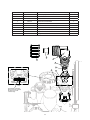
INSTALLATION AND OPERATING
INSTRUCTIONS
AQUA-PURE® CBF SERIES RESIDENTIAL
BACKWASH FILTRATION SYSTEMS
MODELS:
CBF100
CBF150
CBF200
Installer, please leave with homeowner.
Homeowner, retain for future reference.
INSTR2189 0611
SAFETY INFORMATION
Read, understand, and follow all safety information contained in these instructions prior to installation and use of the CBF Series Residential Backwash Filtration Systems. Retain these instructions for future reference. Failure to follow installation, operation and maintenance instructions may result in property damage and will void
warranty.
Intended use:
The CBF Series Residential Backwash Filtration Systems are intended for use in reducing certain undesirable contaminants in water in homes and have not
been evaluated for other uses. The systems must be installed indoors near the point of entry of a home water line, and be installed by a qualified professional
according to these installation instructions.
EXPLANATION OF SIGNAL WORD CONSEQUENCES
WARNING
CAUTION
CAUTION
Indicates a potentially hazardous situation, which, if not avoided, could result in death or serious injury and/or property damage.
Indicates a potentially hazardous situation, which, if not avoided, may result in minor or moderate injury and/or property damage.
Indicates a potentially hazardous situation, which, if not avoided, may result in property damage.
WARNING
To reduce the risk associated with choking:
• Do not allow children under 3 years of age to have access to small parts during the installation of this product.
To reduce the risk associated with ingestion of contaminants:
• Do not use with water that is microbiologically unsafe or of unknown quality without adequate disinfection before or after the system.
To reduce the risk of physical injury:
• Shut off inlet water supply and depressurize system as shown in manual prior to service.
To reduce the risk associated with a hazardous voltage:
• If the home electrical system requires use of the cold water system as an electrical safety ground, a jumper must be used to ensure a sufficient ground connection across the
Filtration System installation piping — refer installation to qualified personnel.
• Do not use the system if the power cord is damaged — contact qualified service personnel for repair.
To reduce the risk associated with back strain due to the heavy weight of the various system components:
• Follow safe lifting procedures.
CAUTION
To reduce the risk associated skin, eye, and respiratory tract irritation from gravel and filter media during installation:
• Gravel and several types of filter media may be used in this product, depending upon the application. During installation, dust may cause irritation to skin, eyes, and
respiratory tract.
• Utilize a NIOSH-approved dust filter mask, protective gloves, and appropriate eye protection when handling and pouring gravel and filter media.
• To request an MSDS relating to this product, call 203-238-8965 or go to www.3M.com , select country, and use the search engine to search MSDS. For emergencies, call
800-364-3577 or 651-737-6501 (24 hours).
CAUTION
To reduce the risk associated with property damage due to water leakage:
• Read and follow Use instructions before installation and use of this water treatment system.
• Installation and use MUST comply with existing state or local plumbing codes.
• Protect from freezing, relieve pressure and drain system when temperatures are expected to drop below 33°F (0.6°C).
• Do not install on hot water supply lines. The maximum operating water temperature of this filter system is 110°F (43.3°C).
• Do not install systems in areas where ambient temperatures may go above 110° F (43.3° C).
• Do not install if water pressure exceeds 100 psi. If your water pressure exceeds 80 psi (552 kPa), you must install a pressure limiting valve. Contact a plumbing professional if you are uncertain how to check your water pressure.
• Do not install where water hammer conditions may occur. If water hammer conditions exist you must install a water hammer arrester. Contact a plumbing professional
if you are uncertain how to check for this condition.
• Where a backflow prevention device is installed on a water system, a device for controlling pressure due to thermal expansion must be installed.
• Do not use a torch or other high temperature sources near filter system, cartridges, plastic fittings or plastic plumbing.
• On plastic fittings, never use pipe sealant or pipe dope. Use PTFE thread tape only, pipe dope properties may deteriorate plastic.
• Take care when using pliers or pipe wrenches to tighten plastic fittings, as damage may occur if over tightening occurs.
• Do not install in direct sunlight or outdoors.
• Install system in such a position as to prevent it from being struck by other items used in the area of installation.
• Ensure all tubing and fittings are secure and free of leaks.
• SHUT OFF FUEL OR ELECTRIC POWER SUPPLY TO WATER HEATER after water is shut off.
• Do not install system where water lines could be subjected to vacuum conditions without appropriate measures for vacuum prevention.
• Do not apply heat to any fitting connected to bypass or control valve as damage may result to internal parts or connecting adapters.
• Install on a flat/level surface. It is also advisable to sweep the floor to eliminate objects that could pierce the mineral tank.
To reduce the risk associated with property damage due to plugged water lines:
• Pay particular attention to correct orientation of control valve. Water flow should match arrow on control valve. The Inlet and Outlet of other water treatment equipment
products will vary depending on the control valve brand used.
IMPORTANT NOTES
• Failure to follow instructions will void warranty.
TABLE OF CONTENTS
SECTION
DESCRIPTION
1
BEFORE INSTALLATION
2
INSTALLATION
3
MAINTENANCE
4
TROUBLESHOOTING
5
SPECIFICATION AND OPERATING DATA
6
COMPONENT PARTS LIST
7
LIMITED WARRANTY
• Professional Installation Required: Installation requires shutting water off to home, cutting home water supply pipe and
using a soldering torch to add piping and fittings. Specialized tools and skills are required.
IMPORTANT: SECTION 1: BEFORE INSTALLATION
Inspecting And Handling Your Filtration System:
Inspect the equipment for shipping damage. If damaged, notify the transportation company and request a damage inspection. Handle the system with care.
Damage can occur if dropped or set on sharp, uneven projections on the floor. Do not turn the system upside down.
We Recommend Testing Your Water Prior to Installation:
An analysis of your water should be made prior to the selection of your water conditioning equipment and filter media. Enter your water analysis results below
for a permanent record.
IMPORTANT NOTE:
Hydrogen sulfide (H2S) must be tested for at the well site. For accuracy, the sample must be drawn with the pump RUNNING and the test be completed
within ONE minute after the sample is drawn.
Analysis Of Your Water
Hardness
gpg
Tannins (Humic Acid)
ppm
Iron (Fe)
ppm
Hydrogen Sulfide (H2S)
ppm
Manganese (Mn)
ppm
Other
ppm
pH
ppm
Other
ppm
There are several different filter media which can be used in this system. Each is designed to improve a particular aesthetic problem. None of them should be
used to make non-potable water safe to drink.
Media
Application
Activated Carbon
Chlorine Taste & Odor, Organics, Dechlorination
Activated Carbon for Chloramine
Chloramine Taste & Odor, Organics, Dechlorination
Neutralizer Blend
pH adjustment when pH is appx. 6.0 - 6.5
Filter Sand
Precipitated Iron, Turbidity
Filter-Ag®
Turbidity Reduction (20 micron)
Birm®
Iron (Water must be rich in dissolved oxygen)
Calcium Carbonate (Calcite)
pH adjustment
Magnesium Oxide
Increase pH
Multilayer
Turbidity, Sediment & Chlorine Taste and Odor Reduction
Greensand3
Precipitated iron, Manganese & low Hydrogen Sulfide
1. CBF series filters could be used to neutralize acid water. However, UN Series filters are better suited for this purpose.
2. When using Filter-Ag or Filter Sand for the reduction of turbidity, the suspended solids causing the turbidity must have a density less than the material being used as a filtering agent.
3. May require use of a solution tank and a change to the controller. Contact Technical Service for more information.
1-1
Check Your Water Pressure And Pumping Rate:
Two water system conditions must be checked carefully to avoid unsatisfactory operation or equipment damage:
1)
Minimum water pressure required at the filter tank inlet is 20 psi (138 kPa).
CAUTION
To reduce the risk associated with property damage due to water leakage:
• Do not install if water pressure exceeds 100 psi. If your water pressure exceeds 80 psi (552 kPa), you must install a pressure limiting valve. Contact
a plumbing professional if you are uncertain how to check your water pressure.
IMPORTANT NOTE
If you have a municipal or a community water supply and daytime water pressure is 80 psi (552 kPa) or more, nighttime pressure may exceed
100 psi (689 kPa). Call your local water department or plant operator to obtain pressure readings. If you have a private well, the gauge on the
pressure tank will indicate high and low system pressure. Record your water pressure data below:
Water Pressure
Low _________psi
2)
High _________psi
The pumping rate of your well pump must be sufficient for satisfactory BACKWASH. Although the density of a media normally determines the
backwash rate, all the media discussed earlier will require the same flow rate. Refer to SPECIFICATIONS AND OPERATING DATA for the backwash
requirement for models CBF100, CBF150 and CBF200. To measure the pumping rate of your pump, follow these instructions:
a.
Make certain no water is being drawn. Open spigot nearest pressure tank. When pump starts, close spigot and measure time (in seconds) to
refill pressure tank (when pump shuts off). This figure represents CYCLE TIME.
b.
With the pressure tank full, draw water into a container of known volume, measure the number of gallons drawn until the pump starts again.
This is DRAW-DOWN. Divide this figure by CYCLE TIME and multiply by 60 to arrive at the PUMPING RATE in gallons per minute (gpm). To aid in
you calculation, insert the data in the following formula:
DRAW-DOWN ______ ÷ CYCLE TIME ______ x 60 = PUMPING RATE ______
(gals.)
(secs.)
(gpm)
EXAMPLE: CYCLE TIME is 63 secs.; DRAWDOWN is 8 gals.; then PUMPING RATE equals:
8 gals. ÷ 63 secs. x 60 = 7.6 gpm
Locate Water Conditioning Equipment Correctly:
Select the location of your Backwash Filtration System with care. Various conditions which contribute to proper location are as follows:
1)
Locate as close as possible to water supply source.
2)
Locate as close as possible to a floor or laundry tub drain.
3)
Locate in correct relationship to other water conditioning equipment.
4)
Allow sufficient space around the unit for easy servicing.
The Importance Of Your Pressure Tank:
A PROPERLY SIZED PRESSURE TANK WILL REQUIRE A MINIMUM PUMP CYCLE OF 60 SECONDS TO REFILL FROM PUMP ON-TO-OFF PRESSURE SETTINGS.
NOTE: If your pressure tank (or any part of your water system) is not functioning properly, corrective action MUST be taken before installation of your
system.
1-2
Facts To Remember While Planning The Installation:
CAUTION
• Installation must comply with existing state or local plumbing codes
1) If lawn sprinkling, geothermal heating/cooling or water for other devices/activities are to be treated by the CBF Series Residential Backwash
Filtration System, a larger model system must be selected to accommodate the higher flow rate demands of these items. The pumping rate
of the well pump must be sufficient to accommodate these items plus the backwashing requirement of the filter. Consult your Dealer/Installer
or our Customer Service Department at 1-800-222-7880 for alternative instructions if the pumping rate is insufficient.
2) Remember that the filter INLET is attached to the pipe that supplies water (i.e. runs to the pump) and OUTLET is the line that runs toward the
water heater or other water treatment equipment device.
CAUTION
To reduce the risk associated with property damage due to water leakage:
• Pay particular attention to correct orientation of control valve. Water flow should match arrow on control valve;
3) Before commencing the installation, it is advisable to study the existing piping system and to determine the size, number and type of fittings
required.
WARNING
To reduce the risk associated with hazardous voltage:
• If the home electrical system requires use of the cold water system as an electrical safety ground, a jumper must be used to ensure a sufficient
ground connection across the filtration system installation piping — refer installation to qualified personnel.
CAUTION
• On plastic fittings, use thread sealing tape only. Never use pipe sealant or pipe dope on plastic fittings.
CAUTION
To reduce the risk associated with property damage due to water leakage:
• Do not install system where water lines could be subjected to vacuum conditions without appropriate measures for vacuum prevention.
1-3
SECTION 2: INSTALLATION
Proper installation sequence of water conditioning equipment is very important. Refer to the following diagram for your particular water supply.
FILTERED WATER
FILTERED
SOFT WATER
PRESSURE
TANK
BRINE
MAKER
RAW
WELL
WATER
SOFTENER
FILTER
PRESSURE
SWITCH.
CHECK VALVE
TYPICAL WELL INSTALLATION
FILTERED WATER
FILTRED
SOFT WATER
WATER FOR
LAWN SPRINKLERS
OR OTHER
HIGH DEMAND
METER
BRINE
MAKER
SOFTENER
RAW
WATER
FILTER
CHECK VALVE
Figure 1
CAUTION
To reduce the risk associated with property damage due to water leakage:
• Read and follow Use instructions before installation and use of this water treatment system.
• Installation and use MUST comply with existing state or local plumbing codes.
To reduce the risk associated with property damage due to plugged water lines:
• Pay particular attention to correct orientation of control valve. Water flow should match arrow on control valve. The Inlet and Outlet of other water treatment
equipment products will vary depending on the control valve brand used.
2-1
IMPORTANT NOTES
• Damage due to heat is not covered under the manufacturer’s warranty and will void the warranty.
• The use of flexible drain lines are prohibited in some states, check with your local code officer for requirements. Distance and height affects the performance of the drain line to discharge at the proper rate to effectively backwash the filter media. The following are guidelines for drain line size installation. Do not bend the drain line too sharply if using flexible tubing. Secure the drain line over the discharge line to prevent splashing or blow out during
regeneration. Do not use garden hose or vinyl tubing as a drain line as this may cause a failure to regenerate properly.
• You will need the serial number and model number of the unit to have certain parts replaced under warranty. Please preserve the shipping carton in case
the factory technical support services personnel request to verify your claim of missing or damaged parts.
• Activated carbon requires four (4) hours of saturation and Filter-Ag two (2) hours of saturation to prevent media from washing to the waste drain prior
to start-up.
Step 1
Inspect and open factory sealed box to ensure all components required for installation are present. If media was ordered, verify the amount and type of
filter media (ordered separately) is correct.
Step 2
Remove CBF Series Residential Backwash Filtration System from shipping carton and inspect to ensure there is no damage to product from shipping.
Inspect any packing for components that have been attached for shipping before discarding. If any items intended for installation are missing at this
time contact your Dealer/Installer or our Customer Service Department at 1-800-222-7880 to notify them of this situation and provide the model number
and serial number.
Step 3
Follow the steps to center the distributor tube and load the filter media into the media tank to ensure the successful installation of your CBF Series
Residential Backwash Filtration System.
a.
Remove the control valve by rotating the valve head assembly to the left or counter-clockwise and set aside to reassemble after media is loaded into
the tank.
b.
Tilt media tank to a 45 degree angle until gravel shifts to the side of the tank and dimple at bottom of media tank is visible. This will allow you to place the
distributor tube basket assembly in the dimple on the bottom of the media tank.
c.
Place media tank back in upright position and ensure gravel at the bottom of the media tank is level. Place red plastic cap on the distributor tube that is
provided in the parts bag.
d.
Locate the filter media that will be used in the backwashing filter and load into the media tank. Note: fill only to the labeled line on the outside of
the media tank. Refer to the Specification section on page 5-1 for the correct quantity for your CBF Series Residential Backwash Filtration System.
Use a clean rag to wipe the opening of the media tank to remove any dust or sediment before moving to the next step.
CAUTION
To reduce the risk associated skin, eye, and respiratory tract irritation from gravel and filter media during installation:
• Gravel and several types of filter media may be used in this product, depending upon the application. During installation, dust may cause irritation to skin, eyes,
and respiratory tract.
• Utilize a NIOSH-approved dust filter mask, protective gloves, and appropriate eye protection when handling and pouring gravel and filter media.
• To request an MSDS relating to this product, call 203-238-8965 or go to www.3M.com , select country, and use the search engine to search MSDS. For emergencies, call 800-364-3577 or 651-737-6501 (24 hours).
2-2
Step 4
Please refer to page 6-1 for Component Parts List.
Once the filter media has been loaded, completely fill the media tank with water using a pail or water hose to saturate the media and expel any air out of the
media tank. Some media require a saturation time to prevent washing it from the media tank to the waste drain upon start-up. Refer to Figure 4, page 2-4
for saturation time. Remove red cap from distributor tube.
Step 5
Secure the control valve onto the mineral tank. Insert the distributor tube into the pilot tube adapter and screw the control valve down until the valve is
flush with the opening of the mineral tank. If pinching or rolling of the o-ring occurs, remove the control valve and try again.
Step 6
Locate the installation assembly packet and assemble as the enclosed instructions dictate, refer to Figure 2. Attach the bypass assembly and connection
fitting to the control valve and hand tighten only. Study the installation drawings provided (Figure 1) to determine the proper location of the Backwash
Filtration System in relation to the other components of the water system (i.e. water softener or water heater, if present) and install appropriately.
IN
OFF
OFF
OFF
OUT
Turn off the power to the well pump on a private well system or close the valve after the water
meter on a public or municipal water system. Depressurize and drain the water lines to allow for
connection of the plumbing to the bypass connection fittings on control valve. Be sure to attach the
supply line from the pressure tank or water meter to the INLET side of bypass valve and the service
line connected to the OUTLET side of bypass valve. Leave the bypass valve in the closed position
until instructed later in the installation process.
DRAIN LINE FLOW
CONTROL
ASSEMBLY
BYPASS
OFF
Step 7
CONTROL
VALVE BODY
CAUTION
To reduce the risk associated with property damage due to water leakage:
• Do not apply heat to any fitting connected to bypass or control valve as damage may result to
internal parts or connecting adapters.
Figure 2
Step 8
The drain line connection can utilize either a 3/4” NPT or a 5/8” COMPRESSION connection. To utilize
the 5/8” connection use the provided nut and insert sleeve with a 5/8” OD rigid or semi-rigid material.
Slide the nut over the tubing or piping first, and then insert the sleeve into the piping or tubing until
flush. Finally insert piping or tubing in the drain elbow and thread the nut onto the elbow and hand
tighten only. To utilize the 3/4” NPT feature for a drain line connection, remove the 5/8” nut from the
elbow and provide your own connection device and piping for a drain line. Ensure the retaining clip is
securely in place before moving on. The discharge end of the drain line requires an air gap to prevent
a cross connection between grey water (sewage) and potable water (domestic). Refer to Figure 3 to
help in the installation.
a.
5/8” OD lengths up to 15 feet and heights lower or slightly higher than the control valve.
b.
3/4” OD length up to 25 feet in length and up to 4 feet above the control valve.
c.
For distances higher or longer than previously stated, relocate the CBF Series Residential Backwash Filtration System closer to the desired discharge point or consult our Customer Service
Department at 1-866-990-9785 for advice. Avoid overhead drain lines as it may prevent desirable
performance.
Figure 3
Step 9
Connect the transformer to a suitable power supply that is non-switched to plug the transformer into that meets the local electrical code. The required
power source is 110 volt 60 Hz.
Step 10
Set the time clock for the correct time of day and set the frequency for regeneration appropriately. See “HOW TO SET TIME OF DAY” on page 2-5 for setting the time of day correctly.
2-3
Step 11
Determination of backwash frequency will vary by media used, the
amount of water used and the amount of contaminant in the water.
Most media should backwash once every four days in backwash filtration systems containing activated carbon. If pressure drops become
undesirable or the contaminant reappears, increase the frequency to
correct. For media tanks containing calcite or magnesium oxide, the
frequency should be once every other day to help prevent cementing
of the media in the media tank. Correct backwashing frequency as
required. Tank should be marked for easier maintenance.
Saturation Time Table
Media
Step 12
If your CBF Series Residential Backwash Filtration System contains
activated carbon or filter sand proper saturation time is critical. Refer
to Figure 4 to determine the proper saturation time for that media type.
Time Required
Activated Carbon
4 hours
Activated Carbon for Chloramine
4 hours
Neutralizer Blend
30 minutes or less
Filter Sand
2 hours
Filter-Ag®
4 hours
Birm®
2 hours
Calcium Carbonate (Calcite)
2 hours
Magnesium Oxide
30 minutes or less
Multilayer
2 hours
Greensand
4 hours
Figure 4
Step 13
Turn on the electrical power to the well pump or open the valve on the municipal supply and pressurize the water line and check for leaks, correct as
required. Locate the regeneration button on the control valve and initiate a manual regeneration (see “HOW TO MANUALLY INITIATE IMMEDIATE REGENERATION”), ensure the bypass valve is in the bypass position. Once the control valve stops in the first position, unplug control valve so the valve will not
stage to another position to ensure proper start up and media classification. Open the INLET side of bypass 1/4 turn to allow water to run slowly to the
waste drain until no air is heard in the drain line. Then slowly open the inlet side of bypass fully and let run until the waste water is clear, it should take
about 10 minutes. Then open the OUTLET side of the bypass into the fully open position. During the initial backwash cycle it is normal for a small amount
of “fines” to appear at the drain for proper preparation of media bed. It will subside within a few regeneration cycles and should not alarm you.
Step 14
Plug the control valve into the 110v 60Hz power source once again and ensure the time clock is properly set for time and frequency of regeneration. The
control valve will stage by itself and return to the service position.
IMPORTANT NOTES
Flush at least 10 gallons (37.9 liters) through this system during installation and maintenance. It may be necessary to continue flushing beyond 10 gallons until the water is clear.
2-4
HOW TO SET TIME OF DAY
STEP 1
SET
Step 1)
Press SET
Step 2)
Use ▲ and ▼ to adjust the current time hour. Time display will be 12 hour with PM indicator with 60 Hz line frequency detection on power-up. Time display will be 24 hour without the PM indicator with 50 Hz line frequency on
power-up. Press SET and proceed to step 3.
Step 3)
Use ▲ and ▼ to adjust the current time minutes. Press SET to exit Set Time of Day.
STEP 2
Regen
Min. Fill
Regen
Time
Time
PM
Days To
Regen
SET
STEP 3
Regen
Min. Fill
Regen
Time
Time
PM
Days To
Regen
SET
Power Loss
Regen
Min. Fill
Regen
Time
Time
PM
Days To
Regen
SET
If power is lost for more than 8 hours, the current time of day will need to be reset. If the system is in the middle of regeneration
upon power loss, the control will continue regeneration at the point of interruption when power is restored.
Error Message
Contact the OEM for assistance if the display shows “E1,” “E2,” “E3” or “E4.” These messages are indications the valve did not
function properly.
HOW TO MANUALLY INITIATE IMMEDIATE REGENERATION
Arrow will point to Regen if a
regeneration is expected “Tonight.”
Regen
Min. Fill
Regen
Time
SET
Time
PM
Days To
Regen
If a system needs to be regenerated before the next scheduled time, manual regeneration can be initiated. This may be necessary during times of heavy water usage, including house guests or heavy laundry days.
To initiate an immediate manual regeneration, press ▲ and ▼ simultaneously for three seconds. This request cannot be cancelled.
HOW TO MANUALLY INITIATE DELAYED REGENERATION
To initiate a manual regeneration at the preset delay time, press ▲ and ▼ simultaneously. Release. An arrow will point to REGEN
if regeneration is expected “tonight.” To cancel, press ▲ and ▼ simultaneously. Release.
2-5
TO SET TIME OF REGENERATION AND DAYS BETWEEN REGENERATION
STEP 1
Follow these steps for initial set-up of or to make adjustments to the time of regeneration and/or the days
between regenerations. The number of days between regenerations may need to be varied based on usage
and water conditions.
SET
3 seconds
STEP 2
Regen
Min. Fill
Regen
Time
Time
PM
Days To
Regen
SET
STEP 2
Set Regeneration Time Hour. Set the time for regeneration to start using the ▲ and ▼ arrows. Press SET to
go to the next step.
STEP 3
Set Regeneration Time Minutes using the ▲ and ▼ arrows. Press SET to go to the next step.
STEP 3
Regen
Min. Fill
Regen
Time
STEP 1
Press “SET” and ▲ for approximately 3 seconds. (This step will not appear if the 7-day clock option is
selected.)
Time
PM
Days To
Regen
STEP 4
Set Number of Days between regeneration cycles using the ▲ and ▼ arrows.
STEP 5
Press SET to complete and return to normal operation.
SET
STEP 4
Regen
Min. Fill
Regen
Time
Time
PM
Days To
Regen
SET
HOW TO CHANGE THE REGENERATION PROGRAM SETTINGS
STEP 1 - Press and hold SET HOUR and
about three (3) seconds).
buttons simultaneously until the display begins flashing (usually
STEP 2 - Press and hold SET HOUR and
about three (3) seconds).
buttons simultaneously until the display begins flashing (usually
STEP 3 - Press the SET HOUR to change the display to P8 or P9.
STEP 4 - Press the SET HOUR button five (5) times to return to the display mode. The time of day should be in
the display.
2-6
Control Valve Function and Cycles of Operation
The AC adapter comes with a 15 foot power cord that is designed for use with the control valve. The AC adapter is for dry location use only. If the power
goes out, only the time of day needs to be reset. All other settings are permanently stored in the non-volatile memory.
The following chart shows the time for the backwash and rapid rinse cycles for the three available programming options.
Regeneration Cycles and Times for Different Programs
Program Number
Length of Cycle Times (Minutes)
BACKWASH (C1)
RAPID RINSE (C4)
P7
6
4
P8
10
6
P9
14
8
Note: Your CBF Series Residential Backwash Filtration System is factory preset to program number P7, changing the setting to P8 or P9 is rarely needed.
But if a change is desired, please refer to “How to Change the Regeneration Program Settings” on page 2-6.
HOW TO SET TIMER CONTROL
Power Loss
If the power goes out, current time of day will need to be reset. If the power goes out while the system is
regenerating, the cycle picks up where it was when the power went out.
Regen
Min. Fill
Regen
Hour
Time - Hour
PM
Days To Regen
SET
HOUR
Error Message
If “E1” “E2” or “E3” appears on the display, contact your Dealer/Installer or our Customer Service Department at 1-800-222-7880. These are error codes and will need to be resolved before the control valve will
function. These codes indicate that the control valve did not function properly.
USER DISPLAYS
Arrow will point to Regen
if a regeneration is
expected “Tonight.”
General Operation
When operating, the system will either display the current time of day or the days remaining until the next regeneration. Use ▲ or ▼ to toggle between the two displays. If the remaining days is at 1, the system will regenerate
at the preset time.
An arrow will appear pointing to REGEN when the system calls for regeneration.
Regen
Min. Fill
Regen
Time
Time
PM
Days To
Regen
SET
Regen
Min. Fill
Regen
Time
Regeneration Mode
When the system is regenerating, untreated water will be used. Therefore, systems are typically set to regenerate
during times of low water usage—such as when the household is asleep.
During regeneration, the arrow will point to REGEN and the display will change to Regeneration Cycle Display,
indicating the time remaining. The system automatically runs through the steps of regeneration; upon completion, treated water is ready for use.
2-7
SET
Time
PM
Days To
Regen
Section 3: MAINTENANCE
1)
At least every six months you should check the time of day setting. Power outages of two (2) hours or less will not affect the time clock as the
control valve has the ability to hold the correct time of day due to a battery on the printed circuit board. Power outages of more than two (2) hours
will require the resetting of clock to the correct time. Refer to Page 2-5 to resolve.
2)
If your CBF Series Residential Backwash Filtration System contains activated carbon, replacement is required if the taste and odor being reduced
reappears in the treated water or if pressure drop due to fouling of the media becomes excessive.
3)
Filter sand typically lasts an indefinite period of time. It may be necessary to replace it, if the pressure drop across the filter bed becomes too great
or filtration results drops.
4)
Calcite must be replenished at least annually. At the time of installation, it is advisable to mark the level of the media on the outside of the tank.
At a later date you can shine a bright light through the tank comparing the current level with the mark. If the level is down by more than three (3)
inches, add media back to the original mark.
TO REPLENISH (REBED) MEDIA:
CAUTION
To reduce the risk associated skin, eye, and respiratory tract irritation from gravel and filter media during installation:
• Gravel and several types of filter media may be used in this product, depending upon the application. During installation, dust may cause irritation to skin,
eyes, and respiratory tract.
• Utilize a NIOSH-approved dust filter mask, protective gloves, and appropriate eye protection when handling and pouring gravel and filter media.
• To request an MSDS relating to this product, call 203-238-8965 or go to www.3M.com , select country, and use the search engine to search MSDS. For
emergencies, call 800-364-3577 or 651-737-6501 (24 hours).
1)
Pressure must be relieved on water treatment system by turning the bypass valve to the bypass position. Then initiate an immediate manual regeneration cycle as described on Page 2-5.
2)
Disconnect the power cord from the electrical outlet.
3)
Remove the drain line for the control valve. Remove the control valve by rotating the valve head assembly to the left or counter-clockwise and set aside
to reassemble after media is loaded into the tank.
4)
Using flexible tubing, insert down the distributor tube and siphon the water from the media tank to aid in adding or replacing filter media. Cover the
distributor tube with the extension tube and cap to prevent media from entering the distributor tube.
a.
If using calcite or neutralizer media, add the media you are using to the line on the side of the media tank. Then refill the media tank with water
utilizing a hose or clean bucket. Proceed to Step # 5.
b.
If utilizing activated carbon media that needs to be entirely replaced you will need to empty the media tank of both the gravel underbed and
media. The use of a garden hose and several buckets to place the spent media into is helpful. The changing of the media should take place
outdoors as this can be messy. Once the media tank is emptied, you can rinse the media tank out and inspect the distributor for damage or
fines being lodged into the slots of the basket assembly. Clean as required before loading the media with gravel or filter media. Place the
distributor into the media tank and ensure it is in the dimple on the bottom of the media tank. Utilizing the extension tube, red cap and funnel
place over the distributor tube and into the opening of the flanged tank. Next take the correct amount of gravel and dump into the media tank.
Hold the distributor tube and gently shake the media tank to level the gravel in the media tank. Next load the filter media into the media tank
to the proper level. This can be determined by observing the media level line on the outside of the media tank. Gently shake the media tank to
level the media. Using a hose or clean bucket fill the media tank with water to help saturate the filter media before placing the control valve on
the media tank. Using a clean rag or paper towel, wipe the opening of the media tank to remove any media fines before attaching the control
valve. Dispose of spent media in accordance with federal, state, and local regulations.
5)
Reattach valve head assembly by rotating to the right or clockwise until valve head assembly is seated to the tank hand tight.
6)
Reattach the bypass valve to the control valve and slowly open the bypass. Allow the Backwash Filtration System to fill with water and set for the
required time period. Refer to Figure 4, page 2-4 to determine the amount of time to wait before backwashing can occur.
7)
Plug the control valve into the electrical outlet and set the time of day on the display.
8)
Once the saturation time has been achieved, manually initiate an immediate regeneration (see Page 2-5). Backwash the media until the water runs
clear. Observe the color of the water in the drain line discharge to determine if is has washed long enough. The water should be fairly clear and absent
of fines before quitting the cleaning process. If not, proceed to regenerate the unit again until the water runs clear to the waste drain.
9)
Re-bedding of media tank is now complete.
3-1
SECTION 4: TROUBLESHOOTING
Problem
1)
Timer does not display time of day.
Possible Cause
Transformer is unplugged
1)
Reconnect Transformer
B)
No power at outlet
1)
Repair working outlet
2)
Check circuit breaker in main power box.
C)
Damaged transformer
1)
Replace transformer
D)
2)
3)
4)
5)
Solution
A)
Damaged PC board
1)
Replace PC board
Outlet on a switched circuit
1)
Use a non-switched circuit
Power outage
1)
Reset time of day
C)
Time of day set wrong
1)
Reset to the correct time
A)
Valve just serviced
1)
for 3 seconds or momenPress SET HOUR and
tarily unplug power source from PC board
Error Code E1 — Unable to recognize B)
start of regeneration
Foreign material stuck in valve
1)
Check piston and spacer stack for obstruction
Error Code E2 — Unexpected stall
Excessive piston resistance
1)
Replace piston and spacer assembly
Error Code E3 — Motor ran too long. D)
Timed out trying to reach next cycle
position.
Position not in the home
position
1)
Press Set Hour and
board
Excessive pressure drop through Back- A)
wash Filtration System
Filter not backwashing
1)
Increase backwash frequency as needed
2)
Check for uninterrupted power source
3)
Check for backwash frequency on timer assembly
on control valve
Timer does not display the correct time A)
of day.
B)
Error followed by a code number
or momentarily unplug PC
B)
Filter bed loaded with well sand
1)
Verify sediment being reduced is less dense than the
filter media
C)
Cementing or channeling of
media bed
1)
Probe media bed for this condition, verify adequate
pumping rate for backwashing
2)
Check for frozen, plugged, kinked or restricted drain
line
3)
Ensure no vinyl tubing or garden hose has been used
as a drain line
4)
Check for adequate backwashing rate
1)
Reset the time of day
A)
Wrong time of day displayed
B)
Past power outage
1)
Reset the time of day
C)
Time of regeneration wrong
1)
Reset the time of regeneration
D)
Control valve set at “on” 1)
(which initiates an immediate
regeneration)
Check program setting and reset to NORMAL (for a
delayed regeneration time)
E)
Control
valve
set
at 1)
“NORMAL + on 0” (delayed and/
or immediate)
Check program and reset to NORMAL (for a delayed
regeneration time)
6)
Water runs to drain in the service posi- A)
tion
Piston and seal assembly dam- 1)
aged
Replace piston and seal assembly
7)
Discoloration in treated water
A)
Media not sufficiently washed to 1)
drain upon start of filter
Change regeneration programming to P8 or P9
B)
Iron in treated water
1)
Check raw water quality and correct with the appropriate products (contact our Customer Service
Department at 1-866-990-9785)
A)
Media fines in treated water
1)
Change regeneration program to P8 or P9
B)
Hydrogen Sulfide in raw water
1)
Check raw water quality and correct with the appropriate products (contact Customer Service Department for
help)
C)
Iron in raw water
1)
Check raw water quality and correct with the appropriate products (contact our Customer Service
Department at 1-866-990-9785)
8)
Regenerates at the wrong time of day
C)
Taste in treated water
4-1
Problem
9)
10)
11)
12)
13)
14)
Media in aerators at the faucets
Water leaking from media tank
Time of day flashes on and off
Valve stalled in regeneration
Possible Cause
Solution
A)
Unit installed backwards
1)
Ensure that the piping enters to INLET side of bypass
and exits on the OUTLET side. (Refer to red handles
on bypass to check for flow direction.)
B)
Distributor is damaged
1)
Remove distributor tube from media tank and inspect. Replace as needed
C)
Media was loaded in distributor 1)
tube while loading filter unit.
Remove distributor tube from media tank, clean and
reinstall correctly. Cover distributor tube with plug
provided or something appropriate
A)
Media tank was subjected to a 1)
vacuum condition
Replace media tank and check to see that either a
check valve or back flow prevention device is installed and operating
B)
Media tank is damaged
1)
Contact installing contractor to have evaluated and
replaced
C)
Pin hole in media tank
1)
Contact installing contractor to have evaluated and
replaced
A)
Power has been off for more 1)
than two hours
Reset the time of day
B)
Transformer was unplugged from 1)
either wall outlet or PC board
Reset the time of day
C)
SET HOUR was pressed
1)
Reset the time of day
A)
Motor not operating
1)
Replace motor
B)
No power at the outlet
1)
Repair outlet or use a working outlet
2)
Check circuit breaker at the main power box
C)
Damaged transformer
1)
Replace transformer
D)
Damaged PC board
1)
Replace PC board
E)
Damaged drive gear or drive cap 1)
assembly
Replace gear or drive cap assembly
F)
Damaged piston retainer
1)
Replace main piston assembly
G)
Damaged main piston
1)
Replace main piston assembly
Transformer unplugged
1)
Connect transformer and the PC board power
No power at outlet
1)
Restore or repair power source
Valve does not regenerate automatically A)
when the and button is pushed
B)
C)
Damaged drive gear or drive cap 1)
assembly
Replace gear or drive cap assembly
D)
Damaged PC board
1)
Replace PC board
Valve does not regenerate automatically, A)
but does when and is depressed
B)
Programming error
1)
Review programming of control valve
Damaged PC Board
1)
Replace PC board
Meter wire not securely
installed into connector
1)
Verify meter wire installed securely into three pin
connector labeled METER
C)
4-2
SECTION 5: SPECIFICATION AND OPERATING DATA
ITEM
CBF100
CBF150
CBF200
1.0 (0.03)
13 (5.9)
1.5 (0.04)
13 (5.9)
2.0 (0.06)
18 (8.2)
5 (19)
7 (26.5)
9 (34)
Backwash Flow Rate, gpm (lpm) (Note 3):
5.3 (20)
5.3 (20)
7.5 (28.4)
Service Pipe Size, in. (cm) (Note 4):
1 (2.5)
1 (2.5)
1 (2.5)
10 x 44
(26 x 112)
10 x 54
(26 x 137)
12 x 54
(30 x 137)
10 (25.4)
16 (40.6)
53 (134.6)
10 (25.4)
16 (40.6)
63 (160.0)
12 (30)
16 (40.6)
63 (160.0)
53 (24)
59 (26.7)
62 (28.1)
Filter Media Volume, cu. ft. (cu. mtr.) (Note 1):
Gravel Underbed, lbs. (kg):
Service Flow Rate, gpm (lpm) (Note 2):
Filter Tank Diameter x Height, in. (cm):
Minimum Space Required, in. (cm):
Width
Depth (w/Bypass)
Height
Approximate Shipping Weight, lbs. (kg)
Maximum Operating Temperature 110°F (43.3°C); Electrical requirements 110V/60Hz; Operating Pressure 20 -100 psi (138-689 kPa). Specifications
subject to change without notice.
IMPORTANT NOTES
1) Replenishment of calcite may be required periodically, the frequency of which is dependent on raw water pH, manganese concentration and
water consumption rate. Consult your Dealer/Installer or our Customer Service Department at 1-800-222-7880 for more information.
2) For satisfactory performance, indicated durations should not be exceeded. Flow rates specified are adequate for normal residential applications.
Do not use listed flow rates if treated water is to supply a geothermal heat pump, etc. (contact Customer Service Department at 1-866-990-9785
before selecting equipment).
3) For your CBF Series Residential Backwash Filtration System to operate properly, pumping rate of well pump MUST be sufficient to backwash unit
at rate specified.
5-1
SECTION 6: COMPONENT PARTS LIST
Ref.
No.
Description
CBF100
CBF150
CBF200
1
Control Valve, Complete, Less Bypass Valve
W217530-003-0N
W217530-003-0N
W217750-003-0N
1a
O-ring
V3180
V3180
V3180
2
Bypass Valve
V3006
V3006
V3006
3
Media Tank w/ Base
6236001-1044
6236001-1054
6236001-1252
4
Distributor Tube
6236435
6236437
6236436
5
Gravel Underbed
QC-15P
QC-15P
QC-18P
Items Not Shown
Description of Item
Part Number
Wrench
V3193-01
Vertical Bypass Adapter
V3191-01
Funnel
U1006
Tube Extension Device and Cap
CENTERINGTOOL
1” Plumbing Connection Fitting
- Straight Male NPT Fitting
- Straight Brass Sweat Connection
V3007-04
V3007-02
* see assembly drawings for individual components.
1a
3
4
5
6-1
OFF
OFF
1
OFF
OFF
2
SECTION 6: COMPONENTS ASSEMBLIES
BACKWASH FILTER SYSTEM ASSEMBLIES AND COMPONENTS DRIVE CAP ASSEMBLY,
DOWNFLOW PISTON, AND SPACE STACK ASSEMBLIES
Reference No.
Part No.
Description
1
V3005
Spacer Stack Assembly
Quantity
1
2
V3004
Drive Cap Assembly
1
3
V3178
Drive Back Plate
1
4
V3011
Piston Downflow Assembly
1
6
V3135
O-ring 228
1
7
V3180
O-ring 337
1
8
V3105
O-ring 215 Pilot Tube
1
NOT SHOWN
V3001
Downflow body Assembly
1
3
1
2
7
4b
4
4a
8
6
6-2
SECTION 6: FRONT COVER AND DRIVE ASSEMBLY
Reference No.
Part No.
Description
Quantity
1
V3175TC-01
Time Clock Front Cover Assembly
1
2
V3107-01
Motor
1
3
V3106-01
Drive Bracket & Spring Clip
1
4
V3108TC
Time Clock PC Board
1
5
V3110
Drive Gear 12 x 36
1
6
V3109
Time Clock Cover
1
V3002TC
Time Clock Drive Assembly
1
V3186
AC Adapter 110V - 12V
1
NOT SHOWN
V3175WC-A
Cover, Almond
1
NOT SHOWN
V3176WC-W
Cover, White
1
NOT SHOWN
Drawing number parts 2 through 6 may be purchased as a complete assembly, part V3202.
1
4
6
5
3
2
6-3
SECTION 6: QUICK CONNECT BYPASS
Part Number V3006
Reference No.
Part No.
Description
Quantity
1
V3151
Nut 1” Quick Connect
2
2
V3150
Split Ring
2
3
V3105
O-ring
2
Not Shown Part# V3191-01 Vertical Bypass Adapter
V3151
1” Quick Connect Nut
2
V3150
Split Ring
2
V3105
O-ring 215
2
V3191
Vertical Bypass Adapter
1
1
2
3
1
2
3
6-4
SECTION 6: INSTALLATION FITTING AND ASSEMBLIES
Quick Connect Assemblies
Part # V3007-02
1” Copper Brass Sweat Adapter
Reference
No.
Part No.
Description: 1” Brass Sweat Assembly
Quantity
1
2
V3151
1” Quick Connect Nut
2
V3150
1” Quick Connect Split Ring
2
3
V3105
1” Quick Connect O-Ring 215
2
4
V3188
1” Quick Connect Brass Sweat Assembly
2
4
3
1
2
Part # V3007-04
1” Plastic Male NPT Assembly
Reference No.
Part No.
Description
Quantity
1
2
V3151
1” Quick Connect Nut
2
V3150
1” Quick Connect Ring
2
3
4
V3105
1” Quick Connect O-Ring 215
2
V3164
1” NPT Quick Connect Plastic Male Assembly
2
4
1
2
3
6-5
Reference No.
Part No.
Description
Quantity
1
H4615
Elbow Locking Clip
1
2
PKP10T58-BULK
5/8” Insert Sleeve
1
3
V3192
Quick Connect 3/4” Drain Elbow Nut
1
4
V3158-01
5
V3163
Quick Connect 3/4” Drain Elbow
1
O-ring 019
1
6
V3159-01
Drain Line Flow Control Retainer Assembly
1
7
V3162-042
4.2 gpm Drain Line Flow Control Button
1
7
V3162-053
5.3 gpm Drain Line Flow Control Button
1
7
V3162-075
7.5 gpm Drain Line Flow Control Button
1
7
V3162-100
10.0 gpm Drain Line Flow Control Button
1
2
4
3
5
6
1
Water
Flow
Proper DLFC orientation
directs water flow towards
the washer face with
rounded edge.
6-6
7
SECTION 7: LIMITED WARRANTY
Limited Warranty: 3M Purification Inc. warrants this Product to be free from defects in material and workmanship during normal use for the warranty period set forth below. The
warranty period commences from the date of purchase. This warranty does not cover failures resulting from abuse, misuse, alteration or damage not caused by 3M Purification Inc.
or failure to follow installation and use instructions. No warranty is given as to the service life of any filter cartridge, membrane, or media as it will vary with local water conditions and
water consumption.
3M PURIFICATION INC. MAKES NO OTHER WARRANTIES OR CONDITIONS, EXPRESS OR IMPLIED, INCLUDING, BUT NOT LIMITED TO, ANY IMPLIED WARRANTY OR CONDITION OF MERCHANTABILITY OR FITNESS FOR A PARTICULAR PURPOSE OR ANY IMPLIED WARRANTY OR CONDITION ARISING OUT OF A COURSE OF DEALING, CUSTOMER
OR USAGE OF TRADE.
If the Product is found defective within the warranty period, your exclusive remedy and 3M Purification Inc.’s sole obligation shall be, at 3M Purification Inc.’s option, to replace or repair
the Product or refund the purchase price of the Product. This warranty does not cover labor. The remedy stated in this paragraph is Customer’s sole remedy and 3M Purification
Inc.’s exclusive obligation.
Warranty Period:
• One (1) year on the entire product unit
• Five (5) years on the mineral tank only (does not include internal component parts)
• Five (5) years on the control valve
• Five (5) years on salt storage container and components*
Limitation of Liability: 3M Purification Inc. will not be liable for any loss or damage arising from this 3M Purification Inc. product, whether direct, indirect, special, incidental, or
consequential, regardless of the legal theory asserted, including warranty, contract, negligence or strict liability. Some states and countries do not allow the exclusion or limitation of
incidental or consequential damages, so the above limitation or exclusion may not apply to you.
Warranty Claims:
To obtain warranty service, call 1-800-222-7880 or mail your request to: 3M Purification Inc., 400 Research Parkway, Meriden, CT 06450. Proof of purchase (original sales receipt)
must accompany the warranty claim, along with a complete description of the Product, model number and alleged defect. This warranty gives you specific legal rights, and you may
have other rights which may vary from state to state, or country to country.
* Water Softeners only
3M Purification Inc.
400 Research Parkway
Meriden, CT 06450
1-800-222-7880
www.3Mpurification.com
3M is a trademark of 3M Company.
Aqua-Pure is a trademark of 3M Company used under license.
All other trademarks are the property of their respective owners.
© 2011 3M Company. All rights reserved.
7-1