1
VA 300
OPERATING AND SERVICE MANUAL
Manufactured by
SHURE BROTHERS INC.
222 Hartrey Avenue
Evanston, Illinois 60204 U. S. A.
Copyright 1978, Shure Brothers Inc.
AL404 (RE) 27A819
Printed in U. S. A.
VA300 SPECIFICATIONS
VA300-C Console
Amplifier Type . . . . . . . . . . . . . . . . . . . . . . . . . . . .
All silicon transistor mixer/power amplifier
Power Output
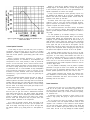
. . . . . . . . . . . 100 watts continuous (RMS); (to 8 ohm load, see Figure 3, Page 7)
Voltage Gain
. . . . . . . . . . . . . . . . . . . . . . . . . . . 60 db “Mic.” Input Level (8 ohm load)
49 db “Inst.” Input Level (8 ohm load)
Frequency Response . . . . . . . . . . . . . . . . . . . . . . . . . .
± 2 db 40 Hz. to 20,000 Hz. (typical)
Input Impedance . . . . . . . . . . . . . . . . . . . . . . . . . . . . . . . . . . . . .60,000 ohms “Mic.” Input Level
120,000 ohms “Inst.” Input Level
Distortion . . . . . . . . . . . . . . . . . . . . . . . . . . . . . . . .
5% maximum at rated output at 1 KHz.
Hum and Noise . . . . . . . . . . . . . . . . . . . . . . . . . . . . . . . . . . . . . . . . 60 db below rated output
Speaker Load Impedance . . . . . . . . . . . . . . . . Nominal 8 ohms; operational 5.3 ohms minimum
(See Figure 3, Page 7)
Input Clipping Level . . . . . . . . . . . . . . . . . . . . . . . Greater than 300 Mv. (“Mic.” Input Level)
Greater than 1 V. (“Inst.” Input Level)
Bass Control Action . . . . . . . . . . . . . . . . . . . . . ± 13 db at 100 Hz. with respect to “flat” setting
Treble Control Action . . . . . . . . . . . . . . . . . . ± 10 db at 10,000 Hz. with respect to “flat” setting
“To Tape Recorder” Jack . . . . .
Impedance 5,000 ohms; Output 19 db below speaker output;
nominal - 2 V at 50 watts to speakers, Clipping Level 4 V.
Echo-“To Input” Jack (Output To External Echo Unit) . . . . . . . . . . . .
Impedance 10,000 ohms;
Output 20 db above microphone inputs with individual volumes at “10”; Clipping level 3 V.
Echo-“To Output” Jack (Input From External Echo Unit) . . . . . . . . . . Impedance 40,000 ohms;
Sensitivity 200 Mv. for rated amplifier output with “Echo Gain” Control and
“Master Volume” Control at maximum settings; Clipping level 2 V. with maximum
setting of “Echo Gain” control. Clipping level increases with reduced setting
of “Echo Gain” control.
“Reverb Switch“ Jack . . . . . . . . . . . . . . . . D.C. switching (no audio), parallels the Master Reverb
In-Out Switch. Any cable with a resistance of less then 5,000 ohms may be used.
Center Notch Frequencies of “Anti-Feedback” Filters. . . . . . . . . . . . . .
5,000 Hz.
2,200 Hz.
1,000 Hz.
155 Hz.
2
VA300-C Console (cont’d)
Power Supply . . . . . . . . . . . . . . . . . . . . . . . . . . . . . . . . .
Power Consumption
. . . . . . . . . . . . . . . . . . . 80 watts maximum with no signal in.
180 watts with 1 KHz. signal and 100 watts output
400 watts maximum operating
Ambient Temperature Range
Dimensions
120 volts, 60 Hz.
. . . . . . . . . -7°C to 43°C (20°F to 110°F) without derating
. . . . . . . . . . . . . . . . . . . . . . . .
213 mm height x 635 mm width x 375 mm
depth (8-3/8 in. x 25 in. x 14-3/4 in.)
Weight . . . . . . . . . . . . . . . . . . . . . . . . . . . . . . . . . . . . . . . . . . .
17.25 kg (38 Ibs.)
VA300-S Speaker Column
Power Rating . . . . . . . . . . . . . . . . . . . . . . . . . . . . . . . . . . . . 100 watts
Impedance . . . . . . . . . . . . . . . . . . . . . . . . . . . . . . . . . . . . 16 ohms
Frequency Response
Horizontal
Vertical
50 Hz. to 10,000 Hz.
Distribution . . . . . . . . . . . . . . . . . . . . . . . . . . . . . . . .
Distribution
Dimensions
. . . . . . . . . . . . . . . . . . . . . . . .
140°
. . . . . . . . . . . . . . . . . . . . . . . . . . . . . . . . . . . 65°
. . . . . . . . . . . . . . . . . . . . . . . . . . .
1594 mm height x 400 mm width x 222 mm
depth (62-3/4 in. x 15-3/4 in. x 8-3/4 in.)
Weight . . . . . . . . . . . . . . . . . . . . . . . . . . . . . . . . . . . . . . . . . . . .
31.78 kg (70 Ibs.) including cable
DESCRIPTION
The Shure Model VA300 Vocal Master Sound System consists of one Control Console (VA300-C) and two Speaker
Columns (VA300-S).
Designed specifically for the performing vocalist, the
VA300 Vocal Master Sound System provides the required
portability, flexibility, and dependability demanded by professional entertainers.
The VA300-C mixer/power amplifier Console permits the
user to mix up to six microphones with individual control over
volume, tone and reverberation. A solid-state 100 watt R.M.S.
power amplifier is incorporated in the Console. Unique circuitry design protects the solid-state components against damage as a possible result of open-circuit or short-circuit conditions of the amplifier outputs. The output transistors are also
protected against overheating by the use of automatic thermal
sensors. All components of the VA300 Vocal Master Sound
System are conservatively rated and are operated well within
their respective tolerances to assure long life and trouble-free
performance.
The VA300-C is Underwriters Laboratories, Inc. listed, and is
listed by the CSA Testing laboratories as certified.
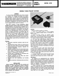
The VA300-S Speaker Columns are highly directional, wide
range, line-radiators. A rear-ported enclosure is utilized which
contributes to the directional characteristics of the Speaker
Column and is crucial in reduction of feedback.
The VA300-S employs four special 8-inch loudspeakers and
two special 10-inch loudspeakers providing a total cone area of
2,310 cm² (358 in²).
Each Speaker Column is furnished with a 15m (50 ft) #18
gauge, 2-conductor rubber jacketed cable with locking phone
plugs attached.
3
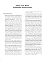
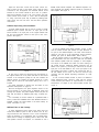
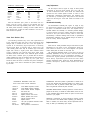
Figure 1
Front Panel Controls (Refer to Figure 1)
6. Individual Channel “Treble & Bass” Controls (Six, Dual
Concentric).
7. Individual Channel “Reverb” Switches (Six).
8. “Master Volume” Control.
1. “Anti-Feedback” Switches (Four).
2.
3.
4.
5.
“Reverb Intensity” Control.
“Reverb Treble & Bass” Controls (Dual Concentric).
“Master Reverb” Switch.
Individual Channel “Volume” Controls (Six).
9. “Thermal Overload” Indicator Lamp.
10. “On-Off-On” Power Switch.
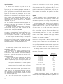
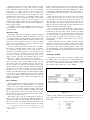
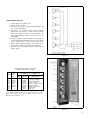
Figure 2
Rear Panel Controls and Connections (Refer to Figure 2)
4
11. Line Cord Storage Spindles.
17. “Reverb Switch” Remote Control Jack (Phone Type).
12. A. C. Line Cord.
18. Echo-“To Input” Jack (Switching Phone Type).
13. D. C. Fuse (3AG/5A).
19. Echo-“To Output” Jack (Switching Phone Type).
14. A. C. Fuse (3AG/3ASB).
20. Echo “Gain” Control.
15. “Speaker” Output Jacks (Two, Phone Type).
21. “Mic./lnst.” Input Attenuator Switches (Six).
16. “To Tape Recorder” Jack (Phone Type).
22. “Input” Jacks (Six, Phone Type).
VA300 Vocal Master
OPERATING INSTRUCTIONS
“On” position results in the least amount of hum
coming from the speakers.
General Operating Instructions:
1. Set all front panel controls in the following manner: All
switches (1), (4). (7). set to “Out” position; “Reverb
Intensity” Control (2). and all “Volume” Controls (5)
and (8), set at “0”; all “Treble” and “Bass” Controls
(3) and (6). set in the “flat response” position
(indicator ribs at 12:00 o’clock); “On-Off-On” Switch
(10) set in the “Off” position.
2. Unwrap the A.C. Line cord (12) from the storage
spindles (11); plug line cord into a 110 to 130 volt, 60
Hz. outlet. The line cord is a 2.75m (9 ft), 3-conductor
cord with a 3-pin grounding plug. If extension cords are
required, use a high quality, rubber-jacketed cable with
#18 gauge wire or larger.
3. Remove the speaker cables from the storage compartments in the VA300-S Speaker Columns. Insert and lock
the right angle phone plug on the cable into either of
the two parallel-wired phone jacks; one on each Speaker
Column. Connect the other end of each cable to the
jacks on the rear panel of the Console marked
“Speakers” (15). These plugs are provided with locking
rings to lock the plug to the jack. Each speaker cable is
15m (50 ft) in length and is made from heavy duty
2-conductor, #18 gauge unshielded cable. Since each
Speaker Column has a pair of parallel-wired input jacks,
an alternate speaker hook-up would be to connect a
speaker cable from the Console to one Speaker Column
and then connect a second cable from this Speaker
Column to the second Speaker Column. Either hook-up
will provide an 8 ohm load. If longer speaker cables are
required, see page 6.
4. Connect one or more high impedance microphones to
the Console at the connectors marked “Inputs” (22).
The VA300 is designed to operate with any high
q u a l i t y d y n a m i c o r ribbon-type high impedance
microphone. For low impedance microphones see page
10.
5. Set all six Input Attenuator Switches (21) on the rear
panel of the Console to “Mic.” These switches should
generally be set in the “Mic.” position when using high
impedance dynamic or ribbon microphones. See page
6 for a description of the switch function.
6. Turn on the Power Switch (10) located on the front
panel of the Console. Set the “Master Volume” Control
(8) to “5.” While talking or singing into one of the
microphones connected to the console, turn up the
individual volume control for that microphone to a
normal level. If at this point a slight hum is heard in the
speakers, switch the Power Switch (IO) to whichever
7. N o w t u r n u p t h e o t h e r I n d i v i d u a l C h a n n e l V o l u m e
Controls (5) which are being used. By use of the Individual Channel Volume Controls (5), the microphones
may be balanced for level so that the sound coming
from the speakers is in proper balance for each microphone. Increasing or decreasing the Volume on one
channel will have no effect on the other channels of the
Console.
8. Note the action of the Individual Treble and Bass Controls (6); these controls are of the dual concentric type,
the large knob being the Bass control and the smaller
knob being the Treble control. Each of these knobs
incorporates an indicating rib. Under average conditions, the controls should be set with indicating ribs
facing straight up (12:00 o’clock position) to provide a
normal “flat” frequency response. All Treble and Bass
Controls on the Console operate in the same manner;
turning the controls clockwise respectively increases
Bass or Treble, counterclockwise decreases Bass or
Treble. Note that changing the Bass or Treble Controls
on one channel has no effect on the other channels of
the unit.
9. Turn the Reverb Intensity control (2) to a setting of
“4” Set the Master Reverb switch (4) to the “In”
position. Reverberation may now be selectively added
to any of the six channels by setting the Individual
Channel Reverb switches (7) to the “In” position. Note
that different settings of the Reverb Intensity Control
(2) will not effect the overall system gain. Generally a
setting of “1” to “4” of the Reverb Intensity Control
(2) is adequate for vocals. The Reverb Treble and Bass
Controls (3) operate in the same manner as those of the
individual channel Treble and Bass Controls but provide
independent tonal balance of the reverberant signal
only. These controls do not affect the tone of the
individual channels. For example, increasing Treble and
decreasing Bass will approximate the reverb sound of a
tape-type reverberation unit while decreasing Treble
and increasing Bass will approximate the sound of a
plate-type reverberation device.
10. Set all four Antifeedback switches (1) to the “Out”
position. These switches can help eliminate feedback.
Each
switch
cuts
out
part
of
the
critical
feedback-generating frequencies. See page 8 for a
detailed description on how to effectively use them,
11. The Master Volume Control (8) will raise or lower the
volume of all channels simultaneously without affecting
the “balance,” or “mix.” NOTE: With the Console
driven at or near full power, pilot lamps will dim or vary
in brightness; this is a normal condition.
5
Input Connections:
Six individual input connectors are provided on the rear
panel of the Console. These connectors are standard 1/4 inch
phone jacks (22). The Console is designed to operate with any
high quality dynamic or ribbon-type high impedance microphone. High impedance microphone cables should be limited
to a maximum length of 6m (20 ft) to avoid high frequency’
signal loss and to reduce the possibility of hum and noise
pickup in the cables. Standard 1/4 inch phone plugs should be
attached to the “Console end” of the microphone cables; the
center conductor of the cable should be attached to the “tip”
terminal of the phone plug and the shield of the cable should
be connected to the “sleeve” terminal. For low impedance
microphones, see page 10.
For additional microphone inputs, see page 10. For connections from electrified musical instruments, see page 10. For
connections to play back a tape, see page 9. For connections
to a phonograph, see page 10.
Six individual input level adjustment switches (21) are located above the six input jacks. These screwdriver-slot slide
switches allow the microphone input signal to be attenuated
(reduced) before entering the preamplifier.
With the switch in the “Mic.” position, the signal from the
microphone is switched directly to the preamplifier of the
channel. With the switch in the “Inst.” position, the signal
from the microphone is attenuated by 11 db before entering
the preamplifier.
This feature may be useful when working the microphones
very close to the performer’s lips as with “hard rock” vocalists,
who may produce signals in excess of the clipping level of the
preamplifiers; in such an instance, the attenuator will generally
eliminate the distortion which would otherwise occur.
Output Connections:
Two parallel-wired “Speaker” output connectors are provided on the rear panel of the VA300. These connectors are
standard phone jacks (15).
Full rated output of the amplifier is obtained when the
speaker load is 8 ohms (two VA300-S Speakers). Speaker loads
of less than 5.3 ohms (more than three VA300-S Speakers)
should not be used with this amplifier. No damage to the
speakers or amplifier will occur, but thermal shutoff of the
amplifier may result.
It should be noted that various speaker loads will affect the
output power of the amplifier. See Figure 3, Page 7 to
determine amplifier output power for the given speaker load.
WARNING: Do not interconnect the speaker output jacks
or the speaker cables between two VA300 Amplifiers
or the VA300 and any other amplifier. This may result
in damage to one or both amplifiers, and is not covered
by the Guarantee.
The VA300 does not use speaker output matching transformers and thus avoids the distortion, power loss and added
weight inherent in such transformers. The speaker output voltage is 28.3 volts, to an 8-ohm load, for 100 watts. This allows
long speaker lines with wiring practices consistent with those
used for 25-volt speaker lines.
Up to 30m (100 ft) of #18 gauge two-conductor cable
(such as Belden #8452, 8478, 8460, or 8461) may be used to
6
connect from the VA300-C to each 16-ohm (VA300-S)
speaker. Greater cable lengths require heavier gauge wire to
avoid appreciable power loss in the speaker cable. For 30 to
51m (100 to 170 ft), use #16 gauge; 51 to 81m (170 to 270
ft), use #14 gauge; and 81 to 128m (270 to 425 ft), use #12
gauge wire. To maximize the power to each speaker, a separate
cable should be used to connect each speaker to the VA300.
Speakers:
Selection of speakers for use in a vocal music system is most
critical. The factors which most significantly contribute to an
outstanding vocal speaker system are correct frequency range,
distortion-free reproduction, and enough sound power to fully
penetrate the audience area.
The Shure VA300-S Speaker Column has been designed to
provide all of these features. It is recommended that VA300-S
Speaker Columns be used in pairs, each column having a
nominal impedance of 16 ohms, which provides an impedance
of 8 ohms when two are used. Each column utilizes two
special IO-inch speakers and four special 8-inch speakers, and
has a total speaker cone area of 2,310cm² (358 in²) per
column. The VA300-S Speaker Column delivers virtually
uniform penetrating power over a 140° angle in the horizontal
plane and a 65° angle in the vertical plane. The rear-ported
enclosure of the VA300-S contributes to its highly directional
pattern, which is critical in achieving maximum audience
penetration and reduction of feedback.
The Shure VA301-S Speaker Column is intended primarily
for use as an “on-stage monitor.” While this speaker meets all
of the criteria for an excellent vocal system speaker, its area of
coverage is more localized than that of the VA300-S. The
nominal impedance of the VA301-S is 32 ohms, so that when
used in conjunction with two VA300-S Speaker Columns, the
total system impedance becomes 6.4 ohms. An integral volume
control on the VA301-S permits its use on-stage as a monitor
at the highest possible sound level without feedback.
The following list shows various speaker combinations and
the resultant impedance loads which are suitable for use with
the VA300 Vocal Master:
QUANTITY and SPEAKER MODEL
1 VA300-S
2 VA300-S
3 VA300-S
1 VA301-S
2 VA301-S
3 VA301-S
4 VA301-S
5 VA301-S
6 VA301-S
1 VA300-S and 1 VA301-S
1 VA300-S and 2 VA301-S
1 VA300-S and 3 VA301-S
1 VA300-S and 4 VA301-S
2 VA300-S and 1 VA301-S
2 VA300-S and 2 VA301-S
IMPEDANCE
OHMS (NOMINAL)
16
8
5.3
32
16
10.6
8
6.4
5.3
10.6
8
6.4
5.3
6.4
5.3
If additional speakers (more than in the table above) are
required, use a Shure PM300 Power Master Amplifier to drive
the extra speakers. See page 11 for instructions.
Keeping in mind that the speaker columns have a narrow
coverage angle in the vertical plane and a broad coverage angle
in the horizontal plane, here are a few generalizations on
speaker requirements for various room shapes.
A deep, narrow auditorium would generally require only
two speakers if the seating is all on one level. If balconies were
added to this same room, additional speaker columns would be
required to aim sound up into them.
A shallow, broad room might require four speakers to be
utilized in order to cover the extreme horizontal expanse.
Again if balconies were added, four more speakers might be
required to expand the vertical coverage.
The “Theatre-in-the-Round” will almost always necessitate
the use of at least four columns. More speakers might be required to provide adequate horizontal coverage if the theatre is
very deep.
Figure 3. Typical output power vs. speaker load impedance for the
VA300 Vocal Master
Column Speaker Placement:
It must always be kept in mind that every room or space is
acoustically unique and there are no set “rules” for speaker
placement. A number of generalizations however may be made
which will at least provide a good starting point under various
conditions.
Always consider speaker placement in relation to
microphone placement. It is desirable for the loudspeakers and
microphones to be in close proximity in order to provide the
illusion of source-oriented sound. Source-oriented sound,
ideally should provide the listener with the illusion that all of
the sound is coming directly from the sound source, the stage
or performance area. It is also desirable to keep loudspeakers
and microphones separated in order to achieve a high
threshold of acoustic feedback. While these statements are
contradictory, a good solution to both can generally be
accomplished.
When the VA300-S Speaker Columns are used on stage, as
they most often are with a portable system, the speakers
should be placed at the sides of the stage and as far forward as
possible. With this setup, the entire stage area will be relatively
free from acoustic feedback; also the illusion of sound coming
from the center of the stage will be quite good except for the
first few forward rows of seats.
The Shure VA300-S Speaker Column has been designed
with rear ports to give the column a bidirectional horizontal
polar pattern below 200 Hz. This design feature was decided
upon in order to reduce low frequency acoustic feedback and
provide a relatively “dead” area at the sides of the column
with the result that microphones may be placed there with
minimal feedback problems at low frequencies.
Try to keep the speaker columns above the heads of the
audience. The easiest way to do this is put the speaker columns on the stage. If the stage is only a foot or two high, raise
the speaker columns up by placing them on a solid platform or
box.
To “aim” speakers up for effective coverage of a balcony,
use the Shure Model A3S-S Speaker Stand. This stand will
provide added stability and approximately 150 of tilt. In an
emergency, a spare microphone stand can be used to hold up a
tilted speaker column. Adjust the height of the microphone
stand to one or two inches less than the height of the top edge
of the upper rear port on the back of the speaker. Tilt the
speaker back until the top edge of the upper rear port rests on
the top of the microphone stand. Changing the height of the
microphone stand adjusts the amount of tilt on the speaker.
The VA300-S Speaker Column may be used on its side,
though this reduces the horizontal coverage and the penetrating power. In a low ceiling, small intimate room such as a
night club, horizontal mounting, at or near the ceiling level
may be very successful. An alternate solution for this type of
small room is to use VA301-S Monitor Speakers. It is not
recommended that the VA300-S Speaker Column be used on
its side in larger rooms.
It is not possible to adequately cover all phases of speaker
placement in all types of rooms in this manual. Just remember
that every room is acoustically different from any other and
therefore speaker placement will vary from room to room.
Good speaker placement will provide the audience with
even distribution of sound intensity, sound which is free from
excessive reverberation and ethos, and the illusion of sound
emanating from the real source.
Power Connections:
Connect the line cord (12) to an outlet which supplies 120
volts AC, 60 Hz. power. The three-position toggle switch on
the front panel of the VA300 controls power to the Console.
This three-position switch (10) is used to reverse line polarity,
for minimum hum.
If extension cords are required to supply power to the
VA300, a high quality #18 gauge or larger cord should be
used.
Do not connect more than one VA300, or other amplifier
to one extension cord. Use separate extension cords for each
amplifier. Use a maximum of two VA300’s or other amplifier
per 120 volt house circuit. Failure to adhere to the above will
result in loss of available output power and the risk of blowing
house fuses, but will in no way damage the VA300 amplifier.
7
Thermal Overload/Ventilation:
The VA300 is equipped with thermal sensing switches on
the heat-sinks of the output transistors. The thermal switches
are set to shut off AC power to the amplifier when a
temperature of 90°C (194°F) is attained on the heat-sinks; the
switches will automatically recycle and return AC power when
the heat-sink temperature reduces to 73°C (164°F). A thermal
overload light (9), located on the front panel of the VA300,
will indicate if thermal cycling has occurred. Thermal cycling
may occur if air is not allowed to circulate through the grilles
of the amplifier, if there is a prolonged short-circuit on the
speaker output, or if the ambient temperature exceeds 43°C
(110°F) while the console is operating at or near full power.
Thermal cycling may also occur if the speaker load impedance
is less than 5.3 ohms. See page 6, Output Connections, for
instructions on speaker connections.
Anti-Feedback Switches:
Acoustic feedback (a howl or squeal in the speakers) may
occur, depending on room acoustics and the physical placement of microphones in relation to the speakers, when volume
is increased or when Bass or Treble controls are boosted. To
minimize feedback, four Anti-Feedback switches (1) are
incorporated in the VA300-C Console. These switches operate
four “notch filters” which modify the frequency response of
the unit. Each switch controls part of the audio spectrum. The
top switch (A-yellow colored) filters the highest feedback
pitch (squeal), while the bottom switch (D-deep orange
colored) filters the lowest feedback pitch (howl). The middle
switches (B and C) filter the middle feedback pitches. The
action of each filter, with the exception of the (D) filter, has
very little effect on the tonal quality of the voice. When using
the (D) filter, a decrease in bass tones may be noticed. To
compensate for this, simply increase all the Individual Channel
Bass controls slightly for the desired sound. This feedback
switch (D) may be used in a very “boomy” environment to
eliminate some of the low frequency room reverberation.
If feedback occurs, locate the one Anti-Feedback switch (1)
which eliminates the feedback. Gain may then be increased or
tone control increased until another feedback pitch is apparent. One of the other filters may then be introduced which
will eliminate that feedback. IMPORTANT: no more than two
filters should be used simultaneously; the effect of more than
two filters is one of reducing overall gain and the overall tonal
quality of the system may be significantly affected.
Mixing:
Each of the six channels employ an individual Volume
control, Bass control, Treble control, and reverberation
selector switch.
Individual Volume controls permit proper mixing of the
various inputs.
The Bass control allows 13 db of boost or attenuation at
100 Hz. It permits enhancement of a thin voice and is often
useful as a low frequency attenuator in “boomy” rooms.
8
The Treble control permits 10 db of boost or attenuation at
10 kHz., and is useful to “brighten” an otherwise flat-sounding
voice. It is often used to great advantage to reduce high
frequency acoustic reverberation in reflective rooms.
The Master Volume control (8) adjusts the output level of
the total mixed output, allowing simultaneous increase or
decrease of all channels without affecting the mix of the
inputs.
Reverb:
The VA300 Console includes a built-in electromechanical
spring-type reverberation device utilizing a total of four coil
springs in two transmission paths. Reverberation is
accomplished by driving the input ends of the springs in a
torsional mode and transferring the torsional movement at the
other end of the springs back into an electrical signal which
exhibits time delay and long decay time. Since the
reverberation device is an electromechanical device, it is
sensitive to mechanical shock. It is recommended that if the
console is moved while operating, the Master Reverb In-Out
switch (4) be set to the “Out” position. This will avoid the
possibility of jarring the springs and producing unwanted
sounds.
Unique to the Vocal Master is the fact that no matter how
much reverberation is used, there is always a backbone of
“dry” signal on the total output. Of great importance to the
user, and also unique to the Vocal Master, is the system which
permits the reverb intensity to be increased without increasing
overall gain. In most units which employ artificial reverberation, as the intensity of the reverberant signal is increased, the
total gain also increases; this usually leads to acoustic feedback. The reverb mixing system used in the Vocal Master reduces the “dry” signal as the reverberant signal is increased;
this accounts for an almost constant gain and reduces the possibility of feedback as reverb is added.
Three controls are pertinent to the VA300-C reverb
operation. The amount of reverb is selected by the Reverb
Intensity control (2). Generally, this control is not used above
a setting of “5” for vocalists, though higher settings may be
required for instruments. Separate Reverb Bass and Treble
controls (3) are provided for the reverb signal only and are
independent of the other tone controls on the unit. These
controls modify the reverberant signals in essentially the same
way the individual channel tone controls modify the
non-reverb, or “dry” tones. The reverb tone controls allow the
user to change the reverberant sound to compensate for the
reverberation of each room in which the system is used. In a
“boomy” sounding room, decrease the Reverb Bass control or
increase the Reverb Treble control, or do both to equalize the
reverb signals for the desired sound.
The individual channel Reverb In-Out switches (7) are basically intended to allow the user the option of having reverb on
one or more channels while retaining a “dry” (non-reverb)
signal on the other channels. These switches can also be used
to perform a variety of other functions which are described
under Special Operating Instructions.
The master Reverb In-Out switch allows instantaneous reverb turn-on or shut-off, no matter how the individual channel
reverb selector switches are set. This feature allows the user to
“pre-program” the console for reverberation.
A phone jack marked “Reverb Switch” (17) is located on
the rear panel of the console. This jack parallels the Master
Reverb In-Out switch (4) and allows the reverb to be
remotely turned on and off when the Master Reverb switch is
in the “In” position. The Master Reverb switch will always
override the remote switch and turn off the reverb, so care
should be taken to insure that the Master Reverb switch is in
the “In” position if an external remote switch is desired to
control the reverb switching.
Since the remote switching is D.C., and no audio appears on
this jack, any length of unshielded cable can be used between
the Console and the remote switch without hum or noise. The
remote switch can be any single pole, single throw switch.
To Tape Recorder:
A phone jack on the rear panel marked “To Tape Recorder”
is provided for connections to tape recorders for making
recordings, or to additional power amplifiers, such as the
PM300. For specific instructions for such connections see the
section marked Special Operating Instructions.
The signal at this jack is the same signal that drives the
Console power amplifier and is considered to be an auxiliary,
high impedance output for driving high-level, high impedance
inputs. Note that all the Console controls, Master Volume,
Antifeedback, Reverb, etc., affect this signal.
VA300 Vocal Master
SPECIAL OPERATING INSTRUCTIONS
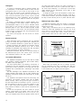
Echo:
Echo may be introduced into the VA300-C by using an
accessory echo device (such as an Echolette or Dynacord).
To use an external echo device in conjunction with the
VA300, interconnect the two units as follows: attach low
capacitance, single conductor, shielded cable to the Console
jack marked Echo “To Input.” Connect the opposite end of
this cable to the echo device jack marked “Input” (Aux. High
Level). Connect a similar cable to the echo device jack marked
“Output” (Aux. High Level) and connect the opposite end of
this cable to the Console jack marked Echo “To Output.”
Using the “Echo Gain” Control in
level controls on the echo unit, the
balanced with the gain of the VA300 so
level when the individual Reverb In-Out
conjunction with the
echo signal may be
there is no change in
switches are operated.
When connected in the manner described, the individual
channel Reverb In-Out switches will offer selective echo in
addition to selective internal reverb. With the Master Reverb
In-Out switch in the “Out” position, the individual channel
Reverb switches will select “dry” (no echo) in the “In” position and “Echo” in the “Out” position.
Changing the Master Reverb In-Out switch to the “In” position will permit selection of echo (individual channel Reverb
switch “Out”) or reverb (individual channel Reverb switch
“In”).
The output signal of the VA300-C at the jack marked Echo
“ T o O u t p u t ” is considered high level and is suitable for use
with loads of 10 kilohms or greater. The jack marked Echo
“To Input” presents a 40 Kohm load to the source and will
accept high level signals. Some echo units employ inputs
suitable only for very low level; in such cases, a resistance pad
(attenuator) will be required in the line from the VA300-C to
the echo device input. If the echo device input is suitable for
only high impedance microphones a resistive pad consisting of
a 100 kilohm and a 3.3 kilohm resistor is required. (See figure
4). Almost all makes of echo units use different output levels;
these may generally be compensated for by use of the gain
Figure 4
controls on the echo unit and the “Echo Gain” control on the
Console.
Tape Recording:
To tape record the VA300 output, connect a low
capacitance, single conductor, shielded cable (such as Belden
#8401, #8410, #8411) from the jack marked “To Tape
Recorder” to the Auxiliary High Level Input of the tape recorder.
Limit the cable length to 15m (50 ft) to avoid loss of high
frequency signal and to reduce the possibility of hum pickup.
Use the tape recorder controls to set recording levels. Note
that the VA300 Master Volume control affects the signal level
at the “To Tape Recorder” jack. To make stereo tape
recordings see the section on stereo operation, on page 12.
Playing Tapes:
To play back tape recorded material through the VA300,
connect a cable from the tape recorder’s High Level Output to
one of the six Input jacks on the Console. Set that channel’s
Input Attenuator Switch to “Inst.” Individual channel Treble
and Bass controls should be set to 12:00 o’clock.
The individual channel Volume Control may be used, in
conjunction with the tape recorder playback level control, to
adjust volume.
9
Phonographs:
To connect a” phonograph having a magnetic cartridge, and
no preamplifier, to the VA300, attach a cable from the
phonograph output to one of the six Input jacks on the
Console. Set that channel’s Input Attenuator Switch to the
“Mic.“ position. Set the Treble control for that channel at
9:00 o’clock and the Bass control at 3:00 o’clock to provide
approximate R.I.A.A. phono equalization. Use the individual
channel Volume Control to adjust the volume from the phonograph.
To connect a phonograph having a magnetic cartridge, and a
phono preamplifier, to the VA300, connect a cable from the
phono-preamplifier output to one of the six individual channel
input jacks on the Console. Set that channel’s Input
Attenuator Switch to “Inst.” Set the Treble and Bass controls
for that channel to 12:00 o’clock. Use the individual channel
Volume Control in conjunction with the phonograph’s level
control, to adjust the volume.
For stereo phonographs see the section on Stereo
Operation.
the same when talking directly into either microphone or
directly between them if they are in phase with each other. If
the sound drops drastically, or a dead spot is found when
talking between the two microphones, one of them, or their
cables, is out of phase.
To change the phase of the one microphone, or cable, interchange the conductors that are wired to Pins No. 2 and No. 3
of the Cannon connector. Test all the microphones and cables
this way to insure that they are all “in phase” with each other.
Additional Inputs Using a Mixer:
If additional microphone inputs are required, a microphone
mixer (such as a Shure M68 type) or a second Vocal Master
Console may be used.
When using a microphone mixer for the additional inputs,
connect the mixer High Impedance Mic. Output to one of the
Input jacks on the VA300 Console. The individual input
control on the channel, bass, treble, volume, and reverb,
provide master control over the mixer inputs. See Figure 5.
Musical Instruments:
Most electrified musical instruments may be amplified
through the VA300 with great effectiveness. Generally the
output of electrified instruments is greater than the output of
a dynamic microphone and therefore the individual channel
Input Attenuator Switches should be set to “Inst.” to avoid
exceeding the preamplifier input clipping level. See the section
on Input Connections for further information.
Electrified instruments may then be connected directly to
the individual Input jack. If low volume occurs, return the
Input Attenuator Switch to the “Mic.” position.
Low Impedance Microphones:
Low impedance microphones may be used with the VA300
when accessory matching transformers (Shure Model A95UF)
are added to the Input jacks (22).
The Shure Model A95UF Line Matching Transformer is
terminated at the high impedance end with a locking-type
phone plug for direct connection to the input jack; the low
impedance end is terminated with a Cannon-type, 3-pin female
connector.
The main advantage of low impedance microphones is that
virtually unlimited cable lengths may be used, whereas high
impedance microphones require that cable length not exceed
6m (20 ft).
Low impedance microphones should be wired using low
capacitance, two-conductor, shielded cable (such as Belden
#8413, #8422). When wiring Cannon-type connectors,
the cable shield should be connected to Pin No. 1 and one of
the two conductors to Pin No. 2, the other conductor to Pin
No. 3. When using several microphones, consistency of cable
wiring should be followed to insure that all microphones are
“in phase.“
To test two microphones and their cables for proper
phasing, connect them to the VA300. Talk or sing into the
two microphones while holding them 8 to 10 cm (3 to 4 in.)
apart. The amplified sound from the Speaker Column will be
Figure 5
When reverb and external echo are not required, the mixer
may be connected to the Echo “To Output” jack. With this
arrangement the mixer Aux. High Level Output is connected
to the Console Echo “To Output” jack. See Figure 6.
Figure 6
10
Adjust the Echo Gain control and the mixer volume controls to match the gain of the VA300 inputs. With the mixer
connected in this configuration the individual Reverb In-Out
switches on the Console should be set to the “In” position.
When these switches are set to the “Out” position, that individual channel will be muted, or “cued.” See the description
on “cuing.” Still more inputs may be added by stacking additional mixers onto the first mixer. See the Mixer Operation
Instructions.
PM300 Power Master amplifier and additional Speaker Columns. Generally two Speaker Columns should be connected to
each amplifier. See Figure 8.
Additional Inputs Using a Second VA300-C:
A second VA300 Console may be used as a mixer to provide
additional inputs. Connect the Echo “To Input” jack on the
second Console to an Input jack on the original Console and
set the Input Attenuator switch on that input to the “Inst.”
position. See Figure 7.
Figure 8
Figure 7
At this point it should be noted that the microphones on
the original Console are out of phase with those on the second
Console. If the microphone pickups for the two Consoles are
different sources, for instance the original Console is a vocal
pickup and the second an instrumental pickup, this is not a
problem.
For further information on Phasing see the section on Low
Impedance Microphones on page 10.
With this arrangement, the power amplifier section on the
second Console is not being used. If additional power and
coverage are required, this power amplifier section may also be
used. See the section on additional power using a second Console.
If it is necessary to use two consoles on a permanent basis a
factory authorized COMMON MIX. BUS MODIFICATION is
available. Contact your Shure Dealer or the Shure Factory for
further information on this.
To use the PM300 Power Master Amplifier, connect a cable
from the VA300 Console jack marked “To Tape Recorder” to
an input on the PM300 Amplifier. The cable used should be
limited to 15m (50 ft) of low capacitance, single conductor,
shielded type (such as Belden #8401, #8410, #8411).
Set the Volume Control on the PM300 to “7” to obtain the
same amplification level from both the VA300 and the PM300
when identical speaker loads are employed on each amplifier.
The output of the PM300 will “follow” all control settings of
the VA300 Console. Additional PM300 Amplifiers may be
added to the system by connecting a cable from the unused
input jack on the last PM300 to one of the input jacks on the
next PM300. See Figure 8. NOTE: The unused input jack on
the last PM300 in the “chain” can then be used for tape
recording. See the Special Operating Instructions on Tape
Recording.
To use a second VA300 Console in place of a PM300 to
obtain additional power, connect a cable from the original
VA300 Console jack marked “To Tape Recorder” to the jack
marked Echo “To Output” on the second VA300 Console. See
Figure 9.
Additional Power or Area Coverage:
In those applications which require more power than one
VA300 Vocal Master system is able to deliver, such as very
large auditoriums and stadiums, and in those installations
where the audience is so widespread, such as Theatre-in-theRound and for coverage in adjoining rooms or when more than
three speaker columns are required, it is advisable to use a
Figure 9
11
Set the controls on the second VA300 Console as follows:
Antifeedback Switches to “Out,” Master Reverb Switch
“Out,” Individual Volume Controls to “0,” and the Master
Volume to “5.” Adjust the Echo “Gain” Control to
approximately 1/3 rotation from the c.c.w. off position, and
use this control as a volume control to obtain the same
amplification level from both of the VA300 Consoles. Once
the Echo “Gain” Control is preset, the output of the second
VA300 Console will “follow” all control settings of the
original VA300 Console. Small changes in amplification level
on the second VA300 Console can be made by adjusting its
Master Volume Control.
An additional VA300 Console, PM300 or tape recorder can
be connected to the “To Tape Recorder” jack on the second
VA300 Console.
Microphone Cuing:
Microphone “cuing” may be preset by using the individual
Reverb “In-Out” switches to reduce the volume of, or turn off
an unused individual microphone channel. This is useful when
it is desired to preset the individual volume controls but only
have one or two microphones “live” at a time. This allows
tighter control of feedback, or additional control to avoid
pickup from off-stage microphones.
Insert an unwired phone plug into the Echo “To Output”
Jack. With the individual Reverb switch in the “In” position,
the channel will operate normally. In the “Out” position, the
channel level is reduced or turned off. The level of the “Out”
or “Cued” channel is controlled by the “Echo Gain” control;
turning this control fully counterclockwise turns off the
“Cued” channel. Returning the individual Reverb “In-Out”
switches to “In” restores the channel to the normal level.
For remote “Cuing” on and off, plug a foot switch into the
Echo “To Output” Jack on the VA300 Console. Turn the
“Echo Gain” control fully clockwise. With the foot switch in
the “On” position, the channels will operate normally. With
the foot switch “Off” those channels switched to individual
Reverb “Out” are turned completely off. This is useful for
remotely turning on and off preselected channels (Microphones). The cable used with the foot switch should be limited
to 15m (50 ft) of low capacitance, single conductor, shielded
type (such as Belden #8401, #8410, #8411) to avoid high
frequency signal loss and to reduce the possibility of hum
pickup in the cables.
Console speakers will require that the individual channel
Reverb “ln-Out” switches be in the “In” position. The channels
on which the switches are in the “Out” position will be heard
at the speakers connected to the PM300. This may be used for
a special echo effect, like “throwing” a voice from the rear of
the room.
Stereo recordings may also be made using one VA300
Console and one PM300. One channel of the stereo tape
recorder would be fed from the Console jack marked “To
Tape Recorder;” the other channel would be fed from the
open input jack of the PM300. NOTE: Reverberation can be
added to only those channels that are being reproduced by the
speakers connected to the VA300 Console.
A very convenient way of recording with a stereo tape recorder is to record the vocals on one tape channel and the
instruments on the other tape channel. Connect the VA300
“To Tape Recorder” jack to the right channel auxiliary input
of the tape recorder. A separate microphone is connected to
the left channel microphone input of the tape recorder; an
omnidirectional microphone suspended from the ceiling is
recommended.
A stereo phonograph may be connected for stereo operation
with either of the two above systems. Connect the left phono
output to one Input, and the right phono output to a second
Input. Refer to the section on Phonographs on page 10, for
Input arrangements. Set the individual Reverb In-Out switches
on these two channels to direct the sound to the left and right
speakers.
Connecting a VU Meter:
An external VU meter may be connected in parallel across
the speaker wires of the VA300 with a resistor attenuator, as
shown below. Use a true VU meter (such as Simpson Model
No. 1349) and three resistors connected as shown. The resistors should be ½-watt carbon 5%, or 1% if available.
Stereo Operation:*
Stereo operation may obviously be obtained by using two
VA300 systems without any interconnections. If it is desired
to have one of the microphones connected to both systems,
simply use a “Y” connector on that microphone and feed its
signal to one Input on each Console. For making stereo tapes,
the “To Tape Recorder” jacks, one on each console, may now
be connected to the left and right Auxiliary Inputs, respectively, on a stereo tape recorder.
Alternatively, stereo may be accomplished by using one
VA300 system and one PM300 with additional speakers. A
connection is made from the VA300 jack marked Echo “To
Input” to an input of the PM300. Those input channels of the
Console which are to be reproduced through the VA300
* As a general rule stereo sound reinforcement of this type
is quite annoying to listen to and is recommended only for
special effects.
12
Figure 10
With an 8-ohm speaker load (two VA300-S) zero VU is 50
watts. Output power for other VU readings is shown in the
table below.
VU
+3
0
- 3
- 7
-10
Power to 8-ohm load
100 watts
50 watts
25 watts
10 watts
5 watts
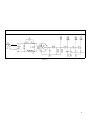
VA300-C FUNCTIONAL DIAGRAM
Figure 11
VA300 Vocal Master
SERVICE INSTRUCTIONS
Amplifier Service (See Guarantee):
The VA300 Vocal Master Console uses components of the
highest quality, operating well within their respective ratings
to assure long life. CAUTION: There are no user serviceable
parts inside. Refer servicing to qualified service personnel.
Amplifier Removal:
To remove the amplifier from its carrying case, remove the
three screws located at the top front edge of the case and the six
screws, four within the plastic feet, on the bottom of the case.
Push the amplifier slightly forward from the back to permit
access to the front panel. (Note: Uncoil the cable before
pushing the chassis. Push against amplifier chassis not against
the grille on the back.) The entire amplifier may be pulled
forward at this point and separated from the case.
Front Panel Removal:
To ease servicing of components on the front panel, remove
the four screws on the bottom rim of the front panel. (Note:
Stand amplifier on end with transformer side down). Figure
12, Page 14, shows the amplifier with the front panel
removed and tilted to a convenient servicing position.
13
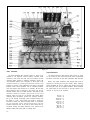
Figure 12
Driver Transistors:
Output Transistors:
The driver transistors Q33 and Q34, Figure 12, Page 14 are
located on the amplifier chassis. Before removing these
transistors, write down the lead color and location at each
transistor solder junction. If replacing transistors, apply type
120 Wakefield thermal joint compound to each side of the
insulation wafer to provide good thermal transfer from
transistor to chassis. After replacement and before connecting
transistor leads, check transistors with an ohmmeter between
case and chassis; there should be no continuity. Be sure that
these transistors are not inverted in the circuit; they are not
identical devices. Q33 is an NPN transistor, while Q34 is PNP
transistor. Refer to the lower right corner of the circuit
diagram, Figure 18, Page 21, for terminal code. NOTE: When
replacing driver transistors, perform the following modification (if not already performed): place insulated tubing over
the leads of a 3.3k, 1/2W resistor and solder it across the
terminals to which the white and black leads of transformer
T2 are connected. Add a second ground wire from the
terminal nearest the front of the unit to which resistor R21 is
connected, through the chassis grommet, to the ground on the
Speaker Output jacks (same path as existing wire).
The output transistors Q35 through Q38, Figure 12, Page
14 are located on the black finned heat sinks. Replacement
procedure is the same for the driver transistors, Q33 and Q34.
14
NOTE: The output transistors, Q35 through Q38, must be
matched for current gain and part number. When replacing
output transistors be sure to replace with devices which have
the same gain code as the original transistors. Shure transistors
are coded either by the last letter in the part number or a
color-dot on the top of the transistor.
Blue Dot = A
Red Dot = B
Orange Dot = C
Yellow Dot = D
Green Dot = E
Brown Dot = F
Pink Dot = G
Violet Dot = H
Black Dot = J
White Dot = K
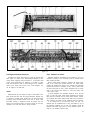
Figure 13
Figure 14
Small Signal and Predriver Transistors:
Check Transistors and Diodes:
Transistors Q1 through Q30, Figure 14, Page 15 and Q31 and
Q32, Figure 12, Page 14 are mechanically supported by their
leads. When replacing these transistors, it is imperative that
proper lead configuration be followed. A minimum of soldering heat should be used to avoid damage to the transistor.
Refer to the lower right corner of the circuit diagram, Figure 18, Page 21, for lead code.
Defective transistors and diodes may be located by use of an
ohmmeter. Polarity of the ohmmeter must be verified before
these checks are made.
With a known diode orientation, measure the diode resistance in the forward and reverse directions. The lowest meter
reading will establish the probe at the cathode end (schematic
symbol arrow points to cathode) as the “minus” probe while
the other probe will be “plus”. Some ohmmeters are not polarized in this manner with relation to “volts plus probe” and
“volts minus probe.”
To check transistors, the ohmmeter should be set to the 100
ohm or 1,000 ohm scale. Small signal transistors (Q1 through
Q32) must be removed from the circuit before testing. Transistors mounted with screws (Q33 through 038) may be tested in
place; however, the leads to these transistors must be removed.
If all conditions in the following table are met, the
transistor may be considered free of any gross defect; if any of
the following conditions are not met, the transistor should be
replaced. See lower right corner of circuit diagram, Figure 18,
Page 21, for transistor terminal code.
Diodes:
Diodes D6 and D7, see Figure 12, Page 14 are located on the
black finned heat sink with the output transistors. Special care
is required to insulate these diodes from the heat sink while
providing good thermal transfer from sink to diode. Heat
shrinkable tubing or “spaghetti” should be placed over the
diode and connecting leads; the diode should be securely
clamped to the heat sink with the clamp provided.
15
OHMMETER CONNECTIONS
“Plus” Lead
“Minus” Lead
Collector
Emitter
Collector
Emitter
Base
Base
Emitter
Collector
Base
Base
Collector
Emitter
OHMMETER READING
N.P.N. Transistor P.N.P. Transistor
High
High
High
High
Low
Low
High
High
Low
Low
High
High
With the ohmmeter “plus” probe on the anode end of a
d i o d e , a n d t h e “ m i n u s ” probe on the cathode end, the
ohmmeter should read approximately 2000 ohms or less. With
the meter probes reversed, a reading of about 10,000 ohms or
more should occur. If either of these conditions is not met, the
diode should be replaced.
Power Drain Resistor (RSEL):
The following condition may occur after replacement of
driver transistors Q33 and Q34, output transistors Q35
through Q38, or diodes D6 and D7. If the unit appears to
operate at an excessively high temperature or thermally
recycles after about 10 minutes with no signal input, the
“cold” standby power drain may be excessive (up to 20 watts
higher than normal; a higher power drain indicates further
circuitry problems). The nominal power drain under these
conditions should be 60 watts; if the measured figure exceeds
75 watts, insert a resistor (R SEL ) in parallel with the 56-ohm
resistor between the base of transistor Q33 and the junction of
diodes D6 and D8 (figure 17, page 21). R S E L (½W, 10%)
should be either 180 ohms to decrease the power consumption
by 20 watts, or 82 ohms to decrease the power consumption
by 30 watts.
EQUIPMENT DESIGNED FOR USE
WITH THE VA300 VOCAL MASTER
VA300-S
VA301-S
PM300
A3PC
A3PC-C
A3PC-S
A31PC-S
A3S-C
ASS-S
A50XC
A3S-T
A95 Series
16
Vocal Master Speaker Column
Vocal Master Monitor Speaker
Power Master Booster Amplifier
Soft Cover Set
Console Soft Cover
Speaker Column Soft Cover
Monitor Speaker Soft Cover
Fold-Up Console Stand
Speaker Stand
15m (50 ft) Speaker Extension Cable
Speaker Stand
Low Impedance Transformers
Lamp Replacement:
The two lamps I2 and I3, Figure 12, Page 14 which provide
illumination of the front panel controls are 115 to 125 volt,
15 watt incandescent bulbs. These bulbs are soldered and
epoxied into the molded plastic sockets in order to meet
Underwriters’ Laboratories requirements. The assembly may
be removed by unsoldering the lamp leads at the terminal
strips and removing the screw that holds the socket to the
chassis.
Reverberation Assembly:
The Reverberation Assembly M3, Figure 13, Page 15 may
be removed and returned to the factory Service Department
for repair if a malfunction should occur. The amplifier can be
operated without this assembly. To eliminate possible damage,
or shock hazard, the plug-in cables should be temporarily
inserted in the nylon inserts normally used to mount this
sub-assembly. If extensive damage has occurred, a replacement
Reverberation Assembly may be ordered through the dealer or
from the factory Service Department.
Replacement Parts:
Parts that are readily available through local electronic parts
distributors are not shown on the accompanying Parts List.
Their values are shown on the circuit diagram. The special
custom made parts are shown on the Parts List.
The commercial alternates shown on the Parts List are not
necessarily equivalents, but may be used in the even that direct
factory replacements are not immediately available. To
maintain the highest possible performance and reliability,
Shure factory replacement parts should be used. When
ordering replacement parts, specify the Shure Replacement Kit
Number, description, product model number and serial
number.
GUARANTEE: This Shure product is guaranteed in normal use to
be free from electrical and mechanical defects for a period of one
year from the date of purchase. Please retain proof of purchase
date. This guarantee includes all parts and labor.
SHIPPING INSTRUCTIONS: Carefully repack the unit and return it
prepaid to the factory. If outside the United States, return the unit
to your authorized Shure Service Center for repair. The unit will be
returned to you prepaid.
SERVICE: If information or service should be required, contact
your local Shure Vocal Master dealer explaining your difficulty in
detail. In addition, the Shure factory service department will be
ready to assist you immediately upon request.
VA300-S Speaker Servicing:
1. Unplug cables from speaker jacks.
2. Remove back of cabinet.
3. Disconnect one end of the lead connected between the
two 10 inch loudspeakers.
4. Apply 60 Hz, 1 to 10 volts, to each of the six speakers
individually. Any buzzes or rattles indicate possible
failure. The speakers should all sound generally alike
with a slight difference between the 8 inch and 10 inch
loudspeakers.
5. Using an ohmmeter, measure resistance of the voice-coil
of each loudspeaker individually. Each 10 inch speaker
should measure between 12 and 16 ohms. Each 8 inch
speaker should measure between 5 and 8 ohms. Readings outside of these limits indicate possible failure.
6. Reconnect lead disconnected in Step 3. Install back of
cabinet tightly.
Figure 15
REPLACEMENT PARTS LIST FOR
VA300-S SPEAKER COLUMN
ITEM
M10
M11
M12
M13
M14
M15
M16
M17
M18
REP.
KIT
NO.
RKC29
RKC56
RKC31
RKC25
RKC4
RKC32
RKC39
-
REPLACEMENT KIT CONSISTS OF
QTY.
1
1
1
1
1
1
4
-
PART NO.
80A207
80A208
90A1375
94B462
90A1373
95A436
65A1001A
39A279
48A20
DESCRIPTION
8 Inch Loudspeaker
10 Inch Loudspeaker
Rear Panel Assembly
Column Cabinet
Cable and Plug Assembly*
Handle Assembly
Bumper (Plastic Foot)
Name Plate
Side Rail
*Recommended replacement cable connectors (not available from
factory; Switchcraft part numbers given): Straight Locking Plug: #282;
Right Angle Locking Plug: #228; Locking Extension Jack (for
Extension Cable Assembly): #123.
Figure 16
17
REPLACEMENT PARTS LIST FOR VA300-C CONSOLE
ITEM
**
REPL.
KIT NO.
REPLACEMENT KIT CONSISTS OF:
COMMERCIAL ALTERNATE
QTY.
PART NO.
DESCRIPTION
-
1
1
4
1
2
1
5
5
-
86A631
86B631
86A406
86A408
86A410
86A409
80A159
80A160
80A269
Capacitor, 2500 x 100
Capacitor, 4000 x 60
Silicon Rectifier, 3A., 200V.
Zener Diode, 22V., 1 W., 5%
Silicon Rectifier, 100 V. ½A
Zener Diode, 3.6 V., 1 W., 5%
A.C. Fuse
D.C. Fuse
Wired-in A.C. Fuse
I1
I2, I3
J1-J7
J8
J9-J12
M1
RKC45
RKC34
RKC87
RKC86
RKC68
RKC82
1
2
1
1
1
1
80A79
90A1463
95C446
95A446
95B446
95A510
M2
M3
M4
M5
M6
M7
M8
M9
M10, M11
M12
RKC39
RKC30
RKC36
RKC32
RKC24
RKC49
- - RKC70
4
1
1
1
1
3
3
3
1
65A685
95A430
95A444
90BD2600
90A1370
9082285
90B1391
65A686A
95A429
32A627
C1
C2
D1-D4
D5
D6, 7
D8, D9
F1
F2
F3
RKC26
RKC27
RKC46
RKC22
RKC50
RKC23
} RKC62 {
NONE
NONE
Motorola No. 1N4721
Motorola No. 1N4748A
Motorola No. 1N4002
Motorola No. 1N4729A
Littelfuse 3AG/3A/SB (Slo-Blo)
Littelfuse 3AG/5A
Bussman MDV/5A/5B (Slo-Blo)
Pigtail
Leecraft No. 36N1311-6
NONE
Switchcraft No. 12-A
Switchcraft No. 14-B
Switchcraft No. 11
NONE
M13
M14
Q1-Q23,
Q25-Q31
Q24
Q32
Q33
Q34
- - - - RKC9
4
48A21
48A22
86A349
Pilot Lamp, Thermal Overload
Lamp Assembly, Front Panel
Phone Jack
Phone Jack
Phone Jack
3-Wire A.C. Line Cord
and Grounding Plug
Bumper (Plastic Foot)
Reverberation Assembly
Antifeedback Inductor Assembly
Handle Assembly
Console Cabinet
Volume Control Knob Assembly
Treble Control Knob Assembly
Bass Control Knob
Fuse Holder
Knob and Screw (Line Cord Storage
Spindle)
Cabinet Upper Side Rail
Cabinet Lower Side Rail
Transistor (Replaces 86A327)
RKC52
RKC53
RKC55
RKC54
3
1
1
1
Q35-Q38
-
R1-R6,
R14
R7-R12,
R16
R13
R15
R17, R18,
R19, R21
R20
R22
R23
S1
S2, S3
S4-S9
S10-S16
S17
S18
S19
S20
T1
T2
RKC58
1
86A324
86A333
86A338
86A339
86B339
86A332*
86B332*
46A017
Transistor
Transistor 110 V. BVCEO Min
Transistor 110 V. BVCEO Min.
Transistor 105 V. BVCEO Min.
(Mutually Interchangeable)
Transistor 110 V. BVCEO Min.,
150 W.
Potentiometer, Dual 50K/50K
RKC59
1
46A016
Potentiometer, 50K.
NONE
RKC57
RKC60
- - -
1
1
-
46A018
46A020
45EC439B
Potentiometer, 50K.
Potentiometer, 2.5K.
Resistor, .43 ohms, 5 W.
NONE
NONE
NONE
- - - - RKC47
RKC61
RKC37
RKC10
RKC44†
RKC43
RKC42
RCK41
RKC40
RKC35
RKC28
1
1
1
4
1
1
1
1
1
1
1
45EC209B
45EC129B
45A38
55A72
95A551
55A54
55A73A†
55A73E
55A73D
55A73C
55A73B
51A215
51A217
Resistor, .20 ohms, 5 W.
Resistor, .12 ohms, 5 W.
Resistor
Toggle Switch
Thermostat
Slide Switch (Screw Slot)
Rocker Switch, Chrome
Rocker Switch, Red/Orange
Rocker Switch, Orange
Rocker Switch, Orange/Yellow
Rocker Switch, Yellow
Power Transformer
Feedback Transformer
NONE
NONE
Workman No. FRT-2
Cutler-Hammer No. 7563K5
NONE
Continental-Wirt No. G-326
NONE
NONE
NONE
NONE
NONE
NONE
NONE
} RKC48 {
-
-
-
Gibbs No. 4L (Insulated Output)
NONE
NONE
NONE
NONE
NONE
NONE
Littelfuse 342014
NONE
NONE
NONE
Motorola No. MPS-6521
Texas Inst. No. 2N3711
Motorola No. MPS-3392
RCA No. 40349
RCA No. 2N3441
Motorola No. 2N3741 Selected
RCA No. 2N3773
NONE
NOTE: The Commercial Alternates shown above are not necessarily equivalents, but may be used in the event that direct factory replacements are not immediately available. To
maintain the highest possible performance and reliability, Shure Factory Replacement Parts should be used.
*When ordering 86A332 or 86B332, specify current gain code. See Page 14.
**Parts listed as RKC Kits should be ordered by that kit number. Any orders received for piece parts where RKC Kit number is shown will be shipped in RKC quantities.
†For gray switch, order Part No. 55A73F.
18
ALTERNATE POWER SUPPLY INCORPORATED IN EARLY PRODUCTION UNITS
Figure 17
19
Notes to Circuit Diagram
D.C. Voltage Measurements:
Check the DC voltages first, because any deviation from
the nominal voltages will affect the AC voltage. In the power
amplifier section, Q31 to Q38, the key DC voltages are +94
(collector of Q33, Q35, and Q37). +22 (collector of Q31), and
the split voltage at the junction of R17, R19, R20, and R22.
If these three key DC voltages are correct, then proceed with
the AC voltage measurements.
The numbers within the symbols
on the circuit diagram
denote the D.C. voltage at that point with the following test
conditions:
1. Voltages measured at points indicated with respect to
chassis, unless otherwise indicated.
2. Line voltage 120v. 60 Hz (cps).
3. No input signal applied.
4. D.C. voltage measurements may vary ±20% from the
values shown.
5. Measured with a VTVM of 11-megohms input impedance.
6. Q27 transistor voltages on the circuit diagram are with
the master reverb switch in the “IN” position. With the
master reverb switch in the “OUT” position, Q27 voltages are: emitter 4.0, base 0.0, and collector 22.0
A.C. Voltage Measurements:
The numbers within the symbols
on the circuit diagram
denote the A.C. voltage at that point with the following test
conditions:
1. Voltages measured at points indicated with respect to
chassis, unless otherwise specified.
2. Line voltage 120v. 60 Hz (cps).
3. 1,000 Hz signal applied to input, in “MIC” position, at
10 millivolts.
4. Measured with an A.C. VTVM of 1.0 megohms or
greater input impedance.
5. Noninductive load of 8 ohms, 200 watts connected to
speaker output jack for Q31 through Q38.
6. Echo input and output jacks to be open; echo gain
control set to maximum.
7. All antifeedback switches set to “OUT” position.
8. Reverb intensity set to minimum.
9. All tone controls set to 12 o’clock position.
10. All volume controls set to maximum.
11. Master reverb switch set to “OUT” position except as
noted.
12. Individual channel reverb switches set to “OUT” position except where noted.
20
13. Transistor voltage measurements for Q20 through Q27
must be made with master reverb switch and individual
channel reverb switches in the “IN” position.
14. A.C. voltage measurements may vary ± 50% from the
values shown.
15. For A.C. measurements on Q25, Q26, and Q27, the
frequency may be varied ± 100 Hz. to obtain the A.C.
measurements shown.
Ohmmeter Measurements:
With the A.C. line cord unplugged and the power switch in
the “OFF” position, the following ohmmeter measurements
may be made.
1. Reverberation Assembly M3 input and output coils
approximately 180 ohms.
2. Antifeedback Inductors M4 approximately 300 ohms.
3. B+ to ground approximately 50 ohms.
4. Ohmmeter plus probe to the junction of R17, R19,
R20, and R22, ohmmeter minus probe to ground:
greater than 100 ohms.
5. Ohmmeter plus probe to B+, ohmmeter minus probe to
the junction of R17, R19, R20, and R22: greater than
100 ohms.
6. To test transistors and diodes, see page 15.
Shure part numbers are not shown in the parts list
accompanying the circuit diagram if parts are readily available
through local electronic parts supply distributors. In these
instances, the circuit diagram will show the values of the
standard parts.
All capacitor values are shown in microfarads. All nonelectrolytic capacitors are to be 100 volts or more unless otherwise
specified in the circuit diagram. Electrolytic capacitors are
shown in microfarads and volts.
All resistor values are shown in ohms. Resistors are all to be
10% tolerance unless specifically noted on the circuit diagram.
Resistors shown in the upper two lines of circuitry on the
diagram are ¼ watt unless otherwise specified. Resistors shown
in the lower line of circuitry are ½ watt unless otherwise
specified.
The following ground symbols denote:
Chassis
Ground
Preamplifier
Ground
Reverb
Driver Ground
VA300-C CIRCUIT DIAGRAM
ISSUE 6
Figure 18
21