1
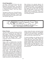
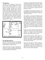
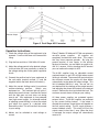
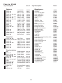
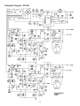
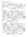
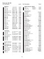
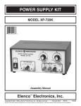
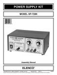
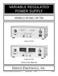
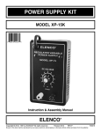
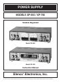
POWER SUPPLY
MODELS XP-660 / XP-760
Variable Regulated
Model XP-660
Model XP-760
Instruction Manual
Elenco Electronics, Inc.
®
Copyright © 2005, 1990 by Elenco® Electronics, Inc. All rights reserved.
Revised 2005
REV-H
No part of this book shall be reproduced by any means; electronic, photocopying, or otherwise without written permission from the publisher.
753660
Specifications for Model XP-660 @ 120VAC input
Input Voltage
Output Voltage
Output Current
Load Regulation
Line Regulation
Ripple RMS
Current Protection
Short Protection
Output Impedance
0-20V Supplies
5V Supply
110-135VAC 60 Hertz
0-20VDC Variable
0-1A over 0-20V range
Less than .1V over 0-20V range
Less than .1V 110V to 130V
Less than 5mV
.05 to 1A Variable current limiting
.05 to 1A current limit
.1 ohms
Same
5VDC + .1V
0-5A
Less than .15V
Less than .15V
Less than 10mV
Current foldback
Current foldback
.03 ohms
Specifications for Model XP-760 @ 120VAC input
Input Voltage
Output Voltage
Output Current
Load Regulation
Line Regulation
Ripple RMS
Current Protection
Short Protection
Output Impedance
0-20V Supplies
5V Supply
110-135VAC 60 Hertz
0-20VDC Variable
0-1A over 0-20V range
Less than .1V over 0-20V range
Less than .1V 110V to 130V
Less than 5mV
.05 to 1A Variable current limiting
.05 to 1A current limit
.1 ohms
Same
5VDC + .1V
0-5A
Less than .15V
Less than .15V
Less than 10mV
Current foldback
Current foldback
.03 ohms
-1-
Circuit Description
The Elenco® XP-660 and XP-760 use the same
basic power and regulator circuit. The only
difference is in the display function. The XP-660 has
two 0-1mA analog meters. These meters convert to
a voltmeter by placing a 20kΩ resistor in series or
an ampmeter by placing a .39Ω shunt resistor
across the meter.
When referring to the schematic diagrams, the
circuit components associated with each supply can
be identified by its number. The 5V supply begins
with 100. The 0-20V Power One Supply begins with
300 numbers and the 0-20V Power Two Supply
begins with 200 numbers. The basic circuit of these
supplies consist of 1) The power source, 2) The
regulator and 3) The readout circuit. These circuits
are shown in Figure 1 and will be discussed in detail
in the following paragraphs.
The Model XP-760 has two 3 1/2 digit LED meters.
Voltage is read by connecting the meter to a voltage
divider on the power supply output. Current is read
by connecting the meter to a shunt resistor in series
with the power supply output.
Figure 1 Block Diagram of 0-20V Power Supply
Power Source
collector voltage will increase, returning the output
voltage to very near its original value. The high gain
is essential to the output voltage. Diode D309 is
added to prevent drift with temperature changes
and to allow the output voltage to go to zero.
The power supply for Models XP-660 and XP-760
consists of a transformer with four isolated step
down windings. Connected to each winding is a
diode bridge and a filter capacitor. The components
on the Power One Supply are diodes D301, D302,
D303, D304 and capacitor C304.
These
components convert the 120VAC input to 25VDC.
To protect the regulator from overloads and short
circuits, transistor Q306 is added. Whenever the
voltage drops across resistor R309 reaches .6V,
transistor Q306 will conduct and lower the collector
voltage of amplifier Q305. To obtain variable current
limiting, transistor Q306 is prebiased via resistor
R309 and VR301 (see XP-660 schematic). This will
allow the output current limit between .05 and 1
amp. Transistors Q307 and Q308 are added to light
the overload LED.
0-20V Regulators
Figure 2 shows a simplified circuit of the 0-20V
regulator circuit. This circuit consists of a high gain
amplifier transistor Q305. The gain of this stage is
over 100,000 because of its extremely high load
impedance. This load consists of a current source
transistor Q301 and its biasing circuit. The effective
resistance of this circuit is over 500,000 ohms.
Transistor Q302 is a power device that controls the
output current. Transistors Q303 and 304 are
emitter followers used to prevent loading of the
current source. Q301, Q302, Q305 and VR303 form
a closed negative feedback loop. If you analyze this
loop you will find that when the output voltage goes
down due to increase output current, the voltage at
the base of transistor Q305 goes negative. This
reduces the current in transistor Q305 and thus the
-2-
5V Regulator
Timing for the overall operation of the A/D converter
is derived from a 40kHz external oscillator. The IC
divides this frequency by four and the resulting clock
pulses are used to drive its decade counters. It is
then further divided to form three convert-cycle
phases. The final readout is clocked at about 2.5
readings per second.
The circuit of the 5V regulator is shown on the
schematic with components beginning with number
100. The heart of the regulator is IC1. This IC
contains the same basic circuit as the 0-20V
regulator, previously described (see schematic
diagram of XP-660). Transistor Q102 is the pass
transisitor that controls the output current. Transistor
Q101 is used to increase the impedance of the pass
transistor. Resistor R104 senses the current and
shuts down the IC if the current exceeds 5 amps.
The regulator features a current foldback circuit
which reduces the current to less than 1 amp when
the output is shorted. Resistors R105 and R106 form
the current foldback circuit. Resistors R102 and
R103 are added to form a stable 3.9V reference
voltage for the IC to operate.
The digitized data is presented to the display as four
decoded digits (seven segments) plus polarity. The
decimal point position on the display is selected by
the Volts/Amps switch.
A/D Converter - Any given measurement cycle
performed by the A/D converter can be divided into
three consecutive time periods, autozero (AZ),
integrate (INTEG) and read. A counter determines
the length of the time periods. The integrate period
is fixed at 1,000 clock pulses. The read period is a
variable time that is proportional to the unknown
input voltage. It can vary from zero counts for zero
input voltage to 2,000 counts for a full scale input
voltage. The autozero period varies from 1,000 to
3,000 counts. For an input voltage less than full
scale autozero gets the unused portion of the read
period.
During the autozero cycle the accumulated offset
voltage errors in the converter are measured and
stored as a voltage on the external autozero
capacitor. This voltage is used to correct for the
offset voltage errors during the read cycle.
During the INTEG cycle the INTEG capacitor is
charged up for 1,000 clock pulses (100ms.), see
Figure 3. The charging rate is determined by the
unknown input voltage. At the end of the integrate
cycle the voltage on the capacitor is proportional to
the unknown input voltage.
Figure 2 Simplified Regulator Circuit
XP-760 Digital Meters
Meter operation centers around the 7107 integrated
circuit (IC). This chip contains a dual slope A/D
(analog to digital) converter, display latches, seven
segment decoder, and display drivers.
During the read cycle the INTEG capacitor is
discharged at a constant rate. The time required for
the discharge is therefore proportional to the
unknown input voltage. This time is converted to a
digital format by counting the number of clock
pulses that occur during the discharge.
The input of the 7107 IC is fed to an A/D converter.
Here the DC voltage is changed to a digital format.
The resulting signals are processed in the decoders
to light the appropriate LED segments.
-3-
Counter Output
Figure 3 Dual Slope A/D Converter
Operation Instructions
Elenco® Models XP-660 and XP-760 are extremely
versatile power supplies.
All supplies are
completely isolated from each other. This means
that they have separate grounds. By tying the
ground terminal of one supply to the positive
terminal of the other, you can obtain an output of 040V @ 1 ampere. Also by stacking the 5V terminal
you can increase the output to 45V.
1) Check the voltage rating of the equipment to be
powered. Care must be taken not to exceed this
rating.
2) Plug the line cord into a 120V 60Hz AC outlet.
3) Adjust the voltage control to the desired voltage.
Load variation will have practically no effect on
the voltage setting due to the special regulation
circuit.
The 0-20V supplies have an adjustable current
overload feature, a red LED will light when current
limiting is activated. The current limit control adjusts
the maximum current the supply will allow before
automatically turning down the output voltage. This
limit is between 50mA to 1 amp. You can set it to
your desired limit by shorting out the output terminal
and adjusting the current limit control to the desired
current. Remove the short and attach the load. The
maximum current drawn will be per your setting.
4) Connect the positive lead of your equipment to
the red output terminal marked (+) and the
negative lead to the black terminal marked (–).
5) Adjust the current limiting control to maximum
counter-clockwise position.
Switch your
equipment on. The overload light will glow if
excessive current is drawn. Increase this control
until the light goes out and stays out during
normal use. Your equipment is now protected
from high current surges. An alternate method
of adjusting current limiting is to short the output
and adjust the current to a desired value.
Remove the short. This will now limit the current
to your setting.
All three power supplies are protected against
external shorts. The 0-20V supplies are protected
by the current limiting feature. If the output is
shorted the maximum current drawn will depend on
the limit control setting. The 5V supply features a
current foldback circuit. This circuit will limit the
output current to less than 1 amp. When the short
is removed, the output voltage will automatically
reset to 5V.
6) Meters can be switched to read voltage or
current.
-4-
Safety Precautions
Variable 0-20VDC Regulator
Calibration
Certain safety procedures must be observed when
this power supply is used with external circuits that
are connected to AC power lines. There is always
some danger when working with electrical
equipment or circuits that operate at hazardous
voltages. You should thoroughly familiarize yourself
with the equipment before working on it. High
voltage may appear at unexpected points in
defective equipment.
1) Connect an accurate digital meter to the output
of the 0-20V supply.
2) Set the voltage pot to maximum position.
3) Adjust the variable resistor VR302 of Power One
Supply for 20.0V. Adjust VR203 for Power Two
Supply.
Digital Meter Calibration
for Model XP-760
The Elenco® power supplies are equipped with three
wire line cords which ground the chassis to power
line cord. DO NOT CUT OFF OR DISABLE THE
GROUND PLUG.
1) Note the small pot (R2) on the top of each
meter’s PC board. This is the GAIN pot which
controls the accuracy of the meter.
2) To set the accuracy of the meter you need
another very accurate digital meter. Connect
this meter to measure the voltage on the output
terminals of the supply under adjustment. Set
the output to 18VDC. Set the Volts/Amps switch
to Volts and adjust the GAIN pot for 18.0 on the
XP-760 meter.
The power supply secondary circuits are isolated
from the 120V primary circuit via the power
transformer. When working with other equipment, this
may not always be the case. Always be familiar with
the equipment rating. Keep in mind that defective
equipment can have dangerous voltages at
unexpected points. CAUTION: When removing the
cover for fuse replacement, always disconnect the
power cord from the AC socket. Service repair should
only be done by qualified personnel who are
knowledgeable of electrical hazards.
3) To set the accuracy of the current measurement
connect a suitable load to the output and
connect the accurate digital meter to measure
the current in the load. Set the Volts/Amps
switch to Amps. Set the output current to 0.8
amps. Adjust VR304 (Power One Supply) or
VR204 (Power Two Supply) for a reading of 0.8
on the XP-760 meter.
Maintenance and Calibration
The Elenco® Models XP-660 and XP-760 have been
designed and manufactured to require no routine
maintenance. The circuits are protected by design
from external shorts or overloads. The following
information is provided in the event the supply requires
service or re-calibration.
Fixed 5VDC Regulation Calibration
1) Connect an accurate digital meter to the output
of the 5V supply.
2) Adjust the variable resistor VR101 to read
5.0VDC.
-5-
Parts List XP-660
Qty. Description
Part #
Qty. Description
Resistors
2
2
2
4
2
4
3
4
2
2
2
1
2
3
1
2
2
3
2
2
R105
R213, 313
R210, 310
R208, 209, 308, 309
R211, 311
R202, 203, 302, 303
R101, 222, 322
R206, 214, 306, 314
R201, 301
R205, 305
R215, 315
R102
R217, R317
R103, 204, 304
R104
R216, 316
R218, 318
VR101, 202, 302
VR201, 301
R203, 303
Miscellaneous
.14Ω 5% 5W
.39Ω 5% 2W
68Ω 5% 1/4W
200Ω 5% 1/4W
270Ω 5% 1/4W
470Ω 5% 1/4W
1kΩ 5% 1/4W
1.2kΩ 5% 1/4W
1.2kΩ 5% 1/2W
2kΩ 5% 1/4W
3.3kΩ 5% 1/4W
10kΩ 5% 1/4W
20kΩ 1% 1/4W
22kΩ 5% 1/4W
27kΩ 5% 1/4W
100kΩ 5% 1/4W
200Ω Trim Pot LD
5kΩ Trim Pot SU
200Ω Pot Panel
5kΩ Pot Panel
101405
103911
126800
132000
132700
134700
141000
141200
141201
142000
143300
151000
152030
152200
152700
161000
191320
191451
192320
192450
.001µF Disc
100µF Lytic 25V
100µF Lytic 35V
100µF Lytic 25V
(axial)
2200µF Lytic 25V
3300µF Lytic 50V
4700µF Lytic 16V
231036
281045
281046
281055
Diode bridge 6A
Diode 1N4001
Diode 1N4002
310148
314001
314002
Diode 1N4148
Diode Zener 1N5240 10V
Transistor MPSA70
Transistor TIP120
Transistor 2N3055
Transistor MPS5172
314148
315240
320070
320120
323055
325172
1
1
1
2
1
2
1
1
1
2
4
1
3
7
7
3
1
4
2
6
1
4
1
4
4
8
1
4
4
3
4
6
11
1
5
2
4
1
1
1
1
1
Capacitors
3
5
2
3
C104, 206, 306
C103,201,202,301,302
C205, 305
C105, 210, 310
2 C203, 303
2 C204, 304
2 C101, 102
292225
293347
294744
Semiconductors
1 BR1
2 D211, 311
15 D101, 201-206, 209,
D301-306, 309
4 D207, 208, 307, 308
2 D210, 310
4 Q201, 207, 301, 307
1 Q101
3 Q102, 202, 302
8 Q204-206, 208,
Q304-306, 308
2 Q203, 303
1 IC
2 LED201, 301
Part #
Transistor MPS6521 326521
IC MC1723
331723
LED Red
350001
-6-
Transformer
PC Board
Fuse 1.5A Slow Blow
Switch slide DPDT
Switch Illuminated
Volt/Amp Meter
Cover
Chassis
Heatsink 1 TO-3
Heatsink Ham Rod
Knob
Bushing Strain 3 wire
Binding Post Black
Binding Post Hex Nut
Binding Post Lockwasher
Binding Post Red
Binding Post Green
PCB Support
LED Lens
Cable Ties
Rivet .122
Screw M3 x 0.5 x 5mm phillips, black
Screw 6-32 x 1/2”
Screw 8-32 x 3/8”
Screw 6 x 3/8” Truss, AB
Screw 6 x 3/8” AB
Nut 6-32 Small
Nut 8-32
Nut 7mm
Washer Flat #8
Washer 8mm
Washer 1/8”
Lockwasher 5/16”
Lockwasher #6
Lockwasher #8 Ext.
Lug ground
Lug Solder #8
Fuse Holder Lower Body
Fuse Holder Nut
Fuse Holder Upper Body
Fuse Holder Washer
IC Socket 14-Pin
440660
512010
520150
541111
541204
571020
611060
611660
615001
615100F
622009
624003
625031
625031HN
625031LW
625032
625033
625001
626014
628982
632211
640300
641665
641840
642652
642660
644601
644800
644101
645008
645101
645600
646101
646600
646828
661001
661002
663005LB
663005N
663005UB
663005W
664014
Schematic Diagram XP-660
-7-
Schematic Diagram XP-760
-8-
Parts List XP-760
Qty. Description
Part #
Qty. Description
.14Ω 5% 5W
.39Ω 5% 2W
68Ω 5% 1/4W
100Ω 5% 7W
200Ω 5% 1/4W
270Ω 5% 1/4W
470Ω 5% 1/4W
910Ω 5% 1/4W
1kΩ 5% 1/4W
1.2kΩ 5% 1/4W
1.2kΩ 5% 1/2W
1.5kΩ 5% 2W
2kΩ 5% 1/4W
3.3kΩ 5% 1/4W
10kΩ 5% 1/4W
22kΩ 5% 1/4W
27kΩ 5% 1/4W
100kΩ 5% 1/4W
1MΩ 5% 1/4W
200Ω Pot LD
5kΩ Pot SU
10kΩ Pot SU
200Ω Pot Panel
10kΩ Pot Panel
.01Ω Shunt Wire
101405
103911
126800
131017
132000
132700
134700
139100
141000
141200
141201
141503
142000
143300
151000
152200
152700
161000
171000
191320
191451
191516
192320
192511
897120
1 IC101
2 IC201, 301
2 LED201, 301
Disc .001µF Z5V
Disc .1µF
Lytic 4.7µF 50V Radial
Lytic 100µF 25V
231036
251010
264747
281045
Lytic 100µF 25V Axial
Lytic 220µF 25V
Lytic 2200µF 25V
Lytic 3300µF 50V
Lytic 4700µF 16V
281055
282245
292225
293347
294744
Diode bridge 6A
Diode 1N4001
310148
314001
Diode 1N4148
Diode Zener 1N5240 10V
Transistor MPSA70
Transistor 2N3055
Transistor MPS5172
314148
315240
320070
323055
325172
Trans. 6121/1061
Trans. MPS6521
326121
326521
Resistors
2
2
2
2
4
2
4
2
3
4
2
2
2
2
1
3
1
2
2
2
1
2
2
2
2
R105
R213, 313
R210, 310
R207, 307
R208, 209, 308, 309
R211, 311
R202, 203, 302, 303
R219, 319
R101, 222, 322
R206, 214, 306, 314
R201, 301
R307, 312
R205, 305
R215, 315
R102
R103, 204, 304
R104
R216, 316
R217, 317
VR201, 301
VR101
VR302, 303
VR204, 304
VR202, 203
R220, 320
Semiconductors (Con’t)
3
2
2
2
2
C104,
C209,
C207,
C103,
C301,
C105,
C208,
C203,
C204,
C101,
206,
309
307
201,
302,
210,
308
303
304
102
306
202, 205
305
310
Semiconductors
1 BR1
17 D201-206, 209, 211
D301-306, 309, 311
4 D207, 208, 307, 308
2 D210, 310
4 D201, 207, 301, 307
4 Q102, 202, 302
8 Q204, 206, 208,
Q304-306, 308
1 Q101
2 Q203, 303
MC1723
MC7805CT
LED Red
331723
337805
350001
Miscellaneous
2
1
1
1
2
1
1
1
1
2
2
4
1
4
3
7
7
3
1
2
5
7
2
4
4
8
4
1
1
4
3
4
4
7
1
5
4
2
1
4
1
1
1
1
1
Capacitors
3
2
2
7
Part #
-9-
LED Display
Transformer
PC Board
Fuse 1.5A Slow Blow
Switch 3PDT
Switch Illuminated
Cover
Chassis
Heat Sink 5V
Heat Sink Clip On
Heat Sink 20V
Knob Push On
Bushing
PCB Support
Binding Post Black
Binding Post Lockwasher
Binding Post Hex Nut
Binding Post Red
Binding Post Green
LED Lens Red
Cable Tie
Rivet .122
Screw 6-32 x 1/2”
Screw 8-32 x 3/8”
Screw 6 x 3/8” Truss, AB
Screw 6 x 3/8”
Nut Hex 7mm
Nut 6-32
Nut 6-32 Small
Nut 8-32
Washer Flat #8
Flat Washer Pot 8 x 14mm
Washer Fiber #4
Flat Washer 1/4” OD
Lockwasher #6
Lockwasher #8 Ext.
Lockwasher Pot 3/8”
Lug Ground
Butt Connector
Feet
Fuse Holder Lower Body
Fuse Holder Nut
Fuse Holder Upper Body
Fuse Holder Washer
Line Cord 3 Wire
355614MI
440660
512010
520150
541047
541204
611060
611760
615001S
615005
615100F
622009
624003
625002
625031
625031LW
625031HN
625032
625033
626014
628982
632211
641665
641840
642652
642660
644101
644600
644601
644800
645008
645101
645404
645600
646600
646828
646900
661001
661100
662001
663005LB
663005N
663005UB
663005W
862105
WARRANTY POLICY
All of our instruments have been tested and conform to our rigid requirements on
performance and durability, they are guaranteed to be free of defects in
workmanship, materials and construction for a period of 2 years. If this product
should fail in normal use within the first 3 months from the date of purchase, Elenco®
will repair or replace the unit at no cost. For the remainder of the warranty period, a
nominal service charge is required to cover shipping and handling. Elenco® will either
repair or, at its sole option, replace any part except for fuses, probes, lamps, batteries
and other optional materials which are defective in either workmanship or material
under normal and proper use.
This warranty does not cover equipment which has been tampered with in any way,
or damage caused by accident, negligence, alteration, misapplication or
unassembled products. This product must be returned transportation prepaid,
properly packed and insured, and must include proof of purchase. This warranty
applies only to the original purchaser. NO OTHER WARRANTIES ARE
EXPRESSED OR IMPLIED. ELENCO® IS NOT LIABLE FOR CONSEQUENTIAL
DAMAGES. Please contact Elenco® for further instructions before returning your
instrument.
Direct all warranty inquiries to:
Elenco® Electronics, Inc. • Service Department
150 Carpenter Avenue, Wheeling, IL 60090 • Phone: (847) 541-3800
-10-
Elenco® Electronics, Inc.
150 Carpenter Avenue
Wheeling, IL 60090
(847) 541-3800
Fax: (847) 520-0085
Web site: www.elenco.com
e-mail: [email protected]