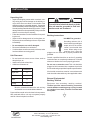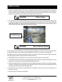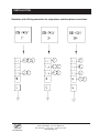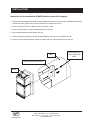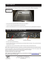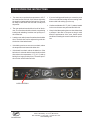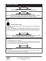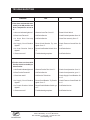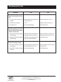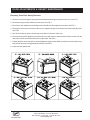
1
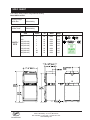
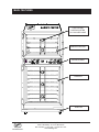
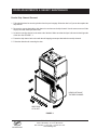
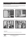
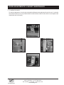
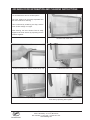
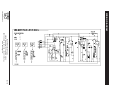
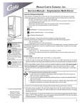
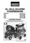
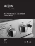
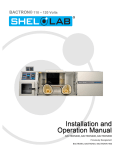
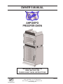
OWNER’S MANUAL
AHPO/EPO
PROOFER OVEN
IMPORTANT INFORMATION
READ BEFORE USE
PLEASE SAVE THESE INSTRUCTIONS
Duke Manufacturing Co.
2305 N. Broadway • St. Louis, MO 63102
800.735.3853 • 3.231.1130 • 314.231.5074 Fax
www.dukemfg.com
502821F
CONTENTS
Manufacturing Introduction
Safety Instruction
Spec Sheets
Main Features
Installation Instructions
Oven Start-Up
Proofer Operating Instructions
Oven Operating Instructions
Care and Cleaning
Troubleshooting
Door Adjustments and Gasket Maintenance
Air-wash door Information and Cleaning Instructions
Bulb Mounting Details
Parts List and Illustrations
Wiring Diagrams
Customer Assistance
Manufacturers Introduction
2
3
4
5
6-9
10
10-11
12-13
14
15-16
17-22
23
24
25-27
28
29
Supplier Name:
Address:
The Duke AHPO or EPO Proofer Oven were developed
in response to Customer’s need for uniform baking
capabilities to provide consistently high, “just baked”
bread quality.
Model #:
The Duke Proofer Oven utilizes Duke’s unique directional
convection airflow technology that provides even heat
distribution and a uniform bake without the need for
turning pans during the bake cycle. This enhances the
quality and consistency of the baked products while
reducing food scrap/waste and simplifying operating
procedures.
The low profile oven won’t block the view of menu boards
and will easily roll through a standard height door. The
oven and proofer doors are field reversible with a drip
channel on the proofer door to prevent water from
dripping on the floor.
Full width doors on the oven and proofer help to display
and merchandise fresh baked bread to the customer.
The controls are simple to operate, there are two timers
for independent timing of the proofer and oven.
The full width oven and proofer cavity will accept
standard ½ size or full size sheet pans.
Duke Manufacturing Co.
2305 N. Broadway
St. Louis, MO 63102
AHPO-6/18-208
AHPO-6/18-230
Note:“230V” can be used
for 220-240V
1Ph or 3Ph
3N (3Ph w/neutral)
AHPO-6/18-400
EPO-3/9-208
Note:“230V” can be used
for 220-240V
EPO-3/9-230
1Ph or 3Ph
3N (3 Ph w/neutral)
EPO-3/9-400
Serial #:
Date
Received:
Date
Installed:
Telephone:
Fax:
Service
Referral #:
Local
Service
Name:
Local
Service #:
(800) 735-DUKE (3853)
(314) 231-1130
(314) 231-5074
Duke Manufacturing Co.
2305 N. Broadway • St. Louis, MO 63102
800.735.3853 • 3.231.1130 • 314.231.5074 Fax
www.dukemfg.com
2 of 29
IMPORTANT SAFETY INSTRUCTIONS
Throughout this manual, you will find the following safety words and symbols that signify important safety issues
with regards to operating or maintaining the equipment.
WARNING
WARNING
GENERAL WARNING. Indicates information important to the proper operation of
the equipment. Failure to observe may
result in damage to the equipment and/
or severe bodily injury or death.
ELECTRICAL WARNING. Indicates information relating to possible shock hazard.
Failure to observe may result in damage
to the equipment and/or severe bodily
injury or death.
CAUTION
WARNING
GENERAL CAUTION. Indicates information important to the proper operation of
the equipment. Failure to observe may
result in damage to the equipment.
In addition to the warnings and cautions in this manual,
use the following guidelines for safe operation of the unit.
• Read all instructions before using equipment.
• For your safety, the equipment must be furnished
with a properly grounded cord connector. Do not
attempt to defeat the grounded connector.
• Install or locate the equipment only for its intended
use as described in this manual.
• Do not use corrosive chemicals in this equipment.
• Do not operate this equipment if it has a damaged
cord or plug, if it is not working properly, or if it has
been damaged or dropped.
• This equipment should be serviced by qualified personnel only. Contact the nearest Duke authorized
service facility for adjustment or repair.
• Do not block any openings on the unit.
• A minimum clearance of 6” (152,4 mm) from the top
of the unit to the ceiling must be provided.
• This appliance must be secured to building structure
(Restraining Device Kit).
• Keep cord away from heated surfaces.
• To prevent tipping, securely attach unit to the wall
using brackets provided.
HOT SURFACE WARNING. Indicates information important to the handling of
equipment and parts. Failure to observe
caution could result in personal injury.
The following warnings and cautions appear throughout
this manual and should be carefully observed.
• Turn the unit off, disconnect the power source and
allow unit to cool down before performing any service
or maintenance on the unit.
• The procedures in this manual may include the use
of chemical products. You must read the Material
Safety Data Sheets before using any of these products.
• The unit should be grounded according to local electrical codes to prevent the possibility of electrical
shock. It requires a grounded receptacle with separate electrical lines, protected by fuses or circuit
breaker of the proper rating.
• All electrical connections must be in accordance with
local electrical codes and / or any other applicable
codes.
• Disposal of the unit must be in accordance with local environmental codes and/or any other applicable
codes.
SAVE THESE INSTRUCTIONS
Duke Manufacturing Co.
2305 N. Broadway • St. Louis, MO 63102
800.735.3853 • 3.231.1130 • 314.231.5074 Fax
www.dukemfg.com
3 of 29
SPEC SHEET
U.S. Patent. Other US and Foreign Patents Pending
Model AHPO or EPO
Shipping Weight:
Carton Box
625lbs/284 Kg
Shipping Weight:
Wooden Crate
760lbs/345 Kg
AHPO /
EPO
Volts
Phase
208
208
230 (220-240)
230 (220-240)
230 (220-240)
230 (220-240)
400 (380-415)
400 (380-415)
1
1
1
1
3
3
3N
3N
Hz
Watts
Amps
60
50
60
50
60
50
60
50
6650
6650
6650
6650
6650
6650
6650
6650
32.0
32.0
32.0
32.0
16.7
16.7
16.7
16.7
Duke Manufacturing Co.
2305 N. Broadway • St. Louis, MO 63102
800.735.3853 • 3.231.1130 • 314.231.5074 Fax
www.dukemfg.com
4 of 29
MAIN FEATURES
LOW VOLTAGE
LIGHTING SYSTEM
12V HALOGEN LAMP
CONVECTION OVEN
CONTROL PANEL
PROOFER
DRIP PAN
Duke Manufacturing Co.
2305 N. Broadway • St. Louis, MO 63102
800.735.3853 • 3.231.1130 • 314.231.5074 Fax
www.dukemfg.com
5 of 29
INSTALLATION
Unpacking Unit
•
•
•
•
•
•
•
Inspect the shipping carton and/or container, carefully noting any exterior damage on the delivery receipt, which was not evident on the outside of the
shipping container (concealed damage). Contact the
carrier immediately and file a damage claim with them.
Save all packing materials when filing a claim. Freight
damage claims are the responsibility of the purchaser
and are not covered by the warranty.
Follow the instructions on the Carton Box for unpacking the unit.
Inspect unit for damage such as, broken glass, etc.
Report any dents or breakage to source of purchase
immediately.
Do not attempt to use unit if damaged.
Remove all materials from unit interior.
If unit has been stored in extremely cold area, wait a
few hours before connecting power.
Unit Placement
•
•
•
Do not install unit next to source of heat, such as
deep fat fryer, etc.
Install unit on level surface floor.
A Minimum Clearance of:
Unit
Clearance
Right Side
0”
Left Side
0”
Rear
0”
Ceiling
6”
WARNING
To avoid risk of electrical shock or death,
this unit must be grounded or field connection must not be altered.
Earthing Instructions
Unit MUST be grounded.
Grounding reduces risk of
electric shock by providing an
escape wire for the electric
current if an electrical short
occurs. When using an appropriate plug it must be
plugged into an outlet that is properly installed and
grounded.
Consult a qualified electrician or servicer if grounding
instructions are not completely understood, or if doubt
exists as to whether the oven is properly grounded.
Do not use an extension cord. This unit should be
plugged or field connected into a separate circuit with
the electrical rating as provided in product specifications.
All electrical connections must be in accordance with
local electrical codes and/or any other applicable codes.
External Equipotential
Earthing Terminal
Must be maintained between the unit and any
combustible or non-combustible substance.
Equipment has secondary earthing terminal.
Terminal provides external earthing connection
used in addition to earthing prong on plug. Located
on outside of oven back, terminal is marked with
this symbol.
Proper airflow around unit cools electrical components.
With restricted airflow, unit may not operate properly
and life of electrical parts is reduced.
Duke Manufacturing Co.
2305 N. Broadway • St. Louis, MO 63102
800.735.3853 • 3.231.1130 • 314.231.5074 Fax
www.dukemfg.com
6 of 29
INSTALLATION
1. Compare the voltage and phase from the oven specification label to the power supply for the oven and call Duke
if there is a difference. If the phase is wrong, a qualified service technician can change the wire connections
inside the oven to correct the problem. See the illustration on page 4 for phase conversions. If the voltage is
wrong, the heat elements must be changed. Call Duke to get new elements.
WARNING
Risk of Injury
2. This appliance must be secured to building structure. A restraining device kit (#153586) was provided with the
unit to limit the movement of the appliance without depending on or transmitting stress to the electrical conduit.
Installation instruction is in the kit. Permanent installation of the unit requires that the utility connection be of
sufficient length to allow the equipment to be moved for cleaning.
RESTRAINING DEVICE
KIT (PART # 153586)
WARNING
Risk of Electric Shock
This Restraining Device MUST always be connected when the Appliance is in Service. Disconnect for movement,
servicing and or cleaning, then reconnect when the appliance has been returned to its normal position.
The appliance shall be installed using flexible conduit or equivalent to meet the local electrical codes and shall be
of sufficient length to allow the equipment to be moved for cleaning.
3. IMPORTANT: A minimum clearance of 6” from the top of unit to the ceiling must be provided.
4. TO PREVENT FROM TIPPING: Unit must be permanently attached to wall using wall-mounting brackets. Refer
page 9 for the instructions on Installation of Wall Brackets to the wall.
5. Check the swing of the door. The hinge side can be changed by following the instructions on the following pages.
The door swing direction can be changed in the field after you have a new drip channel for the proofer door. Call
Duke to get the new drip channel for the proofer door.
6. Check the door seal and make sure both doors close completely. If they do not close and seal properly, call
Duke for assistance.
7. Place the wire racks in the oven and proofer.
Duke Manufacturing Co.
2305 N. Broadway • St. Louis, MO 63102
800.735.3853 • 3.231.1130 • 314.231.5074 Fax
www.dukemfg.com
7 of 29
INSTALLATION
Illustration of the Wiring connection for single phase and three phase connections.
Duke Manufacturing Co.
2305 N. Broadway • St. Louis, MO 63102
800.735.3853 • 3.231.1130 • 314.231.5074 Fax
www.dukemfg.com
8 of 29
INSTALLATION
Instruction for the installation of Wall Brackets to the wall for tipping!
1. Mount the Wall Mounting Bracket with screws provided to the Proofer Oven & extend the Wall Mounting Bracket
towards the wall by sliding it thru the slot provided. Do not tighten the screws.
2. Mark on the Wall & Drill in the Wall for fixing anchors for screws.
3. Insert the wall anchors into the already drilled holes on the wall.
4. Butt the Wall Mounting Bracket against the wall.
5. Insert the screws provided into the Wall Mounting Bracket to firmly secure it against the wall.
6. Please re-ensure that the Bracket is firmly secured to the wall. Tighten the screws into the unit.
WALL
HOLE DRILLED IN
WALL FOR FIXING
BRKT
WALL MOUNTING BRACKET
WALL
Duke Manufacturing Co.
2305 N. Broadway • St. Louis, MO 63102
800.735.3853 • 3.231.1130 • 314.231.5074 Fax
www.dukemfg.com
9 of 29
OVEN START-UP
Have a qualified service technician or electrician connect the oven to the power supply. Check the door seal and
make sure both doors close completely. If they do not close and seal properly, call Duke for assistance
WATER LEVEL
INDICATOR
FIGURE - 1
•
Fill the proofer water pan about half full of clean water. See FIGURE - 1.
•
Turn the oven and proofer power switches to the ON position.
•
Set the oven thermostat at 350°F (175°C), the proofer thermostat at 105°F (40°C), and the proofer humidity at #3.
PROOFER OPERATING INSTRUCTIONS
PROOFER CONTROLS
OVEN CONTROLS
•
All of the indicator lights should be on.
•
Check to make sure that the oven and Proofer fans are running. Open the oven door. The oven fan should stop.
Close the door to continue.
•
Set both timers to 20 minutes and check to make sure they time down and the buzzers work.
NOTE: When using timer for less than 10 minutes, you must turn the timer knob past 10 and then set time.
If there are any problems, call the service department at Duke for assistance before you call a service agency. If the
problem is an operator or procedural error you will be liable for the service charges.
Allow the oven and proofer to pre-heat for at least 30 minutes.
Your Duke Proofer Oven is now ready to operate.
NOTE: Start-Up Form #502854 is available for you to fill out from our website www.dukemfg.com. Please
print and Fax to Duke at 314-231-2460.
Duke Manufacturing Co.
2305 N. Broadway • St. Louis, MO 63102
800.735.3853 • 3.231.1130 • 314.231.5074 Fax
www.dukemfg.com
10 of 29
PROOFER OPERATING INSTRUCTIONS
Make sure the humidity pan has fresh clean water in it. Fill it with warm water to get the best performance. A regular
check of the water level is recommended during operation. Add water as required.
•
Turn the proofer power switch on and set the proofer heat to the desired temperature. A good starting temperature is 105°F.
•
•
The light above the heat thermostat will be on until the proofer has heated to the set temperature.
•
•
•
•
•
•
•
•
•
You may need to adjust this temperature depending on your results. Do not turn on the proofer humidity at this
time.
After the proofer has been heating for 20 minutes, turn the humidity switch to a setting of #3 or 4.
You may need to adjust this setting depending on your results.
When a light fog appears on the door glass the proofer is ready to load with dough.
The humidity setting is too high if water is running down the door glass.
If the door glass does not fog then the humidity setting is too low.
Load the proofer with bread dough and set the timer for 50 - 60 minutes.
You may need to adjust the time depending on the type of dough and your results.
When it rises to 75 - 80 % of it’s final size, it is ready to bake.
Since the proofer can hold more pans of bread than the oven can bake, stagger the loading in increments of the
oven bake time. This will prevent over proofing of the bread remaining in the proofer after the first load is moved
to the oven.
•
If there is excessive humidity on the door glass it is probably caused by a humidity setting that is too high or by
having the humidity on when there is no dough loaded in the proofer.
•
•
Turn the proofer off and remove the bottom panel.
Remove excess water that has accumulated in the bottom of the proofer.
DO NOT…
•
Run the proofer humidity without a load of dough.
It is OK to leave the proofer heat on to maintain the temperature, but turn the humidity off if the proofer is empty.
•
Let the dough dry out while it is thawing.
Dough that is too dry will not fully rise in the proofer and may crack.
•
Over-proof the dough
Excessive proofing will cause the bread to collapse after it has been baked. Make sure to adjust the proofing
time to prevent over-proofing.
•
Under-proof the dough
If the bread is under-proofed it will not bake to the proper finished size and will have a dense cell structure.
•
Proof frozen dough
Make sure the dough is thawed properly before loading it into the proofer. The dough should be soft and moist
with the center thawed.
DO…
•
Watch the proofing process carefully and make adjustments if necessary.
Duke Manufacturing Co.
2305 N. Broadway • St. Louis, MO 63102
800.735.3853 • 3.231.1130 • 314.231.5074 Fax
www.dukemfg.com
11 of 29
OVEN OPERATING INSTRUCTIONS
•
•
Turn the oven on and set the temperature to 350° F
for bread and for Deli rolls. If this is done right after
the proofer is loaded with the first load, the oven will
be ready to bake when the first load is ready from
the proofer.
The oven preheat time should be from 20 to 30 minutes. The oven door should be closed, except during
loading and unloading. Load the oven quickly to reduce heat loss.
•
Load the oven with 6 pans of bread and set the bake
timer. The bake time can be adjusted to get the desired color of the baked bread.
•
If the baking results are uneven or too dark, reduce
the temperature and extend the bake time.
•
If the bread is too dark, reduce the bake time. If the
bake time is reduced and the bread is still too dark
then reduce the temperature 15° F (10° C) and try
baking for a longer period of time. The same procedure can be used to bake Deli rolls.
•
If you are baking partial loads try to center the pans
in the oven and start loading the oven starting at the
bottom shelf and working up to the top.
•
Cookies are baked at 325° F (163° C) and are loaded
in the oven the same way as bread and deli rolls.
•
Keep in mind that opening the oven door allows heat
to escape. If the door is left open too long it could
affect the performance of the oven. Under normal
conditions of loading the oven this will not be a problem.
OVEN CONTROLS
Duke Manufacturing Co.
2305 N. Broadway • St. Louis, MO 63102
800.735.3853 • 3.231.1130 • 314.231.5074 Fax
www.dukemfg.com
12 of 29
OVEN AND PROOFER TEMPERATURE CHECK
If the oven or proofer temperature calibration seems to be wrong, it can be checked before a service call is made.
It is important to follow the correct procedure to get an accurate reading. If the calibration is off it is recommended
that you first call Duke Manufacturing Co. and talk to the service department before you schedule a service call.
Calling Duke first can save you time and money by eliminating other problems before a service call is made.
The most important concern with temperature measurement is the accuracy of the thermometer and the location in
the oven cavity. Duke recommends an electronic temperature meter with a wire thermocouple.
1. Place the thermocouple at the geometric center of
the oven cavity. It can be fastened to the center of
the middle wire shelf.
5. The same steps can be used to check the proofer
temperature. The temperature control should be set
for 105° F and the normal variance is +/- 5° F
2. Start the oven and set the temperature control for
350° follow the oven to pre-heat for at least 45 minutes.
6. Loosen the small allen set screw on the side of the
knob. Adjust knob to the calibration temperature reading and tighten setscrew. Use the same procedure
for the proofer.
3. While watching the heat light on the control panel,
note the maximum and minimum temperatures
through several cycles.
4. The average temperature of several cycles is the calibration temperature. It is normal for this temperature
to have a variance of +/- 10° F.
THERMOCOUPLE AT
GEOMETRIC CENTER
OF OVEN CAVITY
Duke Manufacturing Co.
2305 N. Broadway • St. Louis, MO 63102
800.735.3853 • 3.231.1130 • 314.231.5074 Fax
www.dukemfg.com
13 of 29
CARE AND CLEANING
WARNING
Bottom and sides of warmer wells are very hot and cool slowly.
CAUTION
Electrical shock hazard. Do not wash with water jet or hose.
Do not use caustic cleaners, acids, ammonia products, abrasive cleaners, or abrasive
cloths. These can damage the stainless steel and plastic surfaces.
DAILY
CLEANING INSTRUCTIONS
1. Wipe down the interior and exterior of the Proofer Oven with warm water and mild detergent
using a soft cloth.
2. Clean Proofer water pan using mild detergent and warm water. Ensure all soap is rinsed
from the Oven and Proofer surfaces and water pan to avoid flavor transfer to the bread.
3. Open the Proofer door and run the Proofer with the heat on for at least 30 minutes to dry it.
CAUTION
Do not use caustic cleaners, acids, ammonia products or abrasive cleaners or cloths.
These can damage the stainless steel and door gaskets.
MONTHLY
1. Check door handle screws for tightness.
2. Clean the Bottom Area of the Proofer. Turn the Proofer off, wait 30 minutes and/or when the
area is cool to touch, then remove the bottom fan cover panel. Wipe clean all the surfaces
for any particles that have accumulated around this area.
WARNING
QUARTERLY
1. Check the door gasket seal on the Oven and Proofer for leaks. See the section on
Door Adjustments and Gasket Maintenance for directions.
Duke Manufacturing Co.
2305 N. Broadway • St. Louis, MO 63102
800.735.3853 • 3.231.1130 • 314.231.5074 Fax
www.dukemfg.com
14 of 29
TROUBLESHOOTING
Problem
Yes
No
1. Oven does not heat with oven
switch in the ON position and
Oven Temperature not set at
0°.
a.Are oven indicator lights on?
Observe Oven Fan. Go to “b”.
Reset Hi-limit Switch
b.Does Oven Fan work?
Call Duke Service.
Check Proofer Operation. Go to “d”.
c.Is Oven Door Securely
closed?
Call Duke Service.
Close Door securely. Go to “f”.
d.Is Supply Circuit Breaker
tripped?
Reset Circuit Breaker. Try oven
again. Go to “f”.
Check Fuses on Control Box. Go
to “f”.
e.Is Oven Breaker Switch
tripped?
Reset Oven Breaker Switch. Go to
“f”.
Call Duke Service.
f. Does oven work?
Troubleshooting complete.
Call Duke Service.
a.Are Proofer indicator lights on?
Observe Proofer Fan. Go to “b”.
Check Oven Operation. Go to “c”.
b.Does Proofer Fan work?
Call Duke Service.
Check Oven Operation. go to “c”.
c.Does Oven work?
Call Service Technician.
Check Supply Circuit Breaker. Go
to “d”.
d.Is Supply Circuit Breaker
tripped?
Reset Circuit Breaker. Try Proofer
again. Go to “f”.
Check Fuses on Control Panel. Go
to “e”.
e.Is Proofer Breaker Switch
tripped?
Reset Proofer Breaker Switch. go
to “f”.
Call Dukes Service.
f. Does oven work?
Troubleshooting complete.
Call Dukes Service.
2. Proofer does not heat with
Proofer Switch in the ON position Proofer
Duke Manufacturing Co.
2305 N. Broadway • St. Louis, MO 63102
800.735.3853 • 3.231.1130 • 314.231.5074 Fax
www.dukemfg.com
15 of 29
TROUBLESHOOTING
Problem
Yes
No
3. Oven/Proofer lights not working.
a.Is more than one light not
working?
Replace inoperative light bulbs and
recheck. Go to “b”.
Check transformer. Go to “b”.
b.Is transformer working?
Go to “c”.
Replace transformer. Go to “c”.
c.Do lights work?
End of troubleshooting.
Call Duke Service.
a.Does proofer humidity appear
to be working?
Adjust Humidity to next higher setting. Wait 15 minutes. Go to “b”.
Adjust humidity to maximum setting. Wait 15 minutes. Go to “b”.
b.Does proofer humidity appear
to be working?
Adjust humidity to appropriate setting. End of troubleshooting.
Call Duke Service.
a.Is Proofer Humidity Control
set properly?
Remove proofer floor and remove
accumulated water. Go to “b”.
Adjust humidity control to proper
level. Go to “b”.
b.Is proofer humidity working
properly?
End of troubleshooting.
Call Duke Service.
4. Proofer Humidity not working/insufficient with Humidity
Control not set to Off.
5. Proofer Humidity too high.
Duke Manufacturing Co.
2305 N. Broadway • St. Louis, MO 63102
800.735.3853 • 3.231.1130 • 314.231.5074 Fax
www.dukemfg.com
16 of 29
DOOR ADJUSTMENTS & GASKET MAINTENANCE
Reversing Oven Door Swing Direction:
1. Remove cover from hinges to expose the screws that hold the hinge to the front of the oven. See FIG 1.
2. Remove the hinge screws and door from the oven. See FIG 2.
3. Remove the door handle screws and flip the door handle over and replace it on the door. See FIG 3.
4. Remove the six screws on the front of the oven to expose the hinge screw holes for the other swing direction.
See FIG 4.
5. Use the six screws to fill the unused hinge screw holes on the front of the oven.
6. Remove the latch strike plate from the front of the oven and move it to the other side. Use the screws from the
other side to fill the screw holes that are no longer used. See FIG 5.
7. Position the door on the front of the oven and tighten the hinge screws. Make sure the door is level with the oven
body before the screws are tightened permanently. See FIG 6.
8. Adjust the door gasket seal.
Duke Manufacturing Co.
2305 N. Broadway • St. Louis, MO 63102
800.735.3853 • 3.231.1130 • 314.231.5074 Fax
www.dukemfg.com
17 of 29
DOOR ADJUSTMENTS & GASKET MAINTENANCE
Proofer Drip Channel Reversal:
The proofer door has a sloped drip channel on the bottom that directs any water that drips down the door into the
water pan below the door. When the door swing is reversed this drip channel must be replaced with a new channel
that has the slope in the proper direction. Contact Duke Manufacturing Service for a new drip channel before
changing door swing direction.
LEFT HINGE DRIP CHANNEL
SLOPE TOWARDS RIGHT
RIGHT HINGE DRIP CHANNEL
SLOPE TOWARDS RIGHT
Duke Manufacturing Co.
2305 N. Broadway • St. Louis, MO 63102
800.735.3853 • 3.231.1130 • 314.231.5074 Fax
www.dukemfg.com
18 of 29
DOOR ADJUSTMENTS & GASKET MAINTENANCE
Proofer Drip Channel Reversal:
1. Follow the directions for removing the door from the previous page. When the door is off you can then replace the
drip channel.
2. Remove the screws that hold the drip channel on and remove the drip channel. Use the same screws to fill the
empty holes after the drip channel is off.
3. Locate the new drip channel on the other end of the door. Make sure that the slope is directed to the hinge side
of the door. See FIGURE - 1.
4. Fasten the drip channel to the door with the self-tapping screws provided with the new drip channel.
5. Follow the directions for mounting the door.
NEW POSITION OF
THE DRIP CHANNEL
DIRECTION
OF SLOPE
FIGURE - 1
Duke Manufacturing Co.
2305 N. Broadway • St. Louis, MO 63102
800.735.3853 • 3.231.1130 • 314.231.5074 Fax
www.dukemfg.com
19 of 29
DOOR ADJUSTMENTS & GASKET MAINTENANCE
Door Gasket Leak Adjustments:
The doors should be checked for leaks every three months. The adjustment can be made by following the instructions below. If the door gasket is damaged, or compressed permanently, it should be replaced. Call Duke Manufacturing Co. at 800-735-3853 to order a new gasket before making adjustments.
1. With the door closed, remove the hinge covers with a screwdriver and loosen the six screws that hold the hinges
to the door.
2. Adjust the door position by moving the door frame in or out to seal any gaps between the gasket and the oven.
Adjustment is made using the screws on the handle and the hinges.
Gasket is not
touching
Gasket is not
touching
Gasket is slightly
compressed
Gasket is
slightly
compressed
IMPORTANT!!!
Be careful not to compress the gasket too much, or it will not allow the door to be closed.
Duke Manufacturing Co.
2305 N. Broadway • St. Louis, MO 63102
800.735.3853 • 3.231.1130 • 314.231.5074 Fax
www.dukemfg.com
20 of 29
DOOR ADJUSTMENTS & GASKET MAINTENANCE
3. TO CHECK FOR GAPS
To check the adjustment, close the door with a dollar bill between the gasket and front of the oven. You should
feel resistance when you try to pull the dollar bill out with the door closed. Do this check in several places and
readjust the door if necessary.
Duke Manufacturing Co.
2305 N. Broadway • St. Louis, MO 63102
800.735.3853 • 3.231.1130 • 314.231.5074 Fax
www.dukemfg.com
21 of 29
DOOR ADJUSTMENTS & GASKET MAINTENANCE
Gasket Replacement:
1. Remove the old gasket by pulling it out of the groove in the door frame. See FIGURE - 1.
GROOVE FOR SEALING
GASKET
FIGURE - 1
2. Clean the groove with a screwdriver or other flat-bladed
tool to remove any dirt or gasket pieces.
See FIGURE - 2.
FIGURE - 2
3. Press the new gasket into the groove. Make sure it is
fully seated in the groove and flat against the door
frame. See FIGURE - 3.
NO GAP
FIGURE - 3
4. TO CHECK FOR GAPS
Check the door adjustment to make sure there are not any leaks. Also, check that the new gasket is not
compressed too much, making the door hard to close.
Duke Manufacturing Co.
2305 N. Broadway • St. Louis, MO 63102
800.735.3853 • 3.231.1130 • 314.231.5074 Fax
www.dukemfg.com
22 of 29
AIR-WASH DOOR INFORMATION AND CLEANING INSTRUCTIONS
The Air-Wash door has two window panes.
The inner window can be easily separated from
the outer window for cleaning.
This is achieved by unlatching two clips, and the
inner window swings on hinges.
After cleaning, the inner window frame is easily
clipped to the outer window by squeezing the two
windows together.
Air-Wash Door inside view.
1. To open the windows for cleaning, unlatch the top clip.
3. Air-Wash Door bottom easily swings open for cleaning.
2. Unlatch the bottom clip.
4. Air-Wash Door inner door is easlily clipped to the
outer door by squeezing them together.
Duke Manufacturing Co.
2305 N. Broadway • St. Louis, MO 63102
800.735.3853 • 3.231.1130 • 314.231.5074 Fax
www.dukemfg.com
23 of 29
BULB MOUNTING DETAILS
TURN COUNTER-CLOCKWISE
REMOVE BULB COVER
LAMP HOLDER
ASY. G4. 12V
FLAT LENS
58MM
(502794)
GASKET – LENS 58MM
(502795)
10 WATTS (MAX)
LAMP 12V HALOGEN
G4 (BI-PIN)
(502796)
FIGURE - 1
The light flat lens can be removed by turning them counter -clockwise. Make sure the gasket is in place when
replacing the covers. If you replace the light bulbs, make sure they are the 10 Watt (Maximum) Halogen Lamp G4
12 Volts. See FIGURE - 1.
Duke Manufacturing Co.
2305 N. Broadway • St. Louis, MO 63102
800.735.3853 • 3.231.1130 • 314.231.5074 Fax
www.dukemfg.com
24 of 29
PARTS LIST AND ILLUSTRATIONS
Duke Manufacturing Co.
2305 N. Broadway • St. Louis, MO 63102
800.735.3853 • 3.231.1130 • 314.231.5074 Fax
www.dukemfg.com
25 of 29
PARTS LIST AND ILLUSTRATIONS
ITEM #
PART#
DESCRIPTION
01.
02.
02.
03.
04.
05.
05.
06.
07.
08.
08.
08.
08.
08.
08.
09.
10.
10
10
11.
11
12.
13.
13
14.
15.
16.
17.
18.
18.
19.
19.
20.
20.
21.
22.
23.
24.
25.
26.
27.
28.
29.
30.
31.
32.
33.
34.
502180
154470
502943
502338
154039
502912
502913
502869
512817
600165
600148
600149
600164
600162
600163
502861
600167
600146
600147
155976
155978
155981
155977
155979
512905
512935
512835
512836
502833
512895
502832
502727
502831
154373
512872
154019
502745
154547
502785
512814
502744
512956
159092
512833
502840
502800
502839
502934
COVER, MOTOR
MOTOR, OVEN 208-230V
CAPACITOR-OVEN MOTOR
FAN, HEAT SLINGER OVEN MOTOR
WHEEL.,BLOWER OVEN
LABEL, DUKE BAKING CENTER
LABEL, DUKE BAKING CENTRE
GASKET, OVEN DOOR
HINGE, DOOR OVEN & PROOFER
OVEN DOOR, STANDARD, REPLACEMENT
OVEN DOOR, STANDARD, REPLACEMENT, LEFT-HINGED
OVEN DOOR, STANDARD, REPLACEMENT, RIGHT-HINGED
OVEN DOOR, AIR-WASH, REPLACEMENT
OVEN DOOR, AIR-WASH, REPLACEMENT, LEFT-HINGED
OVEN DOOR, AIR-WASH, REPLACEMENT, RIGHT-HINGED
GASKET, PROOFER DOOR
PROOFER DOOR, REPLACEMENT
PROOFER DOOR, REPLACEMENT, LEFT-HINGED
PROOFER DOOR, REPLACEMENT, RIGHT-HINGED
CHANNEL, DRIP EDGE, FOR LEFT-HINGED DOOR
CHANNEL, DRIP EDGE, FOR RIGHT-HINGED DOOR
CUTTER, DRIP EDGE
HOUSING, DRIP EDGE, FOR LEFT-HINGED DOOR
HOUSING, DRIP EDGE, FOR RIGHT-HINGED DOOR
HANDLE, OVEN & PROOFER
DRIP PAN
CASTER, SWIVEL W/BRAKE
CASTER, SWIVEL
ELEMENT, PROOFER HEAT 230V 250W
ELEMENT, PROOFER HEAT 208V-250W
ELEMENT, HUMIDITY, 230V-450W
ELEMENT, HUMIDITY, 208V-450W
ELEMENT, OVEN 230V-2500W
ELEMENT, OVEN 208V-2500W
MOTOR, PROOFER 208 – 230V
BLOWER FORWARD CURVE, PROOFER
GUARD, PROOFER LIGHT
RACK, WIRE PROOFER & OVEN
ASSY, DOOR SWITCH
SWITCH, DOOR
GUARD, OVEN LIGHT
GUARD, FAN
FAN, MUFFIN 29CFM 230V
CONTACTOR, 20A FLA/30A RES 3P
TRANSFORMER, 56VA 230 VOLT
BUZZER, PROOFER/OVEN
THERMOSTAT, HI-LIMIT 2P
HUMIDITY PAN ASSEMBLY
Duke Manufacturing Co.
2305 N. Broadway • St. Louis, MO 63102
800.735.3853 • 3.231.1130 • 314.231.5074 Fax
www.dukemfg.com
26 of 29
PARTS LIST AND ILLUSTRATIONS
35.
36.
37.
38.
39.
40.
41.
42.
42.
43.
43.
44.
44.
45.
46.
502792
502795
502794
502796
153142
502815
512068
512971
512972
512948
512949
502936
502935
502812
502816
HALOGEN LAMP COMPLETE 10W. 12V
GASKET - LENS 58MM
LENS FLAT 58MM
LAMP10W 12V HALOGEN G4 (BI-PIN)
KNOB, CONTROL
LABEL, CONTROL PANEL
LAMP, INDICATOR, AMBER, 250V
TIMER, 230V - 60HZ 60 MINUTE
TIMER, 230V - 50HZ 60 MINUTE
CONTROL, INFINITE, 208V
CONTROL, INFINITE, 240V
THERMOSTAT 125F, PROOFER
THERMOSTAT, OVEN
SWITCH/CB 20A 2P 50/60HZ
PANEL, CONTROL MOUNTING
Duke Manufacturing Co.
2305 N. Broadway • St. Louis, MO 63102
800.735.3853 • 3.231.1130 • 314.231.5074 Fax
www.dukemfg.com
27 of 29
WIRING DIAGRAM
Duke Manufacturing Co.
2305 N. Broadway • St. Louis, MO 63102
800.735.3853 • 3.231.1130 • 314.231.5074 Fax
www.dukemfg.com
28 of 29
CUSTOMERS ASSISTANCE
To aid in reporting this unit in case of loss or theft, please record below the model number and serial number located
on the unit. We also suggest you record all the information listed and retain for future reference.
MODEL NUMBER
SERIAL NUMBER
DATE OF PURCHASE
DEALER
TELEPHONE
SERVICER
TELEPHONE
TO PHONE:
Dial 1-800-735-DUKE (3853)
SERVICE
PARTS
ADDITIONAL CUSTOMER IMFORMATION
TO WRITE:
Duke Manufacturing Co.
2305 N. Broadway
St. Louis, MO 63102
TO ACCESS INTERNET: www.dukemfg.com
Please provide the following information when you write or call: model number, serial number, date of purchase,
your complete mailing address (including zip code), and description of the problem.
Duke Manufacturing Co.
2305 N. Broadway • St. Louis, MO 63102
800.735.3853 • 3.231.1130 • 314.231.5074 Fax
www.dukemfg.com
29 of 29