1
RADview-EMS
Element Management System
ASMi-52
© 1994–2006 RAD Data Communications
Publication 03/06
Contents
Chapter 1. Introduction
1.1 Overview of the RADview FCAPS Model ..................................................................... 1-1
1.2 Overview of the ASMi-52 Device................................................................................. 1-1
Using the Graphical User Interface ........................................................................................ 1-2
LEDs..................................................................................................................................... 1-3
Port Status ............................................................................................................................ 1-5
1.3
1.4
1.5
1.6
1.7
1.8
1.9
1.10
System Level Operations.............................................................................................. 1-5
Modem Level Operations ............................................................................................ 1-6
SHDSL Link Port Level Operations............................................................................... 1-8
ETH Port Level Operations .......................................................................................... 1-9
E1 and T1 Port Level Operations ................................................................................. 1-9
DTE (V.35, X.21, RS-530) Port Levels Operations....................................................... 1-10
CONTROL Port Level Operations .............................................................................. 1-11
Repeater Level Operations......................................................................................... 1-11
Chapter 2. Fault Management
2.1 System Level – Fault Menu .......................................................................................... 2-1
Masking the Alarms............................................................................................................... 2-1
Clearing the History Log........................................................................................................ 2-1
2.2 Modem Level – Fault Menu ......................................................................................... 2-2
Displaying the Active Alarms for Modems and Ports .............................................................. 2-2
Displaying the Active Alarms at the Modem Level ................................................................. 2-3
Displaying the History Log .................................................................................................... 2-5
2.3 SHDSL Link Port Level – Fault Menu ........................................................................... 2-6
Displaying the Active Alarms at the SHDSL Link Port Level .................................................... 2-6
2.4 ETH Port Level – Fault Menu ....................................................................................... 2-8
Displaying the Active Alarms at the ETH Port Level................................................................ 2-8
2.5 E1 and T1 Port Levels – Fault Menu............................................................................. 2-9
Displaying the Active Alarms at the E1 Port Level................................................................... 2-9
2.6 DTE (V.35, X.21, RS-530, IR-IP) Port Levels – Fault Menu.......................................... 2-11
Displaying the Active Alarms at the DTE (V.35, X.21, RS-530, IR-IP) Port Levels ................... 2-11
2.7 Repeater Level – Fault Menu ..................................................................................... 2-12
Displaying the Active Alarms at the Repeater Level.............................................................. 2-12
Displaying the History Log .................................................................................................. 2-14
Chapter 3. Configuration Management
3.1 System Level – Configuration Menu ............................................................................. 3-1
Viewing and Setting System Information................................................................................ 3-1
Polling the Agent................................................................................................................... 3-2
3.2 System Level – Options Menu ..................................................................................... 3-2
Viewing the Host Interface List .............................................................................................. 3-3
Configuring the Manager List................................................................................................. 3-5
Setting the Polling Option ..................................................................................................... 3-6
3.3 Modem Level – Configuration Menu ........................................................................... 3-6
Viewing Modem Information ................................................................................................ 3-6
RADview-EMS ASMi-52 User’s Manual
i
Table of Contents
Configuring the Modem Parameters ...................................................................................... 3-7
Viewing Available Bandwidth................................................................................................ 3-8
Defining the Time Slot Assignment ...................................................................................... 3-10
Configuring the LAN ........................................................................................................... 3-13
Configuring the Bridging Table ............................................................................................ 3-14
Configuring QoS Mapping................................................................................................... 3-17
Resetting the Configuration .................................................................................................3-18
3.4 Modem Level – Diagnostics Menu ............................................................................. 3-18
Testing the Modem Diagnostics........................................................................................... 3-18
Configuring BERT Testing ....................................................................................................3-20
3.5 SHDSL Link Port Level – Configuration Menu............................................................ 3-21
Configuring the SHDSL Link Port Parameters....................................................................... 3-21
Viewing the SHDSL Link Port Status Configuration .............................................................. 3-23
3.6 Ethernet Port Level – Configuration Menu ................................................................. 3-25
Configuring the ETH Port Parameters .................................................................................. 3-25
3.7 E1 and T1 Port Levels – Configuration Menu ............................................................. 3-26
Configuring the Parameters for the E1 Port .......................................................................... 3-26
Configuring the Parameters for the T1 Port.......................................................................... 3-29
3.8 DTE (V.35, RS-530) Port Level – Configuration Menu ................................................ 3-30
Configuring the DTE (V.35, RS-530) Port Parameters ........................................................... 3-30
3.9 CONTROL Port Level – Configuration Menu ............................................................. 3-31
Configuring the CONTROL Port Parameters ........................................................................ 3-32
3.10 Repeater Level – Configuration Menu........................................................................ 3-33
Configuring the Repeater Parameters .................................................................................. 3-34
Resetting the Repeater Network Side .................................................................................. 3-35
3.11 Repeater Level – Diagnostics Menu ........................................................................... 3-35
Testing the Repeater Diagnostics ......................................................................................... 3-35
Chapter 4. Performance Monitoring
4.1 System Level – Statistics Menu ..................................................................................... 4-1
Setting the Polling Interval..................................................................................................... 4-1
4.2 Modem Level – Statistics Menu.................................................................................... 4-2
Clearing Modem Statistics .....................................................................................................4-2
4.3 SHDSL Link Port Level – Statistics Menu ...................................................................... 4-2
Viewing Current 15-Minute Data for the SHDSL Link Port..................................................... 4-2
Viewing One-Day Current Data for the SHDSL Link Port....................................................... 4-4
Viewing 15-Minute Interval Data for the SHDSL Link Port ..................................................... 4-6
Viewing One-Day Interval Data for the SHDSL Link Port ....................................................... 4-8
Viewing Accumulated Data for the SHDSL Link Port ........................................................... 4-10
Clearing Statistics for the SHDSL Link Port........................................................................... 4-11
4.4 E1/T1 Port Level – Statistics Menu.............................................................................. 4-11
Viewing BPV Statistics ......................................................................................................... 4-12
Viewing Current 15-Minute Port Data ................................................................................. 4-13
Viewing 15-Minute Interval Port Data ................................................................................. 4-15
Clearing Statistics for the E1/T1 Port .................................................................................... 4-17
Appendix A. Active Alarms
ii
RADview-EMS ASMi-52 User’s Manual
Chapter 1
Introduction
This chapter provides an overview of the ASMi-52 device and the RADview
ASMi-52 user interface.
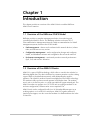
1.1 Overview of the RADview FCAPS Model
RADview provides a complete management solution for monitoring and
controlling the ASMi-52 device. The RADview solutions conform to ITU-T
Telecommunication Management Network (TMN) recommendations for SNMP
management systems, known as the FCAPS model:
•
Fault management – detects and correlates fault in network devices, isolates
faults, and initiates recovery actions
•
Configuration management – tracks configuration changes and configures,
installs, and distributes software and configuration files across the network
•
Performance management – continuously monitors network performance
(QoS, CoS) and resource allocation
1.2 Overview of the ASMi-52 Device
ASMi-52 is a part of SHDSL technology, which offers a cost-effective solution for
delivering digital data. The data is delivered to customer premises over the existing
copper cables of the distribution network, while eliminating the need for
repeaters. The ASMi-52 modem is based on multiple-line rate SHDSL technology.
The modem is fully synchronous and operates in full duplex form. The modem
uses 2-wire or 4-wire line pairs, or a single unconditional copper twisted pair. The
ASMi-52 modem can operate as a CO or CPE unit (according to method of use
and user configuration). Different units are not required. The
ASMi-52 unit can be configured locally via a 10/100 mbps Ethernet port (as an
ordering option) or via an RS-232 control port. ASMi-52, together with an E1
interface port support, can also access the modem via a dedicated time slot in the
E1 interface.
Overview of the ASMi-52 Device
1-1
RADview-EMS ASMi-52 User’s Manual
Chapter 1 Introduction
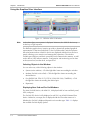
Using the Graphical User Interface
Figure 1-1. RADview ASMi-52 Window
Note
In the above figure, one repeater is displayed. However, the ASMi-52 device may
include up to eight repeaters.
The RADview graphical user interface provides a dynamically updated graphical
representation of the Near End ASMi-52, the Far End modem, and the repeaters
that exist between them. ASMi-52 devices are displayed with their front and rear
panels, allowing you to monitor and manage their operations. The window
includes port interfaces and their operational and communication statuses, as well
as the devices’ LED indicator statuses. Configuration and monitoring can be done
at the system level, modem level, and port level.
Selecting Objects in the Window
You can select any of the following objects in the window:
•
System (entire window) – Click the light blue frame surrounding the window.
•
Modem (Far End or Near End) – Click the light blue frame surrounding the
desired device.
•
Port [SHDSL link, ETH, E1/T1, DTE (V.35/X.21/RS-530), CONTROL] – Click
the light blue frame surrounding the desired port.
•
Repeater(s)
Displaying Near End and Far End Modems
The Near End (NE) device, the ASMi-52, is displayed with its front and back panel,
LEDs, and ports.
The Far End (FE) device is fully displayed as well if it is an ASMi-52/Master/Slave
device. Otherwise, an empty box is displayed with the FE modem name on it.
Whether the Far End is displayed depends on its modem type. Table 1-1 displays
the available Far End display options.
1-2
Overview of the ASMi-52 Device
RADview-EMS ASMi-52 User’s Manual
Chapter 1 Introduction
Table 1-1. Far End Display Options
FE Modem
Modem Type
Managed/Unmanaged
Unknown
Unknown
Unmanaged
ASMi-52
ASMi-52 SA
Managed
ASMi-52 Master
ASMi-52 SA
Managed
ASMi-52 Slave
ASMi-52 SA
Managed
ASMi-52/CD
LRS-24 Card
Managed
ASMi-52/CQ
LRS-24 Card
Managed
LRS-52
LRS-52
Managed
D8SL
DXC Card
Managed
MP-SHDSL
MP Card
Managed
FCD-IP
FCD-IP
Unmanaged
FCD-IPM
FCD-IPM
Unmanaged
Menu Bar
The menu bar includes the following pull-down menus: Configuration, Fault,
Diagnostics, Options, and Help. Menu availability and content varies depending
on the selected object (system, modem, or port).
Toolbar
The following buttons are available on the toolbar:
System Info – Displays the system information for the selected interface
Poll Agent – Polls the Agent immediately
Status Bar
The status bar indicates if RADview ASMi-52 is ready, if there is a system error, or
if the Agent is currently being polled.
LEDs
Note
LED status is displayed only for ASMi-52 and ASMi-52 Master/Slave devices.
The front panel of ASMi-52 includes a series of LED indicators that show the
current operating status. Table 1-2 lists and describes the ASMi-52 LED indicators.
Table 1-2. ASMi-52 LEDs
Name
Function
Location
PWR (green)
ON – Power supply is ON
Front panel
OFF – Power supply is OFF
TST (red)
ON – Test is active on one of the device’s ports
Front panel
OFF – No test is active on any of the device’s ports
Overview of the ASMi-52 Device
1-3
RADview-EMS ASMi-52 User’s Manual
Chapter 1 Introduction
Table 1-2. ASMi-52 LEDs (Cont.)
Name
Function
Location
SYNC
(green/red)
or
SYNC A
(green/red)
The SYNC LED is for 2W modems
Front panel
The SYNC A LED is for 4W modems
• ON (red) – Snyc Line A operation state is IDLE,
BOOTUP_LOAD, or BOOTUP_LOAD_DONE
• Blinking (red) – Snyc Line A operation state is
HANDSHAKE_OP
• Blinking (green) – TRAINING_OP and FRAMER_SYNC
• ON (green) – Snyc Line A operation state is DATA
SYNC B
(green/red)
The SYNC B LED is only applicable for 4W modems
Front panel
• ON (red) – Snyc Line B operation state is IDLE,
BOOTUP_LOAD, or BOOTUP_LOAD_DONE
• Blinking (red) – Snyc Line B operation state is
HANDSHAKE_OP
• Blinking (green) – TRAINING_OP and FRAMER_SYNC
• ON (green) – Snyc Line B operation state is DATA
AIS (yellow)
or
YELLOW
(yellow)
The AIS LED is applicable only for the E1 interface
Front panel
• ON – AIS received
• OFF – No AIS received
The YELLOW LED is applicable only for the T1 interface
• ON – Yellow alarm
• OFF – No Yellow alarm
E1 SYNC /
T1 SYNC (red)
or
DATA (yellow)
The E1 SYNC / T1 SYNC LED is only applicable for an E1/T1
interface
Front panel
• ON (red) – E1/T1 is not synchronized
• OFF – E1/T1 is synchronized
The DATA LED is not applicable for an E1/T1 interface
Blinking (yellow) – Data is being received or transmitted via the
DTE interface
OFF – No data
ALM (red)
ON (red) – An alarm exists
OFF – No data
1-4
Overview of the ASMi-52 Device
Front panel
RADview-EMS ASMi-52 User’s Manual
Chapter 1 Introduction
Port Status
The operational status of each physical port is indicated by the color of the port.
The color displayed is based both on polling and on notifications of interface
operational status.
The color appears according to the following order of conditions:
Table 1-3. ASMi-52 Port Statuses
Name
Function
Location
Magenta
There are failures on the port
Front panel
Light Blue
There is an active test on the port
Front panel
Gray
The port is operational, and no test is running
Front panel
1.3 System Level Operations
Table 1-4 lists the different management options for the system level.
Table 1-4. System Management Options
Tasks – Fault
Dialog Box and/or Parameter
Location
Path
Masking the alarms
Refer to Masking the Alarms in
Chapter 2.
Fault
´Mask Alarms…
Clearing the history
log
Refer to Clearing the History Log in
Chapter 2.
Fault
´History Log
´Clear All
Tasks –
Configuration
Dialog Box and/or Parameter
Location
Path
Configuring system
information
System Information Dialog Box
Configuration
´System Info…
Polling the Agent
Refer to Polling the Agent in
Chapter 3.
Configuration
´Poll Agent
Viewing the host
interface list
Host Interface List Dialog Box
Options
´Host Interface List…
Refer to Viewing and Setting
System Information in Chapter 3.
Refer to Viewing the Host Interface
List Chapter 3.
Configuring the
manager list
Manager List Dialog Box
Setting the polling
option
Refer to Setting the Polling Option
in Chapter 3.
Refer to Configuring the Manager
List in Chapter 3.
Options
´Manager List…
Options
´Polling
System Level Operations
1-5
RADview-EMS ASMi-52 User’s Manual
Chapter 1 Introduction
Table 1-4. System Management Options (Cont.)
Task – Statistics
Dialog Box and/or Parameter
Location
Path
Setting the polling
interval
Polling Interval Dialog Box
Statistics
´Polling Interval…
Refer to Setting the Polling Interval
in Chapter 4.
1.4 Modem Level Operations
Table 1-5 lists the different management options for the modem level.
Table 1-5. Modem Management Options
1-6
Tasks – Fault
Dialog Box and/or Parameter
Location
Path
Displaying the
active alarms for
modems and ports
All Modem Active Alarm List Dialog
Box
Fault
´Active Alarms
´Modem & Ports…
Displaying the
active alarms at the
modem level
Modem Active Alarm List Dialog
Box
Displaying the
history log for the
active alarms at the
modem level
Modem Alarm Buffer List Dialog
Box
Tasks –
Configuration
Dialog Box and/or Parameter
Location
Path
Viewing modem
information
Modem Information Dialog Box
Configuration
´Modem Info…
Configuring the
modem
parameters
Modem Parameters Dialog Box
Viewing available
bandwidth
Bandwidth Allocation Dialog Box
Modem Level Operations
Refer to Displaying the Active
Alarms for Modems and Ports in
Chapter 2.
Refer to Displaying the Active
Alarms at the Modem Level in
Chapter 2.
Refer to Displaying the History Log
in Chapter 2.
Refer to Viewing Modem
Information in Chapter 3.
Refer to Configuring the Modem
Parameters in Chapter 3.
Refer to Viewing Available
Bandwidth in Chapter 3.
Fault
´Active Alarms
´Modem Level…
Fault
´History Log
´List…
Configuration
´Modem Parameters…
Configuration
´Bandwidth Allocation…
RADview-EMS ASMi-52 User’s Manual
Chapter 1 Introduction
Table 1-5. Modem Management Options (Cont.)
Tasks –
Configuration
Dialog Box and/or Parameter
Location
Path
Configuring the
LAN
LAN Configuration Dialog Box
Configuration
´LAN Configuration…
Configuring the
bridging table
Bridging Table Dialog Box
Configuring QoS
mapping
QoS Mapping Dialog Box
Refer to Configuring the LAN in
Chapter 3.
Configuration
´Bridging Table…
Refer to Configuring the Bridging
Table in Chapter 3.
Refer to Configuring QoS Mapping
in Chapter 3.
Configuration
´QoS Mapping…
Resetting the
modem hardware
Refer to Resetting the Modem
Hardware in Chapter 3.
Configuration
´Reset
´Modem HW
Resetting the
modem
configuration
Refer to Resetting the Modem
Configuration in Chapter 3.
Configuration
´Reset
´Configuration
Resetting the Line
Configuration
Refer to Resetting the Line
Configuration in Chapter 3.
Configuration
´Reset
´Line
Testing the modem
diagnostics
Test Dialog Box
Diagnostics
´Test…
Configuring BERT
testing
BERT Counters Dialog Box
Refer to Testing the Modem
Diagnostics in Chapter 3.
Refer to Configuring BERT Testing in
Chapter 3.
Diagnostics
´BERT Counters…
Task – Statistics
Dialog Box and/or Parameter
Location
Path
Clearing modem
statistics
Refer to Clearing Modem Statistics
in Chapter 4.
Statistics
´Clear Modem Statistics…
Modem Level Operations
1-7
RADview-EMS ASMi-52 User’s Manual
Chapter 1 Introduction
1.5 SHDSL Link Port Level Operations
Table 1-6 lists the different management options for the SHDSL Link port level.
Table 1-6. SHDSL Link Port Management Options
1-8
Task – Fault
Dialog Box and/or Parameter
Location
Path
Displaying the
active alarms at the
SHDSL Link port
level
Port Active Alarm List Dialog Box
Fault
´Active Alarms…
Tasks –
Configuration
Dialog Box and/or Parameter
Location
Path
Configuring the
SHDSL Link port
parameters
Port Parameters Dialog Box
Configuration
´Parameters…
Viewing the
SHDSL Link port
status configuration
Port Status Dialog Box
Tasks – Statistics
Dialog Box and/or Parameter
Location
Path
Viewing port data
from the beginning
of the current 15minute interval
15 min Current Data Dialog Box
Statistics
´Line
´15 min Current Data…
Viewing port data
from the beginning
of the current
one-day interval
One Day Current Data Dialog Box
Viewing port data
for all 15-minute
intervals over the
last 24 hours
15 min Interval Data Dialog Box
Viewing port data
at one-day
intervals
One Day Interval Data Dialog Box
Viewing
accumulated data
for the SHDSL link
port
Accumulated Data Dialog Box
Refer to Displaying the Active
Alarms at the SHDSL Link Port Level
in Chapter 2.
Refer to Configuring the SHDSL
Link Port Parameters in Chapter 3.
Refer to Viewing the SHDSL Link
Port Status Configuration in
Chapter 3.
Refer to Viewing Current 15-Minute
Data for the SHDSL Link Port in
Chapter 4.
Refer to Viewing One-Day Current
Data for the SHDSL Link Port in
Chapter 4.
Refer to Viewing 15-Minute Interval
Data for the SHDSL Link Port in
Chapter 4.
Refer to Viewing One-Day Interval
Data for the SHDSL Link Port in
Chapter 4.
Refer to Viewing Accumulated Data
for the SHDSL Link Port in
Chapter 4.
SHDSL Link Port Level Operations
Configuration
´Status…
Statistics
´Line
´One Day Current Data...
Statistics
´Line
´15 min Interval Data
Statistics
´Line
´One Day Interval Data…
Statistics
´Line
´Accumulated Data…
RADview-EMS ASMi-52 User’s Manual
Chapter 1 Introduction
Table 1-6. SHDSL Link Port Management Options (Cont.)
Task – Statistics
Dialog Box and/or Parameter
Location
Path
Clearing port
statistics at the
SHDSL Link port
level
Refer to Clearing Statistics for the
SHDSL Link Port in Chapter 4.
Statistics
´Clear Statistics…
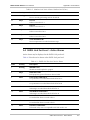
1.6 ETH Port Level Operations
Table 1-7 lists the different management options for the ETH port level.
Table 1-7. ETH Port Management Options
Task – Fault
Dialog Box and/or Parameter
Location
Path
Displaying the
active alarms at the
ETH port level
Port Active Alarm List Dialog Box
Fault
´Active Alarms…
Task –
Configuration
Dialog Box and/or Parameter
Location
Path
Configuring the
ETH port
parameters
Port Parameters Dialog Box
Configuration
´Parameters…
Refer to Displaying the Active
Alarms at the ETH Port Level in
Chapter 2.
Refer to Configuring the ETH Port
Parameters in Chapter 3.
1.7 E1 and T1 Port Level Operations
Table 1-8 lists the different management options for the E1 and T1 port levels.
Table 1-8. E1 and T1 Port Management Options
Task – Fault
Dialog Box and/or Parameter
Location
Path
Displaying the
active alarms at the
E1 port level
Port Active Alarm List Dialog Box
Fault
´Active Alarms…
Refer to Displaying the Active
Alarms at the E1 Port Level in
Chapter 2.
E1 and T1 Port Level Operations
1-9
RADview-EMS ASMi-52 User’s Manual
Chapter 1 Introduction
Table 1-8. E1 and T1 Port Management Options (Cont.)
Tasks –
Configuration
Dialog Box and/or Parameter
Location
Path
Configuring the
parameters for the
E1 port
Port Parameters Dialog Box
Configuration
´Parameters…
Configuring the
parameters for the
T1 port
Refer to Configuring the Parameters
for the T1 Port in Chapter 3.
Configuration
´Parameters…
Tasks – Statistics
Dialog Box and/or Parameter
Location
Path
Viewing BPV
statistics
BPV Statistics Dialog Box
Statistics
´BPV…
Viewing current
15-minute port
data
15 min Current Data Dialog Box
Viewing 15-minute
interval port data
15 min Interval Data Dialog Box
Clearing statistics
for the E1/T1 port
Refer to Clearing Statistics for the
E1/T1 Port in Chapter 4.
Refer to Configuring the Parameters
for the E1 Port in Chapter 3.
Refer to Viewing BPV Statistics in
Chapter 4.
Refer to Viewing Current 15-Minute
Port Data in Chapter 4.
Refer to Viewing 15-Minute Interval
Port Data in Chapter 4.
Statistics
´15 min Current Data…
Statistics
´15 min Interval Data...
Statistics
´Clear Statistics…
1.8 DTE (V.35, X.21, RS-530) Port Levels Operations
Table 1-9 lists the different management options for the DTE (V.35, X.21, RS-530)
port levels.
Table 1-9. DTE (V.35, X.21, RS-530) Port Management Options
1-10
Task – Fault
Dialog Box and/or Parameter
Location
Path
Displaying the
active alarms at the
DTE (V.35, X.21,
RS-530) port levels
Port Active Alarm List Dialog Box
Fault
´Active Alarms…
Task –
Configuration
Dialog Box and/or Parameter
Location
Path
Configuring the
DTE (V.35,
RS-530) port
parameters
Port Parameters Dialog Box
Configuration
´Parameters…
Refer to Displaying the Active Alarms
at the DTE (V.35, X.21, RS-530, IR-IP)
Port Levels in Chapter 2.
Refer to Configuring the DTE (V.35,
RS-530) Port Parameters in
Chapter 3.
DTE (V.35, X.21, RS-530) Port Levels Operations
RADview-EMS ASMi-52 User’s Manual
Chapter 1 Introduction
1.9 CONTROL Port Level Operations
Table 1-10 lists the different management options for the CONTROL port level.
Table 1-10. CONTROL Port Management Options
Task –
Configuration
Dialog Box and/or Parameter
Location
Path
Configuring the
CONTROL port
parameters
Port Parameters Dialog Box
Configuration
´Parameters…
1.10
Refer to Configuring the CONTROL
Port Parameters in Chapter 3.
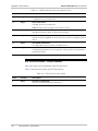
Repeater Level Operations
Table 1-11 lists the different management options for the repeater level.
Table 1-11. Repeater Management Options
Tasks – Fault
Dialog Box and/or Parameter
Location
Path
Displaying the
active alarms at the
repeater level
Repeater Active Alarm List Dialog
Box
Fault
´Active Alarms…
Displaying the
history log
Repeater Alarm Buffer List Dialog
Box
Refer to Displaying the Active
Alarms at the Repeater Level in
Chapter 2.
Refer to Displaying the History Log
in Chapter 2.
Fault
´History Log
´List…
Tasks –
Configuration
Dialog Box and/or Parameter
Location
Path
Configuring the
repeater
parameters
Repeater Parameters Dialog Box
Configuration
´Parameters…
Resetting the
repeater network
side
Refer to Resetting the Repeater
Network Side in Chapter 2.
Configuration
´Reset Network Side
Tasks –
Diagnostics
Dialog Box and/or Parameter
Location
Path
Testing the
repeater
diagnostics
Repeater Test Dialog Box
Diagnostics
´Test…
Refer to Configuring the Repeater
Parameters in Chapter 2.
Refer to Testing the Repeater
Diagnostics in Chapter 2.
Repeater Level Operations
1-11
Chapter 1 Introduction
1-12
Repeater Level Operations
RADview-EMS ASMi-52 User’s Manual
Chapter 2
Fault Management
This chapter describes ASMi-52 fault management at the system, modem, port,
and repeater levels.
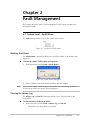
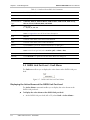
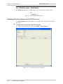
2.1 System Level – Fault Menu
The Fault menu provides access to the system alarm options.
Figure 2-1. System Level Fault Menu
Masking the Alarms
The Mask Alarms command enables you to mask the alarms of all modems and
repeaters.
To mask the alarms of all modems and repeaters:
1. At the system level, select Fault > Mask Alarms...
Figure 2-2. Mask Alarms Dialog Box
2. Select or deselect the Mask Alarms checkbox and click <Set>.
Note
If you mask an alarm, it will not appear in the alarm list or history log. In addition,
no alarm trap will be sent for the corresponding port.
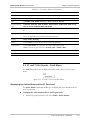
Clearing the History Log
The History Log > Clear All command enables you to clear all entries in the
alarm buffer.
To clear all entries in the alarm buffer:
•
At the system level, select Fault > History Log > Clear All.
All entries in the alarm buffer are cleared.
System Level – Fault Menu
2-1
RADview-EMS ASMi-52 User’s Manual
Chapter 2 Fault Management
2.2 Modem Level – Fault Menu
The Fault menu allows you to display the active alarms at the modem level. You
can view the active alarms for modems and ports, or for modems only.
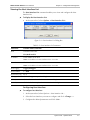
Figure 2-3. Modem Level Fault Menu
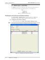
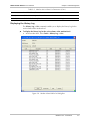
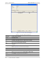
Displaying the Active Alarms for Modems and Ports
The Active Alarms > Modems & Ports command enables you to display the
active alarms of the selected modem at both the modem and port levels.
To display the active alarms at all levels:
•
Note
At the modem level, select Fault > Active Alarms > Modems & Ports…
You can sort the Active Alarm List by clicking any of the column headings.
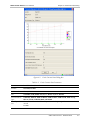
Figure 2-4. All Modem Active Alarm List Dialog Box
2-2
Modem Level – Fault Menu
RADview-EMS ASMi-52 User’s Manual
Chapter 2 Fault Management
Table 2-1. All Modem Active Alarm List Parameters
Parameter
Possible Values / Remarks
Location
Near-End, Far-End
SHDSL Mode
STU-C, STU-R
Far-End Modem
Type
Unknown, ASMi-52, ASMi-52 Master, ASMi-52 Slave, ASMi-52/CD, ASMi-52/CQ,
LRS-52, FCD-IP, FCD-IPM, D8SL, MP-SHDSL
Port
The port reporting the alarm
Code
Alarm code
1…43, 50, 51, 60…66
Description
Description of the alarm
Note: See Appendix A for a full list of alarm descriptions
Severity
Major, Minor, Warning
[Close]
Click <Close> to close the All Modem Active Alarm List dialog box
[Save to File...]
Click <Save to File...> to save the All Modem Active Alarm List to a file
Note: In the File of type field, select Acrobat (*pdf) or HTML (*.htm)
[Print...]
Click <Print...> to print the All Modem Active Alarm List
[Refresh]
Click <Refresh> to update the All Modem Active Alarm List dialog box
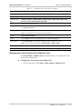
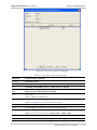
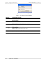
Displaying the Active Alarms at the Modem Level
The Active Alarms > Modem Level command enables you to display the active
alarms at the modem level.
To display the active alarms at the modem level:
•
At the modem level, select Fault > Active Alarms > Modem Level…
Modem Level – Fault Menu
2-3
RADview-EMS ASMi-52 User’s Manual
Chapter 2 Fault Management
Figure 2-5. Modem Active Alarm List Dialog Box
Table 2-2. Modem Active Alarm List Parameters
Parameter
Possible Values / Remarks
Location
Near-End, Far-End
SHDSL Mode
STU-C, STU-R
Far-End Modem
Type
Unknown, ASMi-52, ASMi-52 Master, ASMi-52 Slave, ASMi-52/CD, ASMi-52/CQ,
LRS-52, FCD-IP, FCD-IPM, D8SL, MP-SHDSL
Code
Alarm code
1, 2, 20, 23, 42, 43, 51, 60…66
Description
Description of the alarm
Note: See Appendix A for a full list of alarm descriptions
Severity
Major, Minor, Warning
[Close]
Click <Close> to close the Modem Active Alarm List dialog box
[Save to File...]
Click <Save to File...> to save the Modem Active Alarm List to a file
Note: In the File of type field, select Acrobat (*pdf) or HTML (*.htm)
2-4
Modem Level – Fault Menu
RADview-EMS ASMi-52 User’s Manual
Chapter 2 Fault Management
Table 2-2. Modem Active Alarm List Parameters (Cont.)
Parameter
Possible Values / Remarks
[Print...]
Click <Print...> to print the Modem Active Alarm List
[Refresh]
Click <Refresh> to update the Modem Active Alarm List dialog box
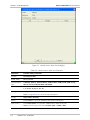
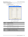
Displaying the History Log
The History Log > List command enables you to display the history log for the
active alarms at the modem level.
To display the history log for the active alarms at the modem level:
•
At the modem level, select Fault > History Log > List…
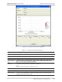
Figure 2-6. Modem Alarm Buffer List Dialog Box
Modem Level – Fault Menu
2-5
RADview-EMS ASMi-52 User’s Manual
Chapter 2 Fault Management
Table 2-3. Modem Alarm Buffer List Parameters
Parameter
Possible Values / Remarks
Location
Near-End, Far-End
SHDSL Mode
STU-C, STU-R
Far-End Modem
Type
Unknown, ASMi-52, ASMi-52 Master, ASMi-52 Slave, ASMi-52/CD, ASMi-52/CQ,
LRS-52, FCD-IP, FCD-IPM, D8SL, MP-SHDSL
Code
Alarm code
1…43, 50, 51, 60…66
Description
Description of the alarm
Note: See Appendix A for a full list of alarm descriptions
State
Off, On
Date
The date of the alarm, in the format YYYY-MM-DD
Time
The time of the alarm, in the format HH:MM:SS
[Close]
Click <Close> to close the Modem Alarm Buffer List dialog box
[Save to File...]
Click <Save to File...> to save the Modem Alarm Buffer List to a file
Note: In the File of type field, select Acrobat (*pdf) or HTML (*.htm)
[Print...]
Click <Print...> to print the Modem Alarm Buffer List
[Refresh]
Click <Refresh> to update the Modem Alarm Buffer List dialog box
2.3 SHDSL Link Port Level – Fault Menu
The Fault menu allows you to display the active alarms at the SHDSL Link port
level.
Figure 2-7. SHDSL Link Port Level Fault Menu
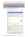
Displaying the Active Alarms at the SHDSL Link Port Level
The Active Alarms command enables you to display the active alarms at the
SHDSL Link port level.
To display the active alarms at the SHDSL Link port level:
•
2-6
At the SHDSL Link port level (NE or FE), select Fault > Active Alarms...
SHDSL Link Port Level – Fault Menu
RADview-EMS ASMi-52 User’s Manual
Chapter 2 Fault Management
Figure 2-8. Port Active Alarm List Dialog Box
Table 2-4. Port Active Alarm List Parameters
Parameter
Possible Values / Remarks
Location
Near-End, Far-End
SHDSL Mode
STU-C, STU-R
Port
CONTROL, ETH, SHDSL Link, E1, T1, DTE (V.35, X.21, RS-530)
Far-End Modem
Type
Unknown, ASMi-52, ASMi-52 Master, ASMi-52 Slave, ASMi-52/CD, ASMi-52/CQ,
LRS-52, FCD-IP, FCD-IPM, D8SL, MP-SHDSL
Code
Alarm code
3, 6, 9…14, 16…19, 21, 22, 50
Description
Description of the alarm
Note: See Appendix A for a full list of alarm descriptions
Severity
Major, Minor, Warning
[Close]
Click <Close> to close the Port Active Alarm List dialog box
[Save to File...]
Click <Save to File...> to save the Port Active Alarm List to a file
Note: In the File of type field, select Acrobat (*pdf) or HTML (*.htm)
[Print...]
Click <Print...> to print the Port Active Alarm List
[Refresh]
Click <Refresh> to update the Port Active Alarm List dialog box
SHDSL Link Port Level – Fault Menu
2-7
RADview-EMS ASMi-52 User’s Manual
Chapter 2 Fault Management
2.4 ETH Port Level – Fault Menu
The Fault menu allows you to display the active alarms at the ETH port level.
Figure 2-9. ETH Port Level Fault Menu
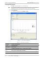
Displaying the Active Alarms at the ETH Port Level
The Active Alarms command enables you to display the active alarms at the ETH
port level.
To display the active alarms at the ETH port level:
•
At the ETH port level (NE or FE), select Fault > Active Alarms...
Figure 2-10. Port Active Alarm List Dialog Box
2-8
ETH Port Level – Fault Menu
RADview-EMS ASMi-52 User’s Manual
Chapter 2 Fault Management
Table 2-5. Port Active Alarm List Parameters
Parameter
Possible Values / Remarks
Location
Near-End, Far-End
SHDSL Mode
STU-C, STU-R
Port
CONTROL, ETH, SHDSL Link, E1, T1, DTE (V.35, X.21, RS-530)
Far-End Modem
Type
Unknown, ASMi-52A, ASMi-52 Master, ASMi-52 Slave, ASMi-52/CD, ASMi-52/CQ,
LRS-52, FCD-IP, FCD-IPM, D8SL, MP-SHDSL
Code
Alarm code
8
Description
Description of the alarm
Note: See Appendix A for a full list of alarm descriptions
Severity
Major, Minor, Warning
[Close]
Click <Close> to close the Port Active Alarm List dialog box
[Save to File...]
Click <Save to File...> to save the Port Active Alarm List to a file
Note: In the File of type field, select Acrobat (*pdf) or HTML (*.htm)
[Print...]
Click <Print...> to print the Port Active Alarm List
[Refresh]
Click <Refresh> to update the Port Active Alarm List dialog box
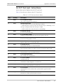
2.5 E1 and T1 Port Levels – Fault Menu
The Fault menu allows you to display the active alarms at the E1 and T1 port
levels.
Figure 2-11. E1 and T1 Port Level Fault Menu
Displaying the Active Alarms at the E1 Port Level
The Active Alarms command enables you to display the active alarms at the E1
and T1 port levels.
To display the active alarms at the E1 and T1 port levels:
•
At the E1/T1 port level (NE or FE), select Fault > Active Alarms...
E1 and T1 Port Levels – Fault Menu
2-9
RADview-EMS ASMi-52 User’s Manual
Chapter 2 Fault Management
Figure 2-12. Port Active Alarm List Dialog Box
Table 2-6. Port Active Alarm List Parameters
Parameter
Possible Values / Remarks
Location
Near-End, Far-End
SHDSL Mode
STU-C, STU-R
Port
CONTROL, ETH, SHDSL Link, E1, T1, DTE (V.35, X.21, RS-530)
Far-End Modem
Type
Unknown, ASMi-52, ASMi-52 Master, ASMi-52 Slave, ASMi-52/CD, ASMi-52/CQ,
LRS-52, FCD-IP, FCD-IPM, D8SL, MP-SHDSL
Code
Alarm code
7, 24…41
Description
Description of the alarm
Note: See Appendix A for a full list of alarm descriptions
Severity
Major, Minor, Warning
[Close]
Click <Close> to close the Port Active Alarm List dialog box
[Save to File...]
Click <Save to File...> to save the Port Active Alarm List to a file
Note: In the File of type field, select Acrobat (*pdf) or HTML (*.htm)
[Print...]
Click <Print...> to print the Port Active Alarm List
[Refresh]
Click <Refresh> to update the Port Active Alarm List dialog box
2-10
E1 and T1 Port Levels – Fault Menu
RADview-EMS ASMi-52 User’s Manual
Chapter 2 Fault Management
2.6 DTE (V.35, X.21, RS-530, IR-IP) Port Levels – Fault
Menu
The Fault menu allows you to display the active alarms at the DTE (V.35, X.21, RS530, IR-IP) port levels.
Figure 2-13. DTE (V.35, X.21, RS-530, IR-IP) Port Level Fault Menu
Displaying the Active Alarms at the DTE (V.35, X.21, RS-530, IR-IP) Port
Levels
The Active Alarms command enables you to display the active alarms at the DTE
(V.35, X.21, RS-530, IR-IP) port levels.
To display the active alarms at the DTE (V.35, X.21, RS-530, IR-IP) port levels:
•
At the DTE (V.35, X.21, RS-530, IR-IP) port level, select Fault > Active
Alarms...
Figure 2-14. Port Active Alarm List Dialog Box
DTE (V.35, X.21, RS-530, IR-IP) Port Levels – Fault Menu
2-11
RADview-EMS ASMi-52 User’s Manual
Chapter 2 Fault Management
Table 2-7. Port Active Alarm List Parameters
Parameter
Possible Values / Remarks
Location
Near-End, Far-End
SHDSL Mode
STU-C, STU-R
Port
CONTROL, ETH, SHDSL Link, E1, T1, DTE (V.35, X.21, RS-530)
Far-End Modem
Type
Unknown, ASMi-52, ASMi-52 Master, ASMi-52 Slave, ASMi-52/CD, ASMi-52/CQ,
LRS-52, FCD-IP, FCD-IPM, D8SL, MP-SHDSL
Code
Alarm code
4, 5, 8, 15, 51
Note: Bits 4 and 5 are only relevant for V.35/RS-530
Note: Bit 8 is only relevant for IR-IP
Description
Description of the alarm
Note: See Appendix A for a full list of alarm descriptions
Severity
Major, Minor, Warning
[Close]
Click <Close> to close the Active Alarm List dialog box
[Save to File...]
Click <Save to File...> to save the Port Active Alarm List to a file
Note: In the File of type field, select Acrobat (*pdf) or HTML (*.htm).
[Print...]
Click <Print...> to print the Port Active Alarm List
[Refresh]
Click <Refresh> to update the Port Active Alarm List
2.7 Repeater Level – Fault Menu
The Fault menu allows you to display active alarms at the repeater level.
Figure 2-15. Repeater Level Fault Menu
Displaying the Active Alarms at the Repeater Level
The Active Alarms command enables you to display the active alarms at the
repeater level.
To display the active alarms at the repeater level:
1. In the RADview ASMi-52 window, select a repeater.
2. Select Fault > Active Alarms…
Note
2-12
You can sort the Active Alarm List by clicking any of the column headings.
Repeater Level – Fault Menu
RADview-EMS ASMi-52 User’s Manual
Chapter 2 Fault Management
Figure 2-16. Repeater Active Alarm List Dialog Box
Table 2-8. Repeater Active Alarm List Parameters
Parameter
Possible Values / Remarks
Repeater
1…8
Code
Alarm code
44…49
Description
Description of the alarm
Note: See Appendix A for a full list of alarm descriptions
Severity
Major, Minor, Warning
[Close]
Click <Close> to close the Repeater Active Alarm List dialog box
[Save to File...]
Click <Save to File...> to save the Repeater Active Alarm List to a file
Note: In the File of type field, select Acrobat (*pdf) or HTML (*.htm)
[Print...]
Click <Print...> to print the Repeater Active Alarm List
[Refresh]
Click <Refresh> to update the Repeater Active Alarm List dialog box
Repeater Level – Fault Menu
2-13
RADview-EMS ASMi-52 User’s Manual
Chapter 2 Fault Management
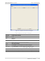
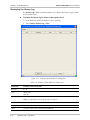
Displaying the History Log
The History Log > List command enables you to display the history log for alarms
at the repeater level.
To display the history log for alarms at the repeater level:
1. In the RADview ASMi-52 window, select a repeater.
2. Select Fault > History Log > List…
Figure 2-17. Repeater Alarm Buffer List Dialog Box
Table 2-9. Repeater Alarm Buffer List Parameters
Parameter
Possible Values / Remarks
Repeater
1…8
Code
Alarm code
44…49
Description
Description of the alarm
Note: See Appendix A for a full list of alarm descriptions
State
On, Off
Date
The date of the alarm, in the format YYYY-MM-DD
Time
The time of the event, in the format HH:MM:SS
2-14
Repeater Level – Fault Menu
RADview-EMS ASMi-52 User’s Manual
Chapter 2 Fault Management
Table 2-9. Repeater Alarm Buffer List Parameters (Cont.)
Parameter
Possible Values / Remarks
[Close]
Click <Close> to close the Repeater Alarm Buffer List dialog box
[Save to File...]
Click <Save to File...> to save the Repeater Alarm Buffer List to a file
Note: In the File of type field, select Acrobat (*pdf) or HTML (*.htm)
[Print...]
Click <Print...> to print the Repeater Alarm Buffer List
[Refresh]
Click <Refresh> to update the Repeater Alarm Buffer List dialog box
Repeater Level – Fault Menu
2-15
Chapter 2 Fault Management
2-16
Repeater Level – Fault Menu
RADview-EMS ASMi-52 User’s Manual
Chapter 3
Configuration Management
The chapter describes the ASMi-52 configuration management at the system,
modem, port, and repeater levels.
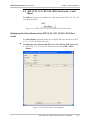
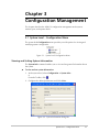
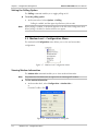
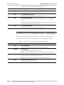
3.1 System Level – Configuration Menu
The system level Configuration menu provides you with options for viewing and
modifying system configuration.
Figure 3-1. System Level Configuration Menu
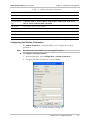
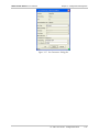
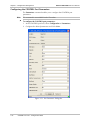
Viewing and Setting System Information
The System Info command enables you to view and set general information about
the system.
To view and set system information:
1. At the system level, select Configuration > System Info...
or
From the Toolbar, click .
2. Configure the desired parameters and click <Set>.
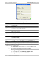
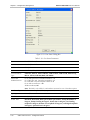
Figure 3-2. System Information Dialog Box
System Level – Configuration Menu
3-1
RADview-EMS ASMi-52 User’s Manual
Chapter 3 Configuration Management
Table 3-1. System Information Parameters
Parameter
Possible Values / Remarks
Description
Description of the device, including hardware and software versions
Object ID
Device’s SNMP Object ID
Name
Name of the device, a string of up to 12 characters
Contact
Name of the person responsible for the functioning of this device, a string of up to
32 characters
Location
Exact location of this device, a string of up to 32 characters
System Up Time
Amount of time that elapsed since this device was reset, in the format X days HH:MM:SS
Number of
Interfaces
Number of physical and logical interfaces on this device
[Set]
Click <Set> to set the system information configuration parameters
[Cancel]
Click <Cancel> to close the System Information dialog box
[Refresh]
Click <Refresh> to update the System Information dialog box
Polling the Agent
The Poll Agent command enables you to poll the Agent immediately.
To poll the Agent:
•
At the system level, select Configuration > Poll Agent.
or
From the Toolbar, click .
The system immediately polls the Agent and updates the displayed
information.
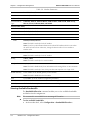
3.2 System Level – Options Menu
The Options menu allows you to view and configure the Host Interface List, the
Manager List, and enable the polling option.
Figure 3-3. System Level Options Menu
3-2
System Level – Options Menu
RADview-EMS ASMi-52 User’s Manual
Chapter 3 Configuration Management
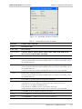
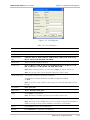
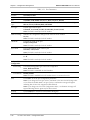
Viewing the Host Interface List
The Host Interface List command enables you to view and configure the Host
Interface List.
To display the Host Interface List:
•
At the system level, select Options > Host Interface List…
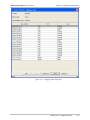
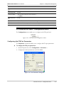
Figure 3-4. Host Interface List Dialog Box
Table 3-2. Host Interface List Parameters
Parameter
Possible Values / Remarks
Host
The name of the Host
ETH, Dedicated TS
IP Address
The IP address of the Host
Note: An IP address of 0.0.0.0 indicates there is no Host
IP Mask
The IP Mask of the Host
Note: An IP address of 0.0.0.0 indicates there is no Host
Host Tagging
Tagged, Untagged
Host VLAN ID
1…4094
Host Priority Tag
0…7
[Change]
Click <Change> to open the dialog box
[Close]
Click <Close> to close the Host Interface List dialog box
[Refresh]
Click <Refresh> to update the Host Interface List dialog box
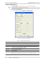
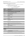
Configuring Host Interface
To configure host interface:
1. At the system level, select Options > Host Interface List…
2. Select the host interface you want to configure and click <Change…>.
3. Configure the desired parameters and click <Set>.
System Level – Options Menu
3-3
Chapter 3 Configuration Management
RADview-EMS ASMi-52 User’s Manual
Figure 3-5. Host Interface Change Dialog Box
Table 3-3. Host Interface Change Parameters
Parameter
Possible Values / Remarks
Host
The name of the Host
ETH, Dedicated TS
IP Address
The IP address of the Host
Note: An IP address of 0.0.0.0 indicates there is no Host
IP Mask
The IP Mask of the Host
Note: An IP address of 0.0.0.0 indicates there is no Host
Host Tagging
Tagged, Untagged
Note: This field only exists if the Host type is ETH
[Set]
Click <Set> to set the configured parameters
[Cancel]
Click <Cancel> to close the Host Interface Change dialog box
3-4
System Level – Options Menu
RADview-EMS ASMi-52 User’s Manual
Chapter 3 Configuration Management
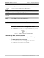
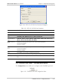
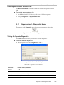
Configuring the Manager List
The Manager List command enables you to configure the Manager List.
To display the Manager List:
•
At the system level, select Options > Manager List…
Figure 3-6. Manager List Dialog Box
Table 3-4. Manager List Parameters
Parameter
Possible Values / Remarks
Manager Id
The number of the Manager Id
1…10
IP Address
The IP address of the Manager
Note: An IP address of 0.0.0.0 indicates there is no Manager
IP Mask
The IP Mask of the Manager
Note: An IP address of 0.0.0.0 indicates there is no Manager
[Set]
Click <Set> to set the Manager List parameters
[Cancel]
Click <Cancel> to close the Manager List dialog box
[Refresh]
Click <Refresh> to update the Manager List dialog box
System Level – Options Menu
3-5
RADview-EMS ASMi-52 User’s Manual
Chapter 3 Configuration Management
Setting the Polling Option
The Polling command enables you to toggle polling on/off.
To set the polling option:
•
At the system level, select Options > Polling.
Polling is enabled, and the Agent is polled every 60 seconds.
Note
When polling is enabled, a checkmark appears to the left of the Polling menu item.
When polling is disabled, a checkmark does not appear.
3.3 Modem Level – Configuration Menu
The modem level Configuration menu allows you to view and set modem
configuration.
Figure 3-7. Modem Level Configuration Menu
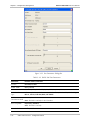
Viewing Modem Information
The Modem Info command enables you to view modem information.
Note
The parameters listed below do not appear for an unmanaged FE modem.
To view modem information:
•
At the modem level, select Configuration > Modem Info…
or
From the Toolbar, click .
Figure 3-8. Modem Information Dialog Box
3-6
Modem Level – Configuration Menu
RADview-EMS ASMi-52 User’s Manual
Chapter 3 Configuration Management
Table 3-5. Modem Information Parameters
Parameter
Possible Values / Remarks
Location
Near-End, Far-End
SHDSL Mode
STU-C, STU-R
Far-End Modem
Type
Unknown, ASMi-52, ASMi-52 Master, ASMi-52 Slave, ASMi-52/CD, ASMi-52/CQ,
LRS-52, FCD-IP, FCD-IPM, D8SL, MP-SHDSL
SW Version
The software version of the modem
HW Version
The hardware version of the modem
IP Address
The IP address of the modem
[Close]
Click <Close> to close the Modem Information dialog box
[Refresh]
Click <Refresh> to update the data in the Modem Information dialog box
Configuring the Modem Parameters
The Modem Parameters command enables you to configure the modem
parameters.
Note
This command is not available for an unmanaged FE modem.
To configure modem parameters:
1. At the modem level, select Configuration > Modem Parameters…
2. Configure the desired parameters and click <Set>.
Figure 3-9. Modem Parameters Dialog Box
Modem Level – Configuration Menu
3-7
RADview-EMS ASMi-52 User’s Manual
Chapter 3 Configuration Management
Table 3-6. Modem Parameters
Parameter
Possible Values / Remarks
Location
Near-End, Far-End
SHDSL Mode
STU-C, STU-R
Far-End Modem
Type
Unknown, ASMi-52, ASMi-52 Master, ASMi-52 Slave, ASMi-52/CD, ASMi-52/CQ,
LRS-52, FCD-IP, FCD-IPM, D8SL, MP-SHDSL
Interface Data Traffic
E1/T1 Enable
Checked, Unchecked
DTE Enable
Checked, Unchecked
ETH Enable
Checked, Unchecked
Clock Source
Internal, External, Receive
Mode
Note: This field is read-only for the FE modem
Note: If you lose synchronization between the NE and FE modems (which occurs when
the value for both of them is Receive), change the Receive value for one modem to
another value
E1/T1, DTE
Port
Note: This field is read-only for the FE modem
2 Wire, 4 Wire
Wiring
Note: This field is read-only for a 2-wire modem
Low Speed
No, Yes, 0, --Note: This field is disabled only for an NE modem with existing DTE or a LAN connection
Note: This field is read-only if one of the ports has a MUX option or is of type E1/T1
Default Gateway
The IP address of the default gateway for the modem
Note: This field is disabled for the FE modem
[Set]
Click <Set> to set the modem configuration parameters
[Cancel]
Click <Cancel> to close the Modem Parameters dialog box
[Refresh]
Click <Refresh> to update the Modem Parameters dialog box
Viewing Available Bandwidth
The Bandwidth Allocation command enables you to view available bandwidth
and define time slot assignments.
Note
This command is not available for an unmanaged FE modem.
To view available bandwidth:
•
3-8
At the modem level, select Configuration > Bandwidth Allocation…
Modem Level – Configuration Menu
RADview-EMS ASMi-52 User’s Manual
Chapter 3 Configuration Management
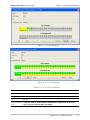
Figure 3-10. Bandwidth Allocation Dialog Box
Table 3-7. Bandwidth Allocation Parameters
Parameter
Possible Values / Remarks
Location
Near-End, Far-End
SHDSL Mode
STU-C, STU-R
Far-End Modem
Type
Unknown, ASMi-52, ASMi-52 Master, ASMi-52 Slave, ASMi-52/CD, ASMi-52/CQ,
LRS-52, FCD-IP, FCD-IPM, D8SL, MP-SHDSL
Rate
ETH
Enabled when a data port is Ethernet.
Select the required data rate from the available values. See Table 3-8 and Table 3-9 for
the available data rates
DTE
Enabled when a data port is Serial DTE.
Select the required data rate from the available values. See Table 3-8 and Table 3-9 for
the available data rates
In order to increase the possible bandwidth allocation user lower E1/T1 timeslots.
E1/T1
Enabled when a data port is E1/T1.
Select the required data rate from the available values. See Table 3-8 and Table 3-9 for
the available data rates
TSA
Click <TSA> to open the Time Slot Assignments dialog box
Far-End E1 TSs
0...31
This parameter is used to define the time slots when the remote modem is not
connected, or is an ASMi-52 multiplexer unit.
This parameter is available in version 2.5 and above units only.
Set the parameter when the local modem is STU-C and E1 line type is unframed
[Set]
Click <Set> to set the modem configuration parameters
[Cancel]
Click <Cancel> to close the Modem Parameters dialog box
[Refresh]
Click <Refresh> to update the Modem Parameters dialog box
Modem Level – Configuration Menu
3-9
RADview-EMS ASMi-52 User’s Manual
Chapter 3 Configuration Management
Table 3-8. ASMi-52 Data Rates
DTE Interface and Clock Mode
Line Interface
Local ASMi-52
Remote ASMi-52
2-wire
4-wire
Serial DTE interface,
internal clock
Serial DTE interface
n × 64 kbps (n = 1, 2, … 32, 36)
n × 128 kbps (n = 1, 2, …32, 36)
Serial DTE interface,
external clock
Serial DTE interface
n × 64 kbps (n = 1, 2, …, 36)
n × 128 kbps (n = 1, 2, …, 36)
Serial DTE interface
E1 DTE interface
n × 64 kbps (n = 3, 4, …, 32)
n × 128 kbps (n = 3, 4, …, 16)
E1 DTE interface
Serial DTE interface
n × 64 kbps (n = 3, 4, …, 32)
n × 128 kbps (n = 3, 4, …, 16)
E1 DTE interface
E1 DTE interface
n × 64 kbps (n = 1, 2, …, 32)
n × 64 kbps (n = 1, 2, …, 32)
T1 DTE interface
T1 DTE interface
n × 64 kbps (n = 1, 2, …, 24)
n × 64 kbps (n = 1, 2, …, 24)
Multiplexer
Serial/E1 DTE
(any) interface
n × 64 kbps (n = 1, 2, …, 32)
n × 64 kbps (n = 1, 2, …, 32)
Table 3-9. ASMi-52 Data Rates (Low Speed Mode)
Unit and DTE Interface Type
Local Unit
ASMi-52 in low
speed mode
Line Interface
Remote Unit
2-wire
4-wire
ASMi-52 in low
speed mode
n × 64 kbps (n = 1, 2, …, 32)
n × 64 kbps (n = 1, 2, …, 32)
ASMi-52 with serial
DTE interface
n × 64 kbps (n = 3, 4, …, 32)
n × 128 kbps (n = 3, 4, …, 16)
ASMi-52 with E1
DTE interface
n × 64 kbps (n = 1, 2, …, 32)
n × 64 kbps (n = 1, 2, …, 32)
Defining the Time Slot Assignment
The TS Assignment command enables you to define the time slots at the E1 and
T1 port levels.
Note
All time slot values for the FE modem are read-only.
To define the time slot at the E1 and T1 port levels:
1. At the modem level, select Configuration > Bandwidth Allocation…
2. Click TSA... in the E1/T1 field.
3. Configure the desired parameters and click <OK>.
3-10
Modem Level – Configuration Menu
RADview-EMS ASMi-52 User’s Manual
Chapter 3 Configuration Management
Figure 3-11. T1 TSA Dialog Box
Figure 3-12. E1 TSA Dialog Box
Table 3-10. E1 (or T1) TSA Parameters
Parameter
Possible Values / Remarks
Location
Near-End, Far-End
SHDSL Mode
STU-C, STU-R
Port
E1, T1
Far-End Modem
Type
Unknown, ASMi-52, ASMi-52 Master, ASMi-52 Slave, ASMi-52/CD, ASMi-52/CQ,
LRS-52, FCD-IP, FCD-IPM, D8SL, MP-SHDSL
Modem Level – Configuration Menu
3-11
Chapter 3 Configuration Management
RADview-EMS ASMi-52 User’s Manual
Parameter
Possible Values / Remarks
[OK]
Click <OK> to set the time slot configuration parameters as displayed in the Near End
Modem and Far End Modem tables
Note: This button is disabled if only one port is supported
Note: If you remove all table values of type Mng TS, a warning message will appear
indicating that the Agent may be disconnected
[Cancel]
Click <Cancel> to close the E1 (or T1) TSA dialog box
[Group…]
Click <Group…> to define time slot groups
Note: This button is only enabled when no table cell is selected
Refer to Defining Time Slot Groups
[Data]
Click <Data> to change the TS type of the selected time slot to Data
Note: This button is only enabled when a lower gray table cell is selected
[Mng]
Click <Mng> to change the TS type of the selected time slot to Mng
Note: This button is only enabled when the Inband Mng value in the Port Parameters
Dialog Box is not None, and when a lower gray table cell is selected
Refer to Configuring the Parameters for the E1 Port
[Disconnect]
Click <Disconnect> to remove a time slot connection
Note: This button is only enabled when a yellow or green table cell is selected
[Reset All]
Click <Reset All> to remove all time slot connections
Note: A warning message will appear
[Refresh]
Click <Refresh> to update the data in the E1 (or T1) TSA dialog box
Defining Time Slot Groups
The Group button enables you to define time slot groups.
Note
This command is not available for the FE modem.
To define time slot groups:
1. At the modem level, select Configuration > Bandwidth Allocation…
2. Click TSA... in the E1/T1 field.
3. Click <Group…>.
4. Configure the desired parameters and click <OK>.
3-12
Modem Level – Configuration Menu
RADview-EMS ASMi-52 User’s Manual
Chapter 3 Configuration Management
Figure 3-13. Group Connection Dialog Box
Table 3-11. Group Connection Parameters
Parameter
Possible Values / Remarks
Connect
All
Click the radio button to the left of <All> to transfer all time slots to the G.SHDSL line
Note: The No. of TSs and Start TS fields will be disabled
Sequence
Click the radio button to the left of <Sequence> to specify a specific time slot sequence
Note: The No. of TSs and Start TS fields will be enabled
Start TS
The first time slot in the group
1…31 (E1)
1…24 (T1)
Default: 1
Note: If the Line Type value in the Port Parameters Dialog Box is E1-MF (G732S) or
E1-CRC-MF (G732SCRC), you cannot select the value 16 for this field
Refer to Configuring the Parameters for the E1 Port
No. of TSs
The total number of time slots in the group
1…31 (E1)
1…24 (T1)
Default: 1
[OK]
Click <OK> to set the time slot group parameters
[Cancel]
Click <Cancel> to close the Group Connection dialog box
Configuring the LAN
The LAN Configuration command enables you to configure the LAN.
Note
This command is not available for an unmanaged FE modem.
To configure the LAN:
1. At the modem level, select Configuration > LAN Configuration…
2. Configure the desired parameters and click <Set>.
Modem Level – Configuration Menu
3-13
RADview-EMS ASMi-52 User’s Manual
Chapter 3 Configuration Management
Figure 3-14. LAN Configuration Dialog Box
Table 3-12. LAN Configuration Parameters
Parameter
Possible Values / Remarks
Location
Near-End, Far-End
SHDSL Mode
STU-C, STU-R
Far-End Modem
Type
Unknown, ASMi-52, ASMi-52 Master, ASMi-52 Slave, ASMi-52/CD, ASMi-52/CQ,
LRS-52, FCD-IP, FCD-IPM, D8SL, MP-SHDSL
Operation Mode
Bridge
Note: This field is read-only
Aging Time (sec)
10…1000000
Default: 10
Note: This field is disabled when the Operation Mode is Transparent
Bridging Mode
Access & Switch, Access Only
Default: Access & Switch
Note: This field is read-only
[Set]
Click <Set> to update the Aging Timeout (sec) and Operation Mode fields
[Cancel]
Click <Cancel> to close the LAN Configuration dialog box
[Refresh]
Click <Refresh> to update the data in the LAN Configuration dialog box
Configuring the Bridging Table
The Bridging Table command enables you to configure the Bridging Table.
Note
This command is not available for an unmanaged FE modem.
To configure the Bridging Table:
1. At the modem level, select Configuration > Bridging Table…
2. Configure the desired parameters and click <Set>.
3-14
Modem Level – Configuration Menu
RADview-EMS ASMi-52 User’s Manual
Chapter 3 Configuration Management
Figure 3-15. Bridging Table Dialog Box
Modem Level – Configuration Menu
3-15
RADview-EMS ASMi-52 User’s Manual
Chapter 3 Configuration Management
Table 3-13. Bridging Table Parameters
Parameter
Possible Values / Remarks
Location
Near-End, Far-End
SHDSL Mode
STU-C, STU-R
Far-End Modem
Type
Unknown, ASMi-52, ASMi-52 Master, ASMi-52 Slave, ASMi-52/CD, ASMi-52/CQ,
LRS-52, FCD-IP, FCD-IPM, D8SL, MP-SHDSL
Mac Address
MAC address of the bridging table
Port
LAN, SHDSL, E1 or T1
Type
Learned, Static
[Add…]
Click <Add> to add a static entry to the Bridging Table
Refer to Adding a Static Entry to the Bridging Table
[Remove]
Click <Remove> to delete a selected static entry from the Bridging Table
[Remove All]
Click <Remove All> to remove all selected static entries
[Close]
Click <Close> to close the Bridging Table dialog box
[Refresh]
Click <Refresh> to update the data in the Bridging Table dialog box
Adding a Static Entry to the Bridging Table
The Add button in the Bridging Table dialog box enables you to add a static entry
to the table.
To add a static entry to the Bridging Table:
1. At the modem level, select Configuration > Bridging Table…
2. Click <Add…> in the Bridging Table dialog box.
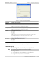
Figure 3-16. Bridging Table: Add Static Entry Dialog Box
Table 3-14. Bridging Table: Add Static Entry Parameters
Parameter
Possible Values / Remarks
Mac Address
(Hex)
MAC address of the static entry
Port
LAN (Near-End), SHDSL (Near-End), E1/T1 (Near-End)
Default: LAN (Near-End)
Note: This field displays a value only when a port physically exists in the modem
[Apply]
Click <Apply> to add the new entry to the Bridging Table
[Close]
Click <Close> to close the Bridging Table: Add Static Entry dialog box
3-16
Modem Level – Configuration Menu
RADview-EMS ASMi-52 User’s Manual
Chapter 3 Configuration Management
Configuring QoS Mapping
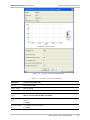
Figure 3-17. QoS Mapping Dialog Box
Table 3-15. QoS Mapping Parameters
Parameter
Possible Values / Remarks
Location
Near-End, Far-End
SHDSL Mode
STU-C, STU-R
Far-End Modem
Type
Unknown, ASMi-52, ASMi-52 Master, ASMi-52 Slave, ASMi-52/CD, ASMi-52/CQ,
LRS-52, FCD-IP, FCD-IPM, D8SL, MP-SHDSL
Classification
802.1p
Mapping
User Priority
0…7
Traffic Class
0…3
[Set]
Click <Set> to update the Traffic Class field
[Traffic Class]
When clicked this opens a sub-menu with the following values:
0 (= High)
1
2
3 (=Low)
Selecting one of these sub-entries updates the Traffic Class value of the selected cell.
Note: This field is only enabled when a cell is selected.
[Cancel]
Click <Cancel> to close the QoS Mapping dialog box
[Refresh]
Click <Refresh> to update the QoS Mapping dialog box
Modem Level – Configuration Menu
3-17
Chapter 3 Configuration Management
RADview-EMS ASMi-52 User’s Manual
Resetting the Configuration
The Reset command enables you to reset the modem hardware, the modem
configuration, and the modem line.
Note
These commands are not available for an unmanaged or unknown FE modem.
Resetting the Modem Hardware
The Reset > Modem HW command enables you to reset the modem hardware.
To reset the modem hardware:
•
At the modem level, select Configuration > Reset > Modem HW.
The modem hardware is reset.
Resetting the Modem Configuration
The Reset > Configuration command enables you to reset the modem
configuration.
To reset the modem configuration:
•
At the modem level, select Configuration > Reset > Configuration.
The modem configuration is reset.
Resetting the Line Configuration
The Reset > Line command enables you to reset the line configuration.
To reset the line configuration:
•
At the modem level, select Configuration > Reset > Line.
The line configuration is reset.
3.4 Modem Level – Diagnostics Menu
The modem level Diagnostics menu allows you to test modem diagnostics.
Figure 3-18. Modem Level Diagnostics Menu
Testing the Modem Diagnostics
The Test command enables you to test the modem diagnostics.
Note
This command is not available for the FE modem.
To test the modem diagnostics:
•
3-18
At the modem level, select Diagnostics > Test…
Modem Level – Diagnostics Menu
RADview-EMS ASMi-52 User’s Manual
Chapter 3 Configuration Management
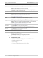
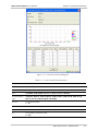
Figure 3-19. Test Dialog Box
Table 3-16. Test Parameters
Parameter
Possible Values / Remarks
Location
Near-End, Far-End
SHDSL Mode
STU-C, STU-R
Far-End Modem
Type
Unknown, ASMi-52, ASMi-52 Master, ASMi-52 Slave, ASMi-52/CD, ASMi-52/CQ,
LRS-52, FCD-IP, FCD-IPM, D8SL, MP-SHDSL
Current Test
The test currently running on the port
Activate Test
None, E1 RLB or T1 RLB, E1 LLB or T1 LLB, IR RLB, IR LLB, E1+IR RLB or T1+IR
RLB, E1+IR LLB or T1+IR LLB, RLB, LLB, BERT, BERT+RLB
Note: Before running a new test, you must click <Stop> to stop the current test
Note: You can only run a new test when the Current Test value is None
Test Duration (min)
The amount of time the test will run (in minutes)
Unchecked (Test Duration disabled), Checked (Test Duration enabled)
1…4095
Note: If you insert a value outside the above range, the Status Bar will display an error
message
Test Initiator
None, User, DTE
BERT Pattern
2E15-1, Alternate, Mark, Space
[Stop]
Click <Stop> to stop the test
Note: This button is enabled only when the Test Initiator value is User
[Apply]
Click <Apply> to run the test
Note: This button is only enabled when no test is currently running on both modems or
if BERT is running on the FE modem and BERT is selected for the NE modem.
[Close]
Click <Close> to close the Test dialog box
[Refresh]
Click <Refresh> to update the Test dialog box
Modem Level – Diagnostics Menu
3-19
RADview-EMS ASMi-52 User’s Manual
Chapter 3 Configuration Management
Configuring BERT Testing
The BERT Counters command enables you to test the circuit diagnostics.
Note
This command is not available for the FE modem.
To test the circuit diagnostics:
•
At the modem level, select Diagnostics > BERT Counters…
Figure 3-20. BERT Counters Dialog Box
Table 3-17. BERT Counters Parameters
Parameter
Possible Values / Remarks
Location
Near-End, Far-End
SHDSL Mode
STU-C, STU-R
Far-End Modem
Type
Unknown, ASMi-52, ASMi-52 Master, ASMi-52 Slave, ASMi-52/CD, ASMi-52/CQ,
LRS-52, FCD-IP, FCD-IPM, D8SL, MP-SHDSL
BERT Pattern
2E15-1, Alternate, Mark, Space
Sync Status
Sync Loss, Sync
BERT Counters
Current – Displays the new updated counters
Delta – Displays the difference between the new counter and the last counter
3-20
Modem Level – Diagnostics Menu
RADview-EMS ASMi-52 User’s Manual
Parameter
Run Time
(sec)
Errored
Seconds
Chapter 3 Configuration Management
Possible Values / Remarks
Time elapsed since BERT started to run (sec)
Number of errored seconds detected since BERT started to run
Sync Loss (sec) Number of times Sync Loss was detected since BERT started to run
Error Bits
Number of Error Bits detected since BERT started to run
BERT Result
Number of Error Bits divided by the total number of bits
Inject Error
Command
[Single]
[Polling]
Note: This group only exists for the NE modem
Click <Single> to inject errors to the FE modem
Click <Polling> to open the Polling Interval dialog box.
Select the polling interval in seconds and click <Set> to accept the change
[Close]
Click <Close> to close the BERT Counters dialog box
[Refresh]
Click <Refresh> to refresh the BERT Counters dialog box
3.5 SHDSL Link Port Level – Configuration Menu
The Configuration menu enables you to configure at the SHDSL Link port level.
Figure 3-21. SHSDL Link Port Level Configuration Menu
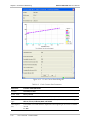
Configuring the SHDSL Link Port Parameters
The Parameters command enables you to configure the SHDSL Link port
parameters.
To configure the SHDSL Link port parameters:
1. At the SHDSL Link port level, select Configuration > Parameters…
2. Configure the desired parameters and click <Set>.
SHDSL Link Port Level – Configuration Menu
3-21
RADview-EMS ASMi-52 User’s Manual
Chapter 3 Configuration Management
Figure 3-22. Port Parameters Dialog Box
Table 3-18. SHDSL Link Port Parameters
Parameter
Possible Values / Remarks
Location
Near-End, Far-End
SHDSL Mode
STU-C, STU-R
Port
CONTROL, ETH, SHDSL Link, E1, T1, DTE (V.35, X.21, RS-530)
Far-End Modem
Type
Unknown, ASMi-52, ASMi-52 Master, ASMi-52 Slave, ASMi-52/CD, ASMi-52/CQ,
LRS-52, FCD-IP, FCD-IPM, D8SL, MP-SHDSL
SHDSL
Transmission Mode
Annex A, Annex B
EOC Compatible
Proprietary, Standard
Note: This field is read-only for the FE modem
Note: This field is read-only
Power Backoff
3-22
Enable, Disable
SHDSL Link Port Level – Configuration Menu
RADview-EMS ASMi-52 User’s Manual
Parameter
Possible Values / Remarks
Line Probe Enable
Enable, Disable
Chapter 3 Configuration Management
Note: This field is enabled for a 2-wire NE modem with a SHDSL Mode of type STU-C
Note: This field is read-only for the FE modem
Current SNR
Margin (dB)
Unchecked (Current SNR Margin disabled),
Checked (Current SNR Margin enabled)
-10…+10
Note: This field is read-only for the NE modem, or when the Line Probe is disabled
Worst Case SNR
Margin (dB)
Unchecked (Worst Case SNR Margin disabled),
Checked (Worst Case SNR Margin enabled)
-10…+10
Note: This field is read-only for the NE modem, or when the Line Probe is disabled
Symmetric, Asymmetric
Power Spectral
Density (PSD) Mask
Note: This field is read-only for the FE modem, or for a modem with an SHDSL Mode of
STU-C and when the Line Probe is disabled
Loop Attenuation
Threshold (dB)
Unchecked (Loop Attenuation Threshold disabled),
Checked (Loop Attenuation Threshold enabled)
1…127
Note: This field is read-write only when the SHDSL Mode is STU-C
SNR Margin
Threshold (dB)
Unchecked (SNR Margin Threshold disabled),
Checked (SNR Margin Threshold enabled)
1…15
Note: This field is read-write only when the SHDSL Mode is STU-C
[Set]
Click <Set> to set the port configuration parameters
[Cancel]
Click <Cancel> to close the Port Parameters dialog box
[Refresh]
Click <Refresh> to update the Port Parameters dialog box
Viewing the SHDSL Link Port Status Configuration
The Status command enables you to view the SHDSL Link port status configuration.
Note
This command does not display status values for the FE modem.
To view the SHDSL Link port status configuration:
• At the SHDSL Link port level, select Configuration > Status…
SHDSL Link Port Level – Configuration Menu
3-23
RADview-EMS ASMi-52 User’s Manual
Chapter 3 Configuration Management
Figure 3-23. Port Status Dialog Box
Table 3-19. Port Status Parameters
Parameter
Possible Values / Remarks
Location
Near-End, Far-End
SHDSL Mode
STU-C, STU-R
Port
CONTROL, ETH, SHDSL Link, E1, T1, DTE (V.35, X.21, RS-530)
Far-End Modem
Type
Unknown, ASMi-52, ASMi-52 Master, ASMi-52 Slave, ASMi-52/CD, ASMi-52/CQ,
LRS-52, FCD-IP, FCD-IPM, D8SL, MP-SHDSL
Connected
Modem/Port No:
For an LRS Quad card, FE modem number 1…4
For a DXC DSL card, external port number 1…n
For a MP MSL card, external port number 1…n
For an LRS-52 modem, 1…24
All other modems, NA
Note: This field is only visible for a NE modem connected to one of the above options
Line Rate (Kbps)
The line rate of the port (in kilobytes per second)
Tip Ring
Normal, Reversed
Line Status
No Sync, Sync
SHDSL State
Idle Mode, Data Mode, Boot Upload, Boot Upload Done, Startup Handshake in
Progress, Startup Training in Progress, Framer Sync in Progress, Local Analog
Loopback in Progress, Remote Core Loopback in Progress, Local Digital Loopback
in Progress, Spectrum Test in Progress
3-24
SHDSL Link Port Level – Configuration Menu
RADview-EMS ASMi-52 User’s Manual
Chapter 3 Configuration Management
Parameter
Possible Values / Remarks
Loop Attenuation
(dB)
0…127
SNR Margin (dB)
0…15
Tx Power (dBm)
The Tx Power of the port, in the format x.y
1…6500.0
Power Back Off
(dB)
0…6
[Close]
Click <Close> to close the Port Status dialog box
[Refresh]
Click <Refresh> to update the Port Status dialog box
3.6 Ethernet Port Level – Configuration Menu
The Configuration menu enables you to configure at the ETH port level.
Figure 3-24. ETH Port Level Configuration Menu
Configuring the ETH Port Parameters
The Parameters command enables you to configure the ETH port parameters.
To configure the ETH port parameters:
1. At the ETH port level, select Configuration > Parameters…
2. Configure the desired parameters and click <Set>.
Figure 3-25. Port Parameters Dialog Box
Ethernet Port Level – Configuration Menu
3-25
RADview-EMS ASMi-52 User’s Manual
Chapter 3 Configuration Management
Table 3-20. Ethernet Port Parameters
Parameter
Possible Values / Remarks
Location
Near-End, Far-End
SHDSL Mode
STU-C, STU-R
Port
CONTROL, ETH, SHDSL Link, E1, T1, DTE (V.35, X.21, RS-530)
Far-End Modem
Type
Unknown, ASMi-52, ASMi-52 Master, ASMi-52 Slave, ASMi-52/CD, ASMi-52/CQ,
LRS-52, FCD-IP, FCD-IPM, D8SL, MP-SHDSL
MAC Address
MAC address of the ETH port
Auto Negotiation
(NE modem only)
Enable, Disable
Max Capability
Advertised
(NE modem only)
10 Base-T Half Duplex, 10 Base-T Full Duplex, 100 Base-TX Half Duplex,
100 Base-TX Full Duplex
Default Type
(NE modem only)
10 Base-T Half Duplex, 10 Base-T Full Duplex, 100 Base-TX Half Duplex,
100 Base-TX Full Duplex
Note: This field is available only if the auto-negotiation is enabled
Note: This field is available only if the auto-negotiation is disabled
[Set]
Click <Set> to set the port configuration parameters
[Cancel]
Click <Cancel> to close the Parameters dialog box
[Refresh]
Click <Refresh> to update the Parameters dialog box
3.7 E1 and T1 Port Levels – Configuration Menu
The Configuration menu enables you to configure at the E1 and T1 port levels.
Figure 3-26. E1 (or T1) Port Level Configuration Menu
Configuring the Parameters for the E1 Port
The Parameters command enables you to configure the E1 port parameters.
To configure the parameters for the E1 port:
1. At the E1 port level, select Configuration > Parameters…
2. Configure the desired parameters and click <Set>.
3-26
E1 and T1 Port Levels – Configuration Menu
RADview-EMS ASMi-52 User’s Manual
Chapter 3 Configuration Management
Figure 3-27. Port Parameters Dialog Box
E1 and T1 Port Levels – Configuration Menu
3-27
RADview-EMS ASMi-52 User’s Manual
Chapter 3 Configuration Management
Table 3-21. Port Parameters
Parameter
Possible Values / Remarks
Location
Near-End, Far-End
SHDSL Mode
STU-C, STU-R
Port
CONTROL, ETH, SHDSL Link, E1, T1, DTE (V.35, X.21, RS-530)
Far-End Modem
Type
Unknown, ASMi-52, ASMi-52 Master, ASMi-52 Slave, ASMi-52/CD, ASMi-52/CQ,
LRS-52, FCD-IP, FCD-IPM, D8SL, MP-SHDSL
Line Type
The line type of the E1 port
Unframed, E1 (G732N), E1-CRC (G732N-CRC), E1-MF (G732S)
Note: This field is read-only for the FE modem
Identical settings
Whether the configuration settings are the same for the FE modem
No, Yes
Note: This field is read-only for the FE modem
TS0 Mode
The time slot mode of the port
Looped, Transparent
Note: This field is read-only for the FE modem
Sync Mode
The synchronization mode of the E1 port
TR-62411, CCITT, FAST
Note: This field is read-only for the FE modem
Idle Code (hex)
The idle code of the E1 port
0…FF
Note: This field is read-only for the FE modem
Dedicated TS
Configuration
Inband Mng
The inband management type of the DTS configuration
None, Dedicated TS/FR
Note: This field is unavailable for the FE modem
Tx to Remote
Disable, Enable
Note: This field is available for the FE modem when it is connected to an E1
[Set]
Click <Set> to set the port configuration parameters
Note: If you change the Line Type value to Unframed or the Same Far End Settings value
to Yes (when the SHDSL Mode is of type STU-R), a confirmation message will appear
indicating that the time slot assignment will be deleted
Note: If you change one of the DTS Configuration values, a confirmation message will
appear indicating that the Agent may be disconnected
[Cancel]
Click <Cancel> to close the Port Parameters dialog box
[Refresh]
Click <Refresh> to update the Port Parameters dialog box
3-28
E1 and T1 Port Levels – Configuration Menu
RADview-EMS ASMi-52 User’s Manual
Chapter 3 Configuration Management
Configuring the Parameters for the T1 Port
The Parameters command enables you to configure the T1 port parameters.
To configure the parameters for the T1 port:
1. At the T1 port level, select Configuration > Parameters…
2. Configure the desired parameters and click <Set>.
Table 3-22. Port Parameters
Parameter
Possible Values / Remarks
Location
Near-End, Far-End
SHDSL Mode
STU-C, STU-R
Port
CONTROL, ETH, SHDSL Link, E1, T1, DTE (V.35, X.21, RS-530)
Far-End Modem
Type
Unknown, ASMi-52, ASMi-52 Master, ASMi-52 Slave, ASMi-52/CD, ASMi-52/CQ,
LRS-52, FCD-IP, FCD-IPM, D8SL, MP-SHDSL
Line Type
The line type of the T1 port
Unframed, ESF, D4 (SF)
Line Code
The line code of the T1 port
B8ZS, AMI
Rx Gain
The Rx gain of the T1 port
Short Haul, Long Haul
Line Mode
The line mode of the T1 port
CSU, DSU
Tx Gain (dB)
The Tx gain of the T1 port
7.5, 15.0, 22.5
Note: This field is only enabled when the Line Mode value is “CSU”
Line Length (ft)
0-133, 134-266, 267-399, 400-533, 534-655
Note: This field is only enabled when the Line Mode value is “DSU”
Identical Settings
Whether the FE settings for the two ends of the T1 port line are the same
No, Yes
Sync Mode
The synchronization mode of the T1 port
TR-62411, CCITT, FAST
Idle Code (hex)
The idle code of the T1 port
0…FF
Signaling Mode
None, Robbed Bit
Dedicated TS
Configuration
Inband Mng
The inband management type of the DTS configuration
None, Dedicated TS/FR
Tx to Remote
Disable, Enable
Note: This field is available for the FE modem when it is connected to an E1
E1 and T1 Port Levels – Configuration Menu
3-29
Chapter 3 Configuration Management
RADview-EMS ASMi-52 User’s Manual
Parameter
Possible Values / Remarks
[Set]
Click <Set> to set the port configuration parameters
Note: If you changed the Line Type value to “Unframed” or the Same Far End Settings
value to “Yes”, then a confirmation message appears indicating that the time slot
assignment will be deleted
Note: If you changed one of the DTS Configuration values, a confirmation message
appears indicating that these changes may disconnect the Agent
[Cancel]
Click <Cancel> to cancel the setting of the port configuration parameters
[Refresh]
Click <Refresh> to update the data in the Port Parameters dialog box
3.8 DTE (V.35, RS-530) Port Level – Configuration Menu
The Configuration menu enables you to configure at the DTE (V.35, RS-530) port
level.
Figure 3-28. DTE (V.35, RS-530) Level Configuration Menu
Configuring the DTE (V.35, RS-530) Port Parameters
The Parameters command enables you to configure the parameters for the DTE
(V.35, RS-530) port.
Note
This command is not available for the DTE (X.21) port.
Note
The Enable LLB from DTE and Enable RLB from DTE checkboxes that appear below
are disabled for the FE modem when it is unmanaged or unknown.
To configure the port parameters:
1. At the DTE (V.35, RS-530) port level, select Configuration > Parameters…
2. Configure the desired parameters and click <Set>.
3-30
DTE (V.35, RS-530) Port Level – Configuration Menu
RADview-EMS ASMi-52 User’s Manual
Chapter 3 Configuration Management
Figure 3-29. DTE (V.35, RS-530) Port Parameters Dialog Box
Table 3-23. DTE (V.35, RS-530) Port Parameters
Parameter
Possible Values / Remarks
Location
Near-End, Far-End
SHDSL Mode
STU-C, STU-R
Port
CONTROL, ETH, SHDSL Link, E1, T1, DTE (V.35, RS-530)
Far-End Modem
Type
Unknown, ASMi-52, ASMi-52 Master, ASMi-52 Slave, ASMi-52/CD, ASMi-52/CQ,
LRS-52, FCD-IP, FCD-IPM, D8SL, MP-SHDSL
Enable LLB from
DTE
Enables the local loop back option for the data terminal equipment
Enable RLB from
DTE
Enables the remote loop back option for the data terminal equipment
[Set]
Click <Set> to set the port configuration parameters
[Cancel]
Click <Cancel> to cancel the setting of the port configuration parameters
[Refresh]
Click <Refresh> to update the data in the DTE (V.35, RS-530) Port Parameters dialog
box
Unchecked (disabled)
Checked (enabled)
Unchecked (disabled)
Checked (enabled)
3.9 CONTROL Port Level – Configuration Menu
The Configuration menu enables you to configure at the CONTROL port level.
Figure 3-30. CONTROL Port Level Configuration Menu
CONTROL Port Level – Configuration Menu
3-31
RADview-EMS ASMi-52 User’s Manual
Chapter 3 Configuration Management
Configuring the CONTROL Port Parameters
The Parameters command enables you to configure the CONTROL port
parameters.
Note
This command is not available for the FE modem.
To configure the CONTROL port parameters:
1. At the CONTROL port level, select Configuration > Parameters…
2. Configure the desired parameters and click <Set>.
Figure 3-31. Port Parameters Dialog Box
3-32
CONTROL Port Level – Configuration Menu
RADview-EMS ASMi-52 User’s Manual
Chapter 3 Configuration Management
Table 3-24. Port Parameters
Parameter
Possible Values / Remarks
Location
Near-End, Far-End
SHDSL Mode
STU-C, STU-R
Port
CONTROL
Far-End Modem
Type
Unknown, ASMi-52, ASMi-52 Master, ASMi-52 Slave, ASMi-52/CD, ASMi-52/CQ,
LRS-52, FCD-IP, FCD-IPM, D8SL, MP-SHDSL
Rate (bps)
The rate of the CONTROL port (in bits per second)
9600, 19200, 38400, 57600, 115200
Data Bits
7, 8
Parity
None, Odd, Even
CTS
ON, RTS
Interface
DCE, DTE
DCD Delay (msec)
0, 10, 50, 100, 200, 300 (in milliseconds)
Note: This field is disabled when the Interface value is DCE
DSR
ON, DTE
Note: This field is disabled when the Interface value is DTE
Mode
Terminal, Dial Out, NMS SLIP, SMS PPP
Call Out Mode
None, All, Major
Dial Retries
0…8
Wait for Connect
(sec)
30, 45, 60
Dial Mode
Tone, Pulse
Primary Dial No.
Note: The maximum number of characters for this field is 20
Alternate No. Use
No, Yes
Alternate Dial No.
Note: The maximum number of characters for this field is 20
[Set]
Click <Set> to set the port configuration parameters
[Cancel]
Click <Cancel> to close the Port Parameters dialog box
[Refresh]
Click <Refresh> to update the Port Parameters dialog box
3.10
Repeater Level – Configuration Menu
The Configuration menu enables you to configure at the repeater level.
Figure 3-32. Repeater Level Configuration Menu
Repeater Level – Configuration Menu
3-33
RADview-EMS ASMi-52 User’s Manual
Chapter 3 Configuration Management
Configuring the Repeater Parameters
The Parameters command enables you to configure the repeater parameters.
To configure the repeater parameters:
1. At the repeater level, select Configuration > Parameters…
2. Configure the desired parameters and click <Set>.
Figure 3-33. Repeater Parameters Dialog Box{need new graphic}
Table 3-25. Repeater Parameters
Parameter
Possible Values / Remarks
Repeater
1…8
Wiring
2 Wire, 4 Wire
Loop Attenuation
Threshold (dB)
Unchecked (Loop Attenuation Threshold disabled),
Checked (Loop Attenuation Threshold enabled)
1…127
Note: This field is read-write when the SHDSL Mode is STU-C and read-only when the
SHDSL Mode is STU-R
SNR Margin
Threshold (dB)
Unchecked (SNR Margin Threshold disabled),
Checked (SNR Margin Threshold enabled)
1…15
Note: This field is read-write when the SHDSL Mode is STU-C and read-only when the
SHDSL Mode is STU-R
[Set]
Click <Set> to set the repeater configuration parameters
[Cancel]
Click <Close> to close the Repeater Parameters dialog box
[Refresh]
Click <Refresh> to update the Repeater Parameters dialog box
3-34
Repeater Level – Configuration Menu
RADview-EMS ASMi-52 User’s Manual
Chapter 3 Configuration Management
Resetting the Repeater Network Side
The Reset Network Side command enables you to reset the repeater network
side.
To reset the repeater network side:
1. In the RADview ASMi-52 window, select one of the three repeaters.
2. Select Configuration > Reset Network Side.
The repeater network side is reset.
3.11
Repeater Level – Diagnostics Menu
The repeater level Diagnostics menu allows you to test repeater diagnostics.
Figure 3-34. Repeater Level Diagnostics Menu
Testing the Repeater Diagnostics
The Test command enables you to test the repeater diagnostics.
To test the repeater diagnostics:
•
At the repeater level, select Diagnostics > Test…
Figure 3-35. Repeater Test Dialog Box
Table 3-26. Repeater Test Parameters
Parameter
Possible Values / Remarks
Repeater
1…8
Repeater Side
Network
Note: This field is read-only
Current Test
None, RLB
Repeater Level – Diagnostics Menu
3-35
Chapter 3 Configuration Management
Parameter
Possible Values / Remarks
Activate Test
None, RLB
Default: RLB
RADview-EMS ASMi-52 User’s Manual
Note: You cannot enter the value None while a test is currently running
Test Duration
(min)(0=forever)
The amount of time the test will last (in minutes)
0…4095
Note: The value 0 indicates that the test will run indefinitely
[Stop]
Click <Stop> to stop the test
Note: This button is only enabled when a test is running on one of the ports
Note: A confirmation message will appear, and the data will be updated
[Apply]
Click <Apply> to run the test
Note: This button is only enabled when a test is not running on one of the ports
Note: A confirmation message will appear, and the data will be updated
[Close]
Click <Close> to close the Repeater Test dialog box
[Refresh]
Click <Refresh> to update the Repeater Test dialog box
3-36
Repeater Level – Diagnostics Menu
Chapter 4
Performance Monitoring
This chapter describes the RADview options for viewing and clearing statistics
information for ASMi-52. These options also include setting the Polling Interval.
4.1 System Level – Statistics Menu
The Statistics menu allows you to set the Polling Interval at the system level.
Figure 4-1. System Level Statistics Menu
Setting the Polling Interval
The Polling Interval command enables you to set the Polling Interval at the system
level.
To set the Polling Interval at the system level:
1. At the system level, select Statistics > Polling Interval…
2. Enter the desired parameter and click <Set>.
Figure 4-2. Polling Interval Dialog Box
Table 4-1. Polling Interval Parameters
Parameter
Possible Values/Remarks
Polling Interval
(sec)
The interval at which the Agent will be polled (in seconds)
5, 10, 15…60
Default: 10
Note: The value you enter will be the interval used for both the current and running Agent
statistics on all ports
[Set]
Click <Set> to set the Polling Interval
[Cancel]
Click <Cancel> to close the Polling Interval dialog box
System Level – Statistics Menu
4-1
RADview-EMS ASMi-52 User’s Manual
Chapter 4 Performance Monitoring
4.2 Modem Level – Statistics Menu
The Statistics menu allows you to clear modem statistics at the modem level.
Figure 4-3. Modem Level Statistics Menu
Clearing Modem Statistics
The Clear Modem Statistics command enables you to clear statistics at the
modem level.
Note
This command is unavailable for the FE modem.
To clear statistics at the modem level:
•
At the modem level, select Statistics > Clear Modem Statistics…
The modem statistics are cleared.
4.3 SHDSL Link Port Level – Statistics Menu
The Statistics menu allows you to view and clear statistics data at the SHDSL Link
port level.
Figure 4-4. SHDSL Link Port Level Statistics Menu
Note
For modems with 2-wire line pairs, the word Line appears in the title bar of the
dialog box. For modems with 4-wire line pairs, the word Line-A or Line-B appears in
the title bar of the dialog box.
Viewing Current 15-Minute Data for the SHDSL Link Port
The Line > 15 min Current Data command enables you to view port data from
the beginning of the current 15-minute interval.
To view port data from the beginning of the current 15-minute interval:
•
4-2
At the SHDSL Link port level, select Statistics > Line > 15 min Current
Data…
SHDSL Link Port Level – Statistics Menu
RADview-EMS ASMi-52 User’s Manual
Chapter 4 Performance Monitoring
Figure 4-5. 15 min Current Data Dialog Box
Table 4-2. 15 min Current Data Parameters
Parameter
Possible Values/Remarks
Location
Near-End, Far-End
SHDSL Mode
STU-C, STU-R
Port
CONTROL, ETH, SHDSL Link, E1, T1, DTE (V.35, X.21, RS-530)
Far-End Modem
Type
Unknown, ASMi-52, ASMi-52 Master, ASMi-52 Slave, ASMi-52/CD, ASMi-52/CQ,
LRS-52, FCD-IP, FCD-IPM, D8SL, MP-SHDSL
Time Elapsed
(sec)
The number of seconds that have elapsed since the beginning of the current 15-minute
interval
0…899
SHDSL Link Port Level – Statistics Menu
4-3
Chapter 4 Performance Monitoring
RADview-EMS ASMi-52 User’s Manual
Table 4-2. 15 min Current Data Parameters (Cont.)
Parameter
Possible Values/Remarks
Errored Seconds
(ES)
The number of errored seconds
0…899
Severely Errored
Seconds (SES)
The number of severely errored seconds
0…899
CRC Anomalies
(CRCA)
The CRC (Cyclical Redundancy Checking) anomalies that have occurred since the
beginning of the current 15-minute interval
Loss of Sync
Word (LOSW)
Seconds
The number of sync word seconds that have been lost
0…899
Unavailable
Seconds (UAS)
The number of unavailable seconds
0…899
[Close]
Click <Close> to close the 15 min Current Data dialog box
[Poll]
Click <Poll> to poll the Agent
Viewing One-Day Current Data for the SHDSL Link Port
The Line > One Day Current Data command enables you to view port data from
the beginning of the current one-day interval.
To view port data from the beginning of the current one-day interval:
•
4-4
At the SHDSL Link port level, select Statistics > Line > One Day Current
Data...
SHDSL Link Port Level – Statistics Menu
RADview-EMS ASMi-52 User’s Manual
Chapter 4 Performance Monitoring
Figure 4-6. One Day Current Data Dialog Box
Table 4-3. One Day Current Data Parameters
Parameter
Possible Values/Remarks
Location
Near-End, Far-End
SHDSL Mode
STU-C, STU-R
Port
CONTROL, ETH, SHDSL Link, E1, T1, DTE (V.35, X.21, RS-530)
Far-End Modem
Type
Unknown, ASMi-52, ASMi-52 Master, ASMi-52 Slave, ASMi-52/CD, ASMi-52/CQ,
LRS-52, FCD-IP, FCD-IPM, D8SL, MP-SHDSL
Time Elapsed
(sec):
The number of seconds that have elapsed since the beginning of the current one-day
interval
0…86399
Errored Seconds
(ES)
The number of errored seconds
0…86399
SHDSL Link Port Level – Statistics Menu
4-5
Chapter 4 Performance Monitoring
RADview-EMS ASMi-52 User’s Manual
Table 4-3 One Day Current Data Parameters (Cont.)
Parameter
Possible Values/Remarks
Severely Errored
Seconds (SES)
The number of severely errored seconds
0…86399
CRC Anomalies
(CRCA)
The CRC (Cyclical Redundancy Checking) anomalies that have occurred since the
beginning of the current one-day interval
Loss of Sync
Word (LOSWS)
Seconds
The number of sync word seconds that have been lost
0…86399
Unavailable
Seconds (UAS)
The number of unavailable seconds
0…86399
[Close]
Click <Close> to close the One Day Current Data dialog box
[Poll]
Click <Poll> to poll the Agent
Viewing 15-Minute Interval Data for the SHDSL Link Port
The Line > 15 min Interval Data command enables you to view port data for all
15-minute intervals over the last 24 hours.
To view port data for all 15-minute intervals over the last 24 hours:
•
4-6
At the SHDSL Link port level, select Statistics > Line > 15 min Interval
Data…
SHDSL Link Port Level – Statistics Menu
RADview-EMS ASMi-52 User’s Manual
Chapter 4 Performance Monitoring
Figure 4-7. 15 min Interval Data Dialog Box
Table 4-4. 15 min Interval Data Parameters
Parameter
Possible Values/Remarks
Location
Near-End, Far-End
SHDSL Mode
STU-C, STU-R
Port
CONTROL, ETH, SHDSL Link, E1, T1, DTE (V.35, X.21, RS-530)
Far-End Modem
Type
Unknown, ASMi-52, ASMi-52 Master, ASMi-52 Slave, ASMi-52/CD, ASMi-52/CQ,
LRS-52, FCD-IP, FCD-IPM, D8SL, MP-SHDSL
Inv. No.
The interval number
1…96
From (hh:mm)
The time the interval began, in the format hh:mm
To (hh:mm)
The time the interval ended, in the format hh:mm
ES
The number of errored seconds
0…899
SHDSL Link Port Level – Statistics Menu
4-7
Chapter 4 Performance Monitoring
RADview-EMS ASMi-52 User’s Manual
Table 4-4. 15 min Interval Data Parameters (Cont.)
Parameter
Possible Values/Remarks
SES
The number of severely errored seconds
0…899
CRC Anomalies
The CRC (Cyclical Redundancy Checking) anomalies that have occurred since the
beginning of the last 24-hour period
LOSWS
The number of sync word seconds that have been lost
0…899
UAS
The number of unavailable seconds
0…899
[Close]
Click <Close> to close the 15 min Interval Data dialog box
Viewing One-Day Interval Data for the SHDSL Link Port
The Line > One Day Interval Data command enables you to view SHDSL Link
port data at one-day intervals.
To view port data at one-day intervals:
•
4-8
At the SHDSL Link port level, select Statistics > Line > One Day Interval
Data…
SHDSL Link Port Level – Statistics Menu
RADview-EMS ASMi-52 User’s Manual
Chapter 4 Performance Monitoring
Figure 4-8. One Day Interval Data Dialog Box
Table 4-5. One Day Interval Data Parameters
Parameter
Possible Values/Remarks
Location
Near-End, Far-End
SHDSL Mode
STU-C, STU-R
Port
CONTROL, ETH, SHDSL Link, E1, T1, DTE (V.35, X.21, RS-530)
Far-End Modem
Type
Unknown, ASMi-52, ASMi-52 Master, ASMi-52 Slave, ASMi-52/CD, ASMi-52/CQ,
LRS-52, FCD-IP, FCD-IPM, D8SL, MP-SHDSL
Days Ago
The number of daily intervals for which data is displayed
1…7
Note: The field is empty when no table entries exist
ES
The number of errored seconds
SES
The number of severely errored seconds
CRC Anomalies
The CRC (Cyclical Redundancy Checking) anomalies that have occurred since the
beginning of the last 24-hour period
SHDSL Link Port Level – Statistics Menu
4-9
RADview-EMS ASMi-52 User’s Manual
Chapter 4 Performance Monitoring
Table 4-5. One Day Interval Data Parameters (Cont.)
Parameter
Possible Values/Remarks
LOSWS
The number of sync word seconds that have been lost
UAS
The number of unavailable seconds
[Close]
Click <Close> to close the One Day Interval Data dialog box
Viewing Accumulated Data for the SHDSL Link Port
The Line > Accumulated Data command enables you to view accumulated port
data.
To view accumulated port data:
•
At the SHDSL Link port level, select Statistics > Line > Accumulated Data…
Figure 4-9. Accumulated Data Dialog Box
4-10
SHDSL Link Port Level – Statistics Menu
RADview-EMS ASMi-52 User’s Manual
Chapter 4 Performance Monitoring
Table 4-6. Accumulated Data Parameters
Parameter
Possible Values/Remarks
Location
Near-End, Far-End
SHDSL Mode
STU-C, STU-R
Port
CONTROL, ETH, SHDSL Link, E1, T1, DTE (V.35, X.21, RS-530)
Far-End Modem
Type
Unknown, ASMi-52, ASMi-52 Master, ASMi-52 Slave, ASMi-52/CD, ASMi-52/CQ,
LRS-52, FCD-IP, FCD-IPM, D8SL, MP-SHDSL
Errored Seconds
(ES)
The number of errored seconds
Severely Errored
Seconds (SES)
The number of severely errored seconds
CRC Anomalies
(CRCA)
The CRC (Cyclical Redundancy Checking) anomalies that have accumulated
Loss of Sync
Word (LOSW)
Seconds
The number of sync word seconds that have been lost
Unavailable
Seconds (UAS)
The number of unavailable seconds
[Close]
Click <Close> to close the Accumulated Data dialog box
[Poll]
Click <Poll> to poll the Agent
Clearing Statistics for the SHDSL Link Port
The Statistics > Clear Statistics command enables you to clear port statistics at
the SHDSL Link port level.
To clear port statistics at the SHDSL Link port level:
•
At the SHDSL Link port level, select Statistics > Clear Statistics…
The statistics for the SHDSL Link port are cleared.
4.4 E1/T1 Port Level – Statistics Menu
The Statistics menu allows you view and clear statistics data at the E1/T1 port
level.
Figure 4-10. E1/T1 Port Level Statistics Menu
E1/T1 Port Level – Statistics Menu
4-11
RADview-EMS ASMi-52 User’s Manual
Chapter 4 Performance Monitoring
Viewing BPV Statistics
The BPV command enables you to view BPV data.
Note
This command is available for the E1 port when the line type is E1-MF (G732S) or
Unframed, or for the T1 port when the line type is D4 (SF) or Unframed.
To view BPV data:
•
At the E1/T1 port level, select Statistics > BPV…
Figure 4-11. BPV Statistics Dialog Box
Table 4-7. BPV Statistics Parameters
Parameter
Possible Values/Remarks
Location
Near-End, Far-End
SHDSL Mode
STU-C, STU-R
Port
CONTROL, ETH, SHDSL Link, E1, T1, DTE (V.35, X.21, RS-530)
Far-End Modem
Type
Unknown, ASMi-52, ASMi-52 Master, ASMi-52 Slave, ASMi-52/CD, ASMi-52/CQ,
LRS-52, FCD-IP, FCD-IPM, D8SL, MP-SHDSL
BPV Last Minute
0…1000
4-12
E1/T1 Port Level – Statistics Menu
RADview-EMS ASMi-52 User’s Manual
Chapter 4 Performance Monitoring
Table 4-7. BPV Statistics Parameters (Cont.)
Parameter
Possible Values/Remarks
BPV Worst
Minute
0…1000
[Close]
Click <Close> to close the BPV Statistics dialog box
[Poll]
Click <Poll> to poll the Agent
Viewing Current 15-Minute Port Data
The 15 min Current Data command enables you to view port data from the
beginning of the current 15-minute interval.
Note
This command is available for the E1 port when the line type is E1-CRC
(G732N-CRC), or for the T1 port when the line type is ESF.
To view port data from the beginning of the current 15-minute interval:
•
At the E1/T1 port level, select Statistics > 15 min Current Data…
E1/T1 Port Level – Statistics Menu
4-13
RADview-EMS ASMi-52 User’s Manual
Chapter 4 Performance Monitoring
Figure 4-12. 15 min Current Data Dialog Box
Table 4-8. 15 min Current Data Parameters
Parameter
Possible Values/Remarks
Location
Near-End, Far-End
SHDSL Mode
STU-C, STU-R
Port
CONTROL, ETH, SHDSL Link, E1, T1, DTE (V.35, X.21, RS-530)
Far-End Modem
Type
Unknown, ASMi-52, ASMi-52 Master, ASMi-52 Slave, ASMi-52/CD, ASMi-52/CQ,
LRS-52, FCD-IP, FCD-IPM, D8SL, MP-SHDSL
Time Elapsed
(sec)
The number of seconds that have elapsed since the beginning of the current 15-minute
interval
0…899
4-14
E1/T1 Port Level – Statistics Menu
RADview-EMS ASMi-52 User’s Manual
Chapter 4 Performance Monitoring
Table 4-8. 15 min Current Data Parameters (Cont.)
Parameter
Possible Values/Remarks
Errored Seconds
(ES)
The number of errored seconds
0…899
Unavailable
Seconds (UAS)
The number of seconds that are unavailable
0…899
Severely Errored
Seconds (SES)
The number of severely errored seconds
0…899
Bursty Errored
Seconds (BES)
The number of bursty errored seconds
0…899
Loss of Frame
(LOFC)
Description of frame loss
Controlled Slip
Seconds (CSS)
The number of controlled slip seconds
0…899
Degraded
Minutes (DM)
The number of degraded minutes
0…15
CRC Error Event
Description of CRC error event
CRC Average
Error Event
Description of CRC average error event
[Close]
Click <Close> to close the 15 min Current Data dialog box
[Poll]
Click <Poll> to poll the Agent
Viewing 15-Minute Interval Port Data
The 15 min Interval Data command enables you to view port data for all
15-minute intervals over the last 24 hours.
Note
This command is available for the E1 port when the line type is E1-CRC
(G732N-CRC), or for the T1 port when the line type is ESF.
To view port data for all 15-minute intervals over the last 24 hours:
•
At the E1/T1 port level, select Statistics > 15 min Interval Data...
E1/T1 Port Level – Statistics Menu
4-15
RADview-EMS ASMi-52 User’s Manual
Chapter 4 Performance Monitoring
Figure 4-13. 15 min Interval Data Dialog Box
Table 4-9. Interval Data Parameters
Parameter
Possible Values/Remarks
Location
Near-End, Far-End
SHDSL Mode
STU-C, STU-R
Port
CONTROL, ETH, SHDSL Link, E1, T1, DTE (V.35, X.21, RS-530)
Far-End Modem
Type
Unknown, ASMi-52, ASMi-52 Master, ASMi-52 Slave, ASMi-52/CD, ASMi-52/CQ,
LRS-52, FCD-IP, FCD-IPM, D8SL, MP-SHDSL
Valid Intervals
The total number of valid intervals since the beginning of the last 24-hour period
0…96
4-16
E1/T1 Port Level – Statistics Menu
RADview-EMS ASMi-52 User’s Manual
Chapter 4 Performance Monitoring
Table 4-9 Interval Data Parameters (Cont.)
Parameter
Possible Values/Remarks
Inv. No.
The interval number
1…96
From
The time the interval began, format hh:mm
To
The time the interval ended, format hh:mm
ES
The number of errored seconds
UAS
The number of unavailable seconds
SES
The number of severely errored seconds
BES
The number of bursty errored seconds
0…899
LOFC
Description of frame loss
CSS
The number of controlled slip seconds
0…899
DM
The number of degraded minutes
0…15
[Close]
Click <Close> to close the Interval Data dialog box
[Poll]
Click <Poll> to poll the Agent
Clearing Statistics for the E1/T1 Port
The Clear Statistics command enables you to clear statistics for the E1/T1 port.
To clear statistics for the E1/T1 port:
•
At the E1/T1 port level, select Statistics > Clear Statistics…
The statistics for the E1/T1 port are cleared.
E1/T1 Port Level – Statistics Menu
4-17
Chapter 4 Performance Monitoring
4-18
E1/T1 Port Level – Statistics Menu
RADview-EMS ASMi-52 User’s Manual
Appendix A
Active Alarms
This appendix lists the active alarms for ASMi-52 fault management at the modem,
port, and repeater levels.
A.1 Modem Level – Active Alarms
At the modem level, active alarms may be displayed at the modem and port levels
combined, or at the modem level alone.
Modem and Port Levels
Table A-1 lists the active alarms at the modem and port levels combined.
Table A-1. Modem Level Active Alarms: Modem and Port Levels Combined
Code
Severity
Description
1
Major
SELF TEST ERROR
Failure occurred while testing the port hardware components
2
Warning
SOFTWARE DOWNLOAD
Port currently performing software download
3
Warning
INBAND LOOP
Inband-activated loopback in progress
4
Warning
LLB FROM DTE
Local loopback activated by physical connector
Note: This alarm will only appear if the V.35 or RS-530 interface is present
5
Warning
RLB FROM DTE
Remote loopback activated by physical connector
Note: This alarm will only appear if the V.35 or RS-530 interface is present
6
Major
PROP PROT FAIL
RAD proprietary protocol between devices failed
7
Major
E1 TS NUM NOT COMP
LRSi card not supported in this device
8
Major
LAN NOT CONNECTED
LAN not connected (for Ethernet interfaces)
9
Minor
LOOP ATTN. OVER LINE A
Loop attenuation exceeded alarm threshold at line A
10
Minor
LOOP ATTN. OVER LINE B
Loop attenuation exceeded alarm threshold at line B
Modem Level – Active Alarms
A-1
RADview-EMS ASMi-52 User’s Manual
Appendix A Active Alarms
Table A-1. Modem Level Active Alarms: Modem and Port Levels Combined (Cont.)
Code
Severity
Description
11
Minor
SNR MARGIN OVER LINE A
SNR margin exceeded alarm threshold at line A
12
Minor
SNR MARGIN OVER LINE B
SNR margin exceeded alarm threshold at line B
13
Minor
LOSW FAILURE OVER LINE A
Forward LOSW alarm occurred at line A
14
Minor
LOSW FAILURE OVER LINE B
Forward LOSW alarm occurred at line B
15
Major
DATA RATE NOT COMPATIBLE
Data rate and line rate are not compatible
Note: This alarm will only appear if the V.35 interface is present
16
Minor
PSD NOT COMPATIBLE
PSD mode set by user is not compatible with the PSD mode in use
17
Major
SYNC LOSS LINE A
G.SHDSL line A not synchronized
18
Major
SYNC LOSS LINE B
G.SHDSL line B not synchronized
Note: This alarm will only appear if the modem is 4 wire
19
Major
MNGMNT IS DOWN
Management between NE and FE is down (EOC problem)
20
Major
ILLEGAL EXTER CLK
Exernal clock not compatible to clock set by user for DTE (not supported in this
device)
21
Minor
CRC ERROR OVER LINE A
Too many CRC errors received on G.SHDSL at line A
22
Minor
CRC ERROR OVER LINE B
Too many CRC errors received on G.SHDSL at line B
23
Major
NO DTE INTERFACE
Device lacks a DTE interface
24
Major
INTERFACE RATE FAIL
Line rate failed to meet one of the following conditions:
— When interface is G704 or G703, line rate may be up to 2048 Kbps, or one
unit up to 2 Mbps and the other unit up to 4 Mbps
— When remote unit is G703, line rate is not 2048 Kbps
25
Major
E1 REMOTE FAILURE
E1 on FE received red alarm
26
Major
E1-TS NOT RATE COMP
Number of connected time slots in E1 line not equal to line rate
27
Major
E1 SIGNAL LOSS
E1 loss of receiving signal occurred
A-2
Modem Level – Active Alarms
RADview-EMS ASMi-52 User’s Manual
Appendix A Active Alarms
Table A-1. Modem Level Active Alarms: Modem and Port Levels Combined (Cont.)
Code
Severity
Description
28
Minor
E1 BPV ERR EXC
Bipolar violation error exceeded threshold
29
Minor
E1 FRAME SLIP EXC
Detected E1 frame slips exceeded threshold
30
Major
E1 EXCESSIVE BPV
Rate of bipolar violations exceeded 1 X 10⁻⁶ for period of 1000 seconds
31
Minor
E1 CRC-4 EXC
Detected CRC-4 errors exceeded threshold
32
Major
E1 EXCESSIVE ERR RATIO
Bit error link rate exceeded 10-3
33
Major
E1 AIS OCCURRED
AIS detected on E1
34
Major
E1 AIS AND SYNC LOSS
AIS and loss of frame alignment occurred on E1
35
Major
E1 SYNC LOSS
Loss of frame synchronization occurred on E1
36
Minor
E1 CRC MF EXC
Detected CRC errors in LRS52 frame synchronization signal exceeded
threshold
37
Major
E1 REMOTE SYNC LOSS
Remote loss of frame synchronization occurred
38
Major
E1 MF SYNC LOSS
Local loss of LRS52 frame synchronization occurred
39
Major
E1 MF REMOTE SYNC LOSS
Remote loss of LRS52 frame synchronization occurred
40
Major
E1 TS NUM NOT X128
For 4 Wire modem, user set time slot with number that is not a multiple of
X 128
Note: This alarm will only appear when both E1 and V.35 interfaces are present
(or any other interface which is not G704)
41
Major
E1 TS NUM NOT COMP
Number of time slots in NE and FE do not correspond
42
Major
WIRE MODE NOT COMP
Line interface types (2 wire and 4 wire) for local and remote units do not
corrrespond
43
Major
SPAN IS NOT FULL
Span containing information on central office, customer premises equipment,
and repeaters is experiencing a problem on one of its segments
50
Major
LINE PARAMETERS NOT COMP
Configuration parameters do not correspond, causing a lack of synchronization
between NE and FE
Modem Level – Active Alarms
A-3
RADview-EMS ASMi-52 User’s Manual
Appendix A Active Alarms
Table A-1. Modem Level Active Alarms: Modem and Port Levels Combined (Cont.)
Code
Severity
Description
51
Major
EXTERNAL TO INTERNAL CLOCK
Clock missing at the external clock source
60
Major
SELF TEST ERROR
Failure occurred while testing the device hardware components
61
Warning
SOFTWARE DOWNLOAD
Device currently performing software download
62
Major
PS1 Fail
Failure occurred in PS 1
63
Major
PS2 Fail
Failure occurred in PS 2
64
Major
FAN1 FAIL
Failure occurred in FAN 1
65
Major
FAN2 FAIL
Failure in FAN 2 occurred
66
Major
OVER TEMPERATURE
Device temperature exceeded maximum range
Modem Level
Table A-2 lists the active alarms at the modem level only.
Table A-2. Modem Level Active Alarms: Modem Level
Code
Severity
Description
1
Major
SELF TEST ERROR
Failure occurred while testing the port hardware components
2
Warning
SOFTWARE DOWNLOAD
Port currently performing software download
20
Major
ILLEGAL EXTER CLK
Exernal clock not compatible to clock set by user for DTE (not supported in this
device)
23
Major
NO DTE INTERFACE
Device lacks a DTE interface
42
Major
WIRE MODE NOT COMP
Line interface types (2 wire and 4 wire) for local and remote units do not
corrrespond
43
Major
SPAN IS NOT FULL
Span containing information on central office, customer premises equipment,
and repeaters is experiencing a problem on one of its segments
51
Major
EXTERNAL TO INTERNAL CLOCK
Clock missing at the external clock source
60
Major
SELF TEST ERROR
Failure occurred while testing the device hardware components
A-4
Modem Level – Active Alarms
RADview-EMS ASMi-52 User’s Manual
Appendix A Active Alarms
Table A-2. Modem Level Active Alarms: Modem Level (Cont.)
Code
Severity
Description
61
Warning
SOFTWARE DOWNLOAD
Device currently performing software download
62
Major
PS1 Fail
Failure occurred in PS 1
63
Major
PS2 Fail
Failure occurred in PS 2
64
Major
FAN1 FAIL
Failure occurred in FAN 1
65
Major
FAN2 FAIL
Failure occurred in FAN 2
66
Major
OVER TEMPERATURE
Device temperature exceeded maximum range
A.2 SHDSL Link Port Level – Active Alarms
Active alarms may be displayed at the SHDSL Link port level.
Table A-3 lists the active alarms at the SHDSL Link port level.
Table A-3. SHDSL Link Port Level Active Alarms
Code
Severity
Description
3
Warning
INBAND LOOP
Inband-activated loopback in progress
6
Major
PROP PROT FAIL
RAD proprietary protocol between devices failed
9
Minor
LOOP ATTN. OVER LINE A
Loop attenuation exceeded alarm threshold at line A
10
Minor
LOOP ATTN. OVER LINE B
Loop attenuation exceeded alarm threshold at line B
11
Minor
SNR MARGIN OVER LINE A
SNR margin exceeded alarm threshold at line A
12
Minor
SNR MARGIN OVER LINE B
SNR margin exceeded alarm threshold at line B
13
Minor
LOSW FAILURE OVER LINE A
Forward LOSW alarm occurred at line A
14
Minor
LOSW FAILURE OVER LINE B
Forward LOSW alarm occurred at line B
16
Minor
PSD NOT COMPATIBLE
PSD mode set by user not compatible with PSD mode in use
SHDSL Link Port Level – Active Alarms
A-5
RADview-EMS ASMi-52 User’s Manual
Appendix A Active Alarms
Table A-3. SHDSL Link Port Level Active Alarms (Cont.)
Code
Severity
Description
17
Major
SYNC LOSS LINE A
G.SHDSL line A not synchronized
18
Major
SYNC LOSS LINE B
G.SHDSL line B not synchronized
Note: This alarm will only appear if the modem is 4 wire
19
Major
MNGMNT IS DOWN
Management between NE an FE down (EOC problem)
21
Major
ILLEGAL EXTER CLK
Exernal clock not compatible to clock set by user for DTE (not supported in this
device)
22
Minor
CRC ERROR OVER LINE A
Too many CRC errors received on G.SHDSL at line A
50
Major
LINE PARAMETERS NOT COMP
Configuration parameters do not correspond, causing a lack of synchronization
between NE and FE
A.3 ETH Port Level – Active Alarms
One active alarm may be displayed at the ETH port level.
Table A-4 lists the active alarm at the ETH port level.
Table A-4. ETH Port Level Active Alarm
Code
Severity
Description
8
Major
LAN NOT CONNECTED
LAN not connected (for Ethernet interfaces)
A-6
ETH Port Level – Active Alarms
RADview-EMS ASMi-52 User’s Manual
Appendix A Active Alarms
A.4 E1/T1 Port Level – Active Alarms
Active alarms may be displayed at the E1/T1 port level.
Table A-5 lists the active alarms at the E1/T1 port level.
Table A-5. E1/T1 Port Level Active Alarms
Code
Severity
Description
7
Major
E1 TS NUM NOT COMP
LRSi card not supported in this device
24
Major
INTERFACE RATE FAIL
Line rate failed to meet one of the following conditions:
— When interface is G704 or G703, line rate may be up to 2048 Kbps, or one
unit up to 2 Mbps and the other unit up to 4 Mbps
— When remote unit is G703, line rate is not 2048 Kbps
25
Major
E1 REMOTE FAILURE
E1 on FE received red alarm
26
Major
E1-TS NOT RATE COMP
Number of connected time slots in E1 line not equal to line rate
27
Major
E1 SIGNAL LOSS
E1 loss of receiving signal occurred
28
Minor
E1 BPV ERR EXC
Bipolar violation error exceeded threshold
29
Minor
E1 FRAME SLIP EXC
Detected E1 frame slips exceeded threshold
30
Major
E1 EXCESSIVE BPV
Rate of bipolar violations exceeded 1 X 10⁻⁶ for period of 1000 seconds
31
Minor
E1 CRC-4 EXC
Detected CRC-4 errors exceeded threshold
32
Major
E1 EXCESSIVE ERR RATIO
Bit error link rate exceeded 10-3
33
Major
E1 AIS OCCURRED
AIS detected on E1
34
Major
E1 AIS AND SYNC LOSS
AIS and loss of frame alignment occurred on E1
35
Major
E1 SYNC LOSS
Loss of frame synchronization occurred on E1
36
Minor
E1 CRC MF EXC
Detected CRC errors in LRS52 frame synchronization signal exceeded
threshold
37
Major
E1 REMOTE SYNC LOSS
Remote loss of frame synchronization occurred
E1/T1 Port Level – Active Alarms
A-7
RADview-EMS ASMi-52 User’s Manual
Appendix A Active Alarms
Table A-5. E1/T1 Port Level Active Alarms (Cont.)
Code
Severity
Description
38
Major
E1 MF SYNC LOSS
Local loss of LRS52 frame synchronization occurred
39
Major
E1 MF REMOTE SYNC LOSS
Remote loss of LRS52 frame synchronization occurred
40
Major
E1 TS NUM NOT X128
For 4 Wire modem, user set time slot with number that is not a multiple of
X 128
Note: This alarm will only appear when both E1 and V.35 interfaces are present
(or any other interface which is not G704)
41
Major
E1 TS NUM NOT COMP
Number of time slots in NE and FE do not correspond
A.5 DTE (V.35, X.21, RS-530) Port Levels – Active Alarms
Active alarms may be displayed at the DTE (V.35, X.21, RS-530) port levels.
Table A-6 lists the active alarms at the DTE (V.35, X.21, RS-530) port levels.
Table A-6. DTE (V.35, X.21, RS-530) Port Level Active Alarms
Code
Severity
Description
1
Major
SELF TEST ERROR
Failure occurred while testing the port hardware components
4
Warning
LLB FROM DTE
Local loopback activated by physical connector
Note: This alarm will only appear if the V.35 or RS-530 interface is present
5
Warning
RLB FROM DTE
Remote loopback activated by physical connector
Note: This alarm will only appear if the V.35 or interface is present
51
A-8
Major
EXTERNAL TO INTERNAL CLOCK
Clock missing at the external clock source
DTE (V.35, X.21, RS-530) Port Levels – Active Alarms
RADview-EMS ASMi-52 User’s Manual
Appendix A Active Alarms
A.6 Repeater Level – Active Alarms
Active alarms may be displayed at the repeater level.
Table A-7 lists/describes the active alarms at repeater level.
Table A-7. Repeater Level Active Alarms
Code
Severity
Description
44
Major
Network side loop attenuation alarm occurred
45
Major
Customer side loop attenuation alarm occurred
46
Major
Network side SNR margin alarm occurred
47
Major
Customer side SNR margin alarm occurred
48
Major
Network side SHDSL LOSW failure alarm occurred
49
Major
Customer side SHDSL LOSW failure alarm occurred
Repeater Level – Active Alarms
A-9
Appendix A Active Alarms
A-10
Repeater Level – Active Alarms
RADview-EMS ASMi-52 User’s Manual
Index
—A—
Active alarms
DTE port, 2-11
E1 and T1 port, 2-9
ETH port, 2-8
modem, 2-2, 2-3
port, 2-2
repeater, 2-12
SHDSL link port, 2-6
system, 2-1
Agent, polling, 3-2
Alarms
active DTE port, 2-11
active E1 and T1 port, 2-9
active ETH port, 2-8
active modem, 2-2, 2-3
active port, 2-2
active repeater, 2-12
active SHDSL link port, 2-6
active system, 2-1
clearing buffer, 2-1
clearing history log, 2-1
ASMi-52 introduction, 1-1
—B—
Bandwidth,viewing, 3-8
BERT,testing, 3-20
BPV statistics, viewing, 4-12
Bridging table
adding static entry, 3-16
configuring, 3-14
Buffer, alarms, 2-1
—C—
Clearing
alarm buffer, 2-1
E1 and T1 port level statistics, 4-17
history log, 2-1
modem statistics, 4-2
SHDSL link port level statistics, 4-11
Configuration
resetting, 3-18
Configuration management
overview, 3-1
system level, 3-1
Configuration menu
CONTROL port level, 3-31
DTE port level, 3-30
E1 and T1 port level, 3-26
Ethernet port level, 3-25
modem level, 3-6
repeater level, 3-33
SHDSL link port level, 3-21
Configuring
bridging table, 3-14
CONTROL port level parameters, 3-32
DTE port level parameters, 3-30
E1 port level parameters, 3-26
ETH port level parameters, 3-25
LAN, 3-13
manager list, 3-5
modem parameters, 3-7
QoS Mapping, 3-17
repeater level parameters, 3-34
SHDSL link port level parameters, 3-21
system information, 3-1
T1 port level parameters, 3-29
CONTROL port
configuration menu, 3-31
configuring parameters, 3-32
operations, 1-11
—D—
Defining
system information, 3-1
time slot assignment, 3-10
time slot group, 3-12
Device
management options, 1-5
overview, 1-1
Diagnostics menu
modem level, 3-18
repeater level, 3-35
Displaying active alarms
DTE port, 2-11
E1 and T1 port, 2-9
ETH port, 2-8
modem, 2-2, 2-3
port, 2-2
repeater, 2-12
SHDSL link port, 2-6
system, 2-1
Displaying history log
modem active alarms, 2-5
repeater alarms, 2-14
Displaying NE and FE modems, 1-2
I-1
Index
DTE port
configuration menu, 3-30
configuring parameters, 3-30
displaying active alarms, 2-11
fault management, 2-11
operations, 1-10
—E—
E1 and T1 port
clearing statistics, 4-17
configuration menu, 3-26
displaying active alarms, 2-9
fault management, 2-9
operations, 1-9
statistics menu, 4-11
viewing 15 minute interval data, 4-15
viewing current 15 minute data, 4-13
E1 port,configuring parameters, 3-26
ETH port
configuring parameters, 3-25
displaying active alarms, 2-8
fault management, 2-8
operations, 1-9
Ethernet port
configuration menu, 3-25
—F—
Fault management
DTE port level, 2-11
E1 and T1 port level, 2-9
ETH port level, 2-8
modem level, 2-2
overview, 2-1, A-1
port level, 2-2, A-5, A-6, A-7, A-8, A-9
repeater level, 2-12
SHDSL link port level, 2-6
system level, 2-1
FCAPS overview, 1-1
—G—
Graphical user interface, 1-2
—H—
History log
clearing alarms, 2-1
displaying modem active alarms, 2-5
displaying repeater alarms, 2-14
Host interface list, viewing, 3-3
Host interface,configuring, 3-3
—I—
Introduction, 1-1
—L—
LAN,configuring, 3-13
LEDs, 1-3
Line, resetting configuration, 3-18
I-2
User’s Manual
—M—
Manager list, configuring, 3-5
Managing
configuration, 3-1
faults, 2-1, A-1
Menu bar, 1-3
Modem
clearing statistics, 4-2
configuration menu, 3-6
configuring parameters, 3-7
diagnostics menu, 3-18
displaying active alarms, 2-2, 2-3
displaying history log, 2-5
displaying NE and FE devices, 1-2
fault management, 2-2
operations, 1-6
resetting configuration, 3-18
resetting hardware, 3-18
statistics menu, 4-2
testing diagnostics, 3-18
viewing, 3-6
—O—
Operations
CONTROL port level, 1-11
DTE port level, 1-10
E1 and T1 port level, 1-9
ETH port level, 1-9
modem level, 1-6
repeater level, 1-11
SHDSL link port level, 1-8
system level, 1-5
Options menu, system level, 3-2
Overview
ASMi-52 Device, 1-1
configuration management, 3-1
performance monitoring, 4-1
RADview FCAPS model, 1-1
—P—
Performance monitoring overview, 4-1
Polling
agent, 3-2
setting, 3-6
setting interval, 4-1
Port
displaying active alarms, 2-2
fault management, 2-2
viewing status, 1-5
Port level
fault management, A-5, A-6, A-7, A-8, A-9
—Q—
QoS mapping,configuration, 3-17
—R—
Repeater
configuration menu, 3-33
RADview-EMS ASMi-52
User’s Manual
configuring parameters, 3-34
diagnostics menu, 3-35
diagnostics testing, 3-35
displaying active alarms, 2-12
displaying history log, 2-14
fault management, 2-12
operations, 1-11
resetting network side, 3-35
Resetting
configuration, 3-18
line configuration, 3-18
modem configuration, 3-18
modem hardware, 3-18
repeater network side, 3-35
—S—
Selecting objects in window, 1-2
Setting
polling, 3-6
polling interval, 4-1
system information, 3-1
SHDSL link port
clearing statistics, 4-11
configuration menu, 3-21
configuring parameters, 3-21
displaying active alarms, 2-6
fault management, 2-6
operations, 1-8
statistics menu, 4-2
viewing 15 minute interval data, 4-6
viewing accumulated data, 4-10
viewing configuration, 3-23
viewing current 15 minute data, 4-2
viewing one day current data, 4-4
viewing one day interval data, 4-8
Statistics menu
E1 and T1 port level, 4-11
modem level, 4-2
SHDSL link port level, 4-2
Status bar, 1-3
System information
setting, 3-1
viewing, 3-1
System level
RADview-EMS ASMi-52
Index
configuration management, 3-1
displaying active alarms, 2-1
fault management, 2-1
management, 1-5
operations, 1-5
options menu, 3-2
—T—
T1 port, configuring parameters, 3-29
Testing
BERT, 3-20
modem diagnostics, 3-18
repeater diagnostics, 3-35
Time slot group, defining, 3-12
Toolbar, 1-3
—U—
Using
graphical user interface, 1-2
menu bar, 1-3
status bar, 1-3
toolbar, 1-3
—V—
Viewing
Bandwidth, 3-8
BVP statistics, 4-12
E1 and T1 port level 15 minute interval data, 4-15
E1 and T1 port level current 15 minute data, 4-13
host interface list, 3-3
LEDs, 1-3
modem, 3-6
port status, 1-5
SHDSL link port level 15 minute interval data, 4-6
SHDSL link port level accumulated data, 4-10
SHDSL link port level configuration, 3-23
SHDSL link port level current 15 minute data, 4-2
SHDSL link port level one day current data, 4-4
SHDSL link port level one day interval data, 4-8
system information, 3-1
—W—
Window, selecting objects in, 1-2
I-3
Index
I-4
User’s Manual
RADview-EMS ASMi-52