1
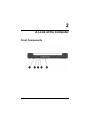
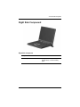
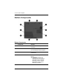
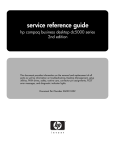
b
Hardware Guide
Compaq Evo Notebook N150 Series
Part Number: 233050-001
May 2001
This guide provides comprehensive information on setting up the
computer hardware and software, identifying computer
components, using the battery pack, connecting external devices,
and adding upgrades and accessories.
© 2001 Compaq Computer Corporation
Compaq, the Compaq logo, Armada, Deskpro Registered in U.S. Patent
and Trademark Office. Evo is a trademark of Compaq Information
Technologies Group, L.P. in the United States and other countries.
Microsoft, MS-DOS, Windows, Windows NT are trademarks of Microsoft
Corporation in the United States and other countries.
Intel, Pentium, Intel Inside, and Celeron are trademarks of Intel
Corporation in the United States and other countries.
All other product names mentioned herein may be trademarks of their
respective companies.
Compaq shall not be liable for technical or editorial errors or omissions
contained herein. The information in this document is provided “as is”
without warranty of any kind and is subject to change without notice. The
warranties for Compaq products are set forth in the express limited
warranty statements accompanying such products. Nothing herein should
be construed as constituting an additional warranty.
Hardware Guide
First Edition (May 2001)
Part Number: 233050-001
Contents
1 Hardware and Software Setup
Setting Up the Hardware . . . . . . . . . . . . . . . . . . . . . . . . .
Setting Up the Software . . . . . . . . . . . . . . . . . . . . . . . . . .
Completing Initial Setup . . . . . . . . . . . . . . . . . . . . . .
Installing Optional Applications . . . . . . . . . . . . . . . .
After Software Setup . . . . . . . . . . . . . . . . . . . . . . . . . . . .
1–1
1–6
1–6
1–7
1–7
2 A Look at the Computer
Front Components . . . . . . . . . . . . . . . . . . . . . . . . . . . . . . 2–1
Top Components . . . . . . . . . . . . . . . . . . . . . . . . . . . . . . . 2–3
Right Side Component . . . . . . . . . . . . . . . . . . . . . . . . . . . 2–7
Left Side Components . . . . . . . . . . . . . . . . . . . . . . . . . . . 2–8
Rear Panel Components . . . . . . . . . . . . . . . . . . . . . . . . . 2–10
Bottom Components. . . . . . . . . . . . . . . . . . . . . . . . . . . . 2–12
Additional Standard Components . . . . . . . . . . . . . . . . . 2–14
3 Keyboard and Pointing Devices
Using the TouchPad . . . . . . . . . . . . . . . . . . . . . . . . . . . . .
Using Hotkeys . . . . . . . . . . . . . . . . . . . . . . . . . . . . . . . . .
Hotkeys . . . . . . . . . . . . . . . . . . . . . . . . . . . . . . . . . . .
Using the Embedded Numeric Keypad . . . . . . . . . . . . . .
Enabling the Numeric Keypad . . . . . . . . . . . . . . . . .
Disabling the Numeric Keypad . . . . . . . . . . . . . . . . .
Converting the Numeric Keypad
Keys to Standard Keys . . . . . . . . . . . . . . . . . . . . . . .
Using the Easy Access Buttons . . . . . . . . . . . . . . . . . . . .
Hardware Guide
3–1
3–2
3–3
3–5
3–5
3–6
3–6
3–6
iii
Contents
4 Battery Packs
Charging Battery Packs . . . . . . . . . . . . . . . . . . . . . . . . . .
Using a New Battery Pack . . . . . . . . . . . . . . . . . . . . . . . .
Replacing the Primary Battery Pack . . . . . . . . . . . . . . . .
Installing or Removing the Optional
Media Bay Battery Pack. . . . . . . . . . . . . . . . . . . . . . . . . .
Using the Battery Quick Charge Check . . . . . . . . . . . . . .
Calibrating the Battery . . . . . . . . . . . . . . . . . . . . . . . . . . .
Storing a Battery Pack . . . . . . . . . . . . . . . . . . . . . . . . . . .
Recycling a Used Battery Pack . . . . . . . . . . . . . . . . . . . .
4–1
4–2
4–2
4–4
4–6
4–6
4–8
4–8
5 Drives
Caring for Drives . . . . . . . . . . . . . . . . . . . . . . . . . . . . . . .
Removing and Inserting the Hard Drive . . . . . . . . . . . . .
Inserting or Removing a Media
Bay Drive . . . . . . . . . . . . . . . . . . . . . . . . . . . . . . . . . . . . .
Connecting the Optional
External Diskette Drive . . . . . . . . . . . . . . . . . . . . . . . . . .
Removing and Inserting Storage Media. . . . . . . . . . . . . .
Inserting and Removing a Diskette . . . . . . . . . . . . . .
Inserting a Disc into the CD or DVD Drive . . . . . . .
Viewing the CD . . . . . . . . . . . . . . . . . . . . . . . . . . . . .
Removing a Disc from the CD or DVD Drive . . . . .
Changing the Startup Sequence . . . . . . . . . . . . . . . . . . . .
5–1
5–2
5–3
5–4
5–5
5–5
5–6
5–7
5–7
5–8
6 Audio
Using Audio Features. . . . . . . . . . . . . . . . . . . . . . . . . . . .
Connecting to the Stereo Line-Out/Headphone Jack
Connecting to the Stereo Line-In Jack . . . . . . . . . . .
Adjusting Volume . . . . . . . . . . . . . . . . . . . . . . . . . . . . . .
6–1
6–2
6–3
6–3
7 External Device Connections
Connecting an External Keyboard or Pointing Device . . 7–1
Connecting an External Monitor . . . . . . . . . . . . . . . . . . . 7–2
Connecting a Serial Printer . . . . . . . . . . . . . . . . . . . . . . . 7–2
iv
Hardware Guide
Contents
Connecting a Parallel Printer . . . . . . . . . . . . . . . . . . . . . .
Connecting Infrared Equipment. . . . . . . . . . . . . . . . . . . .
Infrared Connection Guidelines. . . . . . . . . . . . . . . . .
Infrared Configuration Guidelines. . . . . . . . . . . . . . .
Enabling the Infrared Port . . . . . . . . . . . . . . . . . . . . .
Connecting USB Equipment . . . . . . . . . . . . . . . . . . . . . .
Connecting a Modem or NIC Cable. . . . . . . . . . . . . . . . .
Using the Security Slot. . . . . . . . . . . . . . . . . . . . . . . . . . .
7–3
7–3
7–4
7–5
7–5
7–6
7–6
7–8
8 Computer Upgrades and Add-Ons
Before Removing or Installing Components . . . . . . . . . . 8–1
Upgrading Memory . . . . . . . . . . . . . . . . . . . . . . . . . . . . . 8–2
Removing and Inserting a
Memory Expansion Board. . . . . . . . . . . . . . . . . . . . . 8–3
Adding and Using PC Cards . . . . . . . . . . . . . . . . . . . . . . 8–6
Configuring a PC Card . . . . . . . . . . . . . . . . . . . . . . . 8–6
Inserting a PC Card . . . . . . . . . . . . . . . . . . . . . . . . . . 8–7
Removing a PC Card . . . . . . . . . . . . . . . . . . . . . . . . . 8–8
Conserving Energy . . . . . . . . . . . . . . . . . . . . . . . . . . 8–8
Installing Additional Device Drivers. . . . . . . . . . . . . 8–9
Adding Wireless Devices. . . . . . . . . . . . . . . . . . . . . . . . . 8–9
Media Bay Devices . . . . . . . . . . . . . . . . . . . . . . . . . . . . 8–10
External Diskette Drive . . . . . . . . . . . . . . . . . . . . . . . . . 8–10
Battery Packs . . . . . . . . . . . . . . . . . . . . . . . . . . . . . . . . . 8–10
Upgrading the Hard Drive . . . . . . . . . . . . . . . . . . . . . . . 8–10
9 Specifications
Regulatory Agency Series Numbers . . . . . . . . . . . . . . . .
Computer Dimensions . . . . . . . . . . . . . . . . . . . . . . . . . . .
Operating Environment . . . . . . . . . . . . . . . . . . . . . . . . . .
Rated Input Power . . . . . . . . . . . . . . . . . . . . . . . . . . . . . .
Port and COM Port Settings. . . . . . . . . . . . . . . . . . . . . . .
Communications Specifications. . . . . . . . . . . . . . . . . . . .
Hardware Guide
9–1
9–2
9–2
9–3
9–3
9–4
v
Contents
10 Computer Utilities
Using the PhoenixBIOS Setup Utility . . . . . . . . . . . . . .
Power Management . . . . . . . . . . . . . . . . . . . . . . . . . . . .
Enabling Power Savings . . . . . . . . . . . . . . . . . . . . .
Timeout Settings . . . . . . . . . . . . . . . . . . . . . . . . . . .
Setting Standby . . . . . . . . . . . . . . . . . . . . . . . . . . . .
Hibernation. . . . . . . . . . . . . . . . . . . . . . . . . . . . . . . . . . .
Security . . . . . . . . . . . . . . . . . . . . . . . . . . . . . . . . . . . . .
10–1
10–1
10–2
10–2
10–2
10–3
10–3
Index
vi
Hardware Guide
1
Hardware and Software Setup
Setting Up the Hardware
1. Record the Product Key for your operating system. You will
need to enter or verify this number during software setup.
You may also need it to update or troubleshoot your operating
system. The Product Key is located on the Certificate of
Authenticity label on the bottom of the computer.
Locating the Product Key
Hardware Guide
1–1
Hardware and Software Setup
2. Locate the battery pack in the shipping box. If tape is
covering the battery contacts, remove it before installing the
battery pack.
3. Install the battery pack into the battery compartment.
a. Turn the computer bottom side up.
b. Insert the battery at a 45-degree angle into the
compartment 1, ensuring that the battery tabs are flush
with the front edge of the compartment.
c. Press down the battery pack until the release latch 2
clicks.
Installing the battery pack
4. Turn the computer top side up and place it on a flat surface
near an electrical outlet.
1–2
Hardware Guide
Hardware and Software Setup
Å Safety Notices guide on the
WARNING: This is a Class B digital device, pursuant to Part 15 of the
FCC Rules. For more Class B information, refer to the Regulatory and
Compaq Notebook Products Reference
Library CD, included with the computer. To reduce the risk of personal
injury, electric shock, fire, or damage to the equipment:
■ Do not disable the power cord grounding plug. It is an important
safety feature.
■ Plug the equipment into a grounded (earthed) electrical outlet
that is easily accessible at all times.
5. Connect the computer to external power.
Plug the AC Adapter cable into the power connector 1. Plug
the power cord into the AC Adapter 2 and into an electrical
outlet 3.
✎ Power cords and electrical outlets vary by country.
Connecting the AC Adapter and power cord
Hardware Guide
1–3
Hardware and Software Setup
6. Open the computer by sliding the display latch to the right 1
and raising the display 2.
Opening the computer
1–4
Hardware Guide
Hardware and Software Setup
7. Turn on the computer by pressing the power button 1.
Turning on the computer
When power is turned on:
■
The power/standby light 2 turns on.
■
The battery pack in the battery compartment begins to charge
and the battery light 3 turns on. The battery light:
■
❏
Remains on while the battery pack is charging.
❏
Turns off when the battery pack is fully charged.
You are prompted to begin software setup.
Hardware Guide
1–5
Hardware and Software Setup
Setting Up the Software
Completing Initial Setup
You can begin initial setup as soon as the computer is connected
to external power and the initial setup prompt is displayed on the
screen.
Before responding to the initial setup prompt and proceeding
through the online instructions, read the following caution and
other initial setup information:
Ä■
CAUTION: To prevent file corruption and ensure that the correct drivers
install during initial setup:
Do not unplug the computer from the electrical outlet.
■ Do not shut down the computer.
■ Do not remove or insert a drive.
■
Once you begin initial software setup, you must complete the
entire process. Setup time varies by computer configuration.
■
If you are prompted to select a language or operating system,
choose carefully.
■
1–6
❏
The languages and operating system that you do not
choose will be deleted from the system and cannot be
restored during initial setup.
❏
An operating system available during initial setup is
enhanced by Compaq. When an operating system is
deleted, the enhancements are also deleted.
During the setup process, you must accept the End User
License Agreement to continue. The Product Key referenced
on the License Agreement screen is on the Certificate of
Authenticity label on the bottom of the computer. You may
want to verify that the Product Key displayed on the screen is
the same as the number on the label.
Hardware Guide
Hardware and Software Setup
Installing Optional Applications
You can install third-party applications or preloaded Compaq
utilities at any time after initial setup is complete.
■
To install a third-party application, refer to the documentation
included with the application.
■
To install a preloaded Compaq utility, select the Setup
Compaq Software icon on the Desktop, then follow the
instructions on the screen.
If the icon does not display on the Desktop after initial setup
is complete, select Start > Run. On the command line, type:
C:\cpqapps\setup.exe preload /s
To view the descriptions and space requirements of preloaded
Compaq utilities without installing them, select the Setup
Compaq Software icon on the Desktop, then select Next. After
viewing the utility information, select Cancel.
After Software Setup
After the initial setup is complete, you may want to:
■
Calibrate the battery pack.
Although you can use a new battery pack that has been fully
charged to run the computer, the computer cannot accurately
report the amount of charge in the battery pack until the
battery pack has been calibrated. For calibration information
and instructions, refer to the “Battery Packs” chapter in this
guide.
■
Read suggestions for creating a safe and comfortable work
environment.
Ergonomic and safety information about the computer is
provided in the Safety & Comfort Guide on the Notebook
Products Reference Library CD included with the computer.
Hardware Guide
1–7
Hardware and Software Setup
Å■
WARNING: To reduce the risk of personal injury, electric shock, fire, or
damage to the equipment:
Disconnect power from the equipment by unplugging the power
cord from the electrical outlet.
■ Do not place anything on power cords or cables. Arrange them
so that no one may accidentally step on or trip over them.
■ Do not pull on a cord or cable. When unplugging from the
electrical outlet, grasp the cord by the plug.
1–8
Hardware Guide
2
A Look at the Computer
Front Components
Hardware Guide
2–1
A Look at the Computer
Front Components
Component
Function
1
Stereo line-out/headphone
jack
Connects stereo speakers, headphones,
headset, or television audio.
2
Stereo line-in jack
Connects a CD player, turner, or tape
deck.
3
Power light
On: Power is turned on.
Blinking: Computer is in Standby.
The power light also blinks if a battery
pack that is the only available power
source reaches a low-battery condition.
4
Battery light
On: A battery pack is charging.
Blinking: A battery pack that is the only
available power source has reached a
low-battery condition.
5
Hard drive
Removable primary hard drive. Two
screws secure the drive to the computer.
2–2
Hardware Guide
A Look at the Computer
Top Components
Top Components
Component
Function
1
Power button
Turns on the computer.To turn off the
computer, use the operating system
Shut Down command.
2
Microphone
Inputs single-channel sound to the
computer; can be used whether the
computer is open or closed.
3
Easy Access Buttons
Four buttons that provide quick access
to the Internet. Refer to Chapter 3,
“Keyboard and Pointing Devices,” for
information about these buttons.
4
Stereo Speakers (2)
Produce Stereo Sound.
Hardware Guide
2–3
A Look at the Computer
Top Components
Component
Function
5
Windows application key
Displays the shortcut menu for the item
beneath the pointer.
6
TouchPad and TouchPad
buttons
Moves the cursor, selects and activates.
The right and left buttons function like
buttons on an external mouse.
7
Windows logo key
Displays the Windows Start menu.
2–4
Hardware Guide
A Look at the Computer
Top Component Lights
Component
Function
1
Drive light indicator
Turns on when the hard drive, CD, or
DVD is accessed.
2
Diskette drive light
Turns on when the diskette drive in the
Media Bay or the optional external
diskette drive is accessed.
3
Num lock light
On: Num lock is on and the embedded
numeric keypad is enabled.
4
Caps lock light
On: Caps lock is on.
Hardware Guide
2–5
A Look at the Computer
Top Component Lights
Component
Function
5
Scroll lock light
On: Scroll is on.
6
Power light
On: Power is turned on.
Blinking: Computer is in Standby. The
power light also blinks if a battery pack
that is the only available power source
reaches a low-battery condition.
7
Battery charge light
On: A battery is charging.
Blinking: A battery pack that is the only
available power source has reached a
low-battery condition.
2–6
Hardware Guide
A Look at the Computer
Right Side Component
Right Side Component
Component
Function
Media Bay
Accepts a CD-ROM, CD-RW, DVD,
diskette drive, or second battery
pack.
Hardware Guide
2–7
A Look at the Computer
Left Side Components
Left Side Components
Component
Function
1
Security slot
Attaches an optional security cable to
the computer.
2
Vent
Allows airflow to cool internal
components.
prevent damage,
Ä CAUTION:To
the system will shut down if a
severe overheating condition
occurs. To prevent loss of
information, do not block the
cooling vent. Avoid placing the
computer on a blanket, rug, or
other flexible surface that may
cover the vent area.
3
2–8
Air intake vent
Cools internal components.
Hardware Guide
A Look at the Computer
Left Side Components
Component
Function
4
RJ-11 jack (internal modem
models only)
Connects the modem cable to an
internal modem. A modem cable is
included with internal modem models.
5
USB connector
Connects USB devices.
6
PC Card slots (2)
Support a 32-bit (CardBus) or 16-bit
PC Card.
7
PC Card eject buttons
Eject a PC Card from the PC Card slot.
Hardware Guide
2–9
A Look at the Computer
Rear Panel Components
Rear Panel Components
Component
Function
1
Infrared port
Links to another IrDA-compliant device
for wireless communication.
2
Parallel connector
Connects a parallel device.
3
Serial connector
Connects a serial device.
4
Keyboard/mouse connector
Connects an external keyboard or
PS/2-compatible external mouse.
✎
5
2–10
RJ-45 jack (network models
only)
To connect a keyboard and a
mouse at the same time, use
an optional Y-adapter.
Connects the network cable. A network
cable is not included with the computer.
Hardware Guide
A Look at the Computer
Rear Panel Components (Continued)
Component
Function
6
USB connector
Connects USB devices.
7
External monitor connector
Connects an external monitor or
microportable projector.
8
DC power jack
Connects any one of the following:
Hardware Guide
■
AC Adapter
■
Optional Automobile Power
Adapter/Charger
■
Optional Aircraft Power Adapter
2–11
A Look at the Computer
Bottom Components
Bottom Components
Component
Function
1
Media Bay release latch
Releases the media bay device from the
connector.
2
Serial number
Identifies the computer; needed when
you call Compaq customer support.
3
Fan
Provides airflow to cool internal
components.
4
Reset button
Manually resets the system if a failure
occurs.
WARNING: Resetting the
computer will cause unsaved
information to be lost. Before
performing a reset, close all
applications and shut down
Windows, if possible.
Å
2–12
Hardware Guide
A Look at the Computer
Bottom Components (Continued)
Component
Function
5
Memory expansion
compartment cover
Covers the memory expansion
compartment that contains a memory
expansion slot for one memory
expansion board.
6
Hard drive
Removable primary hard drive. Two
screws secure the drive into the
computer.
7
Battery security latch
Secures the battery pack in the battery
compartment.
8
Battery release latch
Releases the battery pack from the
battery compartment.
9
Battery compartment
Holds the primary battery pack.
-
Media Bay
Supports a CD-ROM, CD-RW, DVD,
diskette drive or second battery pack.
Hardware Guide
2–13
A Look at the Computer
Additional Standard Components
The components included with the computer vary by geographic
region and the computer hardware configuration ordered.
The following illustration and table identify the standard
components included with most computer models.
components ship inside computer compartments identified
✎ Some
in previous sections and are not included in this illustration.
Additional Standard Components
Component
Function
1
Battery pack
Allows the computer to operate on
battery power. Installs in the battery
compartment on the bottom side of the
computer.
2
Power cord
Connects the AC Adapter to an AC
electrical outlet.
3
AC Adapter
Converts AC power to DC power.
2–14
Hardware Guide
A Look at the Computer
Additional Standard Components (Continued)
Component
Function
4
QuickRestore kit
Contains the software preinstalled on
the computer.
5
Notebook Products
Reference Library CD-ROM
Contains the following guides:
■
Hardware Guide
■
Modem and Networking
■
Modem Commands
■
Maintenance, Shipping and Travel
■
Troubleshooting
■
Regulatory and Safety Notices
■
Safety & Comfort Guide
6
Modem cable (internal
modem models only)
Connects the modem to an RJ-11
telephone jack or to a country-specific
adapter.
7
Country-specific modem
adapter (included with
internal modem models by
region as required)
Adapts the modem cable to a non-RJ-11
telephone jack.
Hardware Guide
2–15
3
Keyboard and Pointing Devices
Using the TouchPad
The TouchPad performs the same basic operations as a mouse. It
functions with any software that supports a Microsoft-compatible
mouse. The TouchPad 1 includes left 2 and right 3 TouchPad
buttons for function or application selection. To operate the
TouchPad, slide your finger across its surface in the direction you
want to move the cursor and click the left or right button to make
a selection or complete an activity.
Identifying TouchPad components
Hardware Guide
3–1
Keyboard and Pointing Devices
Using Hotkeys
Hotkey Quick Reference
Function
Hotkey
Return to Original
State
Switch display and image
(switching between the
display and external
monitor)
Fn+F3
Fn+F3
Standby
Fn+F4
Press the power button
Adjusts screen brightness
Fn+F7 (decrease)
Fn+F8 (increase)
Fn+F8 (increase)
Fn+F7 (decrease)
3–2
Hardware Guide
Keyboard and Pointing Devices
Hotkeys
Hotkeys are preset combinations of the Fn key 1 and another key
that access or execute frequently used system functions. The
icons on the function keys F3 to F8 2 represent these functions.
Hotkeys can be used at anytime and from within any application.
Identifying the Hotkeys
Switch Display and Image (Fn+F3)
■
Microsoft Windows Millennium Edition (Me) or
Windows 98 with Extended Desktop disabled—Toggle
Fn+F3 to switch the image among
❏
Computer display
❏
External display
❏
Simultaneous display (computer and external displays)
The external monitor can be connected through the external
monitor connector.
Hardware Guide
3–3
Keyboard and Pointing Devices
■
Microsoft Windows Me or Windows 98 with Extended
Desktop enabled—Press Fn+F3 to turn off an external
display connected to the external monitor connector and to
disable Extended Desktop.
■
Microsoft Windows 2000 Professional—Toggle Fn+F3 to
switch the image among
❏
Computer display
❏
External display
❏
Simultaneous display (computer and external displays)
The external monitor can be connected through the external
monitor connector.
Initiating Standby (Fn+F4)
Press Fn+F4 keys to manually put the computer in Standby. The
computer will automatically go into Hibernation after one hour of
Standby. To wake the computer, press the power button.
Adjust Screen Brightness (Fn+F7 and Fn+F8)
Press Fn+F7 to decrease the display screen brightness. To increase
the screen brightness, press Fn+F8.
3–4
Hardware Guide
Keyboard and Pointing Devices
Using the Embedded Numeric Keypad
The embedded numeric keypad consists of a cluster of 15 keys 1.
The character in the upper right corner of each of the keys
indicates the keypad function of that key.
The standard keyboard functions of the keys in the keypad are
disabled when the keypad is enabled.
Enabling the Numeric Keypad
To enable the keypad, press num lk 2. The num lock light 3 turns
on when the keypad is enabled.
keypad cannot be enabled while an optional external
✎ The
keyboard or numeric keypad is connected to the computer.
Identifying the embedded numeric keypad
Hardware Guide
3–5
Keyboard and Pointing Devices
Disabling the Numeric Keypad
To disable the keypad and return the keys to their standard
keyboard functions, press num lk.
Converting the Numeric Keypad
Keys to Standard Keys
To use the keypad keys temporarily as standard keys while the
keypad is enabled:
■
Press and hold Fn to type in lowercase.
■
Press and hold Fn+shift to type in uppercase.
When the Fn key is released, the keypad function returns.
Using the Easy Access Buttons
The Easy Access Buttons software, preinstalled on the computer,
lets you program the Easy Access buttons on the computer
keyboard to access any Internet addresses or to open any software
application or data file on your hard drive. Each of the four Easy
Access buttons is identified by an icon.
You can use the Easy Access Buttons software to:
■
Create and assign button schemes, which are a collection of
button assignments that you define and that are unique to
your Windows user profile.
■
Change a button name or assignment within a scheme.
■
Delete or add button schemes.
For procedures on programming the Easy Access buttons, refer to
the online help file. Select Start > Settings > Control Panel > Easy
Access Keyboard icon. From the Easy Access Buttons window,
select Help.
3–6
Hardware Guide
Keyboard and Pointing Devices
Identifying the Easy Access buttons
Hardware Guide
3–7
4
Battery Packs
Charging Battery Packs
The computer supports up to two battery packs: a primary battery
pack located in the battery compartment and an optional battery
pack in the Media Bay.
When both battery packs are used, the system charge and
discharge in a preset sequence:
■
Charge sequence:
1—Primary battery pack
2—Optional Media Bay battery pack
■
Discharge sequence:
1—Optional Media Bay battery pack
2—Primary battery pack
To charge the primary battery pack or optional Media Bay battery
pack, install the battery and connect the computer to AC power.
Leave the computer plugged into the electrical outlet until the
Battery Charging light is green. This ensures that the battery is
fully charged.
Hardware Guide
4–1
Battery Packs
Using a New Battery Pack
Charge the installed battery pack while connected to an external
power source.
A new battery pack should be fully charged before it is used for
the first time. The battery pack will work without being fully
charged, but the battery gauge will not show an accurate charge
until the battery pack receives its first full charge.
Replacing the Primary Battery Pack
You can resolve a low-battery condition by replacing a discharged
battery pack.
Ä
CAUTION: If you are removing a battery pack that is the only power
source available to the system while the computer is on, connect
the computer to another power source before removing the battery
pack. Failure to do so will result in loss of information. If the
computer is on and connected to more than one power source, you
can remove a battery pack.
1. If the battery pack in the battery compartment is the only
power source, connect to the computer to an external power
source such as the AC adapter.
2. Close the display and turn the computer bottom side up.
3. Slide the battery security latch to the unlock icon position 1.
4. To remove the battery pack, slide and hold the battery release
latch 2 to the right. The battery will disconnect.
5. Use the notch to lift the battery pack from the
compartment 3.
4–2
Hardware Guide
Battery Packs
Removing the battery pack
Hardware Guide
4–3
Battery Packs
6. To insert the new fully charged battery pack, angle the battery
pack into the compartment at a 45-degree angle so that the
battery tabs are aligned with the tabs inside the compartment
1. Press down on the battery pack until it is fully seated and
the battery release latch clicks 2.
7. Slide the battery security latch to the lock icon position 3.
Inserting the battery pack
8. Turn the computer top side up, remove the external power
source, open the display, and press the power button to
resume operation.
Installing or Removing the Optional
Media Bay Battery Pack
The Media Bay supports a second battery pack.
1. If running Windows 98 or Windows Me, save your work and
shut down the computer.
4–4
Hardware Guide
Battery Packs
If running Windows 2000, select the unplug or eject hardware
icon on the Windows system tray in the lower right corner of
the screen. A message will display when it is safe to remove
the device. Select okay at the message prompt.
2. Close the display and turn the computer bottom side up.
3. Slide and hold the Media Bay release latch in the direction of
the arrow on the latch 1.
4. Pull the device from the Media Bay 2.
5. Slide the new battery pack into the Media Bay until it clicks
into place.
6. Turn the computer top side up and open the display. If
running Windows 98 or Windows Me, turn on the computer.
7. To remove the battery pack, repeat the steps above.
Removing a Media Bay device
Hardware Guide
4–5
Battery Packs
Using the Battery Quick Charge Check
If your battery pack has a battery quick check feature, you can
monitor the charge in the battery pack when the battery pack is
not in the computer.
To display the percent of a full charge remaining in a battery
pack, press the button 1on the battery pack.
Each charge level light 2represents 20 percent of a full charge.
For example, when all lights are on, the battery pack is fully
charged.
Using the quick check feature
Calibrating the Battery
If the battery gauge becomes inaccurate, you must recalibrate the
battery pack. Recalibrating the battery means recharging the
battery to its maximum capacity and resetting the battery gauge to
accurately display the level of charge.
1. Plug in the AC adapter.
4–6
Hardware Guide
Battery Packs
a. Turn on or restart the computer. Press F10 during system
startup to run the PhoenixBIOS Setup Utility (PSU).
From the Security menu in PSU, enable “Battery
Calibration.” Save your setting and select exit from PSU.
b. Restart the computer and allow the battery pack to charge
until the battery charge light turns off. After the battery
light or the icon turns off, unplug the AC Adapter.
Steps 2 through 4 prevent the computer from entering Standby.
Follow these steps to drain the battery pack faster.
2. On the Windows taskbar, select Start > Settings > Control
Panel.
3. Select the Power Management icon > Power Schemes tab.
4. From the Running on Batteries column:
a. In the Turn Off Monitor, select Never.
b. In the Turn Off Hard Disk, select Never.
c. In the System Standby, select Never.
5. Select OK to close the Power Management Properties box.
Management functions are now disabled. If you want to
✎ Power
use the computer during calibration, save your information often
to prevent loss.
6. Let the battery pack drain until the computer reaches
Hibernation and turns off.
7. Plug in the AC adapter. Restart the computer.
8. Return to the Power Management Properties dialog box
under Control Panel and reenter the Power Savings settings to
the desired level.
9. Allow the battery pack to fully charge.
The battery is now calibrated.
Hardware Guide
4–7
Battery Packs
Storing a Battery Pack
If a computer will be unused and unplugged for more than two
weeks, remove and store the battery pack.
Ä
CAUTION: To prevent damage to a battery pack, do not expose it
to high temperatures for extended periods of time.
To prolong the charge of a stored battery pack, place it in a cool,
dry place. High temperatures cause a battery pack to lose its
charge more quickly, thus reducing battery life.
The recommended storage temperature range is from 32°F to
86°F (0°C to 30°C).
Recycling a Used Battery Pack
To determine if the battery pack recycling program is available in
your geographical region, refer to the Regulatory and Safety
Notices guide on the Notebook Products Reference Library CD. If
your region is not covered, refer to the Worldwide Telephone
Numbers guide included with the computer to contact your
Compaq authorized dealer, reseller, or service provider.
4–8
Hardware Guide
5
Drives
The computer supports the following drives that allow you to
store and access data:
■
Removable primary hard drive
■
One of the following in the Media Bay:
■
❏
CD drive
❏
DVD drive
❏
Diskette drive
Optional external diskette drive
Caring for Drives
To avoid unexpected loss of information caused by virus or
accidents, regularly back up the information on a hard drive.
Refer to the Regulatory and Safety Notices guide on the Notebook
Products Reference Library CD for FDA regulations on
laser-based drives and to the Maintenance, Travel, and Shipping
guide on the CD for information on caring for the hard drive.
Hardware Guide
5–1
Drives
Removing and Inserting the Hard Drive
Ä
CAUTION: To prevent damage to the computer and hard drive and
loss of information, ensure that you are discharged of static
electricity before handling a drive. Shut down the computer before
removing the hard drive from the hard drive bay. Do not remove the
hard drive while the computer is on, in Standby, or in Hibernation. If
you are not sure whether the computer is in Hibernation, turn the
computer on, then shut it down. If the computer is running a retail
version of a Windows operating system, shut down the computer
before removing any drive.
1. Save your work.
2. Shut down the computer and close the display.
3. Turn the computer bottom side up.
4. Remove the #1 Phillips screws securing the drive.
5. Firmly grasp the hard drive bezel and slide the drive from the
connector.
6. Place the removed drive in an electrostatic safe container.
Removing the hard drive
5–2
Hardware Guide
Drives
7. To insert a hard drive, slide the hard drive into the bay until it
is firmly seated in the connector and the bezel is flush with
the computer.
8. Reinstall the screws securing the hard drive.
9. Turn the computer top side up, open the display, and press the
power button to resume operation.
Inserting or Removing a Media
Bay Drive
The Media Bay supports a diskette drive, CD-ROM, CD-RW, or
DVD drive. When swapping or inserting a drive, use the
following steps.
1. If running Windows 98 or Windows Me, save your work and
shut down the computer.
If running Windows 2000, select the unplug or eject hardware
icon on the Windows system tray in the lower right corner of
the screen. A message will display when it is safe to remove
the drive. Select okay at the message prompt.
2. Close the display and turn the computer bottom side up.
3. Slide and hold the Media Bay release latch in the direction of
the arrow on the latch 1.
4. Pull the device from the Media Bay 2.
Hardware Guide
5–3
Drives
Removing a Media Bay drive
5. Slide the new drive into the Media Bay until it clicks into
place.
6. Turn the computer top side up and open the display. If
running Windows 98 or Windows Me, turn on the computer.
7. To remove the drive, repeat the steps above.
Connecting the Optional
External Diskette Drive
computer supports only one diskette drive at a time. If a
✎ The
diskette drive is used in the Media Bay, do not connect an external
diskette drive to the computer.
1. If the diskette drive and its drive bay are not assembled,
attach the two pieces by sliding the drive into the drive bay.
2. Attach the drive cable to the parallel port on the rear of the
computer.
5–4
Hardware Guide
Drives
Connecting the external diskette drive
3. To disconnect the drive, remove the diskette, if installed, from
the drive.
4. Unscrew the drive cable from the parallel port on the rear of
the computer.
Removing and Inserting Storage Media
Inserting and Removing a Diskette
To insert a diskette into the diskette drive, hold the diskette with
the label facing up and the arrow on the diskette pointing toward
the drive and gently push the diskette into the drive.
To remove a diskette, press the eject button on the diskette drive.
Hardware Guide
5–5
Drives
Inserting a Disc into the CD or DVD Drive
1. Turn on the computer.
2. Press the eject button on the front panel of the media tray to
open it.
Opening the media tray
3. Slowly pull out the tray.
4. Press the disc onto the tray spindle. Handle the disc by the
edges, not the flat surfaces.
5. Close the media tray.
The light on the drive turns on while the disc table of contents is
being read. The light turns off when the drive is ready to receive
commands.
5–6
Hardware Guide
Drives
Viewing the CD
When autorun is enabled, the CD contents will be displayed on
the screen.
If autorun is not enabled:
1. Click Start > Run, then type:
X:\program\autorun.exe
(where X = your CD drive designation)
2. Select the OK button.
Removing a Disc from the CD or DVD Drive
1. Turn on the computer.
2. Press the eject button on the front panel of the media tray to
open it.
3. Slowly pull out the tray until it is fully extended.
4. Remove the disc from the tray. Handle it by the edges, not the
flat surfaces.
5. Place the disc in its protective case.
6. Close the media tray.
Hardware Guide
5–7
Drives
Changing the Startup Sequence
The computer can start up from most bootable media or devices.
A bootable medium or device contains files needed by the
computer to start up and operate properly.
When more than one bootable medium or device is in the system,
the computer selects the medium or device to start from by
searching sequenced locations. The default startup sequence for
this computer is first the diskette drive, second the hard drive,
third the CD in the Media Bay, and fourth the internal NIC in the
computer.
You can change the sequence in which the computer searches for
a startup medium or device by selecting the Boot Device menu in
the PhoenixBIOS Setup Utility (PSU). To run PSU, press F10
during system startup.
5–8
Hardware Guide
6
Audio
Using Audio Features
The computer provides the following external audio features,
which are described in the following “Audio Components” table.
Identifying audio features
Hardware Guide
6–1
Audio
Audio Components
Component
Function
1
Microphone
Supports audio input when the display is
open and has a standard sensitivity of
–50dB.
2
Stereo speakers
Provide audio playback of multimedia
applications.
3
Stereo line-in jack
Supports a single line sound channel
(monaural) microphone with a 3.5-mm plug.
4
Stereo
line-out/headphone jack
Provides input from an external stereo
player such as a CD player, stereo turner, or
tape deck.
Connecting to the Stereo Line-Out/Headphone
Jack
When connecting a device to the stereo line-out jack:
■
Use only a 3.5-mm stereo plug.
■
Use 32-ohm headphones and at least 8-ohm external speakers
for best sound quality.
The stereo line-out jack disables the computer speaker when an
external audio device is plugged into the jack.
Å
WARNING: To reduce the risk of personal injury, turn down the
volume control before putting on headphones.
Ä
CAUTION: To prevent possible damage to an external device, do
not plug a single line sound channel (monaural) connector into the
stereo speaker/headphone jack.
6–2
Hardware Guide
Audio
Connecting to the Stereo Line-In Jack
When connecting an external stereo player, such as a CD player,
stereo tuner, or tape deck to the line-in jack:
■
Input device must have a 3.5-mm stereo plug.
■
Line input levels of 4.25 volts to 9.5 volts must be supplied,
which meet the line output specifications of most stereo
players.
Adjusting Volume
To increase, decrease, or mute the system volume, use the
Windows volume control window; double-click the volume icon
on the taskbar, then make your adjustment.
✎ Volume can also be adjusted within some applications.
Hardware Guide
6–3
7
External Device Connections
External devices can be physically connected to the computer. In
addition, some computer models can provide connections
between infrared equipped devices. Refer to “A Look at the
Computer” section in this guide to locate the connectors on your
computer. This section provides procedures for connecting
external devices to the computer.
Connecting an External Keyboard or
Pointing Device
The keyboard and external pointing devices need software device
drivers to operate. The necessary drivers are provided by the
manufacturer or may be preinstalled with the operating system.
To connect an external keyboard or external PS/2 mouse to the
computer, connect the cable to the keyboard/mouse connector on
the computer.
To connect both an external keyboard and PS/2 external mouse or
external trackball to the single keyboard/mouse connector,
purchase a Y-adapter. The adapter connects the single
keyboard/mouse connector into two connectors.
Hardware Guide
7–1
External Device Connections
Connecting an External Monitor
Ä
CAUTION: To prevent damage to the computer, turn off the monitor
before connecting it to the computer or disconnecting it from the
computer. To prevent damage to the computer display, do not place
an external monitor or any other object on top of the computer
when the computer is closed.
To connect an external VGA monitor:
1. Turn off the monitor.
2. Plug the monitor signal cable into the external monitor
connector on the rear panel of the computer.
3. Plug the monitor power cord into a properly grounded
electrical outlet.
4. Turn on the monitor.
5. To ensure that the computer recognizes your monitor type,
refer to the operating system documentation and select the
appropriate manufacturer and model.
If the external monitor does not immediately show an image, try
using the Fn+F3 hotkeys. Refer to the documentation included
with the monitor for additional setup information.
Connecting a Serial Printer
1. Turn off the printer.
2. Plug the printer end of the printer signal cable into the printer.
3. Connect the serial printer signal cable to the serial connector
on the rear panel of the computer.
4. Plug the printer power cord into a properly grounded
electrical outlet.
5. Turn on the printer.
7–2
Hardware Guide
External Device Connections
The Microsoft Windows operating system should prompt you to
set up the printer before printing for the first time. If setup fails,
consult the printer documentation for information and
instructions on device driver.
Connecting a Parallel Printer
1. Turn off the printer.
2. Plug the printer end of the printer signal cable into the printer.
3. Connect the signal cable to the parallel connector on the rear
panel of the computer.
4. Plug the printer power cord into a properly grounded
electrical outlet.
5. Turn on the printer.
The Microsoft Windows operating system should prompt you to
set up the printer before printing for the first time. If setup fails,
consult the printer documentation for device driver configuration
information and instructions.
Connecting Infrared Equipment
The infrared port allows communication between the computer
and another infrared-equipped device by producing an invisible
beam of infrared light between the devices. Infrared performance
varies depending on equipment, distance between infrared
devices, and applications being used. The infrared port is
IrDA-compliant and supports both low-speed connections up to
115 kilobits per second (Kbps) and high-speed connections up to
4 megabits per second (Mbps).
Operating system support for infrared communication is currently
available with Microsoft Windows 98 (Second Edition),
Windows Me, and Windows 2000 Professional.
Hardware Guide
7–3
External Device Connections
Communicating with infrared
Infrared Connection Guidelines
7–4
■
Be sure the infrared ports on both devices are turned on and
facing each other at a distance no greater than 1.5 feet (about
0.5 meter).
■
Avoid moving the infrared ports away from each other during
data transmission.
■
Avoid interference from remote control units, such as
wireless headphones or audio devices, pointed at the infrared
ports.
■
Avoid direct sunlight, fluorescent light, or flashing
incandescent light close to the infrared ports.
■
Keep the path between the infrared ports free of any objects
that might interfere with data transmission.
■
Do not point one of the ports more than 30 degrees (plus or
minus 15 degrees off the center line) away from the infrared
port of the device you are connecting with.
Hardware Guide
External Device Connections
Infrared Configuration Guidelines
■
■
The infrared port default settings are as follows:
❏
Port—COM3
❏
Address—1487-147F
❏
Interrupt request (IRQ)—9
If you use Direct Cable Connection and the utility prompts
you to choose a port for the infrared connection, you can
select Serial Cable on COM5 or, if the computer is running a
preinstalled Windows 98, Windows Me, or Windows 2000
Professional operating system, select Parallel Cable on LPT3.
Enabling the Infrared Port
The infrared port is enabled by default each time the computer
starts up.
■
When the infrared port is enabled, the infrared icon is
displayed on the taskbar and Infrared Monitor Search is
enabled by default.
■
While the Infrared Monitor Search is enabled:
■
❏
You can establish an infrared link.
❏
The system cannot initiate Standby. User-initiated
Standby is not affected.
When the Infrared Monitor Search is disabled:
❏
Power is conserved.
❏
You cannot establish an infrared link.
❏
The system can initiate Standby.
Hardware Guide
7–5
External Device Connections
Connecting USB Equipment
USB (Universal Serial Bus) is a hardware interface that can be
used to connect such low-speed external devices as a USB
keyboard, mouse, drive, printer, scanner, or hub to the computer.
USB hubs connect to a USB port on the computer and then to
other USB devices. Hubs support varying numbers of USB
devices and are used to increase the number of USB devices in
the system. Powered hubs must be connected to external power.
Unpowered hubs must be connected either to the USB port on the
computer or to a port on a powered hub.
A USB port on the computer supports USB devices only if the
computer is running an operating system that supports USB.
Windows 98, Windows Me, and Windows 2000 Professional
support USB.
Some USB devices may require additional support software,
which is usually included with the device. For more information
and software installation instructions, refer to the documentation
included with the device.
Connecting a Modem or NIC Cable
The RJ-11 jack and the RJ-45 jack allow computer models with
an internal modem, internal NIC (network interface card), or both
to connect to a networked interface. You will need to purchase the
modem and network cables if they are not provided with the
computer.
7–6
Hardware Guide
External Device Connections
Modem models will need an RJ-11 cable. To connect the cable:
1. Plug one end of the RJ-11 cable into the RJ-11 jack on the
computer. If the RJ-11 cable contains a noise suppression
circuit, which prevents interference with TV and radio
reception, orient the cable so that the noise suppression
circuitry is closest to the computer.
2. Plug the opposite end of the cable into a standard telephone
wall jack. Or, if applicable, plug the opposite end of the cable
into the phone plug adapter, which then plugs into the wall
jack. Some countries may require an adapter to connect the
modem to the telephone wall jack.
The NIC models will need an RJ-45 cable. To connect the cable:
1. Plug one end of the RJ-45 cable into the RJ-45 jack on the
computer.
2. Connect the other end of the cable into the network jack.
To find additional modem and NIC information, refer to the
following documents:
■
Modem and Networking guide on the Notebook Products
Reference Library CD for configuring the modem and
installing software.
■
Modem Commands on the Notebook Products Reference
Library CD for AT Commands, including dial modifiers and
instructions.
Hardware Guide
7–7
External Device Connections
Using the Security Slot
The security slot on the computer allows you to physically secure
the computer. To use the security slot:
1. Loop the cable around a secure object.
2. Insert the locking device 1 into the security slot 2.
3. Turn the locking device 3 clockwise 90 degrees.
To remove the device, turn the locking device counterclockwise
90 degrees and remove the device from the slot.
7–8
Hardware Guide
8
Computer Upgrades and Add-Ons
The computer supports several notebook accessories for you to
upgrade and add on to your system.
Armada notebook accessories, such as MultiBay options
✎ Several
and the Armada M Series external diskette drive, are not
compatible with this computer model.
To order accessories, visit the Compaq Web site at
http://www.compaq.com or refer to the Worldwide Telephone
Numbers guide that came with your computer to contact a
Compaq authorized dealer, reseller, or service provider.
Before Removing or Installing
Components
Ä
CAUTION: Electrostatic discharge (ESD) can damage electronic
components. Before beginning any procedure, ensure that you are
discharged of static electricity by touching a grounded metal object.
For more information, refer to the Regulatory and Safety Notices
guide.
Å
WARNING: The procedures provided in this section are the only
user-accessible internal compartments on the computer. All other
areas that require a tool to access should be opened only by a
Compaq authorized service provider.
Hardware Guide
8–1
Computer Upgrades and Add-Ons
1. Shut down the computer.
2. Disconnect all external devices connected to the computer.
3. Disconnect the AC Adapter and remove the battery pack from
the computer.
4. Use a #1 Phillips screwdriver to remove screws. As you
remove screws from the computer, place them away from the
work area to prevent loss.
Upgrading Memory
You can increase RAM (random access memory) with an optional
memory expansion board or PC Cards.
To view the amount of RAM in the system:
■
Windows Me and Windows 98—Select Start > Settings >
Control Panel > Compaq Diagnostics.
■
Windows 2000—Select Start > Programs > Administrative
Tools > Compaq Diagnostics.
When RAM increases, the hard drive space reserved for the
hibernation file also increases. Windows 98 manages this
increase. If the computer is running Windows 2000 and you
experience problems with Hibernation after increasing RAM,
verify that your hard drive has enough free space for the larger
hibernation file.
■
■
8–2
To view the amount of space required by the hibernation file:
❏
Windows Me and Windows 98—Select Start >
Settings > Control Panel > Power > Hibernation tab.
❏
In Windows 2000—Select Start > Settings >
Control Panel > Compaq Power > Hibernation tab.
To view the amount of free space on your hard drive, select
My Computer. Right-click your hard drive, select Properties.
Hardware Guide
Computer Upgrades and Add-Ons
Removing and Inserting a
Memory Expansion Board
Å
WARNING: Failure to unplug the power cord and remove the
battery pack before installing a memory expansion board can
damage the equipment and expose you to the risk of electrical
shock.
1. Turn the computer bottom side up and remove the screws
securing the memory cover.
Removing the memory cover
Hardware Guide
8–3
Computer Upgrades and Add-Ons
2. To remove a memory board, pull away the plastic retention
clips on each side of the memory expansion board 1. The
memory expansion board tilts upward.
3. Lift the edge of the memory expansion board and slide it
gently out of the memory expansion slot at a 45-degree
angle 2.
Removing a memory expansion board
4. Place the removed memory expansion board in an
electrostatic-safe container.
8–4
Hardware Guide
Computer Upgrades and Add-Ons
5. To add a memory expansion board, insert it into the empty
memory expansion slot at a 45-degree angle 1. Then slide it
gently into place until it is seated while tilted.
expansion boards supported by the computer are keyed
✎ Memory
(notched) to ensure correct positioning.
6. Push the memory expansion board down until the plastic
retention clips 2 snap into place.
Inserting a memory expansion board
7. Replace the memory cover and reinstall the screws.
Ä■
CAUTION: If the newly installed memory does not work correctly:
Reseat the memory module.
■ Contact the memory module manufacturer if you suspect a
faulty memory module.
Hardware Guide
8–5
Computer Upgrades and Add-Ons
Adding and Using PC Cards
A PC Card is a credit card–sized accessory designed to conform
to the standard specifications of the Personal Computer Memory
Card International Association (PCMCIA). The computer
supports two Type II PC Cards and both 32-bit CardBus and
16-bit PC Cards.
PC Cards are classified as Type I, Type II, and Type III. The three
types are about the same length and width but vary in thickness.
Configuring a PC Card
Ä
CAUTION: If you install software or enablers provided by a PC Card
manufacturer, you may not be able to use other PC Cards. If you are
instructed by the documentation included with your PC Card to install
device drivers:
■ Install only the device drivers for your operating system.
■ Do not install card services, socket services, or enablers.
In Windows 98, Windows Me, and Windows 2000 Professional,
the operating system configures plug and play PC Cards.
8–6
Hardware Guide
Computer Upgrades and Add-Ons
Inserting a PC Card
Ä
CAUTION: To prevent damage to the connectors, use minimal
pressure when inserting a PC Card into a PC Card slot.
1. Hold the PC Card label side up with the connector facing the
computer.
2. Gently push the card into the slot until the card is seated.
Inserting a PC Card
Hardware Guide
8–7
Computer Upgrades and Add-Ons
Removing a PC Card
Ä
CAUTION: Failure to remove a PC Card that extends beyond the
computer before transporting the computer may cause permanent
damage to the PC Card connectors.
In Windows 98, Windows Me, and Windows 2000 Professional,
follow these steps:
1. Prepare the system for the PC Card removal. If the computer
is on, click the command to stop the PC Card before you
remove it. To stop a PC Card, select the PC Card icon in the
taskbar, then select the PC Card you want to stop, then select
Stop Card. A message displays when the PC Card can be
safely removed.
Ä
CAUTION: If the computer is on and running Windows 98, failure to
stop a PC Card before removing it may result in loss of work or a
system lockup.
2. Remove the PC Card by pressing the eject button once to
extend the button. Press the button again to eject the card.
3. Gently grasp and pull out the card
Conserving Energy
When a PC Card is inserted in the computer, it draws power from
the system even when a PC Card is not in use. To conserve power,
select the command to stop PC Cards or remove PC Cards when
they are not in use.
8–8
Hardware Guide
Computer Upgrades and Add-Ons
Installing Additional Device Drivers
Device drivers are programs or data files containing information
needed to run a particular PC Card. Compaq preinstalls most of
the device drivers you need on the computer.
✎ To save available memory, some device drivers are not turned on.
Some types of PC Cards, such as network cards, Global
Positioning System (GPS) cards, SCSI cards, audio cards, and
multifunction cards, require an additional software device driver
to function properly. The device driver is provided by the
PC Card manufacturer and should be installed according to the
manufacturer instructions. Do not install other PC Card software
that is provided by the manufacturer, even if prompted to do so.
The other software may prevent the computer from working
properly with all of your PC Cards.
Adding Wireless Devices
The computer supports a Compaq wireless device, such as the
Mini PCI 802.11b or Bluetooth PC Card.
Consult an authorized Compaq dealer for information on using
wireless connectivity devices with your computer.
Hardware Guide
8–9
Computer Upgrades and Add-Ons
Media Bay Devices
The Media Bay supports one of the following devices: CD drive,
DVD drive, diskette drive, or a second battery pack. Refer to the
“Drives” section in this guide for instructions on installing or
swapping devices in the Media Bay.
External Diskette Drive
An external diskette drive can be connected to the parallel port on
the rear of the computer. To connect the external drive, refer to
the “Drives” section in this guide.
Battery Packs
A second battery pack can be used as a spare or to provide
additional battery power to the primary battery pack. Consult an
authorized Compaq dealer for information on additional or
replacement battery packs for your computer. Refer to the section
on “Battery Packs” in this guide or to the documentation included
with the battery pack for installation instructions.
Upgrading the Hard Drive
Depending on your computer model, the primary hard drive can
be upgraded to a larger capacity. Contact your authorized
Compaq dealer for optional hard drives available for your
computer. Refer to the “Drives” section in this guide for
instructions on removing and inserting the hard drive.
8–10
Hardware Guide
9
Specifications
This computer has been tested and found to comply with the
limits for a Class B digital device. Refer to the Regulatory and
Safety Notices guide on the Notebook Products Reference Library
CD for governmental agency information.
Regulatory Agency Series Numbers
Regulatory agencies worldwide use agency series numbers for
product identification. Each approved product displays the
assigned agency series number. To ensure continued safe and
reliable operation, use the computer only with the products listed
below.
Agency Series Numbers
Product
Agency Series Number
Computer
PP2110
Primary Battery Pack
PP2111
Media Bay Battery Pack
PP2112
AC Adapter
PPP0005N
Automobile Adapter
401043
Aircraft Adapter
386504
Modem
J07M040.00
Network Interface Card
U98M010 and U98M008
Hardware Guide
9–1
Specifications
Computer Dimensions
Dimensions
U.S.
Metric
Height
1.31 in
33.4 mm
Width
12.16 in
309 mm
Depth
9.76 in
248 mm
Operating Environment
Factor
U.S.
Metric
Operating
50° to 95°F
10° to 35°C
Nonoperating
–4° to 140°F
–20° to 60°C
Temperature
Relative humidity (noncondensing)
Operating
10 to 90%
10 to 90%
Nonoperating
5 to 95%
5 to 95%
Maximum altitude (unpressurized)
Operating
10,000 ft
3,048 m
Nonoperating
30,000 ft
9,144 m
9–2
Hardware Guide
Specifications
Rated Input Power
Input Power
Rating
Operating voltage
100-120/220-240 VAC RMS
Operating current
1.3/0.65 A RMS
Operating frequency range
50-60 Hz AC
When powered by a DC source
18.5V MAX
✎
This product is designed for IT power systems in Norway with
phase-to-phase voltage not exceeding 240 Vrms.
Port and COM Port Settings
Port
Port
Address
IRQ
Serial port
3F8h - 3FFh
4
USB connector
1440-145Fh
11
Parallel port
378 - 3FFh
7
Serial I/O connector
COM1
3F8h - 3FFh
4
Internal modem
COM 2
2F8h - 2FFh
3
Infrared
COM 3
1478h - 147Fh
9
Hardware Guide
DMA
3
1
9–3
Specifications
Communications
Communications Specifications
Temperatures
Operating
32° to 167°F (0° to 75°C)
Storage
-40° to 167°F (-40° to 75°C)
Relative Humidity (non-condensing
Operating
-10 to 90% (-10 to 90%)
Storage
-5 to 95%@102°F (-5 to 95%@ 39°C)
Interfaces
9–4
Communications connector
Standard RJ-11
telephone
connector
Standard RJ-45
network
connector
Telephone, central office network
Internal DAA
Network
10Mbps
Ethernet: IEEE
802.3 standard
10BaseT
100Mbps
Ethernet: IEEE
802.3u standard
100Base TX
Hardware Guide
Specifications
Communications Specifications
Temperatures
Power Requirements
+3.3 volts +/-5%, +3.3 vaux +/-5%,
+5 volts +/-5%
Specifications
Lucent Win Modem - Assy Type III,
V.90 WW; refer to specifications
225641-001
Lucent Win Modem plus Intel
PRO/100 P Mobile Combo Adapter
- Assy, V.90 WW MDM, NIC,
MPC13, refer to specification
218480-001
Hardware Guide
9–5
10
Computer Utilities
Utilities that are preinstalled on the computer include:
■
PhoenixBIOS Setup Utility—Allows you to modify or
restore factory default settings and configure the system
BIOS to diagnose and solve minor problems.
■
Power Management—Allows you to reduce your computer
power consumption.
■
Security—Allows you to set or remove your power-on
password.
Using the PhoenixBIOS Setup Utility
The PhoenixBIOS Setup Utility (PSU) is built into the system.
You can configure the system BIOS and modify or restore factory
default settings, such as date and time, types of disk drives, power
management, and password settings. To run PSU, press F10
during system startup. When the main screen displays, use the
keyboard and arrow keys to move around the menus and make
selections.
Power Management
The computer operating system provides power management
utilities that help you maintain and conserve power when the
computer is running on battery power.
To access power management options, select the power
application icon in the operating system’s Control Panel.
Hardware Guide
10–1
Computer Utilities
Enabling Power Savings
The Enable Power Savings feature in Power Management
controls all power management features. When set to disabled,
the power menu is automatically disabled. The default setting is
enabled.
Timeout Settings
You can set up timeout functions to power down computer
components by selecting the Power Schemes tab from the power
application in the operating system’s Control Panel. When a
component such as the monitor, hard drive, system, or video is
not in use, the component powers down to conserve power. The
time out interval can be set from one minute up to several hours.
The component will power up again when you access it or press
any key.
Setting Standby
Standby is initiated by pressing the Fn+F4 hotkeys or
automatically by the computer if it reaches your defined
percentage of battery pack power remaining. When Standby is
initiated, several subsystems will power off to conserve energy.
The system will wake up from Standby when the power button is
pressed.
Although the Standby mode maintains your information and
opens your file upon wake-up, you will lose any unsaved
information if you turn off the computer before ending Standby.
10–2
Hardware Guide
Computer Utilities
Hibernation
Hibernation is an energy-saving feature and safeguard that saves
information in RAM to a hibernation file on the hard drive, then
shuts down the computer. Hibernation is initiated by the computer
when the computer reaches your defined percentage of battery
pack power remaining. To wake the computer from Hibernation,
press the power button. When you resume work, your information
returns to the screen where you left off.
Security
You can set a power-on password that will secure the information
you store on the hard disk. When turning on the computer, the
password you set must be entered before you can access your
files.
To set a password:
1. Press the Power button to turn on the computer.
2. Press F10 when the Compaq logo is displayed on the screen.
This will invoke the PhoenixBIOS Setup Utility (PSU).
3. Using arrow keys, select the Security option from the menu
bar.
4. Move to select Set Supervisor Password and press enter.
5. Set your personal password and press enter. You must confirm
the password and press enter again.
6. Move to Password On Boot and press enter. Select enable and
press enter.
7. Use arrow keys to select Exit from the menu bar.
8. Make sure the Exit Saving Changes is selected, then press
enter.
9. Select Yes to save your changes and Exit.
Hardware Guide
10–3
Computer Utilities
The power-on password is now set. Every time you turn on the
computer, resume working from Hibernation mode, or access
PSU, you must enter this password.
To remove a password:
1. Access PSU by turning on the computer and pressing F10
when the Compaq logo displays on the screen.
2. Enter your current password and press enter.
3. Move to Password On Boot. Use the + or - key to select
disable and press enter.
4. Move to Set Supervisor Password. In the upper space, enter
your current password and press enter. In the spaces to enter
your new password and confirm new password, press enter.
Press enter again to Exit the screen.
5. Use the arrow keys to select Exit from the menu bar.
6. Make sure Exit Saving Changes is selected. Press enter, then
select Yes to save your changes and exit.
10–4
Hardware Guide
Index
3rd-party applications, installing
1–7
A
AC Adapter 2–11, 2–14
accessories, ordering 8–1
additional standard components.
See standard components,
additional
air intake vent 2–8
Aircraft Power Adapter 2–11
audio components
adjusting volume 6–3
microphone 6–1, 6–2
stereo line-in jack 6–1, 6–2
stereo line-out/headphone jack
6–1, 6–2
stereo speakers 6–1, 6–2
using features 6–1
Automobile Power
Adapter/Charger 2–11
B
battery calibration 1–7, 4–6
battery charge light 2–5, 2–6
battery charging 4–1
battery compartment 2–12, 2–13
battery light 2–1, 2–2
battery pack
calibrating 4–6
charging 4–1
Hardware Guide
charging sequence 4–1
installing 1–2
optional Media Bay 4–4
preventing damage to 4–8
quick check feature 4–6
recycling 4–8
replacement 8–10
replacing 4–2
storing 4–8
using new 4–2
battery release latch 2–12, 2–13
battery security latch 2–12, 2–13
bottom components
battery compartment 2–12,
2–13
battery release latch 2–12, 2–13
battery security latch 2–12,
2–13
fan 2–12
hard drive, removable primary
2–13
Media Bay 2–12, 2–13
Media Bay release latch 2–12
memory expansion
compartment cover 2–12,
2–13
removable primary hard drive
2–12
Reset button 2–12
Serial number 2–12
Index-1
Index
button schemes, creating/deleting
3–6
C
cable lock, attaching 7–8
calibrating the battery packs 1–7
Caps lock light 2–5
cautions
battery pack(s) 4–2, 4–8
electrical safety 5–2, 8–1
external monitor 7–2
file corruption 1–6
headphones 6–2
memory installation 8–5
PC Card software 8–6
PC Cards 8–7, 8–8
setup 1–6
shutdown due to overheating
2–8
CD or DVD drives
caring for 5–1
Media Bay 5–3
using 5–6
CDs
Notebook Products Reference
Library CD-ROM 2–15
QuickRestore kit 2–15
Certificate of Authenticity label
1–1
charging sequence of battery packs
4–1
COM port settings 9–3
Compaq utilities. See software
component installation or removal
8–1
Index-2
components, additional standard.
See standard components,
additional
computer
connecting 1–3
opening 1–4
turning on 1–5
computer dimensions 9–2
computer upgrades 8–1
configuration of PC Cards 8–6
connecting
AC power 1–3
computer 1–3
power cord 1–3
country-specific modem adapter
2–14, 2–15
D
DC power jack 2–10, 2–11
device drivers, installing 8–9
diskette drive
external 5–4
supported devices 8–10
using 5–5
diskette drive light 2–5
displays, switching, with hotkey
3–2, 3–4
docking alignment hole 2–10
drive light 2–5
drives
caring for 5–1
changing startup sequence 5–8
Media Bay 5–3
removing/inserting media 5–2,
5–5
upgrades 8–10
Hardware Guide
Index
DVD drives
caring for 5–2
Media Bay 5–3
using 5–6
E
Easy Access Buttons 3–6
Easy Access buttons 2–3
electrostatic discharge (ESD) 5–2,
8–1
embedded numeric keypad
converting to standard keys 3–6
disabling 3–6
enabling 3–5
energy, conserving 8–8
external devices, connecting 7–1
external diskette drive 5–4
external monitor connector 2–10,
2–11
F
fan 2–12
front components
battery light 2–1, 2–2
hard drive 2–1, 2–2
headphone jack 2–1, 2–2
power light 2–1, 2–2
stereo line-in jack 2–1, 2–2
stereo line-out jack 2–1, 2–2
H
hard drive 2–1, 2–2
hard drive, removable primary
2–13
hard drive/CD/DVD light 2–5
hard drives
removing/inserting 5–2
Hardware Guide
upgrades 8–10
Hardware Guide. See Notebook
Products Reference Library
CD-ROM 2–15
hardware setup 1–1
headphone jack 2–1, 2–2, 6–1
headphones
and risk of personal injury 6–2
connecting 6–2
Hibernation mode 10–3
hotkeys
Quick Reference 3–2
Standby 3–2
using on external keyboard 3–3
I
infrared equipment
configuration guidelines 7–5
connecting 7–3
connection guidelines 7–4
infrared port 2–10, 7–5
input power 9–3
K
keyboard
connecting external 7–1
Easy Access Buttons 3–6
embedded numeric keypad 3–6
hotkeys 3–2
TouchPad 3–1
keyboard connector 2–10
L
language setup 1–6
left side components
air intake vent 2–8
PC Card eject buttons 2–8, 2–9
Index-3
Index
PC Card slots 2–8, 2–9
RJ-11 jack (internal modem
models only) 2–8, 2–9
security slot 2–8
USB connector(s) 2–8, 2–9
vent(s) 2–8
lights, top component. See top
component lights
line-in jack, stereo 6–3
line-out jack, stereo 6–2
M
Maintenance, Shipping and Travel
guide. See Notebook Products
Reference Library CD-ROM
2–15
Media Bay
battery pack 4–4
identified 2–7, 2–13
removing/inserting drive 5–3
supported devices 8–10
Media Bay release latch 2–12
memory
amount in system 8–2
installation warning 8–3
upgrades 8–2
memory expansion board,
removing/inserting 8–3
memory expansion compartment
cover 2–12, 2–13
microphone 2–3, 6–1, 6–2
Microsoft logo key 2–4
modem
connecting 7–6
installing 8–6
Index-4
Modem and Networking guide. See
Notebook Products Reference
Library CD-ROM 2–15
modem cable (internal modem
models only) 2–14, 2–15
Modem Commands guide. See
Notebook Products Reference
Library CD-ROM 2–15
modem specifications 9–4
monitor connector, external 2–10,
2–11
monitor, connecting 7–2
mouse
connecting external 7–1
connector 2–10
N
NIC (network interface card)
connecting 7–6
installing 8–6
Notebook Products Reference
Library CD-ROM 2–14, 2–15
Num lock light 2–5
numeric keypad, embedded 3–5
O
operating environment 9–2
operating system setup 1–6
optional Media Bay
battery pack 4–4
options 8–1
P
parallel connector 2–10
parallel printer
connecting 7–3
password setting 10–3
Hardware Guide
Index
PC Card eject buttons 2–8, 2–9
PC Card slots 2–8, 2–9
PC Cards
adding/using 8–6
configuring 8–6
inserting 8–7
removing 8–8
stopping 8–8
PhoenixBIOS Setup Utility (PSU)
10–1
pointing device, connecting
external 7–1
port settings 9–3
power button 2–3
power cord 2–14
power light 2–1, 2–2, 2–5, 2–6
power management 10–1, 10–2
power-on password 10–3
printers, connecting 7–2, 7–3
Product Key 1–1, 1–6
Q
quick check feature for battery 4–6
QuickRestore kit 2–14, 2–15
R
RAM amount 8–2
rear panel components
DC power jack 2–10, 2–11
docking alignment hole 2–10
external monitor connector
2–10, 2–11
infrared port 2–10
keyboard/mouse connector
2–10
parallel connector 2–10
Hardware Guide
RJ-45 jack (network models
only) 2–10
serial connector 2–10
USB connectors 2–10, 2–11
regulatory agency series numbers
9–1
Regulatory and Safety Notices
guide. See Notebook Products
Reference Library CD-ROM
2–15
removable primary hard drive
2–12
Reset button 2–12
right side component
Media Bay 2–7
RJ-11 jack 2–8, 2–9, 7–6, 7–7
RJ-45 jack 2–10, 7–6, 7–7
S
Safety & Comfort Guide. See
Notebook Products Reference
Library CD-ROM 2–15
screen brightness, adjusting 3–2,
3–4
Scroll lock light 2–5, 2–6
security 10–3
security slot 2–8, 7–8
sequence for charging battery
packs 4–1
serial connector 2–10
Serial number 2–12
serial printer, connecting 7–2
setup
caution 1–6
hardware 1–1
language 1–6
Index-5
Index
operating system 1–6
software 1–6, 1–7
software
device drivers 8–9
Easy Access Buttons 3–6
Enable Power Savings 10–2
Hibernation 10–3
installing Compaq utilities 1–7
installing optional applications
1–7
PhoenixBIOS Setup Utility
(PSU) 10–1
power management 10–1
Power Schemes 10–2
security 10–3
Standby 10–2
speakers, stereo 2–3, 6–1, 6–2
specifications
computer dimensions 9–2
modem communications 9–4
operating environment 9–2
port/COM port settings 9–3
rated input power 9–3
regulatory agency 9–1
standard components, additional
AC Adapter 2–14
battery pack 2–14
country-specific modem
adapter 2–14, 2–15
modem cable 2–14, 2–15
Notebook Products Reference
Library CD-ROM 2–14, 2–15
power cord 2–14
QuickRestore kit 2–14, 2–15
Standby
Index-6
and removing battery pack
(caution) 4–2
hotkeys 3–2
initiating 3–4
preventing 4–7
Standby mode 10–2
startup drive order, changing 5–8
stereo line-in jack 2–1, 6–1, 6–3
stereo line-out jack 2–1, 2–2
stereo line-out/headphone jack
6–1, 6–2
stereo speakers 2–3, 6–1, 6–2
storage media
removing/inserting 5–5
storage media, removing/inserting
5–2
T
third-party applications, installing
1–7
timeout settings 10–2
top component lights
battery charge light 2–5, 2–6
Caps lock light 2–5
diskette drive light 2–5
drive light 2–5
Num lock light 2–5
power light 2–5, 2–6
Scroll lock light 2–5, 2–6
top components
Easy Access buttons 2–3
microphone 2–3
Microsoft logo key 2–4
power button 2–3
stereo speakers 2–3
Windows application key 2–4
Hardware Guide
Index
TouchPad 2–4, 3–1
TouchPad buttons 3–1
Troubleshooting guide. See
Notebook Products Reference
Library CD-ROM 2–15
U
upgrades
computer 8–1
memory 8–2
options 8–1
USB (Universal Serial Bus)
equipment, connecting 7–6
USB connector(s) 2–8, 2–9, 2–10,
2–11
utilities. See software
Hardware Guide
V
vent(s) 2–8
volume, adjusting 6–3
W
warnings
headphones 6–2
memory installation 8–3
power cord 1–3, 1–8
resetting the computer 2–12
user-accessible computer parts
8–1
Windows 2000/Me/98 hotkeys
3–3, 3–4
Windows application key 2–4
wireless devices, adding 8–9
Index-7