1
Operation/Reference Guide
Delta Series
Distributed Audio Controllers
DAS-D(I)0404 4 Source, 4 Zone Controller
DAS-D(I)0406 4 Source, 6 Zone Controller
Matrix Distributed Audio
L as t R e vi s ed: 7 /1 4 /20 0 8
AMX Limited Warranty and Disclaimer
All products returned to AMX require a Return Material Authorization (RMA) number. The RMA number is
obtained from the AMX RMA Department. The RMA number must be clearly marked on the outside of each
box. The RMA is valid for a 30-day period. After the 30-day period the RMA will be cancelled. Any shipments
received not consistent with the RMA, or after the RMA is cancelled, will be refused. AMX is not responsible
for products returned without a valid RMA number.
Warranty Repair Policy
•
AMX will repair any defect due to material or workmanship issues during the applicable warranty period at no cost to the AMX
Authorized Partner., provided that the AMX Authorized Partner is responsible for in-bound freight and AMX is responsible for
out-bound ground freight expenses.
•
The AMX Authorized Partner must contact AMX Technical Support to validate the failure before pursuing this service.
•
AMX will complete the repair and ship the product within five (5) business days after receipt of the product by AMX. The AMX
Authorized Partner will be notified if repair cannot be completed within five (5) business days.
•
Products repaired will carry a ninety (90) day warranty or the balance of the remaining warranty, whichever is greater.
•
Products that are returned and exhibit signs of damage or unauthorized use will be processed under the Non-Warranty Repair
Policy.
•
AMX will continue to provide Warranty Repair Services for products discontinued or replaced by a Product Discontinuance
Notice.
Non-Warranty Repair Policy
•
Products that do not qualify to be repaired under the Warranty Repair Policy due to age of the product or Condition of the product may be repaired utilizing this service.
•
The AMX Authorized Partner must contact AMX Technical Support to validate the failure before pursuing this service.
•
Non-warranty repair is a billable service.
•
Products repaired under this policy will carry a ninety (90) day warranty on material and labor.
•
AMX will notify the AMX Authorized Partner with the cost of repair, if cost is greater than the Standard Repair Fee, within five (5)
days of receipt.
•
The AMX Authorized Partner must provide a Purchase Order or credit card number within five (5) days of notification, or the
product will be returned to the AMX Authorized Partner.
•
The AMX Authorized Partner will be responsible for in-bound and out-bound freight expenses.
•
Products will be repaired within ten (10) business days after AMX Authorized Partner approval is obtained.
•
Non-repairable products will be returned to the AMX Authorized Partner with an explanation.
•
See AMX Non-Warranty Repair Price List for minimum and Standard Repair Fees and policies.
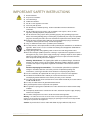
IMPORTANT SAFETY INSTRUCTIONS
IMPORTANT SAFETY INSTRUCTIONS
1.
2.
3.
4.
5.
6.
7.
8.
9.
10.
11.
12.
13.
14.
Read instructions.
Keep these instructions.
Heed all warnings.
Follow all instructions.
Do not use this apparatus near water.
Clean only with dry cloth.
Do not block any ventilation openings. Install in accordance with the manufacturer’s
instructions.
Do not install near any heat sources such as radiators, heat registers, stoves, or other
apparatus (including amplifiers) that produce heat.
Do not defeat the safety purpose of the grounding-type plug. The grounding plug has two
blades and a third grounding prong. The third prong is provided for your safety. If the provided
plug does not fit into your outlet, consult an electrician for replacement of the obsolete outlet.
Protect the power cord from being walked on or pinched particularly at plugs, convenience
receptacles, and the point where they exit from the apparatus.
Only use attachments/accessories specified by the manufacturer.
Use only with cart, stand, tripod, bracket, or table specified by the manufacturer, or sold with the
apparatus. When a cart is used, use caution when moving the cart/apparatus combination to
avoid injury from tip-over.
Unplug this apparatus during lightning storms or when unused for long periods of time.
Refer all servicing to qualified personnel. Servicing is required when the apparatus has been
damaged in any way, such as power supply cord or plug is damaged, liquid has been spilled or
objects have fallen into the apparatus, the apparatus has been exposed to rain or moisture,
does not operate normally, or has been dropped.
Warning: Shock Hazard - The lightning flash within an equilateral triangle, intended to
alert the user to the presence of un-insulated “Dangerous voltage” within the products
enclosure that may be of significant magnitude to constitute a risk of electric shock to
persons
Read Accompanying Documentation – The exclamation point within an equilateral
triangle is intended to alert the user to the presence of important operating and
maintenance (servicing) instructions in the literature accompanying the product.
15. The fuse should only be replaced with the same type fuse as listed on rear of apparatus.
16. The RCA, RJ11and RJ45 Jacks shall only be used for their intended use. Refer to
accompanying documentation to insure that they are being used as intended.
17. The spring clip terminals and F-connector on the tuner module should only be used to connect
an AM and FM antenna.
18. Use only an indoor antenna or grounded outdoor antenna.
19. A grounded power outlet is required for safe operation.
20. The grounded 3 prong power cable will be the mains disconnect and it should remain readily
available.
21. To completely disconnect the unit from the AC mains, disconnect the power supply cord plug
from the AC receptacle.
22. The mains voltage for the AC mains is listed on the back of the apparatus.
Warning – To reduce the risk of fire or electric shock, do not expose this apparatus to rain or
moisture. Do not expose this equipment to dripping or splashing and ensure that no objects filled
with liquids are placed on the equipment.
Caution: to prevent electric shock, match wide blade of plug to wide slot, fully insert.
Delta Series Audio Controllers
a
IMPORTANT SAFETY INSTRUCTIONS
b
Delta Series Audio Controllers
Table of Contents
Table of Contents
IMPORTANT SAFETY INSTRUCTIONS ................................................................ a
Delta Series Audio Controllers ...........................................................................1
Overview .................................................................................................................. 1
Product Specifications .................................................................................................... 1
Tuner Antenna Details..................................................................................................... 2
Delta Installation - Quick Start Steps ..................................................................3
1. Connect the Source Units to Delta ....................................................................... 3
Source Inputs (up to 4) .................................................................................................... 3
2. Connect the Keypads to Delta.............................................................................. 4
3. Connect the Speakers to the Keypads.................................................................. 4
4. Power Up and Test the Basic System Operation................................................... 5
Turning a Zone ON.......................................................................................................... 5
Volume Control ............................................................................................................... 5
Tone Control ................................................................................................................... 6
5. Basic Programming ............................................................................................... 6
IR Learning Techniques ................................................................................................... 6
Program Panel................................................................................................................. 6
Wiring and Connections .....................................................................................7
Pre-Installation Precautions and Recommendations ................................................. 7
Note to Professional Installers ........................................................................................ 7
Installing Source Equipment............................................................................................ 7
Cabling Installation Instructions ................................................................................ 7
Cable Type ...................................................................................................................... 8
RF Interference................................................................................................................ 8
Distribution Wiring.......................................................................................................... 8
Considerations for New Construction Installations ................................................... 8
Securing the Cables ........................................................................................................ 8
Keypad “Rough In” Locations ......................................................................................... 8
Considerations for Existing Construction.................................................................. 9
Running Wires in Existing Construction........................................................................... 9
Marking the Cables ......................................................................................................... 9
Existing Electrical Boxes for Keypads ............................................................................. 9
Considerations for Outdoor Zones ......................................................................... 10
Outdoor Wiring............................................................................................................. 10
Outdoor Keypads.......................................................................................................... 10
Controller Connections ........................................................................................... 10
Delta Series Audio Controllers
i
Table of Contents
Source Unit to Controller Connections.......................................................................... 10
AM/FM Tuner Connections............................................................................................ 11
Standard 4 Wire Keypad Connections........................................................................... 13
2 Wire Keypad Connections (Control Only)................................................................... 14
Multiple Keypads in a Zone........................................................................................... 15
Matrix Keypad plus Analog Volume Controls................................................................ 16
Auxiliary Amplifier Configuration (Zone 1) .................................................................... 17
Auxiliary Amplifier Configuration (Zones 2-6) ............................................................... 18
Remote Amplifier Configuration ................................................................................... 18
Connecting the RS-232 Serial Port ................................................................................ 19
RS-232 Cable ................................................................................................................. 19
Connecting Matrix Keypads.................................................................................... 19
Tools Required for Installation ...................................................................................... 19
Orientation of Connectors............................................................................................. 19
Preparing the Wires ...................................................................................................... 20
Wire Color Schemes ...................................................................................................... 20
Installation into the Wall Cavity..................................................................................... 21
Connecting Matrix In-Ceiling Speakers ................................................................... 22
Overview - Speaker Wire Technology (SWT) ................................................................. 22
Overview - Matrix Speakers .......................................................................................... 22
Wiring Method A........................................................................................................... 22
Method B (Retrofit) ....................................................................................................... 23
Programming the Delta System ........................................................................27
Overview ................................................................................................................ 27
Preparation for Programming ................................................................................. 27
Programming Worksheets ...................................................................................... 27
Accommodating Multiple Device Programming ..................................................... 29
Program Panel ........................................................................................................ 29
Enter the Program Mode .............................................................................................. 29
Program Menu Selections ............................................................................................. 30
Setup Program Menu .................................................................................................... 30
Controller Sub Menu............................................................................................... 31
Programming Source Components................................................................................ 31
Keypad Functions By Profile ......................................................................................... 33
Learning IR Commands ........................................................................................... 35
Labeling IR Commands ........................................................................................... 37
Adding Delay to IR Commands ............................................................................... 39
Labeling a Source ................................................................................................... 39
Labeling a Room ..................................................................................................... 40
ii
Delta Series Audio Controllers
Table of Contents
Check Room Status ................................................................................................. 42
Setting Source Levels ............................................................................................. 43
Tuner Sub Menu ............................................................................................................ 44
Setting a Station Preset ................................................................................................ 44
Clock Sub Menu ............................................................................................................ 45
Preferences Program Menu .................................................................................... 45
Backlight Sub Menu ...................................................................................................... 45
Display Options Sub Menu............................................................................................ 46
About Program Menu ............................................................................................. 48
Firmware Version .......................................................................................................... 48
Using Matrix Keypads ......................................................................................49
Using the Matrix KP-4e Keypad.............................................................................. 49
Source Selection............................................................................................................ 49
Activating or Deactivating a Zone................................................................................. 49
All Zones ON or OFF..................................................................................................... 50
Navigation Command Keys ........................................................................................... 50
Volume Control ............................................................................................................. 51
Muting the Volume ....................................................................................................... 51
Tone Control ................................................................................................................. 51
Bass (and Balance) Adjustment ..................................................................................... 52
Treble (and Balance) Adjustment .................................................................................. 52
Using the Matrix KP-NUM Keypad ......................................................................... 53
Direct Access Control.................................................................................................... 53
Direct Numeric Access - On Board AM/FM Tuner ......................................................... 53
Direct Numeric Access - CD Player or Changer ............................................................. 54
Direct Numeric Access - Satellite Radio or DSS/DBS Tuner .......................................... 54
Setting Individual Source Component Presets .............................................................. 55
Create a Preset ............................................................................................................. 55
Recall a Preset............................................................................................................... 55
Clear All Presets ............................................................................................................ 55
Using the Matrix Touch Panel Keypad .................................................................... 57
Labeling the Keypad Grids............................................................................................ 57
Customizing LCD Keypad Labels................................................................................... 58
Customizing SOURCE Labels......................................................................................... 58
Customizing SOURCE COMMAND Labels..................................................................... 59
Using the Matrix D-RC Remote ........................................................................61
Overview ................................................................................................................ 61
RS-232 Control Commands / Messages ............................................................63
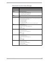
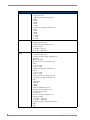
RS-232 Controller Command Messages ................................................................. 63
Delta Series Audio Controllers
iii
Table of Contents
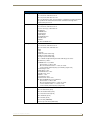
Delta Audio Controller Status Messages ............................................................... 67
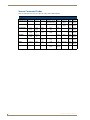
Source Command Codes......................................................................................... 70
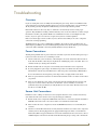
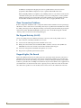
Troubleshooting ...............................................................................................71
Overview ................................................................................................................ 71
Power Connections ................................................................................................. 71
Source Unit Connections......................................................................................... 71
Zone Connection Problems..................................................................................... 72
No Keypad Activity (At All)..................................................................................... 72
Keypad Lights, No Sound ....................................................................................... 72
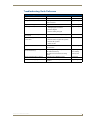
Troubleshooting Quick Reference ......................................................................... 73
iv
Delta Series Audio Controllers
Delta Series Audio Controllers
Delta Series Audio Controllers
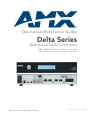
Overview
The Delta Series Audio Controller is an affordable, feature-rich multi-zone audio distribution system
that allows control and distribution of audio from 4 sources and to 4 or 6 zones.
The DAS-D0404 controls of up 4 sources and distributes audio to 4 rooms/zones.
The DAS-D0406 controls of up 4 sources and distributes audio to 6 rooms/zones.
Delta Series Audio Controllers are available in 120V (DAS-D0404 & DAS-D0406),
or 240V versions (DAS-DI0404 & DAS-DI0406).
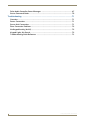
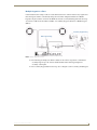
FIG. 1 indicates the front and rear panel components on the Delta Controllers.
Navigation Buttons
IR Receiver
Power Switch
& Receptacle
LCD Display Screen
AM/FM Antenna Inputs
Preamp Outputs
Source Inputs (up to 4)
IR Emitter
Outputs (4)
Zone Outputs
(up to 6)
RS-232 and USB
Expansion Port (RJ45)
FIG. 1 Delta Controller Layout - Front and Rear Panel Details (DAS-D0404 shown)
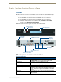
Product Specifications
Delta Series Product Specifications
Models Available:
• DAS-D(I)0404 4 Source, 4 Zone Controller (120V or 240V)
Stereo Output:
25 Watts/CH stereo (20Hz to 20Khz @ .1% THD)
Power:
287W max (Actual average usage = 120W)
• DAS-D(I)0406 4 Source, 4 Zone Controller (120V or 240V)
Front Panel Components:
• Navigation Array Buttons
Allow for front panel programming, selection of sources, and tuning
AM/FM radio stations (when Delta is fitted with the optional tuner
board). The same array appears on the Matrix KP-4e navigational
keypad.
• IR Receiver
For the IR receiver. This is where you must aim the remotes from
your audio source components so the Delta can learn and emulate
those commands.
Delta Series Audio Controllers
1
Delta Series Audio Controllers
Delta Series Product Specifications (Cont.)
• LCD Display Screen
Displays information necessary during the programming steps and
afterward is the display to indicate information about the source input
and zone activity.
Rear Panel Components:
• Power Switch & Receptacle
The master power switch will remain in the ON position normally.
• AM/FM Antenna Inputs
Connections for the AM and FM Antennas.
• IR Outputs (4)
Four 3.5mm IR Emitter Output Jacks.
Note: Be sure to connect the emitter to the same numbered port as
the corresponding source input.
• Zone Outputs (up to 6)
Connections for zone outputs that connect to the keypads.
• RJ 45 Port
Ethernet Port for future expansion
• RS-232 and USB Ports
For firmware upgrades and interface with NetLinx control systems.
• Source Inputs (up to 4)
RCA connections for 2-channel audio input from up to 4 external
sources (unless an AM/FM tuner board is present, which internally
takes up the Source #1 location - then it’s 3 additional sources).
• Preamp Outputs
RCA outputs to run an external amplifier. This is only available for
Zone output #1.
Dimensions (HWD) - including feet and
rear connectors:
• 3 1/16” x 17” x 13 1/2”
Weight:
24.05 lbs (10.91 kg)
• 7.68cm x 43.18cm x 33.52cm
Tuner Antenna Details
The TA-MOD tuner automatically becomes source #1 when installed into the Delta Controller
The TA-MOD tuner requires a 75 Ohm F-Type connection to receive FM stations.
The TA-MOD tuner requires an AM antenna loop to receive AM stations.
2
Delta Series Audio Controllers
Delta Installation - Quick Start Steps
Delta Installation - Quick Start Steps
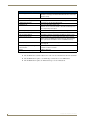
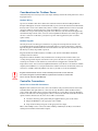
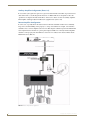
1. Connect the Source Units to Delta
Plug RCA audio cables from each source device into the labeled RCA jacks at the back of the Delta
Controller. Ensure that right and left are connected correctly. Then connect the IR emitter leads for each
audio source into the appropriate connector on the back of the Delta Controller and run the optical end of
the emitter lead to the source device’s IR receiver window.
Attach the emitter by peeling and sticking the supplied adhesive patch on the emitter. If an on-board
tuner is pre-installed into Delta, you must also connect AM and FM antennas as shown in FIG. 1.
IR Emitter Outputs (4)
Connections for IR emitter
outputs that control the sources
AM/FM Antenna Inputs
Plug in the IR Emitters to the
appropriate source number
Source Inputs (up to 4)
FIG. 1 Connect the Source Units to Delta
Source Inputs (up to 4)
RCA connections for 2-channel audio input from up to 4 external sources (unless an AM/FM tuner board
is present, which internally takes up the Source #1 location - then it’s 3 additional sources). The
illustration at left shows an example of a DVD player, CD player, and iPod docking device all connected
to Delta. The fourth source is the internal AM/FM tuner.
Delta Series Quick Start Guide
3
Delta Installation - Quick Start Steps
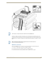
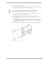
2. Connect the Keypads to Delta
Looking at the rear of the keypad with the connectors at the bottom, you will see (2) plug type 4 pin
receptacles. The connector on the right side terminates the 4 conductor wire from the Delta Controller
and the connector on the left side passes the audio to the speakers in the zone (FIG. 2).
Plug in the IR Emitters to the
appropriate source number
Be sure to match the color and position
of the wiring at the keypad with the
wiring at the Controller.
To Keypads
Wiring from the
Delta Controller
connects on the
right side of the keypad
FIG. 2 Connect the Keypads to Delta
Although speaker wire is commonly used, you can also use CAT-5 or other paired wiring.
Please see the complete Delta Installation Manual for details.
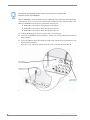
3. Connect the Speakers to the Keypads
Speakers will be wired according to their positive and negative terminals, which are usually Red and
Black for each speaker. Once installed in their locations, the speaker wiring is typically run to the keypad
location and is connected into the connector on the left side of the keypad. Repeat this for each zone in
the system (up to six). There are alternative connection schemes for speakers directly to Delta or via
external amplifier.
Wiring to the speakers connects
on the left side of the keypad
FIG. 3 Connect the Keypads to Delta
Please see the complete Delta Installation Manual for details.
4
Delta Series Quick Start Guide
Delta Installation - Quick Start Steps
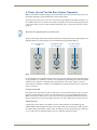
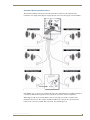
4. Power Up and Test the Basic System Operation
Make sure the Delta Controller is plugged into the wall and the power switch on the back panel is in the
ON position. The Delta system should now be ready for initial testing.
To test the system connections, activate one source from a keypad. Begin by manually activating one of
the available audio sources such as the tuner and move through each zone and test that keypads respond
to the on/off, volume, and tone control commands and that the source can be heard in all zones on both
speakers.
We assume the programming has not yet taken place
The basic functionality of the Delta Controller (which means turning Delta on/off, volume up/down and
treble/bass/balance) are functions that can be performed without programming (FIG. 4).
Press any Source Key
for "ON"
Use Keypad to adjust
Bass and Balance
Press Vol+ and Volto begin settings
FIG. 4 Power Up and Test the Basic System Operation
If a tuner module has been installed, all of the basic tuner operations will also be able to function without
any programming so you will have sound for a test signal right away. The IR repeaters must be installed
and basic source component commands must be programmed to select and/or control any external
sources however. Until then, you will have to manually turn on and start the external source component if
used as a test source!
Turning a Zone ON
Pressing the Source key turns the system on in the room you are in and also turns that source on if it has
not been previously selected in another zone. The indicator next to the source will light Red. Through
Matrix’s own Dynamic Macro process, sources that are muted or paused will be turned off after they are
idle (not selected in any zone) for ten minutes. Press the active source button again to turn the zone off.
Volume Control
Control of the system volume is very intuitive because of discrete buttons for the Volume UP and
Volume DOWN command. When increasing or decreasing volume, the progression is in 3dB steps when
the volume is half (of maximum) or below. Above the halfway point, the progression drops to 1dB steps
so you can fine tune the adjustment without worry of overdriving speakers by surprise.
Delta Series Quick Start Guide
5
Delta Installation - Quick Start Steps
Tone Control
The tone control mode allows the user to adjust Bass, Treble, and Balance on a “per zone” basis. To enter
tone control mode, press VOL UP & VOL DOWN buttons simultaneously until LED’s begin to cycle in
a counter-clockwise motion.
This will enable the BASS and BALANCE settings first. At any time during adjustments, If you want to
return the settings to default, press and hold the centre keypad navigation button. When you are satisfied
with your adjustment, press (but not hold) the centre keypad navigation button to save the bass and
balance adjustment. This will take you to the treble and balance adjustment mode. Once again, once
adjustments are complete, press (but not hold) the centre keypad navigation button to return to normal
operation mode.
5. Basic Programming
The key to successful programming is to understand how each of the source components operates.
Programming and IR Capture take place on the front panel of the Delta Controller. Settings such as Bass,
Treble, and Balance functions are programmed from within any zone using the keypad. We suggest you
read this section carefully in its entirety BEFORE starting to program the Delta Controller. This will
allow you to obtain a general understanding of what you will see and what to expect when you go
through the programming exercise.
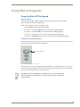
IR Learning Techniques
Programming techniques may need to be modified on a remote-by-remote basis. Some remotes may
need to be closer to or further away from the Delta Controller. Some may program better with quick key
presses and some with long key presses. Generally speaking, the audio source remote should be located
about 6-12 inches away from the IR receiver on the Delta Controller.
The path between the devices should be unobstructed with a clear line of sight.
Fluorescent light fixtures and bright sunlight may interfere with the learning process, so you may choose
to shade the IR receiver with a sheet of paper or other practical means. When possible use only
incandescent lighting during the programming session. During programming, distance between the
remote and the Delta Controller is also important. If the remote is too close to the unit the IR signal will
overload the learner. If it’s to far away, it might not learn due to weak signals strength. A bit of trial and
error will quickly get you to the correct distance.
Program Panel
The programming controls (also called the “navigational array”) and the IR receiver are located on the
front of the Delta Controller. The four directional buttons allow you to navigate through the menu
screens. The centre button is used to make selections (as if to press OK or ENTER).
Refer to the Programming the Delta System section on page 27 for detailed programming instructions.
6
Delta Series Quick Start Guide
Wiring and Connections
Wiring and Connections
Pre-Installation Precautions and Recommendations
The Matrix Delta system is extremely flexible. It can be installed in a number of configurations
depending on your audio needs. The capacity of a single unit is 6 independent zones and is typically
wired with at least one keypad located in each zone. In some cases it is desirable to operate a second set
of speakers within the same zone controlled by the same keypad. The Delta Controller will power 2 sets
of speakers as long as the impedance does not drop below 4 ohms. If you have two common zones such
as the Master Bedroom and Master Bathroom you can use the a single keypad and multiple analog
volume controls for independent control of the two areas while sharing the same source control
capability. Up to 2 Matrix keypads can also be connected in a zone as a with a single pair of speakers.
Each zone can be configured with either 2 pushbutton keypads (Numeric or Source),
or 1 LCD Keypad and 1 pushbutton Keypad, but not 2 LCD keypads.
See the Multiple Keypads in a Zone section on page 26 for details.
Note to Professional Installers
AMX always recommends professional installation for our products. As with any entertainment product
in a home or commercial application, a Delta system installation will go much faster and more smoothly
if job plans are completed prior to the actual installation.
Accurate record keeping will assist not only in the installation, but also in training the client in the
operation of the system. This will also be a great tool for any future servicing issues that may arise.
We recommend that you make copies of the records and leave them behind with your client as well as
putting a duplicate copy in your client’s file. For the professional installer’s convenience, programming
worksheets are available at www.amx.com.
Installing Source Equipment
To meet airflow and cooling requirements, place each audio source on an individual shelf and allow a
minimum of 3” clearance on the sides and top of the unit. Stacking equipment is not recommended as
this presents situations in which airflow is restricted or component cooling may be impaired. The audio
source equipment and the Controller will generate small amounts of heat that must be dissipated to
extend component life and maintain performance.
Equipment should have adequate room in the rear for the cables to reside. If rear access, or a rack a
mounted structure has been provided then cable installation will be much easier.
Cabling Installation Instructions
Please be sure to check for any wiring restrictions required by the electrical code in your area.
This installation uses low voltage cabling similar to telephone and alarm wiring, and as such does not
commonly have very many restrictions on their installation. However rules may vary in different regions.
Please check with your local code enforcement official to determine if any specific conditions must be
met to comply with local electrical codes.
Delta Series Audio Controllers
7
Wiring and Connections
Cable Type
The Delta Controller is cabled using standard 4-conductor speaker cable originating at the Delta control
unit passing through the keypad and terminating at the speaker location. Matrix Audio Designs generally
recommends using a bundled 4 conductor 16 gauge stranded copper wire in a single continuous run. The
keypads also function with Cat 5 or basically any 2 conductor wire configuration that is not used for
other devices.
RF Interference
Shielded cable is generally not required for audio installations. Although the Delta Controller does
generate very low radio frequency emissions, it uses a digital signaling path during command entry.
There are normally no ongoing data communications in the circuit path. Communications only occur at
the time a command is issued from a zone. However many other systems do use microprocessor systems
where the cabling may be in close proximity such as telephone and security systems, and it is possible
for different systems to interfere with each other. If you face an installation where your cable runs are in
parallel to these types of systems you may consider shielded cable to the keypads. In this case ground the
drain wire by connecting it to the chassis of the Delta Controller.
Distribution Wiring
In general, wiring is installed in a single continuous run between the Delta Controller, the keypad and the
speaker location. Other cable routing options such as a home run to a common wiring distribution point,
integration with home automation systems, or split zone applications can be significantly different than
the general information presented here. These applications are left to the installer’s discretion and
experience, which is why Matrix Audio recommends installation by a professional. Examples of
common wiring options can be found in the “Controller Connections” section of this manual.
Considerations for New Construction Installations
It’s generally accepted to run the 2 and 4 conductor speaker cables inside walls, in the attic and between
the joists in the basement or crawl space. When installing cables within walls, drill the holes in the
middle of the studs to avoid having them damaged by screws or nails that could penetrate the cable. Use
metal nail guard plates where necessary to protect the cable from future construction damage or from
something like nails/screws that are installed to hang future pictures or shelving. When running cables in
the attic or crawl space, run them in such a way that they will be out of harm, where they will not be
stepped on, snagged, punctured, or could pose a safety hazard.
Do not run cable thru the return air path that utilizes the wall or ceiling space as the plenum.
Securing the Cables
We recommend using electrical cable straps to keep the installation neat and secure. We do not
recommend stapling the cables as a single misplaced staple can cause a short that causes trouble during
operations and set-up. Do not leave the wires lying in the dirt under the crawl space.
Neatness counts in a professional installation.
Keypad “Rough In” Locations
The keypad device itself will fit in a standard electrical box or new construction plate and you should
install 1 or 2 gang (as required) standard electrical boxes to accommodate them before the drywall has
been put into place. Keep in mind that because these are low voltage applications, plastic electrical boxes
are generally adequate for the keypad, but check local building code requirements to be sure. The high
voltage electricians on the job site will know which electrical box is appropriate and within code.These
emissions have been accommodated for in design and conform to RF emission standards.
8
Delta Series Audio Controllers
Wiring and Connections
Considerations for Existing Construction
For existing construction, successful implementation can be achieved by using retrofit electrical boxes
that do not require stud mounting or metal electrical frames which are commonly used for telephone and
cable installations. These “afterthought” low voltage electrical boxes can be placed in a standard opening
in the wall. Care must be taken when using these frames that they must not come in contact with the back
of the unit, or provide a shorting path at the cable connections.
When installing near other switches, make sure the boxes are dead level and lined up with existing
electrical boxes.
Running Wires in Existing Construction
A neat and careful installation in an existing construction application will increase the customer
satisfaction level as well as reduce the chance of service calls in the future. Run cables inside the walls
(wherever possible) to the attic, basement, or crawl space. Some installers cut the long straight section
from a coat hanger and chuck it into a drill to help establish a reference marker through ceilings and
floors up against the edge of a wall. The coat hanger wire is tough enough to drill through most materials
without snagging the carpet fibers. The wire is fairly unobtrusive and the length makes it easy to spot on
the other side. The small hole left behind is usually hidden by the carpet, or easily repaired. Holes in the
stud wall for the wiring can then be made by taking into account the width of the baseboard, drywall, and
half the stud (usually 1/2” + 1/2” + 1- 1/ 2 or 2- 1/ 2” from the pilot hole.)
If you must run wires in a room that is carpeted, you can carefully place the cables under the baseboard
or you can lift the edge of the carpet and place the wiring between the carpet’s tack strip and the wall. Be
careful going past doorways or across a walking path. A cable doesn’t seem too big until it’s tripped over
or causes an unsightly lump in the carpet, so please consider cable diameter where necessary. In some
cases when running wire under carpet or a threshold, you may discover that multiple 2 conductor speaker
wiring will sit flatter than a single bundled 4 conductor wire.
Marking the Cables
When running each cable, carry a fine tip permanent marker with you and mark both ends of the cable.
When you get to the keypad location, mark a couple of arrows on the cable to show you in which
direction the speakers are and in which direction the Delta Controller is. This will save you time,
eliminating the need to “Ohm-out” the cables later to find the one you’re looking for. A few additional
seconds spent during the wiring stage will save you hours of cable chasing later.
Existing Electrical Boxes for Keypads
Due to the varying manufactured sizes of electrical plates and boxes carefully mark a level and plumb
outline of the switch box using the box itself as a template and make a hole in the existing wall with a
drywall or reciprocating saw. Please be careful to ensure that the space you’re cutting into does not hide
any plumbing, electrical or heating fixtures that could be damaged or cause personal injury. Care must
also be taken when dealing with outside walls. The vapor barrier should be repaired if damaged.
Delta Series Audio Controllers
9
Wiring and Connections
Considerations for Outdoor Zones
Outdoor listening zone locations present some unique challenges, both for the wiring and for the control
keypad placement.
Outdoor Wiring
Special care should be taken when cables transit outside the structure. External cabling should run
through conduit (plastic electrical conduit works well) to protect it from the elements and small animals
that may wish to chew on the cable.You may wish to consider a qualified electrical contractor to install
electrical conduit for external applications. Cable and installation accessories to complete your
installation are not part of the system package but can be obtained at your local electrical supply house,
national home improvement centres, and even at most neighborhood hardware stores. These places may
also have a selection of cable that’s geared just for specific outdoor applications (such as “buried”
speaker cables).
Outdoor Keypads
Choosing the location of the keypad control device is perhaps the most important decision. It is not
recommended that keypads be installed in environments subject to extreme temperatures, or moisture.
Typically keypads are installed inside the home and beside the door adjacent to the outside music zone,
but this may not always be possible or practical.
Keypads that must be installed outside are installed at your own risk and should be installed in
weatherproof electrical boxes.
Keypads used outdoors should be safely mounted inside a weatherproof electrical box with a door
covering the keypad and adequate water barrier seals to protect the unit. Once again, the appropriate
weather proof enclosures can be obtained at your local electrical supply house, national home
improvement centres, and even at most neighborhood hardware stores. Be sure to check what is available
and plan your installation before doing the work with an outdoor zone because the materials you have (or
do not) have available could easily influence the choices you make to execute the installation.
Keypads installed outside must be inside a weatherproof box with a cover that seals
out moisture. Keypads returned to AMX for repair that are found to be corroded will
not be covered under the AMX Warranty.
Controller Connections
Source Unit to Controller Connections
Plug RCA audio cables from each source device into the RCA jacks provided on the back of the Delta
Controller. Ensure that right and left are connected correctly. The balance will be backward on that
source and the audio will not image properly if right and left are reversed. Then connect the IR emitter
leads for each audio source into the appropriate connector on the back of the Delta Controller and run the
optical end of the emitter lead to the source device’s IR receiver window.
Attach the emitter by peeling and sticking the supplied adhesive patch on the emitter.
Plug in the IR Emitters to the appropriate source number.
Strip and attach wiring to keypads on the appropriate zone output.
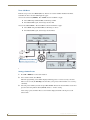
FIG. 5 shows multiple sources connected to Delta including a DVD Player, CD Player, and an iPod
docking station with IR control and RCA outputs.
10
Delta Series Audio Controllers
Wiring and Connections
FIG. 5 Source Unit to Controller Connections
Source Input #1 is left open because the default is the internal AM/FM tuner.
The Delta Controller learns the IR commands for power on/off during the programming setup. Source
components are turned on when they are selected on the keypad. The source remains on until it has been
idle in all zones for a duration of 10 minutes, then Delta will automatically turn it off until it is selected
again.
Make sure that the IR emitter output is plugged into the same numbered IR port as
the source component input RCA jacks.
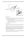
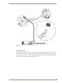
AM/FM Tuner Connections
The internal AM/FM tuner does not require any special programming or setup other than presets.
1. Connect a 75 Ohm adaptor and antenna to the FM coaxial plug.
2. Connect the two leads of an AM loop antenna to the AM spring clips.
3. Position both antennas as high as possible to allow for optimal station reception.
Delta Series Audio Controllers
11
Wiring and Connections
Depending on the installation location, it may be necessary to use a powered FM
antenna to receive clear FM stations.
When an AM/FM tuner has been installed, input #1 will default to the internal tuner and the RCA input
jacks will not be active for source #1. If no internal tuner is installed, the source #1 inputs will be active.
Either way, Source#1 is activated by the top-left button on the keypads.
Source #2 is activated by the top-right button on the keypads.
Source #3 is activated by the button directly below source #1
Source #4 is activated by the button directly below source #2.
See “Using the Matrix Keypads” for more details on how to use the keypads.
4. Connect the 75 Ohm FM antenna by pushing the “F Connector” on to the terminal at the back of the
Delta Controller.
5. Connect the AM loop antenna by inserting the stripped wire ends into the spring loaded jacks at the
back of the Delta Controller.
Since this a “loop” antenna, the position of the wires in the jacks does not matter (FIG. 6).
FM antenna
connects here
AM antenna
connects here
FIG. 6 AM/FM Tuner Connections
12
Delta Series Audio Controllers
Wiring and Connections
Standard 4 Wire Keypad Connections
The standard installation of keypads to the Delta Controller is with 4 wires directly between the
Controller’s zone output and the keypad’s input (right side connector of the keypad), as shown in FIG. 7.
FIG. 7 Standard 4 Wire Keypad Connections
If the building was “pre-wired” for standard audio, this is the configuration they most likely intended. If
you wired (or will wire) the keypad locations yourself, this is the most common configuration.
When stripping cable for use with the Molex connector, only strip away about 1/4” (6mm) of the
insulation from each wire. The complete assembly should not have any bare wire exposed from the
bottom of the connector if possible. This is the safest, most reliable approach.
Delta Series Audio Controllers
13
Wiring and Connections
2 Wire Keypad Connections (Control Only)
In some retrofit configurations it is not feasible or possible to re-route the speaker cable through the
keypad. In cases such as this, it is possible to run a separate cable pair (CAT- 3 / CAT- 5 / CAT- 6 /
Twisted Pair / Other 2 conductor wiring) cable from the Delta Controller to the keypad device for control
purposes. This diagram shows the connections of the control signal path to the keypad and the speaker
connections directly to the Delta Controller (FIG. 8).
FIG. 8 2 Wire Keypad Connections
Keypad wiring uses just two conductors. These could easily be Cat 3/5/6 or generic 2 conductor wiring.
Use only the D (DATA) and G (GROUND) terminals for the output of this connection. Speakers connect
directly to the Delta Controller as shown in FIG. 8.
Speaker wiring connects directly to the Delta zone output. Left and Right speaker positives connect to
the L and R terminals respectively. Both speaker negatives connect to the G terminal (which will share a
connection with the G wiring to the keypad).
14
Delta Series Audio Controllers
Wiring and Connections
Multiple Keypads in a Zone
Certain situations such as large rooms or rooms with more than one common entrance may require more
than one keypad control to conveniently manage the zone. This configuration allows for 2 Matrix
keypads to be placed on the control circuit. Make sure that the second (AUX) keypad has the wire loop
cut so that it’s addressed to the Delta Controller as an auxiliary keypad, rather than a “MAIN” keypad
(FIG. 9).
Secondary Keypad wiring
Main Keypad wiring
FIG. 9 Multiple Keypads in a Zone
The main keypad wiring uses all four conductors and connects to speakers as normal. The
secondary keypad “taps off” of the D and G terminals of the main keypad input for a
secondary control point.
The secondary keypad must have the loop cut to configure it as the secondary (AUX) keypad.
Delta Series Audio Controllers
15
Wiring and Connections
Matrix Keypad plus Analog Volume Controls
In cases of split zones where more than one set of speakers are driven from the same zone output (such as
a master bath off of the master bedroom) it is sometimes desirable to place independent volume controls
in the split zones while retaining the Delta Keypad for source control and ON/OFF functions.
FIG. 10 shows the connections to a remote zone and “Autoformer” volume control devices.
Secondary analog
volume control
Main Keypad wiring
FIG. 10 Matrix Keypad plus Analog Volume Controls
Total impedance on the zone MUST NOT be below 4 Ohms!
The secondary analog volume control “taps off” of the L+, G and R+ terminals of the DELTA
CONTROLLER OUTPUT. The G terminal connects to both L- and R as shown. This allows
independent volume in each “sub zone” with the Delta Keypad being the source control and
ON/OFF switch.
The main keypad wiring uses all four conductors and then a secondary analog volume control
“taps off” of the L+, L-, R- and R+ terminals of the SPEAKER OUTPUT for the main zone.
16
Delta Series Audio Controllers
Wiring and Connections
Auxiliary Amplifier Configuration (Zone 1)
In some cases you may require more power for a given zone than the Delta Controller can provide.
FIG. 11 shows how to utilize the preamp RCA outputs on the Delta Controller for an external amplifier.
This may be useful when outdoor or large rooms make up the zone, or in situations where the number of
speakers will require a multi-channel amplifier to safely power them all.
FIG. 11 Auxiliary Amplifier Configuration
This configuration shows an external power amplifier connected to the “LINE OUT” connections on the
back of the Delta Controller. These connections are only available on Zone 1. The corresponding Zone 1
keypad would connect to the Delta Controller with only the D and G connections. The power amplifier
will handle the individual speaker connections which means the amplifier and the speakers can be placed
at distances from the Delta Controller not usually practical. It also allows an easy solution when you
simply need more power in the zone than the Delta Controller provides
Delta Series Audio Controllers
17
Wiring and Connections
Auxiliary Amplifier Configuration (Zones 2-6)
In cases where you require more power for a given zone than the Delta Controller can provide and it is
other than in Zone 1, use this diagram. It shows use of a Matrix LLC device designed to reduce the
“speaker level” output of the Delta Controller to “line level” so that it can drive an auxiliary amplifier.
This amplifier would typically be installed at the equipment rack (source end).
Remote Amplifier Configuration
In some cases, especially where the distance between the Delta Controller and the zone is unusually
long, such as another building on the property i.e. cottage-to-boathouse for example, it is sometimes
desirable to have a remote amplifier at the zone end. This diagram could also represent the Matrix LLC
device implemented so that there is a preamp level output available for a remotely mounted amplifier
elsewhere on the property. The main difference is the run of 4 conductor wire between Delta and the
Matrix LLC device (FIG. 12).
FIG. 12 Remote Amplifier Configuration
18
Delta Series Audio Controllers
Wiring and Connections
Connecting the RS-232 Serial Port
Delta Audio Controllers provide an RS-232 (DB9) port for receiving RS-232 Controller Commands.
Refer to the RS-232 Controller Command Messages section on page 55 for a complete listing of
supported commands.
Connector: DB9 Male
Communications: 4800 Baud, 8 data bits, 1 stop bit, no parity
The Matrix Distributed Audio, multi-room audio control systems can be externally controlled by sending
ASCII text command strings to the Bi-Directional RS-232 serial interface. Every command must be
terminated with a line feed (0x0A). All messages are case-sensitive.
The MRC will respond to command messages with a status response message once the command has
been executed.
RS-232 Cable
When connecting to the RS-232 port located on the back of the Delta Controller, it is necessary to use a
DB9 cable. Delta Controllers utilize DCE protocol therefore no NULL modem adapter is necessary. You
may also use a USB to DB9 adapter.
Connecting Matrix Keypads
Tools Required for Installation
Tools you’ll need to complete this part of the installation are wire strippers, small standard slotted
screwdriver and a permanent marker. An optional tool is an ohmmeter to determine which side of the
wire you are working with if they were not marked. If the wires are not secured to an electrical box use
masking tape to help secure the cable while you are working on it. There is nothing more frustrating than
having the cable fall back behind the wall. It’s also recommended to have a Speaker Impedance Meter
(not just a DMM) so that you can accurately read speaker impedance.
Orientation of Connectors
Looking at the rear of the keypad with the connectors at the bottom, you will see (2) plug type 4 pin
receptacles. Generally the mating connector parts shipped in a separate hardware bag that is packaged
with the Delta Controller.
The connector on the right side terminates the 4 conductor wire from the Delta Controller and the
connector on the left side passes the audio to the speakers in the zone. The Matrix keypad is distinctively
marked on the back, and the connector on the right side is labeled vertically indicating the line from the
Delta Controller and the connector on the left side is labeled vertically indicating the line leading to the
speakers, so this should make installation less of a guessing game.
Be sure to match the color and position of the wiring at the keypad with the wiring at the Controller
(FIG. 13).
Delta Series Audio Controllers
19
Wiring and Connections
Wiring TO the
speakers in the
zone connects here
Wiring FROM
the Delta Controller
connects here
Match the color/position of the wiring
at the Keypad with the wiring at the Controller
FIG. 13 Orientation of Connectors
Preparing the Wires
When working with the SWT connector, only strip away about 1/4” inch (about 6mm) of the insulation
from each wire. Most common electrical problems occur when the wire is stripped too long, and they
short out against neighboring wires behind the wall.
The complete assembly should not have any bare wire visibly exposed from the bottom of the
connector. A quick twist of the copper strands will ensure easy installation into the connector.
Tighten the fastening screw securely.
Ensure that wire strands do not touch neighboring wires on the connectors, as this could result
in malfunction or impede system performance.
Wire Color Schemes
It’s not particularly important to denote any one color as any one particular conductor. What is, however,
of critical importance is consistency in your wiring scheme with respect to which color goes into which
position.
For example, if you always start left to right and use Red on Pin #1, Black on Pin #2, Green on Pin #3
and White on Pin #4, then it will always be wired correctly between the Delta Controller and the keypad
input. This configuration also places Green as the ground wire - which is consistent with most home
wiring standards. Although the actual colors in the example are not absolute, it’s important that those
colors follow the same left to right position in each connector location at both the right side of the keypad
and the Delta Controller. The most common installation errors are caused from not following a
consistent wire color and pin location format.
Speakers are wired according to their positive and negative terminals, which are usually Red and Black
for each speaker, and those will be connected into the connector on the left side of the keypad. See the
Connecting Matrix In-Ceiling Speakers section on page 22 for details.
20
Delta Series Audio Controllers
Wiring and Connections
Installation into the Wall Cavity
1. After wiring is complete, simply push the wiring back into the wall cavity and make sure there is
enough room for the Matrix keypad to comfortably fit into the opening.
Do not force the keypad up against wiring or other obstructions if it cannot fit flush to
the mounting holes because damage can occur to the circuit board of the keypad.
2. Once the keypad had been set into the wall opening, line up the mounting holes with the receiving
threaded holes in the wall plate (or electrical box).
3. Begin threading the top and bottom screws by hand and finish with a screwdriver.
4. Once the installation is complete, snap on the cosmetic trim panel and install any additional
remaining keypads.
5. Once the keypad wiring is connected and correctly plugged in, install the keypad into the wall cavity
with the supplied screws. Make sure there is no binding of the wiring and that the keypad fits
without forcing it into the opening.
6. After the keypad is secure, proceed with the installation of the decorative trim panel (FIG. 14).
FIG. 14 Installation into the Wall Cavity
Delta Series Audio Controllers
21
Wiring and Connections
Connecting Matrix In-Ceiling Speakers
Overview - Speaker Wire Technology (SWT)
Speaker Wire Technology (SWT) allows both data and audio signals to travel over the same four
conductor wire. This is the same four conductors that you would run (or is run) in your home wiring
installation for a standard speaker and volume control installation. This remarkable technology removes
the need for control wire since the control and audio signals are shared on the same wire. The reliability
and simplicity of this system has been proven for years in both existing homes as well as brand new
multi-room installations.
SWT simply replaces standard “rotary” or “slide” volume controls with Matrix Audio keypads and a
Controller like Delta, giving full control over the sources. Additionally, the versatility of SWT also
allows Matrix Audio products to be connected where the control wire has been run separately from the
speaker cable, so installations are easier than ever before.
Overview - Matrix Speakers
Matrix in-ceiling speakers provide exceptional acoustical performance using superior components and
crossover design. Matrix speaker enclosures incorporate a floating bridge, which houses a unique
pivoting tweeter assembly that creates directionality for the user.
The Delta system can be used with the Matrix Audio Active Speaker system. This speaker system is an
active design that connects directly to the Matrix Controller and has an IR receiver so there is no need for
a keypad in the zone. The remote control can handle all of the zone functions simply by pointing at the
speaker.
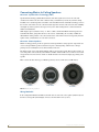
FIG. 15 shows the three main types of Matrix speakers (C Series, C-DT Series and EL Series):
C Series
C-DT Series
EL Series
FIG. 15 Matrix In-Ceiling Speakers
Wiring Method A
In the configuration illustrated in FIG. 16, all four wires are run to the active speaker (shown Left) and
then the second speaker (shown Right) connects to the first with 2 wires (+ and -).
22
Delta Series Audio Controllers
Wiring and Connections
FIG. 16 Wiring Matrix Active Speakers - Method A
Method B (Retrofit)
In the configuration illustrated in FIG. 17 (typical in retrofit applications where wiring is in place), each
speaker has a 2 wire feed and a “4 wire bridge” connection must be installed between the two so that the
active (4 terminal) speaker can receive a full 4 wire input (using 2 of the 4 wires) and then bring audio
back to the second speaker through the remaining 2 wires.
Delta Series Audio Controllers
23
Wiring and Connections
FIG. 17 Wiring Matrix Active Speakers - Method B
24
Delta Series Audio Controllers
Wiring and Connections
Delta Series Audio Controllers
25
Wiring and Connections
26
Delta Series Audio Controllers
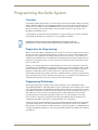
Programming the Delta System
Programming the Delta System
Overview
Programming and IR Capture take place on the front panel of the Delta Controller. Settings such as Bass,
Treble, and Balance functions are programmed from within any zone using the keypad. We suggest you
read this section carefully in its entirety BEFORE starting to program the Delta Controller. This will
allow you to obtain a general understanding of what you will see and what to expect when you go
through the programming exercise.
Careful planning, documentation and experimentation on your part with the sources prior to taking the
programming on will allow you to experience an easy and painless installation.
Programming is EASY and only seems complicated if you are trying to solve all
operating issues at the same time! Please take the time to read this section carefully.
Preparation for Programming
Make certain you have all the documentation and accessories for each source component (the operator’s
manuals, the remote controls with working batteries. You may need to reference their manuals to learn
the operation of the equipment and you will certainly need to use the remotes to “teach” Delta what
commands it must emulate. Since new equipment is rarely shipped with the batteries installed, make sure
the batteries are installed or, in the case of an existing source component, make sure the batteries in the
remote are functional.
The key to successful programming is to understand how each of the source components operates. By
determining how you would like the components to function as part of the home audio system you will
be able to spend less time on the programming phase of the installation. You should take some time to
familiarize yourself with the basic operation of the source component’s remote control to better
understand the operating characteristics of the device and which functions you wish to program into the
Delta Controller. If you can operate and manage the audio device as a stand alone unit, it will aid you in
determining which functions you want to program into the Delta Controller.
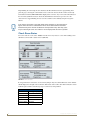
Programming Worksheets
Before getting started, please outline how the system is intended to operate using Matrix Audio’s
“Programming Worksheets”. This outline will assist you in setting up the remote training session as well
as the other Delta functions. You will find this worksheet will not only help you plan in advance how the
keypad buttons will perform each function, but they will also assist in the event that IR codes, Presets, or
other settings need to be re-learned or changed down the road. This will reduce the time needed to
program/reprogram the Controller and keypads. It will also be your guide should any of the audio
devices need to be changed out or upgraded in the future. You will know what the original device’s
configuration looked like so the keypads can be labeled in the same configuration.
Consistency in the keypad programming and clear documentation will reduce frustration and shorten the
operational learning curve for your client. Remember that even though an experienced user will find
Delta operation easy, the first time user will do best when a “pattern of operation” is established through
consistent, thoughtful programming. A copy of the programming worksheet is available on the following
page (FIG. 18).
Delta Series Audio Controllers
27
Programming the Delta System
FIG. 18 Programming Worksheet
28
Delta Series Audio Controllers
Programming the Delta System
Accommodating Multiple Device Programming
Programming is an interactive exercise between you, the Delta Controller and the audio source remote
control, which may vary from unit to unit. You will learn the techniques to best train the Delta Controller
through some trial and error and observation. The audio source remote should be located about 6-12
inches away from the IR receiver on the Delta Controller. The path between the devices should be
unobstructed with a clear line of sight. Fluorescent light fixtures and bright sunlight may interfere with
the learning process, so you may choose to shade the IR receiver with a sheet of paper or other practical
means. When possible use only incandescent lighting during the programming session. During
programming, distance between the remote and the Delta Controller is also important. If the remote is
too close to the unit the IR signal will overload the learner. If it’s to far away, it might not learn due to
weak signals strength. A bit of trial and error will quickly get you to the correct distance.
Your programming technique may need to be modified on a remote-by-remote basis. Some remotes may
need to be closer to or further away from the Delta Controller. Some may program better with quick key
presses and some with long key presses. Some may require a change in distance and angle between the
remote and the Delta Controller. If a particular method doesn’t seem to be working for you, try to modify
your approach to understand the characteristic behavior of the source component remote so that it can
“speak” to the Delta Controller correctly.
Program Panel
The programming controls (also called the “navigational array”) and the IR receiver are located on the
front of the Delta Controller. The four directional buttons allow you to navigate through the menu
screens. The center button is used to make selections (as if to press OK or ENTER).
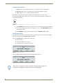
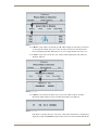
Enter the Program Mode
Press the center button on the front panel to enter the Main Menu. This will display four options, Setup,
Preferences, About and Exit (FIG. 19).
FIG. 19 Enter the Program Mode
The menu selection immediately defaults to the Exit selection in the first screen. Navigational buttons
(Left/Right/Up/Down) allow user to navigate through menu item.
Nav UP & Nav << both move the cursor UP or “back”. Nav.
DOWN & Nav >> both move the cursor DOWN or “forward”
The center button allows user to select menu items.
“Exit” takes user back to previous screen. In the first program menu screen, this would then
take you back to “default” screen (with the “M”).
Delta Series Audio Controllers
29
Programming the Delta System
Program Menu Selections
Setup is where the user will program Sources, access Tuner and Clock information.
Preferences allow user to set up preferences for Backlight and Display Options.
About displays the Version # for the Controller firmware.
Each of these program menu selections is detailed in the subsequent pages of this section.
In screens with multiple lines of selections, an arrow is used to indicate which line of information is
currently active (FIG. 20).
FIG. 20 Arrow Indicates Which Line of Information Is Currently Active
Nav UP/DOWN moves the arrow focus between the active and inactive lines of information.
Once the programming selections the user wants are “active”, Nav LEFT/RIGHT will move
from option to option.
Nav CENTER is used to make a selection as if to be an ENTER or OK command.
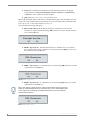
Setup Program Menu
The menu selection immediately defaults to the Exit selection in the first screen of the Program Menu.
The other menu choices are Controller, Tuner and Clock.
Selecting Controller(FIG. 21) will lead the user through:
Program Sources.
View the Room Info for each zone.
Adjust the Source Leveling for each source.
FIG. 21 Setup Menu - Controller
Selecting “Tuner” (FIG. 22) will lead the user through setting the presets.
FIG. 22 Setup Menu - Tuner
“Tuner” will only be displayed if a Tuner is detected on board the Delta Controller. If a
tuner board is not installed, there will be no “Tuner” selection displayed.
30
Delta Series Audio Controllers
Programming the Delta System
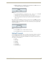
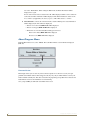
Selecting Clock (FIG. 23) will allow the user to set the Clock Time/Date/Day for the System.
FIG. 23 Setup Menu - Clock
Selecting Exit exits to the Main Menu (FIG. 24).
FIG. 24 Setup Menu - Exit
Controller Sub Menu
Programming Source Components
1. From the Setup screen, select Controller. The Controller Setup screen will be displayed.
The menu selection immediately defaults to the Exit selection in the first screen of the Controller
Set Up Menu.
2. Using the navigation button, select Program and the Program Sources screen will be displayed.
3. Select a Source to program.
If an on-board tuner is present, Source #1 will not be displayed since the Tuner takes
up the Source #1 location
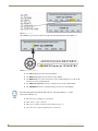
4. Once a source has been selected, the Select Source Type screen will be displayed. The menu
selection immediately defaults to the Learn IR selection in the first screen of the Select Source Type
screen (FIG. 25). The source number is displayed at the top of the screen.
FIG. 25 Select Source Type - Learn IR
Learn IR will allow user to learn IR commands for the selected source
Delay allows user to add a delay to all IR commands learned for the selected source type
Label allows customization of the label for each Source Type
Quit returns user to Please Select a Source screen.
If the Source Type has not been previously selected, Select Source Type will be
displayed, otherwise it will display the named source(s) from prior programming
sessions.
Delta Series Audio Controllers
31
Programming the Delta System
5. Press Next /Prev to scroll through the following available source names and profiles:
Select Source Type (default)
Tuner
CD
DVD
Satellite
Aud Server
Other
Delphi XM
See the keypad functions of each “Profile” in the Keypad Functions By Profile table
on page 33. This will help you understand what it will be like to operate the source
component through Delta.
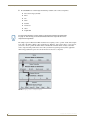
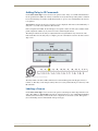
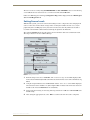
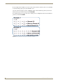
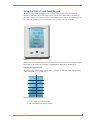
The sample sequence illustrated in FIG. 26 shows how assigning a source “profile” works. The example
is for Source #2 (which could be a CD or DVD player). When the “Select Source Type” screen appears,
you need to choose a profile that allows Delta to emulate IR commands which correctly control the
source component. The profile of the device tells you which navigator keypad and (where applicable
numeric keypad) buttons operate the various functions of the source component.
FIG. 26 Assigning a Source - Sample Sequence
32
Delta Series Audio Controllers
Programming the Delta System
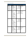
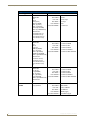
Keypad Functions By Profile
Keypad Functions By Profile
Source Type
IR Commands Learn...
Tuner
POWER ON
POWER OFF
SEEK + (kp UP)
SEEK - (kp DOWN)
BAND (kp DOWN)
MO/ST (kp CENTER hold)
Please note that
this selection is
intended for an
external AM/FM tuner.
If you have an
internal Matrix tuner
module, Delta will
have already assigned
it to Source #1
CD
Direct Access:
Nav. Button Functions and Result
Nav. UP = Next Channel
Nav. DOWN = Previous Channel
Nav. LEFT = Guide Down
Nav. RIGHT = Guide Up
Nav. CENTER = Select
Press/hold CENTER = Guide
DIRECT entry start seq.
DIRECT entry end seq.
0-9
POWER ON
POWER OFF
PLAY
PAUSE
TRACK + (kp UP)
TRACK - (kp DOWN)
DISC - (kp LEFT)
DISC + (kp RIGHT)
UDEF1 (kp CENTER)
UDEF2 (kp CENTER hold)
Nav. UP = Next Track
Nav. DOWN = Previous Track
Nav. LEFT = Previous DISC
Nav. RIGHT = Next DISC
Nav. CENTER = User Defined 1
Press/hold CENTER = User Defined 2
Direct Access:
Direct DISC start seq.
Direct DISC end seq.
Direct TRACK start seq.
Direct TRACK end seq.
0-9, (10+)
DVD
POWER ON
POWER OFF
PLAY
PAUSE
UP (kp UP)
DOWN (kp DOWN)
LEFT - (kp LEFT)
RIGHT + (kp RIGHT)
SELECT (kp CENTER)
MENU (kp CENTER hold)
Nav. UP = UP
Nav. DOWN = DOWN
Nav. LEFT = LEFT
Nav. RIGHT = RIGHT
Nav. CENTER = SELECT
Press/hold CENTER = MENU
Direct Access:
Direct DISC start seq.
Direct DISC end seq.
Direct TRACK start seq.
Direct TRACK end seq.
0-9
SATELLITE
POWER ON
POWER OFF
CH+ (kp UP)
CH- (kp DOWN)
GUIDE - (kp LEFT)
GUIDE + (kp RIGHT)
SELECT (kp CENTER)
GUIDE (kp CENTER hold)
Nav. UP = Next Channel
Nav. DOWN = Previous Channel
Nav. LEFT = Guide Down
Nav. RIGHT = Guide Up
Nav. CENTER = Select
Press/hold CENTER = Guide
Direct Access:
DIRECT entry start seq.
DIRECT entry end seq.
0-9
Delta Series Audio Controllers
33
Programming the Delta System
Keypad Functions By Profile (Cont.)
Source Type
IR Commands Learn...
AUDIO SERVER
POWER ON
POWER OFF
PLAY
PAUSE
NEXT (kp UP)
PREV (kp DOWN)
PAGE - (kp LEFT)
PAGE + (kp RIGHT)
SELECT (kp CENTER)
UDEF1 (kp CENTER hold)
Nav. Button Functions and Result
Nav. UP = Next
Nav. DOWN = Previous
Nav. LEFT = Previous Page
Nav. RIGHT = Next Page
Nav. CENTER = Select
Press/hold CENTER = User Defined 1
Direct Access:
Direct PAGE start seq.
Direct PAGE end seq.
Direct TRACK start seq.
Direct TRACK end seq.
0-9
OTHER
POWER ON
Nav. UP =
POWER OFF
Nav. DOWN =
PLAY
Nav. LEFT =
PAUSE
Nav. RIGHT =
UP (kp UP)
DOWN (kp DOWN)
Nav. CENTER =
LEFT - (kp LEFT)
Press/hold CENTER =
RIGHT + (kp RIGHT)
CENTER (kp CENTER)
HOLD C (kp CENTER hold)
User Defined UP
User Defined DOWN
User Defined LEFT
User Defined RIGHT
User Defined CENTER
User Defined HOLD CENTER
Direct Access:
Direct DISC start seq.
Direct DISC end seq.
Direct TRACK start seq.
Direct TRACK end seq.
0-9
DELPHI XM
POWER ON
Nav. UP =
POWER OFF
Nav. DOWN =
CH+ (kp UP)
Nav. LEFT =
CH- (kp DOWN)
Nav. RIGHT =
CAT - (kp LEFT)
CAT + (kp RIGHT)
Nav. CENTER =
XM (kp CENTER)
Press/hold CENTER =
HOLD C (kp CENTER hold)
User Defined UP
User Defined DOWN
User Defined LEFT
User Defined RIGHT
User Defined CENTER
User Defined HOLD CENTER
Direct Access:
0-9
MATRIX ON-BOARD
TUNER
The Tuner is already
pre-programmed
Nav. UP = SEEK UP
Nav. DOWN = SEEK DOWN
Nav. LEFT = Previous PRESET
Nav. RIGHT = Next PRESET
Nav. CENTER = AM/FM (toggle)
Press/hold CENTER = Stereo/Mono (toggle)
34
Delta Series Audio Controllers
Programming the Delta System
Learning IR Commands
Before programming any remote commands into Delta, make sure you understand
the button labels that Delta assigns a source component’s IR commands based on
the “source type” as shown on the previous pages.
When the “Learn IR” screen asks for a command, use the exact command from the
remote. Use the exact sequence that you normally would to turn on the source
component. As Delta learns this command, it will be exactly what it then emulates to
the IR emitter that will command the source component through Delta.
Take your time!!!
After selecting the profile of the source type, it’s time to teach the Delta Controller the IR commands
from the source component’s remote control. The Learn IR selection is your next programming choice.
Depending on your profile selection, most of the buttons on the Delta Controller and Matrix keypads will
already be intuitively assigned. There will be instances where something is labeled User Defined and it
will indicate the button/action sequence that is assigned to that user defined command. The actual
command from the source component’s remote could be anything you want, but the way Delta activates
that command will be described in that user defined command sequence (usually press or press hold a
specific button).
FIG. 27 Assigning a Source - Sample Sequence
Previous returns user to previous IR code that was learned.
Next scrolls through IR commands for the Source type.
Clear clears the IR code that was learned for the IR code displayed.
Test sends the IR code that was learned to the applicable source. If no command learned, no
command will be sent.
Delta Series Audio Controllers
35
Programming the Delta System
Label allows customization of the labels for the IR commands that relate to the keypad
navigation buttons: UP/DOWN/LEFT/RIGHT/ CENTER (USER DEF1) / CENTER HOLD
(USER DEF2). Some commands cannot be relabeled.
Quit returns user to Select Source for Programming screen.
When an IR command is taught to Delta, there is an indication that appears on the Controller screen with
an option to test the command. This message indicates the success (or failure) of the command learning.
Please take the time to understand what Delta is telling you!
One of the following messages will appear:
IR not taught – Error Code # - This means that the command was not received, was
incomplete or could not be learned. Pressing [OK] returns the user to the same IR command
to be re-learned (FIG. 28).
FIG. 28 IR not taught – Error Code #
IR OK – 99 percent sure - This means that more than 2 commands were received. That’s
more or less the ideal response you’d like to see from Delta. Pressing [OK] takes user to next
IR command to be learned (FIG. 29).
FIG. 29 IR OK – 99 percent sure
IR OK – 75 percent sure - (2 commands were received). Pressing [OK] takes user to next IR
command to be learned (FIG. 30).
FIG. 30 IR OK – 75 percent sure
IR OK – 50 percent sure - (1 command was received). Pressing [OK] takes user to next IR
command to be learned (FIG. 31).
If the screen displays “99 Percent Sure” it does not mean that it’s going to be twice as
reliable as a command that returned a “50 Percent Sure” screen. The command learn
screen simply tells you what type of command Delta learned, not how reliable the
command will re-transmit.
FIG. 31 IR OK – 50 percent sure
36
Delta Series Audio Controllers
Programming the Delta System
IR FULL (All memory for storing IR codes has been used). Pressing [OK] returns the user
to the same IR command to be re-learned (FIG. 32).
FIG. 32 IR FULL
If a command is NOT learned, i.e. IR FULL, IR not taught…, IR 0 percent sure, clicking OK
will return the user to the same IR command so that it can be re-learned.
Once all IR codes have been learned for the Source type, the user will be returned to the Select
Source for Programming screen where they can either select another source to program, or
Exit the screen.
If the command is learned sufficiently or you want to test it out to be sure, select TEST from the menu
and determine if Delta correctly emulates the command. If so, the source component should perform the
same function as what you entered from the remote for that command in the previous step.The default
command is YES (FIG. 33).
FIG. 33 IR Tested OK? (default = YES)
Pressing [YES] takes user to next IR command to be learned.
Pressing [NO] returns user to same IR command to be relearned.
Labeling IR Commands
At any time during the programming sequence you will have the opportunity to label that command. If
the selection Label is displayed then you have that option, but if it is not displayed, it is a common
command name that does not require labeling. The Label selection will appear and function if it is one
of the following commands (FIG. 34):
(kp UP)
(kp DOWN)
(kp LEFT)
(kp RIGHT)
(kp CENTER)
(kp CENTER hold)
Delta Series Audio Controllers
37
Programming the Delta System
FIG. 34 Label Selection
When Label is selected, the first letter in the IR command label will begin flashing (FIG. 35):
FIG. 35 Labeling IR Commands
Nav UP will display the next letter in the alphabet
Nav DOWN will display the previous letter in the alphabet
Nav RIGHT will move to the next character in the command label (you can only scroll
forward, you cannot scroll backward)
Nav LEFT will DELETE the character currently in focus, in the command label
Nav CENTER will save the room label and stop the characters from flashing
Nav. LEFT will replace the character with a “space”. The next character = “1”, while
the previous character = Z
The characters are all upper case or numeric.
There is also a “space” character.
There are no “special” characters such as !@#$%^&*(){}-+?.
Also, there are no options to input lower case characters.
38
Delta Series Audio Controllers
Programming the Delta System
Adding Delay to IR Commands
On the Select Source Type screen, users have the option to add a “delay” to each IR command learned
for the specified source (FIG. 36). A delay is sometimes necessary when the preceding remote command
has an extended string or if it takes a small amount of time to “process” the command before the next one
is recognized.
When Delay is selected, the Delay Programming screen is displayed, with .2 sec as the default delay. A
delay of 0 – 2 seconds can be added in 1/10 increments.
In the example shown in FIG. 36, the DVD player is assigned as Source #2. The source number and the
profile assignment could be any of your chosen sources when using this feature.
The timing increments for the delay are adjusted from the navigation button array on the front of the
Delta Controller. Once the delay entry is complete, press the center button to return to the Select Source
Type screen.
FIG. 36 Adding Delay to IR Commands
The delay will be sent with each IR command as it is issued from keypads, LCD keypads, remotes, iControl, etc. The delay can be changed as many times as necessary, without having to re-learn any of the
IR commands.
Labeling a Source
On the Select Source Type screen, users have the option to add change the Source Type Label for each
Source Type (FIG. 37). When Label is selected, the 1st letter in the Source Type label will begin flashing
and then you enter the label you want for the source component one character at a time. This operates
just as the labeling custom commands did on the previous page.
Delta Series Audio Controllers
39
Programming the Delta System
FIG. 37 Labeling a Source
Labeling a Room
Any room can be named whatever the user wants (within the character selections) but is limited to 6
characters per zone.
To label a room, select Room Label and which of the rooms you want to label. The first letter will begin
flashing.
If you choose not to label a room and delete all the characters so only blank spaces
appear, when the room is activated there will be no text label shown on the Delta
Controller front panel. Default labeling is RM1-RM6.
1. From the Setup screen, select Controller. The Controller Setup screen will be displayed. The menu
selection immediately defaults to the Exit selection in the first screen of the Controller Setup Menu.
2. Using the navigation button, select Rm Info and the Room Information screen will be displayed
(FIG. 38).
Default = Exit.
Room Label will allow user to define names for each of the rooms/zones.
Status will display the status for each of the rooms/zones.
40
Delta Series Audio Controllers
Programming the Delta System
FIG. 38 Labeling a Room
To label a room, select “Room Label” and which of the rooms you want to label. Since the screen
defaults to “Exit”, use the navigation buttons to navigate the rooms on the menu and when you want to
select one to label, press the center navigation button. The first letter will begin flashing.
In the example shown in FIG. 39, the label for Zone #1 is being selected for labeling. Since there are
only 6 characters allowed for the label, you can abbreviate or use creative acronyms that make it easy for
you or other users to recognize.
Select the character you want by pressing the center button of the navigation array and the next character
position will fl ash. Repeat this process until the zone is labeled.
Once labeling is complete (after the last character is completed or passed), the navigation brackets will
allow movement to a different room selection for labeling.
FIG. 39 Select a Room to Label
Delta Series Audio Controllers
41
Programming the Delta System
Begin labeling the room using the same method as the IR command and source programming from
previous pages, selecting the center button to move to the next character. If the room has not already
been labeled or defined, RM1-RM6 will be displayed for each zone. Any room can be named whatever
the user wants (within the character selections) but is limited to 6 characters per zone. Once the
characters have stopped flashing, the user can select another room to label by using the navigation
buttons.
If you choose not to label a room and delete all the characters so only blank spaces
appear, when the room is activated there will be no text label shown on the Delta
Controller front panel. This will not affect the room operation in any other way, it just
may be confusing for some users if there is no text displayed for the room in question.
Check Room Status
To see the status of a room, select “Status” from the “Room Information” screen. The resulting screen
will show each zone with a status next to it (FIG. 40).
FIG. 40 Check Room Status
If a keypad has been connected to a zone and everything is okay, the software/firmware version number
will be displayed to the right of the room name. If the status of the room is other than normal, the version
# will be replaced with a status message (up to 8 characters) of the problem:
Status Values
Status Values Message Displayed
42
Version #
V#
Not Responding
NOT RESP
Corrupt
CORRUPT
Bad
BAD
Room Available
RM AVAIL
Delta Series Audio Controllers
Programming the Delta System
The user can select a room by using Nav RIGHT/LEFT and Nav. CENTER to select a room. Selecting
a room will take the user to the Status Screen for that room. The default is Room 1.
If there is no Main keypad or Aux keypad, Keypad not Resp. will be displayed instead of Main keypad
Vers # or Aux Keypad Vers #.
Setting Source Levels
With the Delta system, you must do some level matching for source components so that changing from
source to source does not have drastic changes in the overall system volume. In some cases, carry in
peripherals (such as an MP3 player) may need to have levels set because they will need to be able to
reach their own maximum volume without overdriving the signal into the Delta unit.
The on-board AM/FM Tuner level is the reference level to which the other sources much level match.
The range is between +18 and -12dB in 3dB steps
FIG. 41 Setting Source Levels
1. From the Setup screen, select “Controller”. The “Controller Setup” screen will be displayed. The
menu selection immediately defaults to the Exit selection in the first screen of the Controller Set Up
Menu.
2. Using the navigation button, select “Source Level” and the “Source Level” screen will be displayed.
Choose between Source numbers 1-4. (The example in FIG. 41 shows Source #2 because Source #1
defaults to the on-board AM/FM Tuner if it is installed).
3. Set the levels by increasing or decreasing. The range is between +18dB and -12dB with 0dB as the
default setting.
4. After setting the appropriate level, select “Exit” to set the levels of the next source component.
Delta Series Audio Controllers
43
Programming the Delta System
Tuner Sub Menu
From the Setup screen, select Tuner (FIG. 42). If there are no tuner modules installed in the Delta
Controller, the Tuner selection will simply not appear.
You can select the band (AM/FM) - The AM/FM selection works like a toggle.
Select AM and press Nav. Centre, it will change to FM.
Press Nav. Centre again, and it changes back to AM.
You can select Stereo/Mono - The Stereo/Mono selection works like a toggle.
Select Mono and press Nav. Centre, it will change to Stereo.
Press Nav. Centre again, and it changes back to Mono.
AM and FM, Stereo or Mono all
work like a toggle command.
FIG. 42 Tuner Sub Menu
Setting a Station Preset
1. Press UP or DOWN to seek to desired station.
2. Once station is found, select Preset.
The Delta programming screen will be displayed showing presets 1-5 and a Next Page selection.
There are two screens (the Next Page selection takes you to presets 6-10 and offers a Previous Page
command).
3. Select the preset number you want and press Nav. Centre. The station selected will be saved to that
preset location along with the band (AM/FM) and Stereo or Mono setting.
After saving a preset, the Tuner Preset screen remains displayed with the current preset as the
selected item.
44
Delta Series Audio Controllers
Programming the Delta System
Clock Sub Menu
From the Setup screen, select Clock (FIG. 43).
To set Hour, Minute, & Second, press Nav UP/DOWN button to scroll up & down.
To set Month, Date & Year, p r e s s Nav UP/DOWN button to scroll up & down.
To set Day, press Nav. UP/DOWN to scroll through the days of the week.
FIG. 43 Clock Sub Menu
Preferences Program Menu
Backlight Sub Menu
This menu allows the user to set default options for Backlight as well as what they would like displayed
on the Controller LCD screen (FIG. 44).
FIG. 44 Preferences Program Menu - Backlight Sub Menu
Delta Series Audio Controllers
45
Programming the Delta System
1. From the Setup screen, select Preferences. Then from the Preferences screen, select Backlight. The
Backlight screen will default to Exit.
2. In the Backlight menu, there are 2 options, Intensity and Mode. Upon initial setup of preferences,
begin by selecting Intensity. This sets the control of the backlighting intensity.
25% = backlight intensity will be 25% of FULL
50% = backlight intensity will be 50% of FULL
75% = backlight intensity will be 75% of FULL
FULL = backlight intensity will be 100%
An arrow is used to indicate which line of information is currently active (FIG. 45). Nav UP/DOWN
moves the arrow focus between the intensity selections and the Exit command. Once the intensity
selections are “active”, Nav LEFT/RIGHT will move from option to option. Nav CENTER is used
to make a selection.
FIG. 45 Arrow Indicates Which Line of Information Is Currently Active
3. After selecting Exit from the Intensity menu, Delta will return the user to the Backlight menu. From
this menu, choose Mode. This menu allows the user to choose when the backlighting will be ON
and OFF (FIG. 46).
FIG. 46 Backlight Menu
If Auto ON is selected - Backlight is ON during Programming. Once the user exits
programming, and none of the Nav. buttons are selected for (30) seconds, the backlight turns
OFF. This is the initial default setting.
If Always ON is selected - Regardless of whether in Program mode or not, the backlight
remains ON at all times.
If Always OFF is selected - Regardless of whether in Program mode or not, the backlight
remains OFF at all times.
Display Options Sub Menu
Display Options allows the user to select what information they would like to see displayed on the
Controller Front LCD when not in “Programming Mode” (FIG. 47).
1. From the Setup screen, select Preferences. Then From the Preferences screen, select Display
Options. The Display Options screen will default to Room.
2. In the Display Options menu, there are 4 options, Room, Clock, Tuner, and Room Detail.
46
Delta Series Audio Controllers
Programming the Delta System
FIG. 47 Display Menu
If Room is selected (this is the default), the “M” will be displayed, along with any zones that
are turned ON. It will only show active zones and, if the zone has been customized with a
label, it will display that label. When all zones are off, it simply defaults to the “M” screen.
If Clock is selected, the current time, date, and day will be displayed (the “M” will not be
displayed - FIG. 48).
FIG. 48 Clock Menu
If Tuner is selected, when the Tuner source is selected in ANY room/zone, the Tuner
Information will be displayed on the Controller LCD default screen (FIG. 49).
FIG. 49 Tuner Menu
If the Tuner is currently ON in one of the zones, and the Tuner information is currently being
displayed, pressing the CENTER Navigation button on the front of the Controller will take the
Delta Series Audio Controllers
47
Programming the Delta System
user to the “Main Menu”. When exiting the Main menu, the Tuner Information will be
displayed once again.
If none of the zones/rooms are ON, then the “M” will be displayed. When a zone is turned on
to the tuner, the Tuner information will be displayed. The Tuner information consists of the
Preset Number (if applicable), the station frequency, AM or FM, and Stereo or Mono.
If Room Detail is selected, the room/zone Name, and the following zone status information
will be displayed (the “M” will not be displayed):
If there is no zone board, RM#: NoZo will be displayed
If there is no keypad, RM#: NoKP will be displayed
When there is a zone board installed and keypad connected:
If the room is muted, RM#: Off will be displayed.
If source is on, RM#: src# will be displayed.
About Program Menu
From the Main menu screen, select “About”. The Controller firmware version number is displayed
(FIG. 50).
FIG. 50 About Program Menu
Firmware Version
This simply ensures you are aware if you have the latest update or not. In some cases if you report
problems to the Matrix Audio technical support team, they may ask you which firmware version your
Delta Controller currently has. This often assists them in pinpointing your problem if it is related to the
Delta firmware and not to the installation or external wiring.
Once you press OK, you will return to the Main menu screen.
48
Delta Series Audio Controllers
Using Matrix Keypads
Using Matrix Keypads
Using the Matrix KP-4e Keypad
Source Selection
The Source Selection Key is different than the other function keys. It provides control of the
Source On/Off, System On/Off and Play/Pause.
When a source button is selected, the following occurs:
The SOURCE is turned ON & begins playing.
If source = on-board TUNER, the last station listened to will begin playing.
If source = external TUNER, the last station listened to will begin playing.
If source = CD, then the 1st CD, 1st Track will begin playing automatically.
If source = SATELLITE, then the last (or current) channel viewed will begin playing.
Activating or Deactivating a Zone
Pressing the Source key turns the system on in the room you are in and also turns that source on if it has
not been previously selected in another zone (FIG. 51).
Press any Source key
FIG. 51 Activating or Deactivating a Zone
The indicator next to the source will light Red. Through Matrix’s own Dynamic Macro process, sources
that are muted or paused will be turned off after they are idle (not selected in any zone) for ten minutes.
Press the active source button again to turn the zone off.
Solid RED = Only User, 3 RED Flashes = Multiple Users. This is important to know
because changing a source attribute (such as disc, track, preset, etc.) will affect all
connected zones.
Delta Series Audio Controllers
49
Using Matrix Keypads
All Zones ON or OFF
To turn ALL zones ON to the same source, press and hold the source button for 4 seconds. To turn that
source back OFF in all zones, repeat the process by pressing and holding the active source button for 4
seconds (FIG. 52).
Press and hold (top 2 sources) for ALL OFF
FIG. 52 All Zones ON or OFF
To turn ALL zones OFF and shut the whole Delta system down, press and hold Source button 1 & 2 (top
2 buttons) simultaneously for 4 seconds. All zones will be turned off, and no sources will play.
One minute after an ALL OFF has been performed, all sources will be powered down.
Status LED on keypads will simultaneously flash to signal this command has taken place.
Navigation Command Keys
The navigation button array is a five way switch with a total of 6 possible functions (FIG. 53).
Command Keys
FIG. 53 Navigation Command Keys (KP-4e)
The buttons move up / down / left / right and by pressing the center position straight in (“Press” and
“Press/Hold” are two distinct commands). As an example these functions provide you with track, disc,
channel, station and preset up and down. The center position provides you with function like Enter,
Select, or OK.
Please read the command sequences carefully.
50
Delta Series Audio Controllers
Using Matrix Keypads
Volume Control
Control of the system volume is very intuitive because of discrete buttons for the Volume UP and
Volume DOWN command (FIG. 54).
Volume Keys
FIG. 54 Volume Control
When increasing or decreasing volume, the progression is in 3dB steps when the volume is half (of
maximum) or below. Above the halfway point, the progression drops to 1dB steps so you can fine tune
the adjustment without worry of overdriving speakers by surprise.
Stepped Volume UP = Press & release VOL UP button
Stepped Volume DOWN = Press & release VOL DOWN button
Rolling Volume UP = Press & hold VOL UP button
Rolling Volume DOWN = Press & hold VOL DOWN button
Muting the Volume
The keypads offer Dynamic Macro control for the sources used in the system. For example the pause
command: If a single zone is accessing the CD player and you decide to mute the zone or turn it off,
selecting the source button for CD will pause the CD player and turn the zone off. If there are multiple
zones accessing the CD player, selecting the source button for CD issues a mute command for that
specific zone and it is turned off while other zones using CD continue to play. The system acts like a
client server, distributing control on a “fair” basis. This makes it easy for the system to share the sources
and stay in sync.
Tone Control
The tone control mode allows the user to adjust Bass, Treble, and Balance on a “per zone” basis.
To enter tone control mode, press VOL UP & VOL DOWN buttons simultaneously until LED’s begin to
cycle in a counter-clockwise motion. This will enable the BASS and BALANCE settings first.
At any time during adjustments, if you want to return the settings to default, press and
hold the center keypad navigation button.
Delta Series Audio Controllers
51
Using Matrix Keypads
Bass (and Balance) Adjustment
Bass and Balance Adjustment Mode is the first action taken during the setup sequence. The source
indicator lights will rotate in a counter-clockwise direction indicating Bass Adjust Mode. Click the
navigation button in the up direction to increase the Bass and down to decrease the Bass (FIG. 55).
Use keypad to adjust
Use Vol+ and Vol- to begin settings
FIG. 55 Bass/Treble (and Balance) Adjustment
Bass adjustments are +/- 10 dB, moving in 1dB steps. Clicking the navigation button to the left
or right will operate the balance function.
When you are satisfied with your adjustment, press (but not hold) the center keypad
navigation button to save the Bass and Balance settings. This will take you into the Treble
Adjustment Mode.
Treble (and Balance) Adjustment
Adjustment of Treble is the second action in the setup sequence. The source indicator lights will now
rotate in a clockwise direction indicating Treble Setup Mode. Treble Mode operates in the same manner
as the bass mode (see FIG. 55).
Treble adjustments are +/- 10 dB, moving in 1dB steps.
Balance adjustments can still be made while in the Treble Setup Mode.
When you are satisfied with your adjustment, press (but not hold) the center keypad
navigation button to save the Treble and Balance settings. This will take you back to the
normal operation mode.
52
Delta Series Audio Controllers
Using Matrix Keypads
Using the Matrix KP-NUM Keypad
There are several “advanced” functions that are associated with the KP-NUM keypad (FIG. 56). These
functions use the “0 through 9” plus the “Star” or “Dot” and “Enter” buttons.
FIG. 56 KP-NUM keypad
This numeric keypad allows for the use or programming of presets as well as Direct Numeric Access for
AM/FM stations, Multi Disc Changers, or other source components that have a numeric keypad on the
original remote control.
Direct Access Control
The user can enter commands via the numeric keypad to directly select favorite discs, tracks, stations and
channels. This provides an easy way in which to select material directly from the source component that
you know (such as the station ID or the disc/track number).
Direct Numeric Access - On Board AM/FM Tuner
Using the Numeric keypad, enter the station identification and press ENTER (FIG. 57).
Strings of 3 to 4 numbers are recognized.
If an * (asterisk) or • (dot) is part of the command string, then an FM station is assumed,
otherwise an AM station is assumed.
1. First enter the station (include the dot where applicable).
2. Press ENTER to execute the command.
FIG. 57 Direct Numeric Access - On Board AM/FM Tuner
Delta Series Audio Controllers
53
Using Matrix Keypads
Direct Numeric Access - CD Player or Changer
When selecting direct numeric access for a single disc CD player, the format is ONLY to choose the
track (since there is only a single disc from which to choose). When selecting just a track the Delta
Controller will recognize a selection of up to 3 characters (1-999). When the source component is a
multi-disc changer however, there is the option to select either the track on the current disc OR directly
select the disc and track number you want to play. The Delta Controller recognizes up to 3 characters for
a disc command (separated by the • (dot) command) and then 3 additional characters for the track
command. If there is no dot in the command string, Delta assumes it’s just a track only entry.
To select a specific Track on the disc currently playing, press TTT + ENTER (TTT=Track) - FIG. 58.
FIG. 58 Select A Specific Track On The Disc Currently Playing
Remember that direct TRACK ONLY selection will select from the disc that is
currently in play.
To select a specific Disc & Track, the format is DDD•TTT + ENTER (DDD=Disc & TTT=Track) FIG. 59.
FIG. 59 Select A Specific Disc & Track
Please note that if you want to go to a disc in a multi disc changer, but you want it to begin playing from
the beginning (in other words you don’t plan to enter a specific song) you must either tell Delta to just
start playing the disc (such as 4 + • + ENTER) or tell it to start on track number 1 (4 + • + 1 + ENTER).
Without entering the “dot” after the disc number, Delta assumes the command is a track number. All disc
numbers MUST be followed by the “dot” command.
Direct Numeric Access - Satellite Radio or DSS/DBS Tuner
Using the Numeric keypad, enter the station number and press ENTER. Strings of 2 to 4 numbers are
recognized (FIG. 60).
1. First enter the satellite channel (up to 4 digits)
2. Press ENTER to execute the command.
54
Delta Series Audio Controllers
Using Matrix Keypads
FIG. 60 Direct Numeric Access - Satellite Radio or DSS/DBS Tuner
Setting Individual Source Component Presets
The numbers on the numeric keypad (1-0) can be used to store presets for each source. Each source has
10 possible presets. The presets are source specific and NOT room specific. Any source that utilizes
Direct Access can have presets programmed:
Matrix on-board AM/FM Tuners
External Tuners (such as satellite radio or DSS/DBS)
Satellite Radio/Video
CD Players/Changers
Audio Servers
Both creating and recalling presets ask for the “dot” command to begin recognition of the sequence.
Creating a preset requires the ENTER button to be pressed and HELD to store. When a preset number is
selected, the press and hold command for the ENTER button tells Delta you want to store a preset
instead of just recall a preset as simply pressing (but not holding) ENTER will do.
Please distinguish the different procedures for the most effective use.
Create a Preset
1. Select the source
2. Direct Tune to the station of choice (enter station ID + ENTER)
3. Select the “dot/preset” key
4. Key in the preset number (1 – 10)
5. Press & Hold ENTER
Recall a Preset
1. Select the source
2. Select the “dot/preset” key
3. Key in the preset # (1 – 10)
4. Press ENTER
Clear All Presets
1. Select the source
2. Select the “dot/preset” key
3. Key in “00”
4. Press & Hold ENTER
Delta Series Audio Controllers
55
Using Matrix Keypads
In the examples shown in FIG. 61, the source is first selected, then the channel, station, or track number
is entered for bring up the preset you would like to save.
Once the selection is playing, press the “dot/preset” button and the numbered position you want and
Delta stores the preset when you press and hold ENTER.
To recall that same preset on the same source, simply press the “dot/ preset” button and the numbered
position you want then ENTER.
FIG. 61 Setting Individual Source Component Presets - Examples
56
Delta Series Audio Controllers
Using Matrix Keypads
Using the Matrix Touch Panel Keypad
The Matrix touch panel keypads (FIG. 62) have a unique, touch sensitive LCD panel that has 12
individual “grids” (also called “touch fields”) that become different command buttons depending on
what source and previous command was selected. It’s really the best of a KP-4e and numeric keypad all
in a single unit, yet with even more customizable features as well as visual user feedback.
FIG. 62 Matrix Touch Panel Keypad
While this section of the Delta manual has some information about the user functions, full programming
information can be found in the manual that is included with the Matrix Touch Panel Keypad.
Labeling the Keypad Grids
The Matrix touch panel keypads provide the ability to customize the following labels in the grids (also
called “touch fields 1-12” - see FIG. 63):
FIG. 63 Touch Panel Keypad - 12 Touch Fields
Source Names (from the Controller)
IR command labels (from the Controller)
Delta Series Audio Controllers
57
Using Matrix Keypads
The above customized field labels are stored on the Delta Controller so that it can be shared with other
LCD keypads, the Network Interface application, or anyone using RS-232 commands to control the
Delta Controller.
Customizing LCD Keypad Labels
Customization of labels displayed on the LCD keypad is done via the Setup menu on the front of the
Controller. Both Source labels and Source Control labels can be customized (FIG. 64).
Source Labels
Source Control
Labels
FIG. 64 Source Labels and Source Control labels
Customizing SOURCE Labels
1. Enter the Setup menu from the front of the Matrix Controller, by pressing the SELECT button
(FIG. 65).
FIG. 65 Press the SELECT button on the front of the Matrix Controller
2. From the menu displayed, select SETUP / MRC / PROGRAM.
3. Select the source # of which you wish to customize the source name. The default Source name will
be displayed.
4. Select "Label". The first letter of the Source Name will be highlighted. Use the UP/DOWN buttons
to change the letters in the source name.
To move from letter to letter, use the FORWARD >> button.
58
Delta Series Audio Controllers
Using Matrix Keypads
To delete a letter, use the << BACK button.
Press the CENTER button to save the label.
Source Names are limited to 6 characters.
Customizing SOURCE COMMAND Labels
1. Enter the Setup menu from the front of the Matrix Controller, by pressing the SELECT button.
2. From the menu displayed, select SETUP / MRC / PROGRAM.
3. Select the source # of which you wish to customize the source command name.
4. Select "Learn IR". The first IR command for the source will be displayed.
5. Select "Next" until the IR command you wish to customize is displayed.
6. Select "Label". The first letter of the IR Command Name will be highlighted. Use the UP/DOWN
buttons to change the letters in the IR command name.
To move from letter to letter, use the FORWARD button.
To delete a letter, use the BACK button.
Press the CENTER button to save the label.
Source Command Names are limited to 6 characters.
Delta Series Audio Controllers
59
Using Matrix Keypads
60
Delta Series Audio Controllers
Using the Matrix D-RC Remote
Using the Matrix D-RC Remote
Overview
The IR remote controls that are supplied by the manufacturer of each audio source component are used
for programming the Delta Controller. Each keypad has an integrated IR receiver to detect and process
IR commands from the Matrix Remote as if the keypad had been accessed directly. However, the IR
receiver on the keypads will not “pass” IR commands issued by the audio source component remotes. It
is intended to receive the remote IR signals generated by the Matrix remote or by learning-remotes that
have stored the Matrix remote codes.
If you would like to use a universal type “learning” remote instead of the Matrix D-RC, teach the
learning remote all of the Matrix D-RC command buttons. The universal remote then emulates all of the
commands transmitted to the keypad as if it were a Matrix D-RC remote. If you teach the learning
remote (or use) the source component’s original remote commands, it will not work with the keypad IR
receivers in the zone. Essentially, the keypad IR receiver must “think” that the command is coming from
the Matrix D-RC remote. If you have successfully programmed the Delta Controller, teaching a learning
remote the Matrix buttons should be quick and easy.
When aimed at an IR receiving Matrix keypad, the remote will emulate all the same functions that any
Matrix keypad can issue (FIG. 66).
FIG. 66 Using the Matrix D-RC Remote
It is important to note that if you want to use any type of “universal learning” remote control device to
operate through the Delta system, you must teach this device the Matrix remote commands (instead of
directly using the source component remote commands).
The Matrix keypad’s IR receiver is calibrated only for the narrow bandwidth of the Matrix remote and
will not work directly with other source component remotes. Any “learning” remote will essentially
emulate Matrix remote commands that (depending on the source selection) have already been
programmed into Delta through the initial device programming process.
Delta Series Audio Controllers
61
Using the Matrix D-RC Remote
62
Delta Series Audio Controllers
RS-232 Control Commands / Messages
RS-232 Control Commands / Messages
Delta Audio Controllers provide an RS-232 (DB9) port for receiving RS-232 Controller Commands.
Refer to the RS-232 Controller Command Messages section on page 55 for a complete listing of
supported commands.
Connector: DB9 Male
Communications: 4800 Baud, 8 data bits, 1 stop bit, no parity
The Matrix Distributed Audio, multi-room audio control systems can be externally controlled by sending
ASCII text command strings to the Bi-Directional RS-232 serial interface. Every command must be
terminated with a line feed (0x0A). All messages are case-sensitive.
The MRC will respond to command messages with a status response message once the command has
been executed.
This section provides reference information for the following:
RS-232 Controller Command Messages - These commands can be sent directly to the Delta
Audio Controller via the RS-232 (DB9) port on the rear panel. See the Connecting the RS-232
Serial Port section on page 19 for connection and DB9 cabling information.
Delta Audio Controller Status Messages (page 67) - These messages are received via the
RS-232 port, and are used primarily for troubleshooting purposes.
Source Command Codes (page 70) - Source Command Codes, received from the SWT
keypads are referenced here by Source Type and Command Index.
RS-232 Controller Command Messages
RS-232 Controller Command Messages
MVER
Get Firmware Version
Firmware Status Version
- or ERR
MGCF
Get Configuration
Configuration Status
- or ERR
FNIC
Get Number of IIC devices
Num IIC Devices Status
- or ERR
FGICx
Get IIC Device Status, where:
IIC Device Status
- or ERR
‘x’ is the IIC device index, valid values range from 1 to the
number of available IIC devices as reported in the ‘Num IIC
Devices Status’
MSVLr,v
Set Volume, where:
• ‘r’ is the desired room, (1-64)
• ‘v’ is the desired volume level, valid values are:
Volume Status
- or ERR
101: Mute
0....70: 0....-70 dB
MGVLr
Get Volume, where:
‘r’ is the desired room, (1-64)
Delta Series Audio Controllers
Volume Status
- or ERR
63
RS-232 Control Commands / Messages
RS-232 Controller Command Messages (Cont.)
MSBSr,b
Set Bass, where:
• ‘r’ is the desired room, (1-64)
• ‘b’ is the desired bass level, valid values are:
Bass Status
- or ERR
0: level
1....10: -10....-1 dB
11....20: 1....10 dB
MGBSr
Get Bass, where:
‘r’ is the desired room, (1-64)
MSTRr,t
Set Treble, where:
• ‘r’ is the desired room, (1-64)
• ‘t’ is the desired treble level, valid values are:
Bass Status
- or ERR
Treble Status
- or ERR
0: level
1....10: -10....-1 dB
11....20: 1...10 dB
MGTRr
Get Treble, where:
‘r’ is the desired room, (1-64)
MSSCr,s
Select Source, where:
• ‘r is the desired room, (1-64)
• ‘s’ is the desired source, valid values are:
Treble Status
- or ERR
Source Status
- or ERR
0: no source selected
1-8: for sources 1 to 8
MGSCr
Get Source, where:
‘r’ is the desired room, (1-64)
MSGLs,i,o
Set Gain Level, where:
• 's' is the desired source
• 'i' is the desired input gain, (0-4):
Source Status
- or ERR
Gain Status
- or ERR
"0 : 0 dB
"1 : -3 dB
"2 : -6 dB
"3 : -9 dB
"4 : -12 dB
• 'o' is the desired output gain, (0-6):
"0 : 0 dB
"1 : +3 dB
"2 : +6 dB
"3 : +9 dB
"4 : + 12 dB
"5 : + 15 dB
"6 : + 18 dB
64
Delta Series Audio Controllers
RS-232 Control Commands / Messages
RS-232 Controller Command Messages (Cont.)
MSGLs,i,o
Set Gain Level, where:
• ‘s’ is the desired source
• ‘i’ is the desired input gain, valid values are:
Gain Status
- or ERR
0: 0 dB
1: -3 dB
2: -6 dB
3: -9 dB
4: -12 dB
• ‘o’ is the desired output gain, valid values are:
0: 0 dB
1: +3 dB
2: +6 dB
3: +9 dB
4: + 12 dB
5: + 15 dB
6: + 18 dB
MGSTr
Get General Status, where:
‘r’ is the desired room, (1-64)
MSSTs,x
Set Source State, where:
• ‘s’ is the desired source, (1-8)
• ‘x’ is the desired state, valid values are:
General Status
- or ERR
Source State Status
- or ERR
2: Pause
1: On
0: Off
MCMDs,x
Send Source Command, where:
• ‘s’ is the desired source, (1-8)
• ‘x’ is the desired command index, valid values depend on the
source type.
• ‘y’ is the play option for the Sirius internal tuner only. Other
source types will ignore. (1=play, 0=browse)
MSBLr,x
Set Room Balance, where:
• ‘r’ is the desired room, (1-64)
• ‘x’ is the balance value, valid values are:
ACK
- or Sirius Channel Number
(Sirius Type Only)
- or ERR
Balance Status
- or ERR
0: balanced evenly
1...10: Full Left...10% Left
11...20: 10% Right... Full Right
MGBLr
Get Room Balance, where:
‘r’ is the desired room, (1-64)
Balance Status
- or ERR
MDRG
Dissolve all Room Groupings
ACK
- or ERR
MGRSs
Get the Rooms currently listening to a source, where:
Source Grouping Status
- or ERR
‘s’ is the desired source, (1-8)
MSPSs,n,p
Set the preset, where:
• ‘s’ is the desired source, (1-8)
• ‘n’ is the desired preset, (1-10)
Preset Status
- or ERR
• ‘p’ is the direct tuning string; it can be from 0 to 7 characters long
and is translated as specified in the ‘Send Source Direct Data’
command: Zero length data will clear the preset
Delta Series Audio Controllers
65
RS-232 Control Commands / Messages
RS-232 Controller Command Messages (Cont.)
MGPSs,n
Get the preset, where:
Preset Status
- or ERR
• ‘s’ is the desired source, (1-8)
• ‘n’ is the desired preset, (1-10)
MSTPs
Get the source type, where:
Source Type Status
- or ERR
‘s’ is the desired source, valid values are 1-8
MSSDs,d
Send Source Direct Data, where:
• ‘s’ is the desired source, valid values are 1-8
• ‘d’ is the direct tuning string, the meaning of the data depends on
the source type:
0: undefined – direct data is not processed
1: AM/FM Tuner – station frequency; if FM then there will be a ‘.’
in the frequency string
2: CD Changer – disk and track, in the format ‘ddd.ttt’ where
‘ddd’ is the disk and ‘ttt’ is the track
3: DVD Player – disk and track, in the format ‘ddd.ttt’ where ‘ddd’
is the disk and ‘ttt’ is the track
4: Satellite Receiver – ‘ssss’ where ‘ssss’ is the station number
5: Audio Server - disk and track, in the format ‘ddd.ttt’ where
‘ddd’ is the album and ‘ttt’ is the title
6: Other – direct data sent as received
7: Custom XM – ‘sss’ for channel
20: Internal AM/FM Tuner– station frequency; if FM then there
will be a ‘.’ in the frequency string
MGSSs
Get Source Status, where:
‘s’ is the desired source, (1-8)
CSETh,m,s,M, Set the Clock Time, where:
D,Y,x
• ‘h’ is the desired hour, (0-23)
• ‘m’ is the desired minute, (0-59)
Source Status
- or Sirius Radio Channel
Number Status
(Sirius Type Only)
- or ERR
Source Status
- or ERR
Clock Status
- or ERR
• ‘s’ is the desired second, (0-59)
• 'M' is the Month, (01-12)
• 'D' is the Date, (01-31)
• 'Y' is the Year, (2000-2099)
• 'x' is the day of the week, (MON-SUN)
CGST
Get the Clock Time
Clock Status
- or ERR
MV++r
Increment Volume, where:
Volume Status
- or ERR
‘rr’ is the desired room, (1-64)
MV--r
Decrement Volume, where:
‘r’ is the desired room, (1-64)
66
Volume Status
- or ERR
Delta Series Audio Controllers
RS-232 Control Commands / Messages
Delta Audio Controller Status Messages
Controller Status Messages
ERR
Error
ACK
Acknowledge Status
MVERx
Firmware Version Status, where ‘x’ is the current firmware version (4 digits)
MCFr,s,z
Configuration Status, where:
• ‘r’ is the number of rooms connected, (2-6)
• ‘s’ is the number of sources connected, (4)
• ‘z’ is the number of groups available, (r/2)
FNICxx
Num IIC Devices Status, where ‘xx’ denotes the number of IIC devices available in the
MRC
FSICx,a,v,p,d
IIC Device Status, where:
‘x’ is the IIC device index, valid values range from 1 to the number of IIC devices as
denoted in the ‘Num IIC Devices Status’
• ‘a’ is the device ID (3 digits)
• ’v’ is the version (4 digits)
• ‘p’ is the product ID (4 digits)
• ‘d’ is a descriptive string for the device, the string is of variable length
MVLr,v
Volume Status, where:
• ‘r’ denotes the room, (1-64)
• ‘v’ denotes the volume setting, valid values are:
101: Mute
0...100: 0...-100 dB
MBSr,b
Bass Status, where:
• ‘r’ denotes the room, (1-64)
• ‘b’ denotes the bass level, valid values are:
0: level
1...10: -10...-1 dB
11...20: 1...10 dB
MTRr,t
Treble Status, where:
• ‘r’ denotes the room, (1-64)
• ‘t’ denotes the bass level, valid values are:
0: level
1...10: -10...-1 dB
11...20: 1...10 dB
MSCr,s
Source Status, where:
• ‘r’ denotes the room, (1-64)
• ‘s’ denotes the source, valid values are:
0: no source selected
1-8: for sources 1 to 8 selected
Delta Series Audio Controllers
67
RS-232 Control Commands / Messages
Controller Status Messages (Cont.)
MGLs,i,o
Gain Status, where:
• ‘s’ denotes the source
• ‘i’ denotes the input gain, valid values are:
0: 0 dB
1: -3 dB
2: -6 dB
3: -9 dB
4: -12 dB
• ‘o’ denotes the output gain, valid values are:
0: 0 dB
1: +3 dB
2: +6 dB
3: +9 dB
4: + 12 dB
5: + 15 dB
6: + 18 dB
MBALr,x
Balance Status, where:
• ‘r’ denotes the room, (1-64)
• ‘x’ denotes the balance, valid values are:
0: balanced evenly
1...10: 100%.... 10% Left
11...20: 10%... 100% Right
MGSTr,v,bb,t,s,
r,z,l,p
General Status, where:
• ‘r’ denotes the room, (1-64)
• ‘v’ denotes the volume setting, valid values are:
101: Mute
100...0: -100...0 dB
• ‘b’ denotes the bass level, valid values are:
0: level
1...10: -10...-1 dB
11...20: 1...10 dB
• ‘t’ denotes the treble level, valid values are:
0: level
1...10: -10...-1 dB
11...20: 1...10 dB
• ‘s’ denotes the source, valid values are 1-8
• ‘r’ denotes the SRS state, valid values are:
0: Off
1: Bass Boost
2: SRS 3D
3: Focus
4: WOW
5: SRS not available for this room
• ‘z’ denotes the zone, valid values are:
0: not connected to a zone
1...32: zone ID
• ‘l’ denotes the balance, valid values are:
0: balanced equally
1...10: 100% … 10% Left
11...20: 10% … 100% Right
• ‘p’ denotes the privacy status, valid values are:
0: Off
1: On
68
Delta Series Audio Controllers
RS-232 Control Commands / Messages
Controller Status Messages (Cont.)
MPRSs,n,p
Preset Status, where:
• ‘s’ is the source, valid values are 1-8
• ‘n’ is the preset, valid values are 1-10
• ‘p’ is the direct tuning string; it can be from 0 to 7 characters long and is translated
as specified in the ‘Send Source Direct Data’ command: Zero length data is
returned if no preset is set
MSTPs,t
Source Type Status, where:
• ‘s’ is the source, valid values are 1-8
• ‘t’ is the source type, valid values are:
0: undefined
1: AM/FM Tuner
2: CD Changer
3: DVD Player
4: Satellite Receiver
5: Audio Server
6: Other 1
20: Internal AM/FM Tuner
MSSTs,p,x
Source Status, where:
• ‘s’ is the source, valid values are 1-8
• ‘p’ is the source state, valid values are:
0: Off
1: On
2: Paused
3: Mute off (Sirius module only)
4: Mute on (Sirius module only)
5: Sleep on (Sirius module only)
• ‘x’ is a variable length data string that varies with the type of source:
0: undefined – p where:
1: AM/FM Tuner – b,m,f where:
‘b’ is the band: 1 = AM, 2 = FM
‘m’ is the mono/stereo status: 1 = mono, 0 = stereo
‘f’ is the currently tuned frequency (if it is known) (5 digits max)
2: CD Changer - none
3: DVD Player - none
4: Satellite Receiver - none
5: Audio Server - none
6: Other 1 – none
7: Custom XM – none
8: Internal Sirius Tuner - none
20: Internal AM/FM Tuner– b,m,s,fffff where:
‘b’ is the band: 1 = AM, 2 = FM
‘m’ is the mono/stereo status: 1 = mono, 0 = stereo
‘s’ is the seek/tune status: ‘1’ = seek, ‘0’ = tune
‘f’ is the currently tuned frequency (5 digits max)
CSTh,m,s,M,D,Y,x
Clock Status, where:
• ‘h’ is the desired hour, (0-23)
• ‘m’ is the desired minute, (0-59)
• ‘s’ is the desired second, (0-59)
• 'M' is the Month, (01-12)
• 'D' is the Date, (01-31)
• 'Y' is the Year, (2000-2099)
• 'x' is the day of the week, (MON-SUN)
Delta Series Audio Controllers
69
RS-232 Control Commands / Messages
Source Command Codes
Source Command Codes referenced by Source Type and Command Index:
Source Command Codes
Source Type
1
2
3
4
5
6
7
8
Internal Tuner
Seek Down
Seek Up
Stop Seek
Seek/Tune Toggle
(only for Mi-Series)
Band
Mono/Stereo
Toggle
Prev
Preset
Next
Preset
AM/FM Tuner
Seek Down
Seek Up
Band
Mono/Stereo
Toggle
Prev
Preset
Next
Preset
CD Changer
Prev
Track
Next
Track
Prev
Disc
Next
Disc
Play
Prev
Preset
Next
Preset
DVD Player
Nav
Down
Nav
Up
Nav
Left
Nav
Right
Select
Menu
Prev
Preset
Next
Preset
Satellite
Channel
Down
Channel
Up
Select
Guide
Prev
Preset
Next
Preset
Audio Server
Previous
Next
Previous
Page
Next
Page
Play
Prev
Preset
Next
Preset
Other
Previous
Next
Left
Right
SEL
SEL+Hold
Prev
Preset
Next
Preset
UP
Down
Left
Right
Preset
SEL
Preset
SEL+Hold
Prev
Next
Custom XM
70
Delta Series Audio Controllers
Troubleshooting
Troubleshooting
Overview
If you are reading this section, it’s likely that something has gone wrong. You have installed the Delta
system and tried to program but something just doesn’t seem to be working right, or it’s not working at
all. Try working your way through this troubleshooting section to help isolate the problem.
Before Delta units leave the factory they are “burned in” and extensively tested to ensure proper
operation. They should be in working condition when they arrive on site. Test all zones to collect enough
information to localize your problem. Make note of similarities in issues across multiple zones. For
instance, if you can power on each zone except #1, then you have a localized problem.
However, if the CD player doesn’t work in any zone, then the issue is likely at the source component
connections or with programming.
Troubleshooting is just a series of eliminating possibilities. If you discover that a problem exists, try
eliminating the possibilities associated with it beginning with the most obvious like the power and audio
connections. Then, individual connections (usually within the zone(s)) will be next.
Power Connections
Tracking down problems that are power related are somewhat easy because the unit either powers up or
it doesn’t. If it does not, there are several things to check.
1. Check to make sure you are attached to a functioning live electrical circuit. If the branch circuit is
dead check the breaker or there may be a light switch controlling the power to the outlet. If it’s on a
switched circuit try to obtain power elsewhere.
2. Ensure that both ends of each power cord are firmly seated in all of the source components.
3. If you’re plugged into power strips, check them for operation as well. Be aware these often have
mini-breakers on them and you should check to ensure that power is functioning in EACH outlet.
It is not uncommon for the inexpensive power strips to fail at one plug-in but not the others.
4. There is a power switch located at the rear of the Delta Controller, check to see that it is in the ON or
(1) position.
5. There is a fuse beside the power switch at the back of the Delta Controller. Remove the fuse and
inspect it to see that it is intact. If you have an ohm meter, test for continuity across the fuse
(sometimes they look good, but they’re really broken near one of the ends). The fuse in the rear of
the unit is a 5A 250V Slo Blo.
Source Unit Connections
Problems in source cabling can often be traced to symptoms where the source cannot be heard in any
zone and/or when the source doesn’t seem to respond to keypad commands.
1. Ensure that the source component’s LINE OUT connections are connected to the Delta Controller’s
LINE IN connections for the correct device. These can sometimes be mismatched.
2. Take a look at the source component to ensure that MUTE functions have not accidentally been
activated.
3. Check to see that the IR emitter lead is securely fastened to the IR receiver on the source component
and that you have the lead plugged into the appropriate IR output jack. These can sometimes be
mismatched. When a keypad command is received and communicated to the source device, there is
a LED that lights on the front of the Delta Controller indicating the processing of the command. If
Delta Series Audio Controllers
71
Troubleshooting
the LED does not light with a keypad press, then it is possible that the device has not been
programmed. If the LED does light, there may be a problem with the IR emitter lead.
When testing IR problems, it is helpful to carry a blinking emitter or a test emitter to ensure that the
commands are being sent to the source. Techniques you can use to help isolate a sources problem
include swapping the source with another on the Delta Controller to see if the problem stays with
the Controller or follows the movement of the source. Also try swapping IR emitter leads.
Zone Connection Problems
If there is wall power and both the source components and the Delta Controller seem to be powering up
OK, but one or more of the zones are not working, there may be a problem at the individual zone or with
the cabling connecting to the zone. Begin by checking each zone keypad for functionality by pressing the
desired source button. The LED should light red next to the source on the KP-4e keypads or should
“wake up” with a screen menu on the touch panel keypad.
No Keypad Activity (At All)
You are not getting power and command connectivity to the zone. Some of the possible causes are:
1. Zone connectors at the Delta Controller are not secure.
2. Connector in the wall at keypad to Delta Controller is not secure.
3. Wiring and connection directions not followed. Make certain the center two wires (DATA and
GROUND) are in the same orientation at the Delta Controller and the keypad.
4. Connectors on keypad from Controller and speakers are reversed.
5. Keypad not recognized by system. Restart system.
Keypad Lights, No Sound
Power and command connectivity are getting to the zone. Check other zones and select each source to
determine if this is specific to the source or the room in general. If the problem is in a particular room
then there may be an issue with cabling to the speakers or it may be the keypad itself. If you get similar
results for a particular source in multiple zones then there may be an issue with the source equipment and
you should check to see that the selected source is ‘playing’. If every other zone is OK, check to make
sure cables to the speakers are secure and that you have tried to increase the volume level in the zone.
72
Delta Series Audio Controllers
Troubleshooting
Troubleshooting Quick Reference
Troubleshooting Quick Reference
Symptom
Possible Causes
Refer to Section
Everything is dead, nothing works
No power to Delta Controller
Power
All keypads are dead
Cabling between Delta Controller and keypads is incorrect
Keypad Cabling
No lights on the keypad
Keypad connections reversed
Keypad Cabling
Some keypads OK, others are dead
• Cabling between Delta Controller and non
working keypads is incorrect
Keypad Cabling
• Defective keypad
• Defective cabling to keypad
Sources don’t work manually OR
automatically
No power to the source component(s)
Power
Sources and keypads work but no
sound in zone
• Speakers not connected
Keypad Cabling
• Problem between keypad and speakers
• Problem with speakers
• Volume too low
Keypads work but no sound in zone
RCA cables from source either defective or
not connected
Source Cabling
Sources work manually but keypads
don’t control device(s)
Device programming incomplete
Programming
IR emitter lead missing
Source Cabling
IR emitter lead connected to the wrong
device
Restart System
Program error in ON/OFF function
Programming
Sources power OFF when selected
Sources don’t start playing when selected Program error in device power or control
functions
Delta Series Audio Controllers
Programming
73
Troubleshooting
74
Delta Series Audio Controllers
Troubleshooting
Delta Series Audio Controllers
75
AMX. All rights reserved. AMX and the AMX logo are registered trademarks of AMX. AMX reserves the right to alter specifications without notice at any time.
©2008
7/08
It’s Your World - Take Control™
3000 RESEARCH DRIVE, RICHARDSON, TX 75082 USA • 800.222.0193 • 469.624.8000 • 469-624-7153 fax • 800.932.6993 technical support • www.amx.com