1
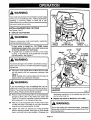
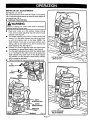
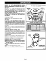
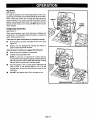
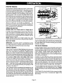
OWNER'S
MANUAL
MODEL NOS.
315.175040
315.175050
315.175060
CAUTION:
Read and follow
ALL safety rules
and instructions
before operating
this equipment.
MODEL NO. 315.175050
MODEL NO. 315.175060
CRRFTSMRNo
Router
Double Insulated
Thank You for Buying A
Craftsman Router
Warranty
Rules For Safe Operation
Table Of Contents
Introduction
Unpacking
SEARS, ROEBUCK AND CO., Hoffman Estates,
972000-248
7-00
Features
Operation
Accessories
Maintenance
Repair Parts
(_
IL 60179 U.S.A.
Printed in U.S.A.
FULL ONE YEAR WARRANTY
ON CRAFTSMAN
ROUTER
If this Craftsman Router fails to give complete satisfaction within one year from the date of purchase, RETURN IT
TO THE NEAREST SEARS STORE IN THE UNITED STATES, and Sears will repair it, free of charge.
If this Craftsman Router is used for commercial
date of purchase.
or rental purposes, this warranty applies for only 90 days from the
This warranty gives you specific legal rights, and you may also have other rights which vary from state to state.
Sears, Roebuck and Co., DEPT. 817 WA, Hoffman Estates, IL 60179
J
The purpose of safety symbols is to attract your attention to possible dangers. The safety symbols, and their
explanations with them, deserve your careful attention and understanding. The safety warnings do not by
themselves eliminate any danger. The instructions or warnings they give are not substitutes for proper accident
prevention measures.
SYMBOL
MEANING
i
A
SAFETY ALERT SYMBOL:
Indicates caution or warning. May be used in conjunction with other symbols or pictographs.
WARNING: Failure to obey a safety warning can result in serious injury to yourself or to others. Always
follow the safety precautions to reduce the risk of fire, electric shock and personal injury.
CAUTION: Failure to obey a safety warning may result in property damage or personal injury to yourself
or to others. Always follow the safety precautions to reduce the risk of fire, electric shock and personal
injury.
NOTE:
Advises you of information or instructions vital to the operation or maintenance of the equipment.
DOUBLE INSULATION is a safety concept in electric power
tools which eliminates the need for the usual three wire
grounded power cord and grounded supply system. Wherever
there is electric current in the tool there are two complete sets
of insulation to protect the user. All exposed metal parts are
isolated from internal metal motorcomponents with protecting
insulation.
ELECTRICAL
IMPORTANT - Servicing of a tool with double insulation
requires extreme care and knowledge of the system and
should be performed only by a qualified service technician.
For service we suggest you return the tool to your nearest
Sears Store for repair. Always'use originalfactory replacement
parts when servicing.
CONNECTION
Your router has a precision built electric motor. It should be connected to a power supply that is 120 volts, 60 Hz, AC only
(normal household current), Do not operate this tool on direct current (DC). A voltage drop of more than 10 percent will
cause a loss of power and the motor will overheat. If your tool does not operate when plugged into an outlet, double-check
the power supply.
L
,&
I
Look for this symbol to point out important
It means attention!!!
safety
Your safety is involved.
Page 2
precautions.
[
J
,WARNING:
WARNING:
Do not attempt to operate this tool until you have
read thoroughly
and understand
completely
all
instructions,
safety rules, etc. contained
in this
manual. Failure to comply can result in accidents
involving fire, electric shock, or serious personal
injury. Save owner's manual and review frequently
for continuing safe operation, and instructing others
who may use this tool.
The double insulated system is intended to protect the
user from shock resulting from a break in the tool's
internal wiring. Observe all normal safety precautions
related to avoiding electrical shock.
READ ALL INSTRUCTIONS
.
KNOW
YOUR
POWER
TOOL.
Read
GUARD AGAINST ELECTRICAL SHOCK by
preventing body contact with grounded surfaces.
For example: Pipes, radiators, ranges, refrigerator
enclosures.
3.
KEEP GUARDS
IN PLACE
4.
KEEP WORK AREA CLEAN.
and benches invite accidents.
5.
AVOID
DANGEROUS
ALWAYS WEAR SAFETY GLASSES. Everyday
eyeglasses
have only impact-resistant lenses;
they are NOT safety glasses.
12.
PROTECT
and in working order.
Cluttered
ENVIRONMENT.
KEEP CHILDREN
AND VISITORS
AWAY.
14.
DON'T ABUSE CORD. Never carry tool by cord
or yank it to disconnect
from receptacle. Keep
cord from heat, oil and sharp edges.
15.
SECURE WORK. Use clamps or a vise to hold
work. Both hands are needed to operate the tool.
16.
DON'T OVERREACH.
Keep proper footing and
balance at all times. Do not use on a ladder or
unstable support.
17.
MAINTAIN TOOLS WITH CARE. Keep tools
sharp at all times, and clean for best and safest
performance. Follow instructions for lubricating
and changing accessories.
18.
DISCONNECT TOOLS. When not in use, before
servicing, or when changing attachments, blades,
bits, cutters, etc., all tools should be disconnected
from power supply.
19.
REMOVE
All
visitors should wear safety glasses and be kept
a safe distance from work area. Do not let
visitors contact tool or extension cord.
.
STORE
IDLE
TOOLS.
When
not in use tools
should be stored in a dry and high or locked-up
place - out of the reach of children.
,
9.
10.
ADJUSTING
KEYS AND WRENCHES.
Form habit of checking to see that keys and
adjusting wrenches are" removed from tool be-
DON'T FORCE TOOL. It will do the job better
and safer at the rate for which it was designed.
USE RIGHT TOOL. Don't force small tool or
attachment to do the job of a heavy duty tool.
Don't use tool for purpose not intended - for
example - A circular saw should never be used
for cutting tree limbs or logs.
Wear a face or dust
PROTECT YOUR HEARING. Wear hearing
protection during extended periods of operation.
use power tool in damp or wet locations or expose
to rain. Keep work area well lit.
6.
LUNGS.
13.
areas
Don't
YOUR
mask if operation is dusty.
owner's
manual
carefully.
Learn its applications
and
limitations as well as the specific potential hazards
related to this tool.
.
11.
fore turning it on.
20.
AVOID
ACCIDENTAL
STARTING.
Don't carry
plugged-in tools with finger on switch. Be sure
switch is off when plugging in.
21.
WEAR PROPER APPAREL. Do not wear loose
clothing or jewelry that can get caught in tool's
moving parts and cause personal injury. Rubber
gloves and non-skid footwear are recommended
when working outdoors. Wear protective hair
covering to contain long hair and keep it from
being drawn into nearby air vents.
Page 3
MAKE
SURE
YOUR
EXTENSION
CORD
IS IN
GOOD CONDITION.
When using an extension
cord, be sure to use one heavy enough to carry the
current your product will draw. An undersized cord
will cause a drop in line voltage resulting in loss of
power and overheating. A wire gage size (A.W.G.)
of at least 14 is recommended for an extension
cord 100 feet or less in length. A cord exceeding
100 feet is not recommended. If in doubt, use the
next heavier gage. The smaller the gage number,
the heavier the cord.
RULES FOR SAFE OPERATION
22.
OUTDOOR
USE EXTENSION
(Continued)
CORDS. When tool
33.
is used outdoors, use only extension cords suitable
for use outdoors. Outdoor approved cords are
marked with the suffix W-A, for example - SJTW-A
or SdOW-A.
23.
KEEP CUTTERS
CLEAN
AND SHARP.
Sharp
KEEP HANDS
AWAY
FROM
CUTTING
35.
POLARIZED
INSPECT
TOOL
CORDS
INSPECT
CALLY
28.
KEEP
EXTENSION
CORDS
and
36.
DRY,
CLEAN,
37.
PERIODI-
AND
FREE
38.
STAY ALERT. Watch what you are doing and
use common sense. Do not operate tool when
you are tired. Do not rush.
30.
CHECK
PARTS.
Before further
binding of moving parts, breakage
of parts,
mounting, and any other conditions that may
affect its operation. A guard or other part that is
damaged should be properly repaired or replaced
32.
service center.
FOR and remove all nails from lumber
before routing.
USING
THIS
ROUTER
WITH
A
SAVE
THESE
INSTRUCTIONS.
Review
them
WARNING:
Some dust created by power sanding, sawing, g rinding,
drilling, and other construction
activities contains
chemicals known to cause cancer, birth defects or
other reproductive
harm. Some examples of these
chemicals are:
•.
• lead from lead-based
paints,
• crystalline silica from bricks and cement
and other masonry products, and
DO NOT USE TOOL IF SWITCH
DOES NOT
TURN IT ON AND OFF. Have defective switches
INSPECT
WHEN
frequently and use them to instruct others who
may use this tool. If you loan someone this tool,
loan them these instructions also.
by an authorized service center unless indicated
elsewhere in this instruction manual.
replaced by an authorized
"BROWN-OUT"
CONDITIONS.
use
of the tool, a guard or other part that is damaged
should be carefully checked to determine that it
will operate properly and perform its intended
function. Check for alignment of moving parts,
31.
DO NOT USE TOOL UNDER
OR OTHER
LOW VOLTAGE
CUTTER GUARDED
AT ALL TIMES. Use only
router tables, with guards, that have been designed for use on routers that are of this type,
size, and weight.
or any strong
29.
DAMAGED
of
ROUTER
TABLE,
HELP
PREVENT
POSSIBLE SERIOUS INJURY BY KEEPING THE
FROM OIL AND GREASE. Always use a clean
cloth when cleaning. Never use brake fluids,
gasoline, petroleum-based products
solvents to clean your tool.
the risk
Also, do not use with any device that could cause
the power supply voltage to change.
and rep,lace if damaged.
HANDLES
reduce
instatl the proper outlet. Do not change the plug
in any way.
if damaged, have repaired at your nearest Sears
Repair Center. Stay constantly
aware of cord
location.
27.
To
not fit fully in the outlet, reverse the plug. If it still
does not fit, contact a qualified electrician to
ATMOSPHERE.
PERIODICALLY
PLUGS.
electric shock, this tool has a polarized plug (one
blade is wider than the other). This plug will fit in
a polarized outlet only one way. If the plug does
AREA.
Normal sparking of the motor could ignite fumes.
26.
Do not
WHEN
SERVICING
USE ONLY IDENTICAL
CRAFTSMAN
REPLACEMENT
PARTS.
attempt to remove material while cutter is rotating.
NEVER USE IN AN EXPLOSIVE
MEDICATION.
34.
Keep hands away from cutters. Do not reach
underneath work while cutter is rotating. Do not
25.
ALCOHOL,
operate tool while under the influence of drugs,
alcohol, or any medication.
cutters minimize stalling and kickback.
24.
DRUGS,
• arsenic and chromium from chemicallytreated lumber.
Your risk from these exposures varies, depending on
how often you do this type of work. To reduce your
exposure to these chemicals: work in a well ventilated
area, and work with approved safety equipment, such '
as those dust masks that are specially designed to filter
out microscopic particles.
Page 4
•
Warranty
................................................
•
•
Rules For Safe Operation .................
Table Of Contents .................................
•
Introduction
2
2-4
5
and Product
Specifications
.......................................
•
Unpacking
•
Features ..............................................
Switch
..................................................
Lock-On Button .......................................
Force Feeding ......................................
Too Slow Feeding .................................
Depth Of Cut .........................................
Direction Of Feed and Thrust ...............
14
14
15
15
15
7
7
Routing ................................................
Starting and Ending A Cut
Internal Routing ...............................
7
Edging With Pilot Bits ...........................
Edge Routing ........................................
16
16
Routing With Guide Bushings ...............
Router Tables .......................................
17
17
6
.............................................
7
7-9
7
7
Chip Shield .............................................
Wrench Storage Area .............................
Variable Speed (Model Nos.
315.175050 and 315.175060 Only) ........
Dust Bag Assembly
(Model No. 315.175060 Only) ................
To Install Dust Bag ............................
To Empty Du_ Bag ...........................
Know Your Router ..................................
Model No. 315.175040 ......................
Model No. 315.175050 ......................
Model No. 315.175060 ......................
•
Proper Feeding .....................................
14
Speed Selections (Model Noso
315.175050 and 315.175060 Only) ...... 14
Rate Of Feed ........................................
14
7
7
7
8
8
9
9
•
Switch
Operation ........................................
10-17
Installing/Removing Cutters .................. 10
Depth Of Cut Adjustments ....................
Depth Of Cut Adjustments When
Mounted To A Router Table .................
Maintenance
11
12
...................................
17-22
Replacement
(Model No. 315.175040) .......................
Switch Replacement
(Model Nos.
315.175050 and 315.175060)
..............
Light Bulb Replacement
.......................
17
Proper Care Of Cutters .........................
Proper Care Of Collet ...........................
Lubrication ............................................
19
19
19
Helpful Hints .........................................
General ................................................
Extension Cords. ..................................
19
20
20
21
Variable Speed (Model Nos.
315. 175050 and 315.175060)
.............
Practice Before Actual Use ...................
12
12
•
Accessories
•
Exploded
Routing ................................................
Freehand Routing .................................
13
13
•
Parts Ordering
Page 5
16
........................................
18
19
View and Parts List ...... 22-27
/ Service .....................
t
j
28
Congratulations
and thank you for buying this
Craftsman router. It has been designed, engineered and
manufactured to provide you with Sears high standard of
dependability, ease of operation, and operator safety.
Properly cared for, it will give you years of rugged, troublefree performance.
Your router has many features for making routing operations
more pleasant and enjoyable. Safety, performance and
dependability have been given top priority in the design of
this router making it easy to maintain and operate.
CAUTION:
Carefully read through this entire owner's manual before
using your new router. Pay close attention to the Rules
For Safe Operation, Warnings and Cautions. If you use
your router properly and only for what it is intended, you
will enjoy years of safe, reliable service.
SPECIFICATIONS:
DEPTH
OF CUT
0 - 1-1/2 in.
COLLET
1/4 in.
HORSEPOWER
Model No. 315.175040
Model No. 315.175050
Model No. 315.175060
1-1/2
1-3/4
2
AMPS
Model No. 315.175040
Model No. 315.175050
Model No. 315.175060
8.0
8.5
9.0
RATING
120 volts, 60 Hz, AC only
NO LOAD SPEED
Model No. 315.175040
Model Nos. 315.175050 and 315.175060
25,000 RPM
15,000 - 25,000 RPM
POWER CORD
Model Nos. 315,175040 and 315.175050
Model No. 315.175060
6ft.
10ft.
DUSTLESS
Model No. 315.175060
NET WEIGHT
Model No. 315.175040
Model No. 315, t 75050
Model No. 315.175060
8.13 Ibs.
8.14 Ibs.
9 Ibs.
WARNING: ]
The operation of any router can result in foreign objects being thrown into your eyes, which
can result in severe eye damage. Before beginning power tool operation, always wear
safety goggles or safety glasses with side shields and a full face shield when needed. We
recommend Wide Vision Safety Mask for use over eyeglasses or standard safety glasses
with side shields, available at Sears Retail Stores.
Page 6
Your router has been shipped completely assembled and
ready for use. Inspect it carefully to make sure no breakage
or damage has occurred during shipping. If any parts are
damaged or missing, contact your nearest Sears Retail
Store to obtain replacement parts before attempting to
operate router. A wrench and this owner's manual are also
included.
WARNING:
If any parts are missing, do not operate your router until
the missing parts are replaced. Failure to do so could
result in possible serious personal injury.
SWITCH
To turn your router ON, depress the switch trigger, Release
switch trigger to turn your router OFF,
LOCK-ON
BUTTON
The switch of your router is equipped with a lock-on feature
which is convenient when operating for extended periods of
time. To lock on, depress the trigger, push in the lock button
located on the side of the handle_ then while holding the lock
button pushed in, release tke trigger. To release the lock,
depress the trigger and release it.
,WARNING:
Before connecting your router to power supply source,
always check to be sure it is not in lock-on position
(depress and release switch trigger). Failure to do so
could result in accidental starting of your router resulting
in possible serious injury. Also, do not lock the trigger on
jobs where your router may need to be stopped suddenly.
DUST BAG ASSEMBLY
(MODEL
A clear plastic chip shield is installed on the front of your
router for protection against flying dust and chips. The shield
is designed to fit the opening of the router base. If necessary
to remove chip shield, squeeze the tabs on each end and pull
outward. To replace, squeeze the tabs at each end, fit into
opening, then release. NOTE: Model No. 315.175060 has a
chip shield on the front and rear opening of the router base.
For your protection, do not use router without chip
shield(s) properly in place. If desired, the horsepower label
can be removed from chip shield by simply peeling off.
STORAGE
NO. 315.175060
ONLY)
See Figure lc.
The dust bag located on the side of your router provides a
dust collection system for your router. For more efficient
operation, empty dust bag when half full.
CHIP SHIELD
WRENCH
making proper speed selections, your router can be adjusted
to specific routing needs. This eliminates much of the guess
work previously needed to perform a given job. Both the
experienced
and inexperienced
router users benefit,
obtaining professional like results with fewer job errors.
The variable speed control allows the router speed to be
adjusted from 15,000 to 25,000 rpm. The variable speed
control selector is conveniently located outside the right
handle near the operator's thumb or hand.
Speed can be set according to the approximate cutter
diameter you wilt be using and to the hardness of the
material being cut. The best cuts are made when the cutter
is fed through material at the proper rate of feed.
AREA
Your router has a wrench storage area located on the top end
cap portion ofthe motor housing. When installing or removing
cutters, remove the wrench from its storage area. Proper
storage of wrench when not in use will help reduce the
Do not connect router to power supply before installing dust
bag or connecting it to a dust collection system.
WARNING:
To prevent the possibility of sb.wdust or foreign objects
being thrown into your face and eyes, never attempt to
use your router without dust bag properly installed.
Sawdust or foreign objects being thrown into your face or
eyes could result in possible serious injury.
TO INSTALL DUST BAG:
The dust bag should be installed by slipping it with a twisting
motion over the blower exhaust. The bag should be installed
with the zipper down when router is in upright position.
possibility of losing wrench.
TO EMPTY
VARIABLE
Remove dust bag from router, open zipper and shake out
dust. Occasionally turn the dust bag inside out and brush the
accumulation of dust from the inside of the bag. This will
SPEED SWITCH WITH ELECTRONIC
SPEED CONTROL
(MODEL
NOS. 315.175050
AND 315.175060
ONLY)
DUST
BAG:
allow the air to flow through the bag better.
See Figures lb and lc.
Your router has advanced electronic features, designed to
assist you in getting the maximum use from your router. By
Page 7
KNOW
YOUR
ROUTER
WARNING:
Before attempting to use your router, familiarize yourself with
all operating features and safety requirements. See Figure I.
Always wear
shields when
result in dust,
being thrown
injury.
WARNING:
Do not allow familiarity with your router to make you
careless. Remember that a careless fraction of a second
is sufficient to inflict severe injury.
safety goggles or safety glasses with side
operating your router. Failure to do so could
shavings, loose particles or foreign objects
into your eyes, causing possible serious
MODEL NO. 315.175040
UPSIDE DOWN VIEW OF ROUTER
DEPTH
INDICATOR
RiNG
INDICATOR
POINT
WRENCH
WRENCH
STORAGE
AREA
SPINDLE
POWER
HANDLE
SWITCH
HANDLE
BUTTON
LOCKING
KNOB
DEPTH
ADJUS_NG
RING
COLLETNUT'
CHIP SHIELD
DEPTH
INDICATORRING
INDICATOR
POINT
SUBBASE
Fig. la
Page 8
UPSIDE DOWN VIEW OF ROUTER
DEPTH
WRENCH
INDICATOR
POINT
RING
SPINDLE
WRENCH
STORAGE
AREA
POWER
HANDLE
SWITCH
HANDLE
TRIGGER_
LOCK-ON
BUTTON
LOCKING
KNOB
/ARIABLESPEED
CONTROLSELECTOR
DEPTH
ADJUSTING
RING
DEPTH
INDICATORRING
INDICATOR
CHIP SHIELD
WRENCH
SPINDLE
STORAGEAREA
SUBBASE
POINT MODEL NO, 315.175050
Fig, 1b
UPSIDE DOWN VIEW OF ROUTER
DEPTH
INDICATOR
RING
INDICATOR
POINT
WRENCH
BLOWER
MODEL NO. 315.175060
Page 9
WARNING:
_PINDL
LOCI_
Your router should never be connected to power supply
when you are assembling parts, making adjustments,
installing or removing cutters, or when not in use.
Disconnecting your router will prevent accidental starting
that could cause serious injury.
INSTALLING/REMOVING
\
CUTTERS
See Figures 2 and 3.
•
UNPLUG YOUR ROUTER.
WARNING:
Failure to unplug your router could result in accidental
starting causing serious injury.
<
TO LOCK
SPINDLE
If your router is Model No. 315.175060, before
installing/removing
cutters, you must remove one
of the chip shields from router base.
A spindle lock is located on the front of the motor
housing. To activate lock, push spindle lock in and slide
into lock position. See Figure 2.
PUSHIN TO
LOCKAND UNLOCK
CUTTER
TO UNLOCK
SPINDLE Fig. 2
COLLET
NUT
WRENCH
TO LOOSEN
COLLETNUT
WARNING:
To prevent damage to the spindle or spindle lock, always
allow motor to come to a complete stop before engaging
spindle lock.
PEaceyour router upside down on table, then turn collet
nut with wrench until lock mechanism interlocks. See
Figure 3.
NOTE: Spindle lock is spring loaded and will snap into
position when lock mechanism interlocks.
WARNING:
If you are changing a cutter immediately after use, be
careful not to touch the cutter or toilet with your hands or
fingers. They will get burned because of the heat buildup
from cutting. Always use the wrench provided.
I
•
Remove cutters by turning collet nut counterclockwise
enough to allow cutter to slip easily from collet. See
Figure 3. The collet is machined to precision tolerances
to fit cutters with 1/4 in. diameter shank size.
•
With your router still upside down on table, insert shank
of cutter into collet. The shank of your cutter should be
close to but not touching bottom of collet.
•
Tighten the collet nut securely by turning clockwise
with the wrench provided. See Figure 3. Push spindle
lock in and slide into unlock position. Otherwise, the
interlocking mechanism of the spindle lock will not let
you turn your router on.
•
Replace chip shield on Model No. 315.175060.
WARNING:
Do not use cutters with undersized shanks. Undersized
shanks will not tighten properly and could be thrown from
tool causing injury.
Page lO
DEPTH
OF CUT
ADJUSTMENTS
See Figures 4, 5, and 6.
We recommend that cuts be made at a depth not exceeding
1/8 in. and that several passes be made to reach depths of
cut greater than 1/8 in.
•
UNPLUG YOUR ROUTER,
[
,WARNING:
Failure to unplug your router could result in accidental
starting causing serious injury.
•
I
Place your router on a flat surface, loosen locking
knob, and turn depth adjusting ring until cutter is inside
subbase. See Figure 4.
Turn depth adjusting ring until tip of cutter touches flat
surface. Turn the depth indicator ring until the zero lines
up with the indicator point on the base. NOTE: The
depth indicator ring is also a zero reset indicator when
setting cutter at zero depth of cut, then it becomes the
depth adjusting ring. See Figure 5.
Position your router so _at the cutter can extend below
the subbase for desired depth setting. See Figure 6.
Turn the depth adjusting ring to obtain the desired depth
of cut. The distance the cutter moves can be read on the
•
•
•
depth indicator ring, Each mark on the depth indicator
ring indicates 1/16 inch change in depth setting. Indicator
point is located on the base.
Tighten locking knob securely before operating router.
•
DEPTH
ADJUSTINGRING
DEPTH
INDICATORRING
INDICATOR
CUTTER
INSIDE SUBBASE
i
' SUBBASE
Fig. 4
i
Page 11
CUTTERAT ZERO
DEPTHOF CUT
Fig. 5
DEPTH
OF
CUT
ROUTER
IS MOUNTED
ADJUSTMENTS
TO A ROUTER
WHEN
FOR ROUTERTABLE USEONLY
TABLE
See Figure 7.
DEPTH
INDICATORRING
The depth of cut is readable from both sides of the depth
indicator ring. The bottom ring is convenient when using
your router mounted upside down to a router table. The
indicator point on the base can also be used when using
your router mounted to a router table.
Set the cutter at zero depth of cut, rotate depth indicator ring
to desired depth of cut on the scale, then tighten locking
knob securely.
VARIABLE SPEED
(MODEL
NOS. 315.175050
AND 315.175060)
See Figure 8.
If your router is either one of these two models, it has a
variable speed control selector designed to allow operator
control of speed and torque limits, To increase the speed and
torque of your router, turn the variable speed control selector
to a higher setting. Turr_to a lower setting to decrease speed
and torque.
NOTE: If you do not want to use the variable speed control
selector, turn to the highest possible setting and the feature
will not be active.
PRACTICE
BEFORE
ACTUAL
MODELNOS. 315.175050AND 315.175060
W--"--"_'CUTTER
SIZE
USE
If your router is Model No. 315.175050 or 315.175060, we
suggest that you practice with the variable speed feature of
your router before installing a cutter and making cuts in
wood. Check the following before connecting your router
to power supply.
•
Make sure power supply is 120 volts, 60 Hz, AC only.
•
Make sure the spindle lock is in the unlocked position.
•
•
Make sure the trigger is not in the lock-on position.
Make sure there is not a cutter in the collet.
POWER
HANDLE
TO DECREASE
SPEEDANDTOROUE
[] Make sure the toilet does not extend below the subbase.
•
Choose the desired speed from the speed selection
chart. See Figure 8.
•
Turn the variable speed control selector to the desired
setting.
•
Plug your router into power supply source.
•
Grasp your router firmly with both hands and turn on.
TOINCREASE
SPEEDANDTORQUE
IABLESPEED
CONTROLSELECTOR
Fig. 8
ii
Page 12
ROUTING
See Figure 9.
For ease of operation and maintaining proper control, your
router has two handles, one on each side of the router base.
When using your router hold it firmty with both hands as
shown in figure 9. Turn router on and let motor build to its full
speed, then gradually feed cutter into workpiece. Remain
alert and watch what you are doing. DO NOT operate router
when fatigued.
FREEHAND
ROUTING
See Figure 10.
When used freehand, your router becomes a flexible and
versatile tool. This flexibility makes it possible to easily rout
signs, relief sculptures, etc.
There are two basic techniques
for freehand routing:
•
Routing letters, grooves, and patterns into wood. See
Figure 10.
•
Routing out the background, leaving the letters or
pattern raised above _e surface.
When freehand routing, we suggest the following:
•
Draw or layout the pattern on workpiece.
•
Choose the appropriate
cutter.
NOTE: A core box or V-groove bit is often used for
routing letters and engraving objects. Straight bits and
ball mills are often used to make relief carvings. Veining
bits are used to carve small, intricate details.
•
Rout the pattern in two or more passes. Make the first
pass at 25% of the desired depth of cut. This will
provide better control as well as being a guide for the
next pass.
•
DO NOT rout deeper than 1/8 in. per pass or cut.
Page13
PROPER
FEEDING
The right feed is neither too fast nor too slow. It is the rate at
which the bit is being advanced firmly and surely to produce
a continuous spiral of uniform chips --without hogging into
the wood to make large individual chips or, on the other hand,
to create only sawdust. If you are making a small diameter,
shallow groove in soft, dry wood, the proper feed may be
about as fast as you can travel your router along your guide
line. On the other hand, if the bit is a large one, the cut is deep
or the wood is hard to cut, the proper feed may be a very slow
one. Then, again, a cross-grain cut may require a slower
pace than an identical with grain cut in the same workpiece.
TOO FAST
There is no fixed rule. You will learn by experience..,
by
listening to the router motor and by feeling the progress of
each cut. If at all possible, always test a cut on a scrap piece
of the workpiece wood, beforehand.
SPEED
(MODEL
SELECTION
NOS. 315.175050
AND 315.175060
ONLY)
In general, if the material being cut is hard, the cutter size is
large, or the depth of cut i_ deep (maxim um 1/8 in.), then you r
router should be run at slower speeds. When these situations exist, turn the variable speed control selector until the
desired speed is reached.
NOTE: Carbide cutters cut at higher speeds than steel
cutters and should be used when cutting very hard materials.
TOO SLOW
Fig. 11
#
IMPORTANT: The whole "secret" of professional routing
and edge shaping lies in making a careful set-up for the cut
You can always detect "force feeding" by the sound of the
motor. Its high-pitched whine will sound lower and stronger
as it loses speed. Also, the strain of holding the tool will be
noticeably increased.
to be made and in selecting the proper rate of feed.
TOO SLOW
FORCEFEEDING
It is also possible to spoil a cut by moving the router forward
too slowly. When it is advanced into the work too slowly, a
revolving bit does not dig into new wood fast enough to take
a bite; instead, it simply scrapes away sawdust-like particles. Scraping produces heat, which can glaze, burn, or
mar the cut-- in extreme cases, can even overheat the bit so
RATE OF FEED
Clean, smooth routing and edge shaping can be done only
when the bit is revolving at a relatively high speed and is
taking very small bites to produce tiny, cleanly severed
chips. If your router is forced to move forward too fast, the
RPM of the bit becomes slower than normal in relation to its
forward movement. As a result, the bit must take bigger bites
as it revolves. "Bigger bites" mean bigger chips, and a
rougher finish. Bigger chips also require more power, which
could result in the router motor becoming overloaded.
Under extreme force-feeding conditions the
the bit can become so slow -- and the bites
large -- that chips will be partially knocked
fully cut off), with resulting splintering and
workpiece. See Figure 11.
relative RPM of
it has to take so
off (rather than
gouging of the
Your Craftsman Router is an extremely high-speed tool, and
will make clean, smooth cuts if allowed to run freely without
the overload of a forced (too fast) feed. Three things that
cause'force feeding" are bit size, depth-of-cut, and workpiece
characteristics. The larger the bit or the deeper the cut, the
more slowly the router should be moved forward. If the wood
is very hard, knotty, gummy or damp, the operation must be
slowed still more.
FEEDING
as to destroy its hardness.,
In addition, it is more difficult to control a router when the bit
is scraping instead of cutting. With practically no load on the
motor the bit will be revolving at close to top RPM, and will
have a much greater than normal tendency to bounce off the
sides of the cut (especially, if the wood has a pronounced
grain with hard and soft areas). As a result, the cut produced
may have rippled, instead of straight sides. See Figure 11.
"Too-slow feeding" can also cause your router to take off in
a wrong direction from the intended line of cut. Always
grasp and hold your router firmly with both hands when
routing.
You can detect "too-slow feeding" by the runaway too-highly
pitched sound of the motor; or by feeling the "wiggle" of the
bit in the cut.
Page 14
DEPTH
OF CUT
As previously mentioned, the depth of cut is important
because it affects the rate of feed which, in turn, affects the
quality of a cut (and, also, the possibility of damage to your
router motor and bit). A deep cut requires a slower feed than
a shallow one, and a too deep cut will cause you to slow the
feed so much that the bit is no longer cutting, it is scraping,
instead.
DEPTH
OF CUT
---_,
Iq_
WIDTH
r:l-°,cu,
Fig, 12
Making a deep cut is never advisable. The smaller bits -especially those only 1/16 inch in diameter -- are easily
broken off when subjected to too much side thrust. A large
enough bit may not be broken off, but if the cut is too deep a
rough cut will result--and it may be very difficult to guide and
control the bit as desired. For these reasons, we recommend
that you do not exceed 1/8 inch depth of cut in a single pass,
regardless of the bit size or the softness or condition of the
workpiece. See Figure 12.
2ND.
PASS
1ST.
PASS
2ND. PASS
To make deeper cuts it is therefore necessary to make as
many successive passes as required, lowering the bit 1/8
inch for each new pass. Ir_.order to save time, do all the
cutting necessary at one depth setting, before lowering the
bit for the next pass. This will also assure a uniform depth
when the final pass is completed. See Figure 13.
DIRECTION
OF FEED AND THRUST
The router motor and bit revolve in a clockwise direction. This
gives the tool a slight tendency to twist (in your hands) in a
counterclockwise direction, especially when the motor is
starting up.
Because of the extremely high speed of bit rotation during a
"proper feeding" operation, there is very little kickback to
contend with under normal conditions. However, should the
bit strike a knot, hard grain, foreign object, etc. that would
affect the normal progress of the cutting action, there will be
a slight kickback-- sufficient to spoil the trueness of you r cut
if you are not prepared. Such a kickback is always in the
direction opposite to the direction of bit rotation.
To guard against such a kickback, plan your set-up and
direction of feed so that you will always be thrusting the tool
-- to hold it against whatever you are using to guide the cut
-- in the same direction that the leading edge of the bit is
moving. In short, the thrust should be in a direction that keeps
the sharp edges of the bit continuously biting straight into
new (uncut) wood.
THRUST'J
GUIDE INSIDE
Fig. 14
=d
la
ROUTING
FEED
'_'
Whenever you are routing a groove, your travel should be in
a direction that places whatever guide you are using at the
right-hand side. In short, when the guide is positioned as
shown in the first part of Figure 14, tool travel should be left
to right and counterclockwise
around curves. When the
guide is positioned as shown in the second part of Figure 14
tool travel should be right to left and clockwise around
curves. If there is a choice, the first set-up is generally the
easiest to use. In either case, the sideways thrust you use is
against the guide.
Page 15
STARTING
AND ENDING
A CUT
INTERNAL ROUTING
ROUTER
Tilt router and place on workpiece, letting edge of subbase
contact workpiece first. Be careful not to let router bit contact
workpiece. Turn router on and let motor build to its full speed.
Gradually feed cutter into workpiece until subbase is level
with workpiece.
WORK
WARNING:
PILOT
Keep a firm grip on router with both hands at all times.
Failure to do so could result in loss of control leading to
possible serious injury.
TOPEDGESHAPING
Upon completion of cut, turn motor off and let it come to a
complete stop before removing router from work surface.
ROUTER
GUIDE
WORK
T
WARNING:
Never pull router out of work and place upside down on
work surface before the cutter stops.
EDGING WITH PILOT BITS
The arbor-type bits with pilots are excellent for quick, easy,
edge shaping of any workpiece edge that is either straight or
curved at a curvature as great or greater than the radius of
the bit to be used. The pilot prevents the bit from making too
deep a cut; and holding the pilot firmly in contact with the
workpiece edge throughout prevents the cut from becoming
too shallow.
Whenever the wo rkpiece thickness together with the desired
depth of cut (as adjusted by router depth setting) are such
that only the top part of the edge is to be shaped (leaving at
least a 1/16 inch thick uncut portion at bottom), the pilot can
ride against the uncut portion, which will serve to guide it.
See Figure 15. However, if the workpiece is too thin or the
bit set too low so that there will be no uncut edge to ride the
pilot against, an extra board to act as a guide must be placed
under the workpiece. This "guide" board must have exactly
the same contour -- straight or curved -- as the workpiece
edge. If it is positioned so that its edge is flush with the
workpiece edge, the bit will make a full cut (in as far as the
bit radius). On the other hand, if the guide is positioned as
shown in Figure 15 (out from the workpiece edge), the bit will
make less than a full cut -- which will alter the shape of the
finished edge.
NOTE: Any of the piloted bits can be used without a pilot for
edge shaping with guides, as preceding. The size (diameter)
of the pilot that is used determines the maximum cut width
that can be made with the pilot against the workpiece edge
(the small pilot exposes all of the bit; the large one reduces
this amount by 1/16 inch).
WHOLE
EDGE SHAPING
Fig. 15
EDGE ROUTING
Place router on workpiece, making sure the router bit does
not contact workpiece. Turn router on and let motor build to
its full speed. Begin your cut, gradually feeding cutter into
workpiece.
WARNING:
Keep a firm grip on router With both hands at all times.
Failure to do so could result in loss of control leading to
possible serious injury.
Upon completion of cut, turn motor off and let it come to a
complete stop before removing router from work surface.
WARNING:
Never pull router out of work and place upside down on
work surface before the cutter stops.
h
Page 16
ROUTING WITH GUIDE BUSHINGS
ROUTER TABLES
When using the Template Guide Bushings Item No. 9-25082
with your router, you must visually center the bit with the
bushing before beginning your cut. You r router subbase may
be adjusted by loosening the screws holding the subbase to
your router. Be sure clamping lever is locked before centering bit in bushing. After centering bit with bushing, tighten
screws firmly.
The use of Craftsman routers on router tables offered by
other manufacturers has not been investigated for compliance with applicable safety standards.
WARNING:
Do not use with router tables that fail to conform to safe
wood working practices and offer proper guarding for the
cutter. Failure to comply can result in an accident causing
possible serious injury.
WARNING:
Failure to center bit with bushing or to firmly tighten
screws after centering could cause bit to come in contact
with bushing resulting in serious injury.
i
SWITCH
REPLACEMENT
(MODEL NO. 315.175040)
See Figures 16and 17.
•
UNPLUG YOUR ROUTER.
A
WARNING:
Failure to unplug your router could result in accidental
starting causing serious injury.
Remove screws (A) and handle cover (B). See Figure
16.
Note the location of the molded bend relief (C) on
the power handle cord. Also note all wiring in the
handle and how each lead is connected to the
switch. Connections
and wiring position must be
identical when installing new switch. See Figure 16.
Fig. 16
Remove leads from switch (D) by inserting a 1/32 in.
diameter nail or pin into switch lead receptacle and
pulling on lead as shown in figure 17. Remove nail or
pin with a twisting, pulling motion.
Make lead connections to new switch. Push each lead
as far as possible into proper switch receptacle. Pull on
leads to check lead connections with lead receptacles.
Locate switch in handle and place leads so they won't
be pinched or contact screws when handle cover is
replaced.
Make sure molded bend relief (C) is correctly positioned
in switch handle, then replace handle cover and screws.
Tighten all screws securely.
Page 17
SWITCH
1/32IN. DIAMETER
NAIL OR PIN
SWITCH
REPLACEMENT
(CONTINUED)
(MODEL NOS. 315.175050
AND 315.175060)
See Figures 18 and 19.
•
UNPLUG YOUR ROUTER.
c
D
Failure to unplug your router could result in accidental
starting causing serious injury.
WARNING:
1
Remove screws (A) and handle cover (B l, See Figure
18.
Note the location of the molded bend relief (C) on
the power handle cord. Also note all wiring in the
handle and how each lead is connected to the
switch, Connections and wiring position must be
identical when installing new switch. See Figure 18.
•
Remove leads from switch (D) by inserting a 1/32 in.
diameter nail or pin into switch lead receptacle and
pulling on lead as sRown in figure 19. Remove nail or
pin with a twisting, pulling motion.
•
Make lead connections to new switch. Push each lead
as far as possible into proper switch receptacle. Pull on
leads to check lead connections with lead receptacles.
•
Locate switch in handle and place leads so they won't
be pinched or contact screws when handle cover is
replaced.
•
Make sure molded bend relief (C) is correctly positioned
in switch handle, then replace handle cover and screws.
•
Tighten all screws securely.
Fig. 18
VIOLET
VARIABLE
SPEED
Fig. 19
Page 18
LIGHT
BULB
REPLACEMENT
See Figure20.
•
UNPLUG YOUR ROUTER.
WARNING:
Failure to unplug your router could result in accidental
starting causing serious injury.
I
•
Remove cutter from router.
•
Adjust router to maximum height.
•
Remove screws (A) and subbase (B). See Figure 20.
•
Remove screw (C) and work light lens (D).
•
With bulb (E) pointing toward you, push bulb in and
turn to the left to remove from bulb socket.
NOTE: Light bulb removal and installation is similar to
removing and installing a standard automotive bulb.
•
Install new bulb by reversing the above procedure.
•
Reassemble all parts and tighten screws securely.
PROPER
CARE OF CUTTERS
PROPER
Get faster and more accurate cutting results by keeping
cutters clean and sharp. Remove all accumulated pitch and
gum from cutters after each use.
A cutter sharpening kit (item No. 9-66501) is available from
Sears Retail Stores.
When sharpening cutters, sharpen only the inside of the
cutting edge. Never grind the outside diameter. Be sure
when sharpening the end of a cutter to grind the clearance
angle the same as originally ground.
HELPFUL
•/
CARE OF COLLET
From time to time, it also becomes necessary to clean your
collet and collet nut. To do so, simply remove collet nut from
collet and clean the dust and chips that have collected. Then
return eollet nut to its original position.
LUBRICATION
All of the bearings in this tool are lubricated with a sufficient
amount of high grade lubricant for the life of the unit under
normal operating conditions. Therefore, no further lubrication
is required.
HINTS
Always clamp workpiece securely before routing.
J A safe operator is one who thinks ahead.
J Always wear eye protection when routing.
J Make set-up adjustments carefully. Then double check. Measure twice and cut once.
J Keep cutters clean and properly sharpened.
,/ Don't let familiarity make you careless.
J Study all safety rules and do the job safely.
J NEVER place your hands in jeopardy.
J Make certain clamps can't loosen while in use.
,/ Test difficult set-ups on scrap -- Don't waste lumber.
,/ Plan each operation before you begin.
J Clean your router frequently. This will provide smoother operation of depth adjusting ring and locking knob areas.
J
Shake router or blow with an air jet to remove sawdust build-up.
THINK SAFETY BY THINKING AHEAD.
Page 19
WARNING:
WARNING:
When servicing use only identical Craftsman replacement
pads. Use of any other parts may create a hazard or
cause product damage.
i
GENERAL
EXTENSION
Only the parts shown on parts list, pages 23, 25 and 27 are
intended to be repaired or replaced bythe customer. All other
parts represent an important part of the double insulation
system and should be serviced only by a qualified Sears
service technician.
The use of any extension cord will cause some loss of power.
To keep the loss to a minimum and to prevent tool overheating,
use an extefision cord that is heavy enough to carry the
current the tool will draw.
Avoid using solvents when cleaning plastic parts. Most
plastics are susceptible to damage from various types of
commercial solvents and may be damaged by their use. Use
clean cloths to remove dirt, carbon dust, etc.
an extension cord 100 feet or less in length. When working
outdoors, use an extension cord that is suitable for outdoor
use. The cord's jacket will be marked WA.
CORDS
A wire gage size (A.W.G.) of at least 14 is recommended for
CAUTION:
WARNING:
Keep extension cords away from any routing area and
3osition the cord so that it will not get caught on lumber,
tools, etc., during routing operation.
Do not at any time let brake fluids, gasoline, petroleum.
based products, penetrating oils, etc. come in contact
with plastic parts. They contain chemicals that can
damage, weaken, or destroy plastic.
I
I
When electric tools are used on fiberglass boats, sports cars,
wallboard, spackling compounds, or plaster, it has been
found that they are subject to accelerated wear and possible
premature failure, as the fiberglass chips and grindings are
highly abrasive to bearings, brushes, commutators, etc.
Consequently it is not recommended that this tool be used for
extende_ work on any fiberglass material, wallboard,
spackling compounds, or plaster. During any use on these
materials, it is extremely important that the tool is cleaned
frequently by blowing with an air jet.
Page 20
WARNING:
THE FOLLOWING
RECOMMENDED
ACCESSORIES
ARE
CURRENTLY
AVAILABLE AT SEARS RETAIL STORES.
Dovetail Template
Rout - A- Form Pantograph
Box Joint Template
Sharpening Kit
Butt Hinge Template
Multi-Purpose Router Guide
=
HINGE DOVETAILRABBET OGEE,
COVE
BEAD IARBOR
COMBI- VEINING CORE BOX STRAIGHT COMBBIT
FACE
INATION
MORTISING
CUTTER
BIT'
:rOMANC
BIT,
QUARTER2589
NATION
BIT
BIT
STRAIGHT
BIT
BITS
45°
PANEL
BEVEL
CHAMFER ROUND
BITS
CUTTER
I
BIT
CUTTER
I"
t
V-GROOVE
CHAMFER
LI
WITH2
BALL
3EARINGS
(1/2IN,&
G/_iN.)
"2G89G
I
I
*CARBIDETIPPEDBITS
I
I
*25895FOR CARBIDETIPPEDEDGEFORMINGBITS
2589 FOR HIGHSPEEDSTEEL EDGEFORMINGBITS
...._i_!v_i_
¸ _ i_i_'_i_i_i_i_ii!i_i!i_iiiiiii_i!_ii!_i_Ti_ii_i_i_i_ii
i_i!_
/!i
_i_;_!
_
"i
i _!iii_!!i!!!_!!_!_!!!_!_!i_!!ii!!!
ii_
i
i
WARNING:
The use of attachments or accessories
Page 21
not listed above might be hazardous.
_i_
CRAFTSMAN
ROUTER - MODEL NUMBER
315.175040
NOTE "A"
NOTE: "A" - The assembly shown represents an important part of the Double Insulated System. To avoid the
possibility of alteration or damage to the System, service should be performed by your nearest Sears
Repair Center. Contact your nearest Sears Retail Store for Service Center information.
Page 22
CRAFTSMAN
I
ROUTER - MODEL NUMBER
315.175040
in all correspondence regarding your ROUTER or when ordering repair parts.
Themodelnumberwillbefoundonaplateattachedtothemotorhousing.
Always mention the model number
SEE BACK
PAGE FOR PARTS
ORDERING
INSTRUCTIONS
PARTS LIST
Key
No.
Part
Number
1
973741-001
Data Plate .........................................
2
970692-001
Label ......................................................................................................
1
3
989985-003
Collet Nut (1/4 in.) .................................................................................
1
4
974722-000
Depth Adjusting Ring Assembly (Includes Key No. 24) ......................... 1
5
974131-001
Depth Indicator Ring .............................................................................
1
6
623166-008
* Square Head Bolt (#1/4-20 x 1-1/4 in,) ..................................................
1
7
622832-014
Roll Pin ...................................................................................................
1
8
606066-004
* Screw (#10-32 x 3/4 in. Pan Hd.) ..........................................................
4
Description
Quan.
_...................................................
1
9
617986-030
* Screw (#8-10 x 5/8 in, Pan Hd.) ............................................................
8
10
970697-000
Handle Assembly ..................................................................................
1
11
973735-002
Base .......................................................................................................
1
12
608688-002
Chip Shield ............................................................................................
1
13
998586-001
* Screw (#10-32 x 1/4 in, Pan Hd.) ..........................................................
3
14
612191-004
Subbase .................................................................................................
1
15
989684-001
* Screw (#6-32 x 1/4 in. T.C, Pan Hd,) ....................................................
1
16
975041-001
Work Light Lens ....................................................................................
1
17
610930-002
Light Housing ........................................................................................
1
18
970596-000
Power Handle Assembly .......................................................................
1
19
610951-001
Light Bulb ..............................................................................................
1
20
998895-001
Switch ....................................................................................................
1
21
623173-006
Wire Nut ....................................................................
22
999603-001
Knob .......................................................................................................
1
23
931744-059
Washer ...................................................................................................
3
24
970855-001
* Screw (#5-20 x 3/8 in. Hi-Lo Fil. Hd,) ....................................................
2
25
989935-006
Wrench (9/16 in.) ..................................................................................
1
972000-248
Owner's Manual
* Standard Hardware Item - May Be Purchased Locally
Page 23
L: ......................... 1
}
CRAFTSMAN
ROUTER - MODEL NUMBER
315.175050
SEE NOTE"A"
NOTE: "A" - The assembly shown represents an important part of the Double Insulated System. To avoid the
possibility of alteration or damage to the System, service should be performed by your nearest Sears
Repair Center. Contact your nearest Sears Retail Store for Service Center information.
Page 24
CRAFTSMAN
I
ROUTER - MODEL NUMBER
315.175050
in all correspondence regarding your ROUTER or when ordering repair parts.
Themodelnumberwillbefoundonaplateattachedtothemotorhousing.
Alwaysmentionthemodelnumber
SEE BACK
PAGE FOR PARTS
ORDERING
I
INSTRUCTIONS
PARTS LIST
Key
No.
Part
Number
1
973742-001
Data Plate .............................................................................................
1
2
970692-001
Label ......................................................................................................
1
3
969985-003
Collet Nut (1/4 in.) .................................................................................
1
4
974722-000
Depth Adjusting Ring Assembly (Includes Key No. 27) ......................... 1
5
974131-001
Depth Indicator Ring .............................................................................
1
6
623166-006
* Square Head Bolt (#1/4-20 x 1-1/4 in.) ..................................................
1
7
622832-014
Roll Pin ...................................................................................................
1
8
606066-004
* Screw (#10-32 x 3/4 in. Pan Hd.) ..........................................................
4
9
617966-030
* Screw (#8-10 x 5/8 in. Pan Hd.) ............................................................
8
10
970697-000
Handle Assembly ..................................................................................
1
11
973735-002
Base .......................................................................................................
1
12
606688-002
Chip Shield ............................................................................................
1
13
998586-001
* Screw (#10-32 x 1/4 in. Pan Hd.) ..........................................................
3
14
612191-004
Subbase .................................................................................................
1
15
989684-001
* Screw (#6-32 x 1/4 in. T.C. Pan Hd.) ....................................................
1
16
975041-001
Work Light Lens ....................................................................................
1
17
990822-002
Variable Speed Control Selector ...........................................................
1
18
610930-002
Light Housing ........................................................................................
1
19
970793-007
Red Lead ..............................................................................................
1
20
970793-008
Red Lead ..............................................................................................
1
21
970698-000
Power Handle Assembly ...........................................
22
623173-006
Wire Nut .................................................................................................
1
23
998895-002
Switch ....................................................................................................
1
24
610951-001
Light Bulb ..............................................................................................
1
25
999603-001
Knob .......................................................................................................
1
26
931744-059
Washer ...................................................................................................
3
27
970855-001
* Screw (#5-20 x 3/8 in. Hi-Lo Fil. Hd.) ....................................................
2
28
989935-006
Wrench (9/16 in.) ..................................................................................
1
972000-248
Owner's Manual
Description
Quan.
* Standard Hardware Item - May Be Purchased Locally
Page 25
.,............................ 1
CRAFTSMAN
ROUTER - MODEL NUMBER 315.175060
35
33
20
j4
17
I
NOTE: "A"-The
SEE NOTE "A"j
assembly shown represents an important part of the Double Insulated System. To avoid the possibility of alteration or damage to the system,
service should be performed by your nearest Sears Repair Center. Contact your nearest Sears Retail Store for Service Center information.
Page 26
CRAFTSMAN
ROUTER - MODEL NUMBER
315.175060
The
ROUTER
modelornumber
when ordering
will be found
repaironparts,
a plato attached to the motor housing. Always mention the model number in all correspondence
SEE BACK PAGE FOR PARTS
ORDERING
regarding your
I
INSTRUCTIONS
PARTS LIST
Key
No.
Part
Number
Description
Quan.
Key
No.
PaM
Number
Description
Quan.
1
989985-003
Collet Nut (1/4 in.) .........................................
1
19
973735-204
Base ..............................................................
1
2
970692-002
Label .............................................................
1
20
606688-002
Chip Shield ...................................................
2
3
607433-003
Spacer ...........................................................
1
21
998586-001
4
610958-001
Blower ...........................................................
1
22
612191-004
5
970517-004
End Cap ........................................................
1
23
989684-001
6
617966-031
* Screw (#8-10 x 3/4 in. Pan Hd.) .................... 3
24
975041-001
Work Light Lens ............................................
7
622931-007
* Screw (#6-32 x 1-5116 in. Fil. Hd.) ................ 1
25
990822-002
Variable Speed Control Selector .................. 1
8
973743-001
1
26
610930-002
1
27
970793-007
Light Housing ................................................
Red Lead ......................................................
1
1
..................... 1
28
970793-008
Red Lead ......................................................
1
29
970698-000
Power Handle Assembly ...............................
1
9
989935-006
10
706404-004
11
974722-000
Data Plate .....................................................
Wrench (9/16 in.) ..........................................
* Hex Nut (#6-32) **STD541006
Depth Adjusting Ring Assembly
* Screw (#10-32 x 1/4 in. Pan Hd.) .................. 3
Subbase ........................................................
1
* Screw (#6-32 x 1/4 in. T.C, Pan Hd.) ............ 1
1
(Includes Key No. 35) ...................................
1
30
610951-001
Light Bulb .._...................................................
1
12
610966-002
Vacuum Hose ...............................................
1
31
998895-002
Switch ...........................................................
1
13
974131-001
Depth Indicator Ring .....................................
1
32
999603-001
Knob ..............................................................
1
14
623166-006
* Square Head Bolt (#1/4-20 x 1-1/4 in.) ......... 1
33
931744-059
Washer ..........................................................
3
15
622832-014
1
34
623173-006
Wire Nut ........................................................
1
16
606066-004
* Screw (#10-32 x 314 in. Pan Hd,) .................. 4
35
970855-001
17
617966-030
* Screw (#8-10 x 5/8 in. Pan Hd.) .................... 8
36
971788-003
Dust Bag Assembly ......................................
18
970699-000
972000-248
Owner's Manual
Roll Pin ................. :;.......................................
Handle Assembly ..........................................
1
* Standard Hardware Item -- May Be Purchased Locally
Page 27
* Screw (#5-20 x 3/8 in. Hi-Lo FiL Hd.) ............ 2
** Available From DIv.98 -- Source 980.00
1
For repair of major brand appliances in your own home...
no matter who made it, no matter who sold it!
1-800-4-MY-HOME
sMAnytime,
day or night
(1-800-469-4663)
www.sears.com
To bring in products such as vacuums, lawn equipment and electronics
for repair, call for the location of your nearest Sears Parts & Repair Center.
1-800-488-1222
Anytime,
day or night
p,
www.sears.com
For the replacement parts, accessories and owner's manuals
that you need to do-it-yourself, call Sears PartsDirect sM!
1-800-366-PART
(1-800-366-7278)
6 a.m.-
11 p.m. CST,
7 days a week
www.sears.condpartsdirect
To purchase or inquire about a Sears Service Agreement:
1-800-827-6655
7 a.m.-
5 p.m. CST, Mon.-
Para pedir servicio de reparacibn a domicilio,
y para ordenar piezas con entrega a domicilio:
1-888-SU-HOGAR
sM
Sat.
''
Au Canada
pour service
(1-877-533-6937)
(1-888-784-6427)
HomeCentral
SEARS °°}
® Registered Trademark / TMTrademark of Sears, ROebuck and Co.
© Sears, Roebuck
and CO.
® Marca Registrada / TM Mama de Fdbrica de Sears, Roebuck
en fran_ais:
1"877"LE'FOYERS"
and Co.