1
OpenCV Provider User’s Guide
-1-
OpenCV provider
DENSO robot vision
(DENSO Robot Imaging Library)
Version 1.5.4
User's guide
February 25, 2015
ORiN Forum
DENSO WAVE Inc.
OpenCV Provider User’s Guide
-2-
ATTENTION:
DENSO WAVE doesn’t assume the responsibility of any problems caused by the mistranslation of this
document.
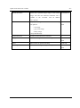
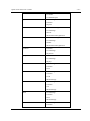
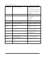
【Revision History】
Version
Date
Content
1.0.0.0
2007-01-30
First edition.
1.0.1.0
2007-04-06
Added several OpenCV commands; OcvTester bugs fixed.
1.1.0.0
2007-08-06
Added several new commands for pattern matching; the start image ID was
changed from 0 to 1.
1.2.0.0
2007-11-21
Added triangulation functions and several OpenCV commands.
1.2.1.0
2007-12-05
Improve the camera setting functions; Added blob commands.
1.2.2.0
2008-02-06
Added put/get commands of a video control mode, ‘Database’ option, and
Error table.
1.3.0.0
2008-02-29
Added Inner and Outer product commands.
1.3.1.0
2008-05-07
Added Blob commands. Improve MatchTemplate functions.
1.3.2.0
2008-09-17
Added Trim commands. Improve MatchTemplate2, MatchShapes2 and
Undistort2 functions.
1.3.3.0
2009-01-20
Added Blob commands, calibration wizard to OcvTester, message transfer
function and default camera function.
1.3.4.0
2009-06-03
Added several commands of the CaoController::Execute method.
1.3.5.0
2009-10-07
Added various commands, unify the rotation direction for all commands,
eliminate CamShit command, error code, and sample program.
1.4.0.0
2010-7-01
Mounting of CaoController::get_VariableNames.
1.4.1.0
2010-11-02
Append a camera ID parameter to camera calibration commands.
1.4.1.1
2011-06-13
Added the capture screen.
ORiN Forum
DENSO WAVE Inc.
OpenCV Provider User’s Guide
-3-
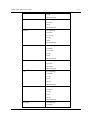
1.4.2.0
2012-01-11
Added various commands. Correct SetRobCalDat.
1.4.2
2012-07-17
Document versioning rule was changed.
1.4.3
2012-09-06
Added the recovery function of the database file (mdb).
2012-09-20
Added direction for “SetCameraCtrl”.
2012-10-23
Added commands.
1.4.4
“GetCameraFormatList”, “GetCameraFormat”, “SetCameraFormat”
1.4.5
2012-12-05
[Bug Fix] Memory leak in message transfer function.
2013-03-13
Added various commands.
SetCameraFrameRate, GetCameraFrameRate, IsUpdated, ClearUpdated
2013-04-01
Added Original Error Code.
Mounting of CaoFile::get_Attribute.
2013-06-26
Add CaoWorkspace::AddController method option
FrameRate
1.5.0
2013-07-22
Added FrameRate option and extended camera function
Change name:
OriN Vision > DENSO Robot Imaging Library
Correct BlobMatchShapes.
2013-09-24
Added CARD commands.
1.5.1
2013-11-18
Added extended camera commands.
1.5.2
2014-05-27
Added CARD commands.
Added extended camera commands.
Canon WebView Livescope camera correspondence.
1.5.3
2014-10-01
Added CARD commands.
1.5.4
2015-02-25
[Bug Fix] ADO
Change error code.
ORiN Forum
DENSO WAVE Inc.
OpenCV Provider User’s Guide
-4-
【Hardware】
Model
Version
Notes
【Attention】
Additional license for " DENSO Robot Imaging Library " is required to use this provider.
ORiN Forum
DENSO WAVE Inc.
OpenCV Provider User’s Guide
-5-
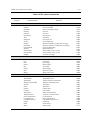
Contents
1. Introduction.............................................................................................. 8
1.1. Installing license ........................................................................................................................9
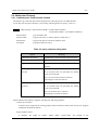
2. Outline of provider ................................................................................. 10
2.1. Outline.....................................................................................................................................10
2.1.1. Image memory..................................................................................................................13
2.1.2. Calibration ........................................................................................................................13
2.1.3. Triangulation .....................................................................................................................19
2.1.4. Message transfer function ................................................................................................21
2.2. Method and Property...............................................................................................................22
2.2.1. CaoWorkspace::AddController method ............................................................................22
2.2.2. CaoController::AddCommand method..............................................................................23
2.2.3. CaoController::AddFile method ........................................................................................23
2.2.4. CaoController::AddVariable method .................................................................................23
2.2.5. CaoController::Execute ....................................................................................................23
2.2.6. CaoController::get_VariableNames property ....................................................................24
2.2.7. CaoCommand::Execute method.......................................................................................24
2.2.8. CaoCommand::put_Parameter property ...........................................................................24
2.2.9. CaoCommand::get_Parameter property ...........................................................................24
2.2.10. CaoCommand::get_Result property ...............................................................................24
2.2.11. CaoFile::Execute method ...............................................................................................24
2.2.12. CaoFile::get_Attribute property .......................................................................................24
2.2.13. CaoFile::put_ID property ................................................................................................25
2.2.14. CaoFile::get_ID property ................................................................................................25
2.2.15. CaoFile::get_DateLastModified property ........................................................................25
2.2.16. CaoFile::Get_Size property ............................................................................................25
2.2.17. CaoFile::put_Value property ...........................................................................................25
2.2.18. CaoFile::get_Value property ...........................................................................................25
2.2.19. CaoFile::get_Help property .............................................................................................25
2.2.20. CaoController::OnMessage event ..................................................................................25
2.3. Variable list ..............................................................................................................................26
2.3.1. Controller class .................................................................................................................26
2.3.2. File class ..........................................................................................................................26
2.4. Error code ...............................................................................................................................27
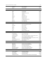
3. Sample program .................................................................................... 28
3.1. CaoScript sample program .....................................................................................................28
3.2. Other sample programs ..........................................................................................................28
ORiN Forum
DENSO WAVE Inc.
OpenCV Provider User’s Guide
-6-
4. Command Reference ............................................................................ 30
4.1. Controller class .......................................................................................................................35
4.1.1. Video setting .....................................................................................................................35
4.2. File class .................................................................................................................................46
4.2.1. General .............................................................................................................................46
4.2.2. Edit ...................................................................................................................................53
4.2.3. Filter .................................................................................................................................58
4.2.4. Mask .................................................................................................................................73
4.2.5. Draw .................................................................................................................................79
4.2.6. Contours ...........................................................................................................................86
4.2.7. Blob ..................................................................................................................................92
4.2.8. Histogram .........................................................................................................................99
4.2.9. Matching .........................................................................................................................102
4.2.10. CARD ...........................................................................................................................109
4.2.11. CAL ............................................................................................................................... 112
4.2.12. Misc. .............................................................................................................................128
4.3. Command class ....................................................................................................................138
4.3.1. Triangulation ...................................................................................................................138
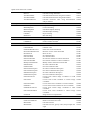
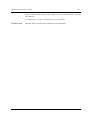
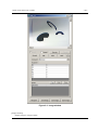
5. OcvTester .............................................................................................144
5.1. Outline...................................................................................................................................144
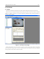
5.2. Main screen ..........................................................................................................................145
5.2.1. Object window ................................................................................................................145
5.2.2. Log window ....................................................................................................................145
5.2.3. Menu ..............................................................................................................................146
5.3. Image window .......................................................................................................................148
5.4. DENSO Robot connection window .......................................................................................151
5.5. Camera Settings window ......................................................................................................153
5.6. Triangulation window.............................................................................................................153
5.7. Calibration Wizard .................................................................................................................155
5.7.1. Overview ........................................................................................................................155
5.7.2. Step 0: Select calibration target ......................................................................................156
5.7.3. Step 1 : Set camera calibration parameter .....................................................................157
5.7.4. Step 2 : Acquire chessboard image ................................................................................158
5.7.5. Step 3 : Map world coordinate and robot coordinate ......................................................159
5.7.6. Step 4 : Comlete Wizard .................................................................................................160
5.8. Lookup table editor ...............................................................................................................160
5.9. Image sampling window ........................................................................................................161
ORiN Forum
DENSO WAVE Inc.
OpenCV Provider User’s Guide
-7-
5.10. Haar training window...........................................................................................................163
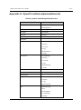
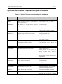
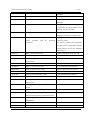
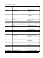
Appendix A. OpenCV method implementation list ....................................166
Appendix B. uVision21 equivalent OpenCV method ................................181
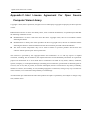
Appendix C. Intel License Agreement For Open Source Computer Vision
Library ......................................................................................................185
ORiN Forum
DENSO WAVE Inc.
OpenCV Provider User’s Guide
-8-
1. Introduction
The OpenCV provider is a provider that uses OpenCV image processing library. The image-processing
library is developed by Intel Corporation.
DENSO Robot Imaging Library(RIL) is a tool set combining ORiN (Open Robot interface for the Network)
and OpenCV (Open Source Computer Vision Library) 1 as a platform of Hand-eye system. The platform is not
only just combining those two technologies but also fusing it into one ORiN provider. Therefore users can
make a robot vision application program based on ORiN programming model easily. In addition, common
functions such as model management are implemented in the provider module. This means that RIL provides
the good balance of high speed processing and usability.
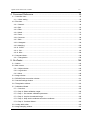
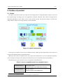
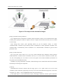
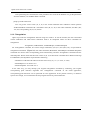
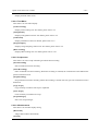
The goal of RIL is to provide the environment which an application engineer can make a hand-eye system
easily with low-cost. To achieve this goal, RIL consists of only software, and it can use many cameras on the
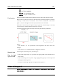
market. The architecture of RIL is shown below.
Figure 1-1 Architecture of RIL
1
OpenCV is a vision library developed by Intel, and it's opened under the License Agreement (Appendix D).
ORiN Forum
DENSO WAVE Inc.
OpenCV Provider User’s Guide
-9-
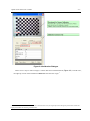
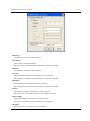
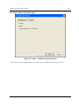
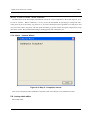
1.1. Installing license
To use OpenCV Provider, you need to install ORiN2 SDK, and also need to input “DENSO Robot Imaging
Libary” license information. If you would like to install it for evaluation, please use the following license.
CVG3-MZPB-7W2G-L43Q (valid for 3 months)
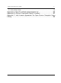
How to add the license is as follows.
1.
Run the CaoConfig tool from the [Start] menu, and select the [Cao Provider] tab.
2.
Select the [OpenCV CAO Provider] item on the provider list.
3.
Click the [...] button of the license input box.
4.
Click the [Add] button in the "ORiN2 License Manager" window.
5.
Input a license key, and click the [OK] button.
6.
Click the [Close] button to exit.
Figure 1-2 Installing 'DENSO Robot Imaging Library' license
ORiN Forum
DENSO WAVE Inc.
OpenCV Provider User’s Guide
- 10 -
2. Outline of provider
2.1. Outline
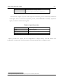
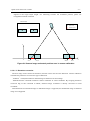
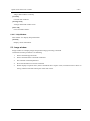
The OpenCV provider acquires the image from the imaging device using DirectShow. OpenCV processes
the acquired image according to the user application command. Therefore many kinds of imaging device
supporting DirectShow on the market can be used with this provider. The processed image is stored in the
image memory. Details of the image memory are described later.
Figure 2-1 System Configuration
Certain types of cameras can be used as extended cameras. ORiN2 provider dedicated for each camera can
configure the detailed setting of extended cameras.
ORiN2 provider used by extended camera may require the manufacturer’s driver. For detailed information,
refer to manuals of each provider. When you install the driver, do not install the driver of DirectShow.. 2
The following two types of cameras can be recognized as extended camera..
Table 2-1 List of compatible models for extended camera
Extended camera 1
Basler GigE camera
ORiN2¥CAO¥ProviderLib¥Basler¥Pylon¥GigE
Extended camera 2
IDS uEye camera
ORiN2¥CAO¥ProviderLib¥IDS¥uEye
2
If DirectShow driver is installed, the camera will not be recognized as an extended camera
ORiN Forum
DENSO WAVE Inc.
OpenCV Provider User’s Guide
- 11 -
Extended camera 3
Canon webView Livescope camera
ORiN2¥CAO¥ProviderLib¥Canon¥WebView
The file format of OpenCV provider is DLL (Dynamic Link Library); that is automatically loaded from
CAO engine when it is used. To use OpenCV provider, install ORiN2SDK or manually register the
registry in reference with the following table.
Table 2-1 OpenCV provider
File name
CaoProvOpenCV.dll
ProgID
Registry registration
CaoProv.OpenCV
3
Registry unregistration
Regsvr32 CaoProvOpenCV.dll
Regsvr32 /u CaoProvOpenCV.dll
OpenCV provider uses registry to store configurations of image memory area and cameras. The
configuration is changed with CaoConfig software. The following table shows configuration items.
3
Manual registration/unregistration is not necessary if the provider is installed by ORiN SDK.
ORiN Forum
DENSO WAVE Inc.
OpenCV Provider User’s Guide
- 12 -
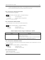
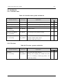
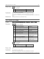
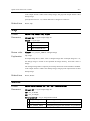
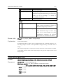
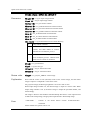
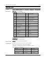
Table 2-2 CaoConfig Parameter strings
Parameter
Meaning
Database=<Database file name>
Specify an absolute file path of ACCESS database. If
omitted, the system uses the default database. That is
'opencv_en.mdb' stored in the bin directory. Please use
the following file as a template.
<OpenCV>¥Bin¥opencv_master_en.mdb
DefaultCamera=<default camera ID>
Specify default camera ID (default: 1).
If ID option is omitted for AddFile, Default Camera ID is
used for file object creation.
ImgMax=< image memory size >
Specify the entire image memory size. (default: 200)
ImgDBMax=< database area size >
Specify the image memory database area size. (default:
100)
If the specified value is larger than ImgMax, all image
memory is assumed to be stored in database.
CameraDisable
[=<disabled camera>]
Specify the disabled cameras. Bit0 corresponds to camera
ID=0, and Bit0 to Bit9 is specified. (default: 0x00)
big ON: camera disabled
bit OFF: camera enabled
FormatType
Specify the display size of each camera.
=<camera0 display size>:
[<camera1 display size>:
・・・
[<camera9 display size>: ]]
(default: 0: 0: 0: 0: 0: 0: 0: 0: 0)
-1:default
The value range depends on the camera. (0~)
If an invalid value was specified, the default value is used
instead.
FrameRate
Specify the frame rate of each camera.
=<camera0 frame rate>:
[<camera1 frame rate>:
・・・
(default: 0: 0: 0: 0: 0: 0: 0: 0: 0)
If an invalid value was specified, the default value is used
instead.
[<camera9 display size>: ]]
ExtCamera
[=<Basler GigE camera count >:
Specify the number of extended camera.
(default: 0:0)
[<IDS uEye camera count>]]
ORiN Forum
DENSO WAVE Inc.
OpenCV Provider User’s Guide
- 13 -
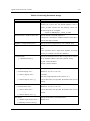
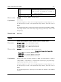
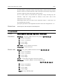
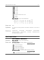
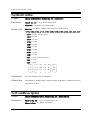
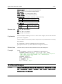
2.1.1. Image memory
OpenCV provider can store the image data in the two types of data area, database area and memory area.
The data stored in the database area remains even if OpenCV provider unloaded (non-volatile), but the access
speed is very slow. Therefore please don’t use database area for a temporally use. On the other hand, the access
speed of the memory area is fast, but the data stored in the area is cleared at the end (Volatile).
Raw image area (Direct Show)
Database area (Slow)
Ex.
ImgMax=100
ImgDbMax=200
ExtCamera= 5: 5
ID = 1
2
10
Memory area (Fast)
Raw image area (Ext Camera)
11
…
Fixed Area
12
97
98 100 101 102 103
…
…
…
205 206
196 197 198 199 200 201
ImgDBMax
ImgMax
Basler
GigE cam
210
…
iDS
uEye cam
Figure 2-2 Image storage area
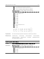
2.1.2. Calibration
The calibration commands of OpenCV provider can be divided into two categories, camera calibration and
robot-camera calibration. Those commands are as follows:
・ Camera calibration:
CalibrateCamera, GetCamCalData, SetCamCalData, GetCamCalExtData, SetCamCalExtData,
GetPosFromCam, GetCamPos, Undistort2
・ Robot-calibration:
CalibrateRobot, GetRobCalData, SetRobCalData, GetPosFromRob, GetRobPos
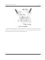
The relation among three coordinates, the world coordinate, camera coordinates and robot coordinates, are
shown below: where
・ The origin of the world coordinate is "Origin".
・ The origin of a robot coordinate is "Base".
ORiN Forum
DENSO WAVE Inc.
OpenCV Provider User’s Guide
- 14 -
Figure 2-3 Robot -Camera Calibration
The triangulation commands of CaoCommand class need to be done the camera calibration. The procedure
is as follows.
2.1.2.1. Camera calibration
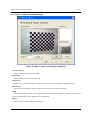
OpenCV Provider provides a simple calibration method using a chessboard to calibrate the intrinsic
parameters and the extrinsic parameters of the camera. The procedure is as follows.
[Step 1] Prepare chessboard image
Each camera requires at least five chessboard images. Store these images into appropriate consecutive
image area, e.g. 101-105. The first image is used as a reference image to calculate external parameter.
Input the reference image ID into ‘Input ID’ parameter of ‘CalibrateCamera’ command. The plane on
which the chessboard is placed when picturing the reference image is called as reference plane(Figure
2-4). The following directory of ORiN2 SDK stores the chessboard image that can be used for
calibration.
<ORiN2>/CAO/ProviderLib/OpenCV/Doc/Chessboard.pdf
ORiN Forum
DENSO WAVE Inc.
OpenCV Provider User’s Guide
- 15 -
Figure 2-4 Calibration Dialogue
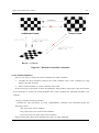
There are two ways to take 5 images, a camera shift and a chessboard shift (Figure 2-5). In both cases,
the right-top corner of the left-bottom "black box" becomes the origin. 4
4
In case of a chessboard which there is no black box in the left-bottom corner, the origin may become the right-top corner. Please confirm the
origin by GetCamPos after executing CalibrateCamera.
ORiN Forum
DENSO WAVE Inc.
OpenCV Provider User’s Guide
- 16 -
Figure 2-5 Two ways to take chessboard images
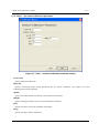
[Step 2] Calculate camera parameters
Use 'CalibrateCamera' command to calculate camera parameters. When you use chessboard file image
in SDK, please specify the values for ‘Square count W’, ‘Square count H’ and ‘Grid size (mm)’ as written
on each image.
After setting these values, press [Execute] button (if you use OpenCV tester), or invoke
‘CalibrateCamera’ command (if you directly call the command) for camera parameter calculation. The
calculated data is automatically stored in database. Use ‘GetCamCalDat’ command to get the stored
parameter value.
[Step 3] Confirm the result
You can get the correct value (X, Y, Z) in the world coordinate after calibration. Please perform
'GetPosFromCam' command with a reasonable value (Xc, Yc) in the camera coordinate, and then (Xw,
Yw, Zw) corresponding (Xc, Yc) returns. In case of two points on the world coordinate, the distance of
two points can be calculated correctly.
In addition, by using 'Undistort2' command, a distorted image can be undistorted. Please check whether
the linearity of the image was improved.
[Caution]
GetPosFromCam function assumes that the target point is on a plane where Z=0 in the world
coordinate system. Therefore, positioning error may occur if the camera detected target point is not on the
Z=0 plane (e.g. X1obj – X1cal in Figure 2-6 shows the positioning error.)
If the target object is a three-dimensional object with height, calibration reference plance should be
ORiN Forum
DENSO WAVE Inc.
OpenCV Provider User’s Guide
- 17 -
aligned to the target object height. For measuring accurate 3D coordinate position, please use
triangulation method command.
Camera Image
Object center
GetPosFromCam
Z
O
X
X1CAL
X1object
X2Object
X2CAL
Figure 2-6 Camera image and actual position error in camera calibration
2.1.2.1.1. Distortion correction
The shot image of the camera has distortion, because camera lens also has distortion. Camera calibration
calculates the parameters to correct this type of distortion.
‘Undistort’ command transforms distoted image to distortion-corrected image.
‘GetPosFromCam’command transforms camera coordinate to world coordinate. By assigning distortion
correction flag of this command as TRUE, distorted image coordinate is directly converted to world
coordinate.
Transformation from distorted image to undistorted image is supported, but undistorted image to distorted
image is not supported.
ORiN Forum
DENSO WAVE Inc.
OpenCV Provider User’s Guide
- 18 -
Figure 2-7 Distortion correction commands
2.1.2.2. Robot calibration
There are two ways to connect the world coordinate and a robot coordinate:
1.
Calculate the robot parameters between the world coordinate and a robot coordinate by using
OpenCV provider functions.
2.
Set the world coordinate as a work coordinate of the robot.
In this section, the 1st procedure is shown. Regarding the 2nd procedure, please refer to the robot manual.
If you don't have to connect the world coordinate and a robot coordinate, the following procedure is not
required.
[Step 1] Calculate the robot parameters
Calculate the robot parameters by using 'CalibrateRobot' command. This command requires the
following 3 points:
・ The origin of the world coordinate.
・ One point on the X axis of the world coordinate.
・ One point on the X-Y plane of the world coordinate.
Please note that those three points should be the points of a robot coordinate.
ORiN Forum
DENSO WAVE Inc.
OpenCV Provider User’s Guide
- 19 -
After performing the command, the robot parameters are stored in the database. To get the parameters
from the database, use 'GetRobCalDat' command.
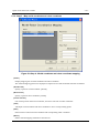
[Step 2] Confirm the result
You can get the correct value (X, Y, Z) in the world coordinate after calibration. Please perform
'GetPosFromRob' command with a reasonable value (Xr, Yr, Zr) in the robot coordinate, and then (Xw,
Yw, Zw) corresponding (Xr, Yr, Zr) returns.
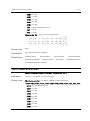
2.1.3. Triangulation
OpenCV provider has triangulation function using two cameras. To use the function, the above described
camera calibration and robot-camera calibration need to be completed. There are three commands for
triangulation.
Triangulation, TriHaarDetect, TriMatchShapes, TriMatchTemplate
For 'Triangulation' command, two camera image coordinates, (X1c,Y1c) and (X2c,Y2c), are specified for
triangulation calculation. (Figure 2-8). For other commands, HaarDetect, MatchShapes2 and MatchTemplate2
commands are used to detect corresponding points automatically, and then ‘Triangulation’ command uses the
detected points. Please notice that the return values of (X, Y) of these three commands have different meanings.
For HaarDetect, the adjustment is performed as following.
・ HaarDetect: Add half of W and H to the first result of (X, Y), i.e. (X + W/2, Y + H/2)
・ MatchShapes2: Use result as it is.
・ MatchTemplate2: Use result as it is.
In the same way, you may develop your original triangulation command by combining your original
corresponding point detection algorithm and ‘Triangulation’ command. In the actual application,
corresponding point detection can be optimized for each application. If the position accuracy or detection
speed is not enough, we recommend to develop original routine for position detection.
ORiN Forum
DENSO WAVE Inc.
OpenCV Provider User’s Guide
- 20 -
Figure 2-8 Triangulation
Triangulation command returns the coordinate position from the origin of the reference image. Camera
position is also represented using the same origin, and you can easily calculate the distance between the
camera and the target object using Distance command.(Figure 2-9).
ORiN Forum
DENSO WAVE Inc.
OpenCV Provider User’s Guide
- 21 -
Figure 2-9 Distance calculation
2.1.4. Message transfer function
By using message transfer function of CAO engine, image data stored in received message can be
transferred to the specified image ID.
Transfer destination is specified by MsgDestID option of AddController(). To transfer images from plural
sources to different image ID destinations, create plural CaoController objects and specify different destination
image ID in AddController().
When transfer message data is not bitmap file, the data is not stored.
ORiN Forum
DENSO WAVE Inc.
OpenCV Provider User’s Guide
- 22 -
2.2. Method and Property
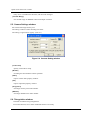
2.2.1. CaoWorkspace::AddController method
The OpenCV provider searches camera and performs connection process at AddController.
If you don't use the option character, it uses setting which registered in registry. (refer 2.1)
Format.
AddController( <bstrCtrlName: BSTR>,<bstrProvName: BSTR>,
<bstrPcName: BSTR > [,<bstrOption: BSTR>] )
bstrCtrlName
: [in] controller-name
bstrProvName
: [in] provider name. "CaoProv.OpenCV fixed value ="
bstrPcName
: [in] provider process execution machine name
bstrOption
: [in] option character string
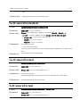
Table 2-3 option character string table
Option
Meaning
QREnabled=True/False
"QRDecode" Command Enable. Default=False
OCREnabled =True/False
" OCRead " Command Enable. Default=False
MsgDestID=<image ID>
Specify destination image ID for message
transfer.
FormatType=t1:t2:t3:t4:t5:t:t7:
Specify the display size of each camera.
t8:t9:t10
If an invalid value was specified, the default
value is used instead.
Ex. Use No2 camera format to camera2.
FormatType=0:2:0:0:0:0:0:0:0:0
FrameRate=f1:f2:f3:f4:f5:f6:f7
Specify the frame rate of each camera.
:f8:f9:f10
If an invalid value was specified, the default
value is used instead.
Ex. Use 30 frame rate to camera2.
FormatType=0:30:0:0:0:0:0:0:0:0
When AddController failed, it might be caused by the following problems.
・ Camera device failure
A camera device might not be working properly. Please check the camera with "amcap.exe" program
included in the DirectX samples.
・ Image database failure
A database file might be broken. Please delete “opencv.mdb” file located in the
ORiN Forum
DENSO WAVE Inc.
OpenCV Provider User’s Guide
- 23 -
“CAO/ProviderLib/OpenCV/Bin” directory. A new database file will be generated automatically at
the next startup. But all image data stored in the deleted file are discarded.
2.2.2. CaoController::AddCommand method
Create CaoCommand for triangulation.
Format AddCommand( <bstrName: BSTR > [,<bstrOption: BSTR>] )
bstrName
: [in] command name
bstrOption
: [in] option character string(unused)
Refer4.3.1for available commands.
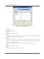
2.2.3. CaoController::AddFile method
Create a file object to access camera device and the image memory.
Format AddFile( <bstrName: BSTR > [,<bstrOption: BSTR>] )
bstrName
: [in] arbitrary name
bstrOption:
: [in] option character string
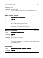
Table 2-4 Option character string of CaoWorkspace::AddFile
Option
Meaning
ID[=<image number>]
Initially connected image memory number
(default: default camera ID)
When this option is omitted, file object is connected to the default
camera ID specified in “DefaultCamera of Table 2-2 .
2.2.4. CaoController::AddVariable method
Creates variable object of camera device and image memory information. Only variable names on 2.3.1can
be used for this method.
Format AddVariable( <bstrName: BSTR > [,<bstrOption: BSTR>] )
bstrName
: [in] Arbitrary name
bstrOption
: [in] Option character string
2.2.5. CaoController::Execute
Execute specified command.
Refer to 4.1 for details of each commands.
ORiN Forum
DENSO WAVE Inc.
OpenCV Provider User’s Guide
- 24 -
2.2.6. CaoController::get_VariableNames property
The variable list is acquired. Please refer to 2.3.1 for the acquired variable.
2.2.7. CaoCommand::Execute method
Execute specified command.
Refer to 4.3 for details of each commands.
2.2.8. CaoCommand::put_Parameter property
Set parameters for a command.
Refer to 4.3 for details of each commands. This property does not check illegal parameters.
2.2.9. CaoCommand::get_Parameter property
Get parameters set by 2.2.8 . When the parameter is not set, VT_EMPTY is Return valued.
2.2.10. CaoCommand::get_Result property
Get latest execution result of 2.2.7. Refer to 4.3.1 for result of each commands.
2.2.11. CaoFile::Execute method
Execute image processing or the arithmetic processing specified by the command name.
The arguments of the Execute method are specified by BSTR for command and VARIANT array for
parameters.
Format [<vntRet: VARIANT> = ] Execute( <bstrCmd: BSTR > [,<vntParam: VARIANT>] )
bstrCmd
: [in] command
vntParam
: [in] parameter
vntRet
: [out] Return value
Refer to “4 Command Reference” for details of each command.
2.2.12. CaoFile::get_Attribute property
Get the kind of image memory.
2
Camera
3
Database area
4
Memory area
ORiN Forum
DENSO WAVE Inc.
OpenCV Provider User’s Guide
- 25 -
2.2.13. CaoFile::put_ID property
Change referred image memory.
2.2.14. CaoFile::get_ID property
Get ID of the currently referring image memory.
2.2.15. CaoFile::get_DateLastModified property
Get last modified date of the currently referring image memory.
VT_EMPTY will be returned if the memory does not have image.
2.2.16. CaoFile::Get_Size property
Get file size of the referring image memory.
2.2.17. CaoFile::put_Value property
Overwrite BMP format image to the currently referring image memory.
The image is overwritten as a color image.
2.2.18. CaoFile::get_Value property
Get BMP format image from the currently referring image memory.
Color image is acquired as 24bits bitmap image, and grayscale image is acquired as 8bits bitmap image.
2.2.19. CaoFile::get_Help property
Get character strings that have been set by the PutHelp command.
If camera area is specified, a camera name will be obtained.
2.2.20. CaoController::OnMessage event
Updating image data generates OnMessage event of CaoController class. With this event, Message::Number
property is set to 1, and Message::Value property is set to the image number.
ORiN Forum
DENSO WAVE Inc.
OpenCV Provider User’s Guide
- 26 -
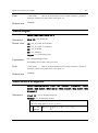
2.3. Variable list
2.3.1. Controller class
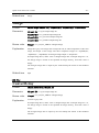
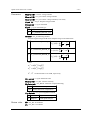
Table 2-5 Controller class system variable list
Attribute
Variable identifier
Data type
Explanation
get
put
@IMG_MAX
VT_I4
Size of the entire image memory
√
‐
@IMGDB_MAX
VT_I4
Size of data base area of image memory
√
‐
@CAM_COUNT
VT_I4
Number of connected cameras
√
‐
@VERSION
VT_BSTR
Provider version
√
‐
VT_BOOL
CAO message event generation setting
√
√
Number of extended camera.
√
-
[V1.3.5 or later]
@EVENT_ENABLED
[V1.3.5 or later]
@EXT_CAM_COUNT
VT_I4
|
[V1.4.6 or later]
VT_ARRAY
<Number of Basler GigE camera>
<Number of IDS uEye camera>
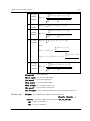
2.3.2. File class
Table 2-2 File class system variable list
Variable identifier
Data type
Attribute
Explanation
@VALUE
VT_UI1
|
[V1.3.5 or later]
VT_ARRAY
Image data in the image memory
get
put
√
√
Referring and assigning the variable has same
effect as executing CaoFile::get_Value() and
CaoFile::put_Value().
ORiN Forum
DENSO WAVE Inc.
OpenCV Provider User’s Guide
- 27 -
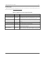
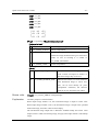
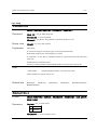
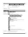
2.4. Error code
Open CV provider defines folloing specific error codes. For common error code for ORiN2, please refer to
the error code section of “ORiN2 Programming guide”.
Table 2-3 Specific error code for OpenCV provider
Error name
Error code
Explanation
E_CAOP_NO_LICENSE
0x80100000
There is no license. Please purchase an additional license.
E_CAOP_DB_RESTORE
0x80100001
The database file (mdb) was crashed. Because it was recoverd
automatically from the last mdb, restartd your program.
E_CAOP_INITTERM
0x80100002
The another process is initializing or terminating. Please wait a
minute.
E_CAOP_NOIMAGE
0x80100003
No image.
E_CAOP_LOCK_IMAGE
0x80100004
The another program is using the image.
Original error code.
0x801010xx
The original error code depending on a command.
Please refer to the chapter 4.
OpenCV API Error
0x8011xxxx
OpenCV API error number will be assigned at “xxxx” part of
the error code. Please refer OpenCV reference for the details.
ORiN Forum
DENSO WAVE Inc.
OpenCV Provider User’s Guide
- 28 -
3. Sample program
RIL programs can be developed with various programming languages (C/C++, VB, etc.) The easiest way is
to use RIL is to use CaoScript, a VB Script based scripting language. CaoScript is included in ORiN2 SDK.
Section 3.1explains CaoScript sample program. For other samples, refer to section 3.2
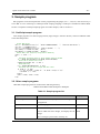
3.1. CaoScript sample program
This sample program is to detect target position (target image is stored in ID101), and move DENSO robot
to the detected position.
' Create CAO object
Set rc = Cao.AddController("rc", "CaoProv.DENSO.NetwoRC", "", "Conn=eth:192.168.0.1")
Set robo = rc.AddRobot("vp")
Set vis = Cao.AddController("cv", "CaoProv.OpenCV", "", "")
Set rawImg = vis.AddFile("cam1", "ID=1")
Set tmpImg = vis.AddFile("mem1", "ID=101")
' Search and trace target by using pattern matching
OldX = -1: OldY = -1
Do
' Calculate threshold level by discriminant analysis method
iT = rawImg.AutoThreshDiscrim(rawImg.CalcHistEx(255))
' Binarization & B/W inversion(1)
rawImg.ThresholdEx 101, iT, 255, 1
' Shape matching
res = tmpImg.MatchShapes2(11, 2, 0.2)
' Calculate position shift length and move robot
If (OldX <> -1) Then
v = "V(" & (OldX - res(0)) & "," & (OldY- res(1)) & ",0)"
robo.Draw 1, v, "next"
End If
OldX = res(0): OldY = res(1)
Loop
3.2. Other sample programs
Other RIL sample programs are located in the following directory.
<ORiN2>¥CAO¥ProviderLib¥ OpenCV ¥Samples
Table 3-1 Sample program list
Program
Contents
3DTracking
Robot
Language
motion
by
pattern
matching
and
Visual Basic 6
triangulation.
Benchmark
Short test programs for benchmark.
Excel VBA
CutImage
Cut camera 0 image from coordinate point (0,0) to
Visual
100 in width and 100 in height, and display the cut
2005
Basic
image.
The cut image is preserved in memory #11.
ORiN Forum
DENSO WAVE Inc.
OpenCV Provider User’s Guide
DENSO NetwoRC
- 29 Search for a specified target image in the camera
Visual Basic 6
image, and store the detected coordinate into a
variable
of
the
controller
with
IP address
“10.6.235.60”.
Filter
Display the image from camera in the following
four patterns.
Visual
Basic
2005
・ raw image
・ gray-scale image
・ binary image
Canny filtered image
FindCountoursEx
Execute FindCountoursEx command.
C
Histogram
Generate a histogram of camera 1 image.
Visual
Basic
2005
Others
Robot motion by pattern matching.
CaoScript
SaveImage
Save camera 1 image in image memory #11.
Visual
Basic
2005
ORiN Forum
DENSO WAVE Inc.
OpenCV Provider User’s Guide
- 30 -
4. Command Reference
This chapter shows the details of each OpenCV provider command. Regarding the detailed behavior of the
commands depending on OpenCV library deeply, please refer the OpenCV manual like the followings. And
regarding the used OpenCV functions in the OpenCV provider commands, please see 5.10.Appendix A.
[OpenCV Japanese manual]
http://opencv.jp/opencv-1.0.0/document/
[OpenCV English manual]
http://opencv.jp/opencv-1.0.0_org/docs/index.htm
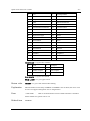
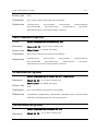
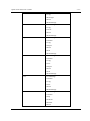
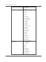
Table 4-1 Controller class command list
Category
Command name
Function
Video Setting
SetFormat 5
GetFormatList5
OpenFileterProperty
OpenPinProperty
SetCtrlMode
GetCtrlMode
GetRangeCameraCtrl
GetCameraCtrl
SetCameraCtrl
GetRangeVideoProcAmp
GetVideoProcAmp
SetVideoProcAmp
GetCameraFormatList
GetCameraFormat
SetCameraFormat
ExtExecSoftTrigger
ExtRefreshImage
ExtInvoke
ExtConnect
ExtDisconnect
ExtIsConnected
ExtGetConnectOption
ExtSetConnectOption
5
Set a video format
Get a video format list
Open a filter property window
Open an output Pin property window
Set a video control mode
Get a video control mode
Get a parameter range of a camera control
Get a parameter of a camera control
Set a parameter of a camera control
Get a parameter range of a video control
Get a parameter of a video control
Set a parameter of a video control
Get camera format list.
Get camera format ID.
Set camera format ID.
Execute software trigger
Refresh extended camera's image
Execute extended camera's command
Connect extended camera.
Dicconnect extended camera.
Connection check of extended camera
Get extended camera's connection option
Set extended camera's connection option
P.35
P.35
P.35
P.36
P.36
P.37
P.37
P.38
P.39
P.40
P.41
P.41
P.41
P.42
P.42
P.42
P.43
P.43
P.44
P.44
P.44
This command was integrated into the OpenPinProperty command.
ORiN Forum
DENSO WAVE Inc.
OpenCV Provider User’s Guide
- 31 -
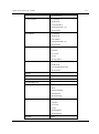
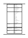
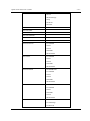
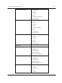
Table 4-2 File class command list
Category
Command name
Function
General
SetROI
GetROI
ResetROI
PutColor
GetColor
SearchPoint
Trim
ImageSize
IsColor
IsEmpty
IsUpdated
ClearUpdated
Distance
InnerProduct
OuterProduct
PutHelp
Set a ROI (Region Of Interest)
Get current ROI.
Reset current ROI setting.
Put color
Get color
Search point
Trimming
Get image size
Color image flag
Detemine whether an image data is empty
Detemine whether an image data is updated
Clear IsUpdated flag
Measure distance
Inner product of two vectors
Outer product of two vectors
Set character strings
P.46
P.46
P.47
P.47
P.48
P.48
P.49
P.50
P.50
P.51
P.51
P.51
P.51
P.52
P.52
P.53
Copy
Cut
Paste
Rotate
Flip
Resize
Split
Merge
Copy image
Cut image
Paste image
Rotate image
Flip image
Resize image
Split color space
Merge color space
P.53
P.54
P.54
P.55
P.56
P.56
P.57
P.58
ConvertGray
ThresholdEx
Threshold2
AdaptiveThresholdEx
Smooth
Sobel
Laplace
CannyEx
WarpAffine
WarpPerspective
PreCornerDetectEx
CornerHarrisEx
CalcBackProjectEx
Inpaint
Erode
Dilate
Convert to gray scale
Threshold process
Applies fixed-level threshold
Adaptive threshold process
Smoothing
Sobel filter
Laplace filter
Canny filter
Affine transformation
Perspective transformation
Corner detector
Harris edge detector
Calculate back projection
Inpainting
Erode image
Dilate image
P.58
P.59
P.60
P.61
P.62
P.63
P.64
P.65
P.65
P.66
P.68
P.68
P.69
P.69
P.70
P.71
Edit
Filter
ORiN Forum
DENSO WAVE Inc.
OpenCV Provider User’s Guide
- 32 -
PyrDown
PyrUp
Down sampling
Upsanmpling
P.71
P.72
NOT
AND
OR
XOR
ADD
SUB
MAXEx
MINEx
ABS
LUT
SetLUT
GetLUT
Bit inversion
Logical AND
Logical OR
Logical Exclusive OR
Addition
Subtraction
Maximum value
Minimum value
Absolute value
Lookup table translation
Set lookup table
Get lookup table
P.73
P.73
P.74
P.74
P.75
P.75
P.76
P.76
P.77
P.77
P.78
P.78
Line
Line2
Rectangle
Circle
Ellipse
Sector
Cross
Text
Draw a line (between two specified points)
Draw a line (length specified)
Draw a square
Draw a circle
Draw an ellipse
Fill eclipse sector
Cross drawing
Display character string
P.79
P.79
P.80
P.81
P.82
P.83
P.84
P.85
FindContoursEx
CopyContours
ContoursNumber
PointPolygonTest
BoundingRect
FitEllipse
ArcLength
CheckContourConvexity
DrawContours
Detect contour.
Copy contour image
Retrieve contour ID
Check the position relation of a point and a contour
Find a rectangle bounding a contour
Get minimum ellipse bounding the specified contour
Get contour boundary length
Check shape convexity
Draw contours
P.86
P.87
P.88
P.88
P.89
P.89
P.90
P.90
P.90
FindBlobs
BlobsFilter
BlobResult
BlobResults
BlobEllipse
BlobMatchTemplate
BlobMatchShapes
Find blobs
Filter the result of FindBlobs
Get the blob information by ID
Get all blob information
Get an ellipse fitting the blob
Detection blob template matching
Detection blob shape matching
P.92
P.92
P.95
P.95
P.96
P.96
P.98
CalcHistEx
NormalizeHistEx
ThreshHistEx
EqualizeHistEx
GetMinMaxistValue
Calculate histogram
Normalize histogram
Threshold histogram
Equalize histogram
Get maximum and minimum value of histogram
P.99
P.99
P.100
P.100
P.100
Mask
Draw
Contours
Blob
Histogram
ORiN Forum
DENSO WAVE Inc.
OpenCV Provider User’s Guide
- 33 -
HistAve
AutoThreshPTile
AutoThreshMode
AutoThreshDiscrim
Calculate average luminance.
Calculate threshold value using P-tile method
Calculate threshold value using mode method
Calculate threshold value using discrimination
analysis method
P.101
P.101
P.101
P.102
MatchTemplate
MatchShapesEx
MatchTemplate2
MatchShapes2
CamShift
HaarDetect
Template matching
Contour matching
Extended template matching
Extended shape matching
Object tracking
Haar matching
P.102
P.104
P.104
P.106
P.108
P.109
CARDInit2
CARDRun2
Register the template image for CARD
Excute CARD command
P.109
P.110
CalibrateCamera
CalibrateRobot
FindChessBoardCorners
DrawChessBoardCorners
DrawXYAxes
SetCamCalDat
GetCamCalDat
SetCamCalExtDat
GetCamCalExtDat
ModifyCamCalExtDat
SetRobCalDat
GetRobCalDat
SetCameraDescription
GetCameraDescription
SetRobotDescription
GetRobotDescription
GetPostFromCam
Calibrate camera
Calibrate robot
Find corner of the chessboard
Draw the corners of the chessboard
Draw XY axis
Set calibration data
Get calibration data
Set external variables of camera calibration
Get external variables of camera calibration
Modify camera calibration external data
Set robot calibration data
Get robot calibration data
Set camera calibration description
Get camera calibration description
Set robot calibration description
Get robot calibration description
Convert from camera image coordinate to world
coordinate
Convert from world coordinate to camera image
coordinate
Convert from robot coordinate to world coordinate
Convert from world coordinate to robot coordinate
Conver from camera image coordinate to robot
coordinate
Conver from robot coordinate to camera image
coordinate
Image distortion compensation
P.112
P.113
P.114
P.115
P.115
P.116
P.117
P.118
P.119
P.120
P.121
P.122
P.122
P.123
P.123
P.123
P.124
Determines corners on image
Refine corner detection result
Calculate moment
Calculate area size, gravity center, and principal axis
angle
P.128
P.129
P.130
P.131
Matching
CARD
CAL
GetCamPos
GetPostFromRob
GetRobPos
GetRobPosFromCam
GetCamPosFromRob
Undistort2
P.125
P.125
P.126
P.126
P.127
P.128
Misc.
GoodFeatureToTrackEx
FindCornerSubPixEx
MomentsEx
MeasureInfo
ORiN Forum
DENSO WAVE Inc.
OpenCV Provider User’s Guide
HoughLine
HoughCircles
DFTEx
IDFT
OpticalFlowEx
OpticalFlowPyrEx
BoxPoints
FindHomography
QRDecode
OCRead
- 34 Find lines using Hough transform
Find circles using Hough transform
Fourier transform
Inverse Fourier transform
Calculate optical flow for two images
Optical flow using image pyramid
Calculate the four corner positions of the specified
rectangular.
Calculate projection matrix
Decode several types of two dimensional code such
as QRCode
Character recognition
P.131
P.132
P.133
P.133
P.134
P.134
P.135
P.136
P.137
P.137
Table 4-3 Command class command list
Category
Command name
Function
Triangulation
Triangulation
TriMatchTemplate
TriMatchShapes
TriHaarDetect
ORiN Forum
Triangulation
Template matching + Triangulation
Shape matching + Triangulation
Haar matching + Triangulation
P.138
P.138
P.140
P.142
DENSO WAVE Inc.
OpenCV Provider User’s Guide
- 35 -
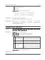
4.1. Controller class
4.1.1. Video setting
OpenFilterProperty
Format
object.OpenFilterProperty <Camera ID>, <Window Handle>
Parameters
<Camera ID> = VT_I4: Camera ID6
<Window Handle> = VT_I4: Handle to parent or owner window
Return value
None
Explanation
Open a camera filter property window.
OpenPinProperty
Format
object.OpenPinProperty(<Camera ID>, <Window Handle>)
Parameters
<Camera ID> = VT_I4: Camera ID
<Window Handle> = VT_I4: Handle to parent or owner window
Return value
<Format ID> = VT_I4: Camera format ID
Explanation
Open an output Pin property window.
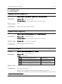
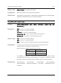
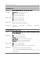
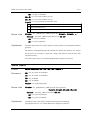
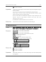
SetCtrlMode
Format
object.SetCtrlMode(<Camera ID>, <Mode>)
Parameters
<Camera ID> = VT_I4: Camera ID
<Mode> = VT_I4: Mode
1
VideoControlFlag_FlipHorizontal
Horizontal flip
2
VideoControlFlag_FlipVertical
Vertical flip
4
VideoControlFlag_ExternalTriggerEnable
External trigger enable
8
VideoControlFlag_Trigger
External trigger simulation
Return value
None
Explanation
Set a video control mode.
Please refer to IAMVideoControl::SetMode() with MSDN for the details.
[Caution] This command may not be executed properly depending on a camera driver
6
The number 1 to 10 are called 'Camera ID' for convenience.
ORiN Forum
DENSO WAVE Inc.
OpenCV Provider User’s Guide
- 36 -
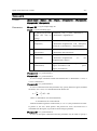
used.
Related item
GetCtrlMode
GetCtrlMode
Format
object.GetCtrlMode(<CameraID>)
Parameters
<CameraID> = VT_I4: Camera ID
Return value
<Mode> = VT_I4: Mode
1
VideoControlFlag_FlipHorizontal
Horizontal flip
2
VideoControlFlag_FlipVertical
Vertical flip
4
VideoControlFlag_ExternalTriggerEnable
External trigger enable
8
VideoControlFlag_Trigger
External trigger simulation
Explanation
Get a video control mode.
Related item
Please refer to IAMVideoControl::SetMode() with MSDN for the details.
[Caution] This command may not be executed properly depending on a camera driver
used.
SetCtrlMode
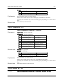
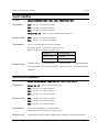
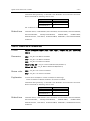
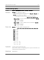
GetRangeCameraCtrl
Format
object.GetRangeCameraCtrl(<CameraID>, <Property>)
Parameters
<CameraID> = VT_I4: Camera ID
<Property> = VT_I4: Property ID
Return value
0
CameraControl_Pan
Pan (degree)
1
CameraControl_Tilt
Tile (degree)
2
CameraControl_Roll
Roll (degree)
3
CameraControl_Zoom
Zoom (mm)
4
CameraControl_Exposure
Exposure (2n Sec.)
5
CameraControl_Iris
Iris (fstop * 10)
6
CameraControl_Focus
Focus (mm)
<Min> = VT_I4: Min value
<Max> = VT_I4: Max value
<Step> = VT_I4: Step
<Default> = VT_I4: Default value
ORiN Forum
DENSO WAVE Inc.
OpenCV Provider User’s Guide
- 37 -
<Flag> = VT_I4: Flag
1
CameraControl_Flags_Auto
Automatic Control
2
CameraControl_Flags_Manual
Manual Control
Explanation
Get a parameter range of a camera control.
Related item
Please refer to IAMCameraControl::GetRange() with MSDN for the details.
[Caution] This command may not be executed properly depending on a camera driver
used.
GetCameraCtrl, SetCameraCtrl
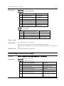
GetCameraCtrl
Format
object.GetCameraCtrl(<CameraID>, <Property>)
Parameters
<CameraID> = VT_I4: Camear ID
<Property> = VT_I4: Property ID
Return value
0
CameraControl_Pan
Pan (degree)
1
CameraControl_Tilt
Tile (degree)
2
CameraControl_Roll
Roll (degree)
3
CameraControl_Zoom
Zoom (mm)
4
CameraControl_Exposure
Exposure (2n Sec.)
5
CameraControl_Iris
Iris (fstop * 10)
6
CameraControl_Focus
Focus (mm)
<Value> = VT_I4: Value
<Flag> = VT_I4: Flag
1
CameraControl_Flags_Auto
Automatic control
2
CameraControl_Flags_Manual
Manual control
Explanation
Get a parameter of a camera control.
Related item
Please refer to IAMCameraControl::Get() with MSDN for the details.
[Caution] This command may not be executed properly depending on a camera driver
used.
GetRangeCameraCtrl, SetCameraCtrl
SetCameraCtrl
Format
ORiN Forum
object.SetCameraCtrl(<CameraID>, <Property>, <Value>, <Flag>)
DENSO WAVE Inc.
OpenCV Provider User’s Guide
Parameters
- 38 -
<CameraID> = VT_I4: Camera ID
<Property> = VT_I4: Property ID
0
CameraControl_Pan
Pan (degree)
1
CameraControl_Tilt
Tile (degree)
2
CameraControl_Roll
Roll (degree)
3
CameraControl_Zoom
Zoom (mm)
4
CameraControl_Exposure
Exposure (2n Sec.)
5
CameraControl_Iris
Iris (fstop * 10)
6
CameraControl_Focus
Focus (mm)
<Value> = VT_I4: Value
<Flag> = VT_I4: Flag
0x001
CameraControl_Flags_Auto
Automatic control
0x002
CameraControl_Flags_Manual
Manual control
0x000
CameraControl_Flags_Absolute
Absolute values
0x010
CameraControl_Flags_Relative
Relative values
Return value
None
Explanation
Set a parameter of a cemara control.
Related item
Please refer to IAMCameraControl::Set() with MSDN for the details.
[Caution] This command may not be executed properly depending on a camera driver
used.
GetRangeCameraCtrl, GetCameraCtrl
GetRangeVideoProcAmp
Format
object.GetRangeVideoProcAmp(<CameraID>, <Property>)
Parameters
<CameraID> = VT_I4: Camera ID
<Property> = VT_I4: Property ID
0
VideoProcAmp_Brightness
Brightness
1
VideoProcAmp_Contrast
Contrast (gain * 100)
2
VideoProcAmp_Hue
Hue (degree * 100)
3
VideoProcAmp_Saturation
Saturation
4
VideoProcAmp_Sharpness
Sharpness
5
VideoProcAmp_Gamma
Gamma (gamma * 100)
6
VideoProcAmp_ColorEnable
Color enabled
(0: OFF, 1: ON)
ORiN Forum
DENSO WAVE Inc.
OpenCV Provider User’s Guide
- 39 -
7
VideoProcAmp_WhiteBalance
White balance
8
VideoProcAmp_BacklightCompensation
Backlight compensation
(0: OFF, 1: ON)
9
Return value
VideoProcAmp_Gain
Gain
<Min> = VT_I4: Min value
<Max> = VT_I4: Max value
<Step> = VT_I4: Step
<Default> = VT_I4: Default value
<Flag> = VT_I4: Flag
1
CameraControl_Flags_Auto
Automatic control
2
CameraControl_Flags_Manual
Manual control
Explanation
Get a parameter range of a video control.
Related item
Please refer to IAMVideoProcAmp::GetRange() with MSDN for the details.
[Caution] This command may not be executed properly depending on a camera driver
used.
GetVideoProcAmp, SetVideoProcAmp
GetVideoProcAmp
Format
object.GetVideoProcAmp(<CameraID>, <Property>)
Parameters
<CameraID> = VT_I4: Camera ID
<Property> = VT_I4: Property ID
0
VideoProcAmp_Brightness
Brightness
1
VideoProcAmp_Contrast
Contrast (gain * 100)
2
VideoProcAmp_Hue
Hue (degree * 100)
3
VideoProcAmp_Saturation
Saturation
4
VideoProcAmp_Sharpness
Sharpness
5
VideoProcAmp_Gamma
Gamma (gamma * 100)
6
VideoProcAmp_ColorEnable
Color enabled
(0: OFF, 1: ON)
7
VideoProcAmp_WhiteBalance
White balance
8
VideoProcAmp_BacklightCompensation
Backlight compensation
(0: OFF, 1: ON)
9
ORiN Forum
VideoProcAmp_Gain
Gain
DENSO WAVE Inc.
OpenCV Provider User’s Guide
Return value
- 40 -
<Value> = VT_I4: Value
<Flag> = VT_I4: Flag
1
CameraControl_Flags_Auto
Automatic control
2
CameraControl_Flags_Manual
Manual control
Explanation
Get a parameter of a video control.
Related item
Please refer to IAMVideoProcAmp::Set() with MSDN for the details.
[Caution] This command may not be executed properly depending on a camera driver
used.
GetRangeVideoProcAmp, SetVideoProcAmp
SetVideoProcAmp
Format
object.SetVideoProcAmp(<CameraID>, <Property>, <Value>, <Flag>)
Parameters
<CameraID> = VT_I4: Camera ID
<Property> = VT_I4: Property ID
0
VideoProcAmp_Brightness
Brightness
1
VideoProcAmp_Contrast
Contrast (gain * 100)
2
VideoProcAmp_Hue
Hue (degree * 100)
3
VideoProcAmp_Saturation
Saturation
4
VideoProcAmp_Sharpness
Sharpness
5
VideoProcAmp_Gamma
Gamma (gamma * 100)
6
VideoProcAmp_ColorEnable
Color enabled
(0: OFF, 1: ON)
7
VideoProcAmp_WhiteBalance
White balance
8
VideoProcAmp_BacklightCompensation
Backlight compensation
(0: OFF, 1: ON)
9
VideoProcAmp_Gain
Gain
<Value> = VT_I4: Value
<Flag> = VT_I4: Flag
1
CameraControl_Flags_Auto
Automatic control
2
CameraControl_Flags_Manual
Manual control
Return value
None
Explanation
Set a parameter of a video control.
Please refer to IAMVideoProcAmp::Get() with MSDN for the details.
[Caution] This command may not be executed properly depending on a camera driver
ORiN Forum
DENSO WAVE Inc.
OpenCV Provider User’s Guide
- 41 -
used.
Related item
GetRangeVideoProcAmp, GetVideoProcAmp
GetCameraFormatList
Format
object.GetCameraFormatList(<CameraID>)
Parameters
Return value
<CameraID> = VT_I4: Camera ID
<Lists> = VT_VARIANT|VT_ARRAY:FormatList (<List1>, <List2>, …)
<Listn> = VT_I4|VT_ARRAY:Format (<Format ID>,<Width>,<Height>)
<Format ID> = VT_I4:Camera format ID (0~)
<Width> = VT_I4:X resolution
<Hegiht> = VT_I4:Y resolution
Explanation
Get camera format list.
-1 : Can’t use this Format ID.
[Caution] This command may not be executed properly depending on a camera driver
used.
Related item
GetCameraFormat, SetCameraFormat
GetCameraFormat
Format
object.GetCameraFormat(<CameraID>)
Parameters
<CameraID> = VT_I4:Camera ID
Return value
<Format ID> = VT_I4:Camera format ID (0~)
Explanation
Get camera format ID.
[Caution] Whether this command correctly works is depending on a camera driver.
Related item
GetCameraFormatList, SetCameraFormat
SetCameraFormat
Format
object.SetCameraFormat(<CameraID>, <Format ID>)
Parameters
<CameraID> = VT_I4:Camera ID
<Format ID> = VT_I4:Camera format ID (0~)
ORiN Forum
DENSO WAVE Inc.
OpenCV Provider User’s Guide
- 42 -
Return value
None
Explanation
Set camera format ID.
[Caution] Whether this command correctly works is depending on a camera driver.
Related item
GetCameraFormatList, GetCameraFormat
ExtExecSoftTrigger
Format
object.ExtExecSoftTrigger(<CameraID>)
Parameters
<CameraID> = VT_I4:Camera ID
Return value
None
Explanation
Execute software trigger of camera.
[V1.4.6or later]
This command is available only for extended camera.
This command runs “OCV_ExecSoftTrigger” command in CaoController::Execute() on
ORiN2 provider which is compatible with extended camera.
ExtRefreshImage
Format
object.ExtRefreshImage(<CameraID>)
Parameters
<CameraID> = VT_I4:Camera ID
Return value
None
Explanation
Update the image of extended camera
[V1.4.6or later]
This command is available only for extended camera.
This command runs OCV_GetImage command in CaoController::Execute() on ORiN2
provider which is compatible with the extended camera, and then update the internal
buffer with obtained image.
ExtInvoke
Format
object.ExtInvoke(<CameraID>, <Command>, <Parameter>)
Parameters
<CameraID> = VT_I4:Camera ID
ORiN Forum
[V1.4.6 or later]
DENSO WAVE Inc.
OpenCV Provider User’s Guide
- 43 -
<Command> = VT_BSTR:Command name
<Parameter> = VT_VARIANT:Parameter
Return value
<Result> = VT_VARIANT:Return value
Explanation
Execute the command of extended camera
This command is available only for extended camera.
This command runs CaoController::Execute() on ORiN2 provider which is compatible
with extended camera.
For the command name that can be specified by <Command>, or the contents of
<Parameter> or <Result>, refer to the user’s guide of ORiN2 provider corresponding with
the extended camera.
ExtConnect
[V1.5.1 or later]
Format
object.ExtConnect(<CameraID>)
Parameters
<CameraID> = VT_I4:Camera ID
Return value
<Connected> = VT_VARIANT:Result
Explanation
TRUE
Already connected
FALSE
New connection
Connect with the extended camera specified by <CameraID>
When an extended camera has not been connected, this command connects with an
extended camera. The return value is FALSE when it succeeds.
When the specified extended camera has been already connected, this command succeeds
without processing. The return value is TRUE.
Related item
ExtDisconnect, ExtIsConnected
ExtDisconnect
Format
object.ExtDisconnect(<CameraID>)
Parameters
<CameraID> = VT_I4:Camera ID
Return value
None
Explanation
Disconnect the extended camera specified by <CameraID>
ORiN Forum
[V1.5.1 or later]
DENSO WAVE Inc.
OpenCV Provider User’s Guide
Related item
- 44 -
This command always succeeds regardless of the connection state with an extended
camera.
ExtConnect, ExtIsConnected
ExtIsConnected
[V1.5.1 or later]
Format
object.ExtIsConnected(<CameraID>)
Parameters
<CameraID> = VT_I4:Camera ID
Return value
<Result> = VT_VARIANT:Result
Explanation
TRUE
Communication is possible.
FALSE
Communication is impossible.
Check the communication state with the extended camera specified by <CameraID>.
This command always succeeds regardless of the connection state with an extended
camera. When an extended camera has been connected and the communication is
available, this command returns TRUE. FALSE is returned in other status.
Related item
ExtConnect, ExtDisconnect
ExtGetConnectOption
Format
object. ExtGetConnectOption(<CameraID>)
Parameters
<CameraID> = VT_I4:Camera ID
Return value
<Parameter> = VT_BSTR:Connection Option
Explanation
Get extended camera's connection option.
Related item
ExtConnect, ExtDisconnect
ExtSetConnectOption
Format
object. ExtSetConnectOption(<CameraID>, <Parameter>)
Parameters
<CameraID> = VT_I4:Camera ID
[V1.5.2 or later]
[V1.5.2 or later]
<Parameter> = VT_BSTR:Connection Option
Return value
ORiN Forum
None
DENSO WAVE Inc.
OpenCV Provider User’s Guide
Explanation
Set extended camera's connection option.
Related item
ExtConnect, ExtDisconnect
ORiN Forum
- 45 -
DENSO WAVE Inc.
OpenCV Provider User’s Guide
- 46 -
4.2. File class
4.2.1. General
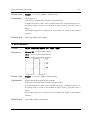
SetROI
Format
object.SetROI <ROI>
Parameters
<ROI>= VT_I4|VT_ARRAY:ROI Information (<X>, <Y>, <W>, <H>)
<X> = VT_I4: Start point X coordinates
<Y> = VT_I4: Start point Y coordinates
<W> = VT_I4: Width
<H> = VT_I4: Height
Return value
None
Explanation
Set region of interest(ROI).
After executing this command, the input and result about coordinates depend on <X>
and <y>.
Related item
GetROI, ResetROI
Example
[VB6]
vntParam = Array(0, 0, 200, 100)
caoFile.Execute “SetROI”, vntParam ‘ Set a ROI (0,0) – (200,100)
GetROI
Format
object.GetROI()
Parameters
None
Return value
<ROI>= VT_I4|VT_ARRAY:ROI Information(<X>, <Y>, <W>, <H>)
<X> = VT_I4: Start point X coordinates
<Y> = VT_I4: Start point Y coordinates
<W> = VT_I4: Width
<H> = VT_I4: Height
Explanation
Get value of ROI. VT_EMPTY returns when ROI is not set up.
Related item
SetROI, ResetROI
Example
[VB6]
vntRet = caoFile.Execute( “GetROI” ) ‘ Get current ROI
x = vntRet(0) ‘ <X>
y = vntRet(1) ‘ <Y>
ORiN Forum
DENSO WAVE Inc.
OpenCV Provider User’s Guide
- 47 -
w = vntRet(2) ‘ <W>
h = vntRet(3) ‘ <H>
ResetROI
Format
object.ResetROI()
Parameters
None
Return value
None
Explanation
Reset the parameter that set by SetROI command.
Related item
SetROI, GetROI
Example
[VB6]
caoFile.Execute “ResetROI”
PutColor
Format
object.PutColor <Output ID>,<X>, <Y>, <R>, <G>, <B>
Parameters
<Output ID> = VT_I4: Output Image ID
<X> = VT_I4: X coordinates
<Y> = VT_I4: Y coordinates
<R> = VT_I4: Red density
<G> = VT_I4: Green density
<B> = VT_I4: Blue density
Return value
<Image> = VT_UI1|VT_ARRAY: Changed Image
Explanation
Set color at the specified coordinate point.
For grayscale image, the point is changed to the value of <B>.
If Output Image ID=0, return value is changed image data. If Output Image Id <> 0,
the change image is stored in the specified ID image memory, and return value is
Empty.
The changed image data is output by the bitmap file format of the Windows standard.
Color output format is 24bit color bitmap image, and grayscale output format is 8bit
bitmap image.
Related item
ORiN Forum
GetColor, SearchPoint
DENSO WAVE Inc.
OpenCV Provider User’s Guide
Example
- 48 -
[VB6]
‘Draw a point in red at XY position (100,200) and output it to 101st image.
vntParam = Array(101, 100, 200, 255, 0, 0)
caoFile.Execute “PutColor”, vntParam
GetColor
Format
object.GetColor( <X>, <Y> )
Parameters
<X> = VT_I4: X coordinates
<Y> = VT_I4: Y coordinates
Return value
<Value>= VT_I4 or VT_I4|VT_ARRAY: Color density(<R>, <G>, <B>)
<R> = VT_I4: Red density
<G> = VT_I4: Green density
<B> = VT_I4: Blue density
Explanation
Get color at the specified coordinate point.
Color picture: Color density(VT_I4 | VT_ARRAY)
Grayscale picture: Brightness(VT_I4)
Related item
PutColor, SearchPoint
Example
[VB6]
vntParam = Array(100, 200)
‘ Get the color at XY position (100,200).
vntRet = caoFile.Execute( “GetColor”, vntParam )
r = vntRet(0) ‘ <R>
g = vntRet(1) ‘ <G>
b = vntRet(2) ‘ <B>
SearchPoint
Format
object.SearchPoint( <StartX>, <StartY>, <Direction>, <Search value>,
<Condition> )
Parameters
<StartX> = VT_I4: Start point X coordinate
<StartY> = VT_I4: Start point Y coordinate
<Direction> = VT_I4: Search direction
ORiN Forum
0
Left
1
Right
2
Up
3
Down
DENSO WAVE Inc.
OpenCV Provider User’s Guide
- 49 -
<Search value> = VT_I4: Search value
<Condition> = VT_I4: Search condition
Return value
0
equal
[Point data] = <Search value>
1
greater than
[Point data] > <Search value>
2
less than
[Point data] < <Search value>
<SerchPoint> = VT_I4|VT_ARRAY:Searched coordinate
<X> = VT_I4: Searched X coordinate
<Y> = VT_I4: Searched Y coordinate
Explanation
Search point.
Color image is converted to gray scale before searching.
Returns the first coordinate point that meets the specified condition. When no point
meets the condition, (-1, -1) is returned.
Related item
PutColor, GetColor
Example
[VB6]
‘Search the point with the value of 255 at the right of XY position (10,20).
vntParam = Array(10, 20, 1, 255, 0)
vntRet = caoFile.Execute( “SearchPoint”, vntParam )
x = vntRet(0) ‘ <X>
y = vntRet(1) ‘ <Y>
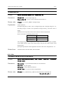
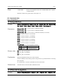
Trim
Format
object.Trim( <Threshold>, <Condition> )
Parameters
<Threshold> = VT_I4 : Threshold
<Condition> = VT_I4 : Condition
Return value
0
greater than
[point data] > <Threshold>
1
less than
[point data] < <Threshold>
<Area> =VT_I4|VT_ARRAY:Area of trimming
<X> = VT_I4 : X coordinate
<Y> = VT_I4 : Y coordinate
<W> = VT_I4 : Width
<H> = VT_I4 : Height
Explanation
Trim the area which fulfills the argument condition.
Color image is changed to grayscale image.
Return (-1, -1, -1, -1) value when area is wrong..
ORiN Forum
DENSO WAVE Inc.
OpenCV Provider User’s Guide
- 50 -
Related item
SearchPoint,SetROI
Example
[VB6]
‘ Trim the area with threshold value condition of more than 128.
vntParam = Array(128, 0)
vntRet = caoFile.Execute( “Trim”, vntParam )
x = vntRet(0) ‘ <X>
y = vntRet(1) ‘ <Y>
w = vntRet(2) ‘ <W>
h = vntRet(3) ‘ <H>
ImageSize
Format
object.ImageSize()
Parameters
None
Return value
<Size> = VT_I4|VT_ARRAY:Size of image.
<W> = VT_I4: Width of image
<H> = VT_I4: Height of image
Explanation
Get image size.
Example
[VB6]
vntRet = caoFile.Execute( “ImageSize” )
w = vntRet(0) ‘ <W>
h = vntRet(1) ‘ <H>
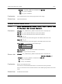
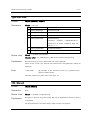
IsColor
[V1.3.5 or later]
Format
object.IsColor()
Parameters
None
Return value
<IsColor> = VT_BOOL:image color
Explanation
ORiN Forum
TRUE
Color image
FALSE
Gray scale image
Determine whther image is colored
DENSO WAVE Inc.
OpenCV Provider User’s Guide
- 51 -
IsEmpty
[V1.4.0 or later]
Format
object.IsEmpty()
Parameters
None
Return value
<IsEmpty> = VT_BOOL:Empty or not
Explanation
TRUE
Empty
FALSE
Not empty
Determine whether an image data is empty.
IsUpdated
[V1.4.0 or later]
Format
object.IsUpdated ()
Parameters
None
Return value
<IsUpdated> = VT_BOOL:The state of update of image data.
Explanation
TRUE
Updated(Default)
FALSE
nonupdated
Determine whether an image data is updated.
Execute "ClearUpdated" command, in order to change to nonupdate. An initial value
is Updated. Please use in combination with "ClearUpdated".
ClearUpdated
Format
object.ClearUpdated()
Parameters
None
Return value
None
Explanation
Clear the flag of update.
[V1.4.0 or later]
Distance
Format
object.Distance<Point1>, <Point2>
Parameters
<Point1> = VT_I4|VT_ARRAY: Coordinate point 1 (<X>,<Y>,<Z>)
<X> = VT_I4: X coordinate
ORiN Forum
DENSO WAVE Inc.
OpenCV Provider User’s Guide
- 52 -
<Y> = VT_I4: Y coordinate
<Z> = VT_I4: Z coordinate
<Point2> = VT_I4|VT_ARRAY: Coordinate point 2 (<X>,<Y>,<Z>)
<X> = VT_I4: X coordinate
<Y> = VT_I4: Y coordinate
<Z> = VT_I4: Z coordinate
Return value
<Distance> = VT_R8: Distance between two points
Explanation
Measure the distance between <Point1> and <Point2>.
InnerProduct
Format
object.InnerProduct <Vector1>, <Vector2>
Parameters
<Vector1> = VT_I4|VT_ARRAY: Vector 1 (<X>,<Y>,<Z>)
<X> = VT_I4: X
<Y> = VT_I4: Y
<Z> = VT_I4: Z
<Vector2> = VT_I4|VT_ARRAY: Vector 2 (<X>,<Y>,<Z>)
<X> = VT_I4: X
<Y> = VT_I4: Y
<Z> = VT_I4: Z
Return value
<Inner Product> = VT_R8: Inner product
Explanation
Calculate the inner product between <Vectore1> and <Vector2>.
OuterProduct
Format
object.OuterProduct <Vector1>, <Vector2>
Parameters
<Vector1> = VT_I4|VT_ARRAY: vector 1 (<X>,<Y>,<Z>)
<X> = VT_I4: X
<Y> = VT_I4: Y
<Z> = VT_I4: Z
<Vector2> = VT_I4|VT_ARRAY: vector 2 (<X>,<Y>,<Z>)
<X> = VT_I4: X
<Y> = VT_I4: Y
ORiN Forum
DENSO WAVE Inc.
OpenCV Provider User’s Guide
- 53 -
<Z> = VT_I4: Z
Return value
<Outer product> = VT_R8|VT_ARRAY: Outer product (<X>,<Y>,<Z>)
<X> = VT_I4: X
<Y> = VT_I4: Y
<Z> = VT_I4: Z
Explanation
Calculate the outer product between <Vector1> and <Vector2>.
PutHelp
Format
object.PutHelp <strHelp>
Parameters
<strHelp> = VT_BSTR: String
Return value
None
Explanation
Set a character string that can be obtained by CaoFile::get_Help.
This is not available for the raw image areas.
4.2.2. Edit
Copy
Format
object.Copy <Output ID>
Parameters
<Output ID> = VT_I4: Output Image ID
Return value
<Image> = VT_UI1|VT_ARRAY: Changed Image
Explanation
Copy image.
If Output Image ID=0, return value is changed image data. If Output Image Id <> 0,
the change image is stored in the specified ID image memory, and return value is
Empty.
The changed image data is output by the bitmap file format of the Windows standard.
Color output format is 24bit color bitmap image, and grayscale output format is 8bit
bitmap image.
Related item
ORiN Forum
Cut, Paste
DENSO WAVE Inc.
OpenCV Provider User’s Guide
- 54 -
Cut
Format
object.Cut <Output ID>, <X>, <Y>, <W>, <H>
Parameters
<Output ID> = VT_I4: Output Image ID
<X> = VT_I4: X coordinates
<Y> = VT_I4: Y coordinates
<W> = VT_I4: Width
<H> = VT_I4: Height
Return value
<Image> = VT_UI1|VT_ARRAY: Changed Image
Explanation
Cut image.
If Output Image ID=0, return value is changed image data. If Output Image Id <> 0,
the change image is stored in the specified ID image memory, and return value is
Empty.
The changed image data is output by the bitmap file format of the Windows standard.
Color output format is 24bit color bitmap image, and grayscale output format is 8bit
bitmap image.
Related item
Copy, Paste
Paste
Format
object.Paste <Output ID>, <Input ID>, <X>, <Y>
Parameters
<Output ID> = VT_I4: Output Image ID
<Input ID> = VT_I4: Putting Image ID
<X> = VT_I4: X Coordinates
<Y> = VT_I4: Y Coordinates
Return value
<Image> = VT_UI1|VT_ARRAY: Changed Image
Explanation
The image which be specified by <Input ID> is stuck on the image which be specified
by <Output ID>.
If Output Image ID=0, return value is changed image data. If Output Image Id <> 0,
the change image is stored in the specified ID image memory, and return value is
Empty.
The changed image data is output by the bitmap file format of the Windows standard.
Color output format is 24bits color bitmap image, and grayscale output format is 8bits
ORiN Forum
DENSO WAVE Inc.
OpenCV Provider User’s Guide
- 55 -
bitmap image.
Related item
Copy, Cut
Rotate
Format
object.Rotate <Output ID>, <X>, <Y>, <Angle>, <Flag>
Parameters
<Output ID> = VT_I4: Output Image ID
<X> = VT_I4: X Coordinates
<Y> = VT_I4: Y Coordinates
<Angle> = VT_I4: Rotating angle (degree)
<Flag> = VT_I4: Flag (<Warp>|<Interpolation>)
<Interpolation> =
0
CV_INTER_NN
nearest-neigbor interpolation.
1
CV_INTER_LINEAR
bilinear interpolation.
2
CV_INTER_AREA
resampling using pixel area relation. It is preferred
method for image decimation that gives moire-free
results. In case of zooming it is similar to
CV_INTER_NN method.
3
CV_INTER_CUBIC
bicubic interpolation.
<Warp> =
8
CV_WARP_FILL_OUTLIERS
Fill all the destination image pixels. If
some of them correspond to outliers in
the source image, they are set to 0.
16
CV_WARP_INVERSE_MAP
Indicates that matrix is inverse transform
from destination image to source and,
thus, can be used directly for pixel
interpolation. Otherwise, the function
finds the inverse transform from matrix.
Return value
<Image> = VT_UI1|VT_ARRAY: Changed Image
Explanation
Rotate image.
If Output Image ID=0, return value is changed image data. If Output Image Id <> 0,
the change image is stored in the specified ID image memory, and return value is
Empty.
The changed image data is output by the bitmap file format of the Windows standard.
ORiN Forum
DENSO WAVE Inc.
OpenCV Provider User’s Guide
- 56 -
Color output format is 24bit color bitmap image, and grayscale output format is 8bit
bitmap image.
[Note] From Version 1.3.5, rotation dilection is changed to crockwise.
Related item
Resize, Flip
Flip
Format
object.Flip <Output ID>, <Type>
Parameters
<Output ID> = VT_I4: Output Image ID
<Type> = VT_I4: Type
0
Flip around Y axis
1
Flip around X axis
2
Flip around both axes
Return value
<Image> = VT_UI1|VT_ARRAY: Changed Image
Explanation
Flip image.
If Output Image ID=0, return value is changed image data. If Output Image Id <> 0,
the change image is stored in the specified ID image memory, and return value is
Empty.
The changed image data is output by the bitmap file format of the Windows standard.
Color output format is 24bits color bitmap image, and grayscale output format is 8bits
bitmap image.
Related item
Resize, Rotate
Resize
Format
object.Resize <Output ID>, <W>, <H>, <Interpolation>
Parameters
<Output ID> = VT_I4: Output Image ID
<W> = VT_I4: Width
<H> = VT_I4: Height
<Interpolation> = VT_I4: Interpolation method
ORiN Forum
0
CV_INTER_NN
nearest-neigbor interpolation.
1
CV_INTER_LINEAR
bilinear interpolation.
2
CV_INTER_AREA
resampling using pixel area relation. It is preferred
DENSO WAVE Inc.
OpenCV Provider User’s Guide
- 57 method for image decimation that gives moire-free
results. In case of zooming it is similar to
CV_INTER_NN method.
3
CV_INTER_CUBIC
bicubic interpolation.
Return value
<Image> = VT_UI1|VT_ARRAY: Changed Image
Explanation
Resize image.
If Output Image ID=0, return value is changed image data. If Output Image Id <> 0,
the change image is stored in the specified ID image memory, and return value is
Empty.
The changed image data is output by the bitmap file format of the Windows standard.
Color output format is 24bit color bitmap image, and grayscale output format is 8bit
bitmap image.
Related item
Rotate, Flip
Split
Format
object.Split <Output ID(R)>, <Output ID(G)>, <Output ID(B)>
Parameters
<Output ID(R)> = VT_I4: Red Output Image ID
<Output ID(G)> = VT_I4: GreenOutput Image ID
<Output ID(B)> = VT_I4: Blue Output Image ID
Return value
<Images> = VT_VARIANT|VT_ARRAY: Splited image
(<Image(R)>,<Image(G)>,<Image(B)>)
<Image(R)> = VT_UI1|VT_ARRAY: Red image
<Image(G)> = VT_UI1|VT_ARRAY: Green image
<Image(B)> = VT_UI1|VT_ARRAY: Blue image
Explanation
Separate color image into three elements of RGB, and each element is output to
<Output ID(R)>, <Output ID(G)>, <Output ID(B)> respectively as greayscale images.
If input image is grayscale, an error is returned.
If Output Image ID=0, return value is changed image data. If Output Image Id <> 0,
the change image is stored in the specified ID image memory, and return value is
Empty.
The changed image data is output by the 8-bit bitmap file format of the Windows
standard.
ORiN Forum
DENSO WAVE Inc.
OpenCV Provider User’s Guide
Related item
- 58 -
Merge
Merge
Format
object.Merge <Output ID>, <InputID(R)>, <InputID(G)>, <InputID(B)>
Parameters
<Output ID> = VT_I4: Output Image ID
<InputID(R)> = VT_I4: Red Output Image ID
<InputID(G)> = VT_I4: Green Output Image ID
<InputID(B)> = VT_I4: Blue Output Image ID
Return value
<Image> = VT_UI1|VT_ARRAY: Changed Image
Explanation
Merge three gray scale images that correspond to R, G and B components of the color
image, and output a color image. The three component images are <InputID(R)>,
<InputID(G)>, <InputID(B)> and merged image output is <Output ID>.
If Output Image ID=0, return value is changed image data. If Output Image Id <> 0,
the change image is stored in the specified ID image memory, and return value is
Empty.
The changed image data is output by the 24-bit bitmap file format of the Windows
standard.
Related item
Split
4.2.3. Filter
ConvertGray
Format
object.ConvertGray <Output ID>
Parameters
<Output ID> = VT_I4: Output Image ID
Return value
<Image> = VT_UI1|VT_ARRAY: Changed Image
Explanation
Convert to gray scale.
If Output Image ID=0, return value is changed image data. If Output Image Id <> 0,
the change image is stored in the specified ID image memory, and return value is
Empty.
The changed image data is output by the 8-bit bitmap file format of the Windows
standard.
ORiN Forum
DENSO WAVE Inc.
OpenCV Provider User’s Guide
Example
- 59 -
[VB6]
caoFile.Execute “ConvertGray”, 101 ‘ Output to the 101st image.
ThresholdEx
Format
object.ThresholdEx <Output ID>, <Threshold>, <Max>, <Mode>
Parameters
<Output ID> = VT_I4: Output Image ID
<Threshold> = VT_I4: Threshold
<Max> = VT_I4: Maximum Value
<Mode> = VT_I4: Threshold process type
ORiN Forum
0
CV_THRESH_BINARY
1
CV_THRESH_BINARY_INV
2
CV_THRESH_TRUNC
3
CV_THRESH_TOZERO
4
CV_THRESH_TOZERO_INV
DENSO WAVE Inc.
OpenCV Provider User’s Guide
Return value
<Image> = VT_UI1|VT_ARRAY : Changed Image
Explanation
Threshold process.
- 60 -
Color image is automatically converted to grayscale image.
If Output Image ID=0, return value is changed image data. If Output Image Id <> 0,
the change image is stored in the specified ID image memory, and return value is
Empty.
The changed image data is output by the 8-bit bitmap file format of the Windows
standard.
Related item
Threshold2, AdaptiveThresholdEx
Threshold2
Format
object.Threshold2 <Output ID>, <Min>, <Max>
Parameters
<Output ID> = VT_I4: Output Image ID
<Min> = VT_I4: Lower bound threshold
<Max> = VT_I4: Upper bound threshold
Return value
<Image> = VT_UI1|VT_ARRAY: Changed Image
Explanation
Applies fixed-level threshold to array elements.
Color image is automatically converted to grayscale image.
If Output Image ID=0, return value is changed image data. If Output Image Id <> 0,
the change image is stored in the specified ID image memory, and return value is
Empty.
The changed image data is output by the 8-bit bitmap file format of the Windows
standard.
Related item
ORiN Forum
ThresholdEx, AdaptiveThresholdEx
DENSO WAVE Inc.
OpenCV Provider User’s Guide
- 61 -
AdaptiveThresholdEx
Format
object.AdaptiveThresholdEx <Output ID>, <Max value>, <Method>, <Type>,
<Block size>, <Parameter>
Parameters
<Output ID> = VT_I4: Output Image ID
<Max value> = VT_I4: Maximum Value
<Method> = VT_I4: Adaptive threshold algorithm type
0
CV_ADAPTIVE_THRESH_MEAN_C
1
CV_ADAPTIVE_THRESH_GAUSSIAN_C
<Type> = VT_I4: Threshold process type
0
CV_THRESH_BINARY
1
CV_THRESH_BINARY_INV
<Block size> = VT_I4: The size of a pixel neighborhood.(3,5,7,…)
<Parameter> = VT_R8: The method-dependent parameter
Return value
<Image> = VT_UI1|VT_ARRAY: Changed Image
Explanation
Adaptive threshold process.
Color image is automatically converted to grayscale image.
If Output Image ID=0, return value is changed image data. If Output Image Id <> 0,
the change image is stored in the specified ID image memory, and return value is
Empty.
The changed image data is output by the 8-bit bitmap file format of the Windows
standard.
Method option determines threshold calculation method, as shown in the table below.
CV_ADAPTIVE_THRESH_MEAN_C
It is a mean of <Block size> ×
<Block size> pixel neighborhood,
subtracted by <Parameter>.
CV_ADAPTIVE_THRESH_GAUSSIAN_C
It is a weighted sum (gaussian) of
<Block size> × <Block size>
pixel neighborhood, subtracted by
<Parameter>.
Related item
ORiN Forum
ThresholdEx, Threshold2
DENSO WAVE Inc.
OpenCV Provider User’s Guide
- 62 -
Smooth
Format
object.Smooth
<Output
ID>,
<Type>,
<Parameter1>,
<Parameter2>,
<Parameter3>, <Parameter4>
Parameters
<Output ID> = VT_I4: Output Image ID
<Type> = VT_I4: Smoothing type
0
CV_BLUR_NO_SCALE
summation over a pixel <Parameter1> ×
(simple blur with no
<Parameter2> neighborhood.
scaling)
1
CV_BLUR
summation over a pixel <Parameter1> ×
(simple blur)
<Parameter2>neighborhood with subsequent
scaling by 1/(<Parameter1>・<Pparameter2>).
2
3
CV_GAUSSIAN
convolving
image
(gaussian blur)
<Parameter2>Gaussian kernel.
CV_MEDIAN
finding
(median blur)
<Parameter1>neighborhood
median
with
of
<Parameter1>
<Parameter1>
(i.e.
×
×
the
neighborhood is square).
4
CV_BILATERAL
applying bilateral 3x3 filtering with color
(bilateral filter)
sigma=<Parameter1>and
space
sigma=<Parameter2>.
<Parameter1> = VT_I4: Parameter 1
<Parameter2> = VT_I4: Parameter 2
In case of simple scaled/non-scaled and Gaussian blur if <Parameter2> is zero, it
is set to <Parameter1>.
<Parameter3> = VT_I4: Parameter 3
In case of Gaussian kernel this parameter may specify Gaussian sigma (standard
deviation). If it is zero, it is calculated from the kernel size:
n
2
σ = − 1 × 0.3 + 0.8
where n=<Parameter1>for horizontal kernel,
n=<Parameter2>for vertical kernel.
With the standard sigma for small kernels (3×3 to 7×7) the performance is better.
If param3 is not zero, while param1 and param2 are zeros, the kernel size is
calculated from the sigma (to provide accurate enough operation).
<Parameter4> = VT_I4: Parameter 4
In case of non-square Gaussian kernel the parameter may be used to specify a
ORiN Forum
DENSO WAVE Inc.
OpenCV Provider User’s Guide
- 63 -
different (from param3) sigma in the vertical direction.
Return value
<Image> = VT_UI1|VT_ARRAY: Changed Image
Explanation
Smoothing. Parameters 1-4 have different meanings according to the conversion Type.
If Output Image ID=0, return value is changed image data. If Output Image Id <> 0,
the change image is stored in the specified ID image memory, and return value is
Empty.
The changed image data is output by the bitmap file format of the Windows standard.
Color output format is 24bit color bitmap image, and grayscale output format is 8bit
bitmap image.
Smoothing without scaling only supports gray scale images.
Other types of smoothing supports both grascale images and color images.
Sobel
Format
object.Sobel <Output ID>, <X order>, <Y order>, <Aperture>
Parameters
<Output ID> = VT_I4: Output Image ID
<X order> = VT_I4: X direction order
<Y order> = VT_I4: Y direction order
<Aperture> = VT_I4: Aperture size
Size of the extended Sobel kernel, must be 1, 3, 5 or 7. In all cases except 1,
<Aperture> × <Aperture> separable kernel will be used to calculate the derivative.
For aperture_size=1 3x1 or 1x3 kernel is used (Gaussian smoothing is not done).
There is also special value CV_SCHARR (=-1) that corresponds to 3x3 Scharr filter
that may give more accurate results than 3x3 Sobel. Scharr aperture is:
−3 0 3
− 10 0 10
−3 0 3
for x-derivative or transposed for y-derivative.
Return value
<Image> = VT_UI1|VT_ARRAY: Changed Image
Explanation
Sobel filter.
If Output Image ID=0, return value is changed image data. If Output Image Id <> 0,
the change image is stored in the specified ID image memory, and return value is
Empty.
ORiN Forum
DENSO WAVE Inc.
OpenCV Provider User’s Guide
- 64 -
The changed image data is output by the bitmap file format of the Windows standard.
Color output format is 24bits color bitmap image, and grayscale output format is 8bit
bitmap image.
This command calculates the image derivative by convolving the image with the
appropriate kernel:
dst ( x, y ) =
d XOrder +YOrder src
dx XOrder ⋅ dy YOrder
( x, y )
Laplace
Format
object.Laplace <Output ID>, <Aperture>
Parameters
<Output ID> = VT_I4: Output Image ID
<Aperture> = VT_I4: Aperture size
Size of the extended Sobel kernel, must be 1, 3, 5 or 7. (it has the same meaning
as in Sobel command).
Return value
<Image> = VT_UI1|VT_ARRAY: Changed Image
Explanation
Laplace filter.
If Output Image ID=0, return value is changed image data. If Output Image Id <> 0,
the change image is stored in the specified ID image memory, and return value is
Empty.
The changed image data is output by the bitmap file format of the Windows standard.
Color output format is 24bit color bitmap image, and grayscale output format is 8bit
bitmap image.
This command calculates Laplacian of the source image by summing second x- and yderivatives calculated using Sobel operator:
dst ( x, y ) =
d 2 src d 2 src
+
dx 2
dy 2
Specifying <Aperture>=1 gives the fastest variant that is equal to convolving the
image with the following kernel:
0 1 0
1 − 4 1
0 1 0
ORiN Forum
DENSO WAVE Inc.
OpenCV Provider User’s Guide
- 65 -
CannyEx
Format
object.CannyEx <Output ID>, <Threshold1>, <Threshold2>, <Aperture>
Parameters
<Output ID> = VT_I4: Output Image ID
<Threshold1> = VT_I4: Threshold 1
<Threshold2> = VT_I4: Threshold 2
<Aperture> = VT_I4: Aperture size
Size of the extended Sobel kernel, must be 3, 5 or 7.
(it has the same meaning as
in Sobel command).
Return value
<Image> = VT_UI1|VT_ARRAY: Changed Image
Explanation
Canny filter.
Color image is automatically converted to grayscale image.
If Output Image ID=0, return value is changed image data. If Output Image Id <> 0,
the change image is stored in the specified ID image memory, and return value is
Empty.
The changed image data is output by the 8-bit bitmap file format of the Windows
standard.
The smallest of <Threshold1> and <Threshold2> is used for edge linking, the largest to find initial segments of strong edges.
WarpAffine
Format
object.WarpAffine <Output ID>, <Ax>, <Bx>, <Dx>, <Ay>, <By>, <Dy>, <Flag>
Parameters
<Output ID> = VT_I4: Output Image ID
<Ax> = VT_I4: Affine transformation matrix
<Bx>
<Dx>
<Ay>
<By>
<Dy>
Ax
Ay
Bx
By
Dx
Dy
<Flag> = VT_I4: Flag (<Warp>|<Interpolation>)
<Interpolation> =
0
ORiN Forum
CV_INTER_NN
nearest-neigbor interpolation.
DENSO WAVE Inc.
OpenCV Provider User’s Guide
- 66 -
1
CV_INTER_LINEAR
bilinear interpolation.
2
CV_INTER_AREA
resampling using pixel area relation. It is preferred
method for image decimation that gives moire-free
results. In case of zooming it is similar to
CV_INTER_NN method.
3
CV_INTER_CUBIC
bicubic interpolation.
<Warp> =
8
CV_WARP_FILL_OUTLIERS
Fill all the destination image pixels. If
some of them correspond to outliers in
the source image, they are set to 0.
16
CV_WARP_INVERSE_MAP
Indicates that matrix is inverse transform
from destination image to source and,
thus, can be used directly for pixel
interpolation. Otherwise, the function
finds the inverse transform from matrix.
Return value
<Image> = VT_UI1|VT_ARRAY: Changed Image
Explanation
Affine transformation.
If Output Image ID=0, return value is changed image data. If Output Image Id <> 0,
the change image is stored in the specified ID image memory, and return value is
Empty.
The changed image data is output by the bitmap file format of the Windows standard.
Color output format is 24bit color bitmap image, and grayscale output format is 8bit
bitmap image.
WarpPerspective
Format
object.WarpPerspective<Output ID>, <Extrinsic matrix>, <Flag>
Parameters
<Output ID> = VT_I4:Output Image ID
<Extrinsic matrix> = VT_R8|VT_ARRAY:Transformation matrix
(<r11>,<r21>,<r31>,<r12>,<r22>,<r32>,<r13>,<r23>,<r33>)
<r11> = VT_R8:
<r21> = VT_R8:
<r31> = VT_R8:
<r12> = VT_R8:
ORiN Forum
DENSO WAVE Inc.
OpenCV Provider User’s Guide
- 67 -
<r22> = VT_R8:
<r32> = VT_R8:
<r13> = VT_R8:
<r23> = VT_R8:
<r33> = VT_R8:
r11 r12 r13
r 21 r 22 r 23
r 31 r 32 r 33
<Flag> = VT_I4:Flag (<Warp>|<Interpolation>)
<Interpolation> =
0
CV_INTER_NN
nearest-neigbor interpolation.
1
CV_INTER_LINEAR
bilinear interpolation.
2
CV_INTER_AREA
resampling using pixel area relation. It is preferred
method for image decimation that gives moire-free
results. In case of zooming it is similar to
CV_INTER_NN method.
3
CV_INTER_CUBIC
bicubic interpolation.
<Warp> =
8
CV_WARP_FILL_OUTLIERS
Fill all the destination image pixels. If
some of them correspond to outliers in
the source image, they are set to 0.
16
CV_WARP_INVERSE_MAP
Indicates that matrix is inverse transform
from destination image to source and,
thus, can be used directly for pixel
interpolation. Otherwise, the function
finds the inverse transform from matrix.
Return value
<Image> = VT_UI1|VT_ARRAY:Changed Image
Explanation
Calculate perspective transformation.
When output image number is 0, the transformed image is output to return value.
When output image number is not 0, the transformed image is output to the specified
number ID image, and return value becomes Empty.
The transformed image output data is Windows standard bitmap file format. Color
output format is 24bit color bitmap image, and grayscale output format is 8bit bitmap
image.
ORiN Forum
DENSO WAVE Inc.
OpenCV Provider User’s Guide
- 68 -
PreCornerDetectEx
Format
object.PreCornerDetectEx <Output ID>, <Aperture>
Parameters
<Output ID> = VT_I4: Output Image ID
<Aperture> = VT_I4: Aperture size
Size of the extended Sobel kernel, must be 3, 5 or 7.
(it has the same meaning as
in Sobel command).
Return value
<Image> = VT_UI1|VT_ARRAY: Changed Image
Explanation
Corner detector.
Color image is automatically converted to grayscale image.
If Output Image ID=0, return value is changed image data. If Output Image Id <> 0,
the change image is stored in the specified ID image memory, and return value is
Empty.
The changed image data is output by the 8-bit bitmap file format of the Windows
standard.
This command calculates the function
D x D yy + D y D xx − 2 D x D y D xy
2
2
where D? denotes one of the first image derivatives and D?? denotes a second image
derivative. The corners can be found as local maximums of the function.
CornerHarrisEx
Format
object.CornerHarrisEx <Output ID>, <Block size>, <Aperture>, <K>
Parameters
<Output ID> = VT_I4: Output Image ID
<Block size> = VT_I4: Block size
<Aperture> = VT_I4: Aperture size
Size of the extended Sobel kernel, must be 3, 5 or 7.
(it has the same meaning as
in Sobel command).
<K> = VT_R8: free variable
Return value
ORiN Forum
<Image> = VT_UI1|VT_ARRAY: Changed Image
DENSO WAVE Inc.
OpenCV Provider User’s Guide
Explanation
- 69 -
Harris edge detector.
Color image is automatically converted to grayscale image.
If Output Image ID=0, return value is changed image data. If Output Image Id <> 0,
the change image is stored in the specified ID image memory, and return value is
Empty.
The changed image data is output by the 8-bit bitmap file format of the Windows
standard.
CalcBackProjectEx
Format
object.CalcBackProjectEx <Output ID>, <Input ID>
Parameters
<Output ID> = VT_I4: Output Image ID
<Input ID> = VT_I4: Input image ID
Return value
<Image> = VT_UI1|VT_ARRAY: Changed Image
Explanation
Calculate back projection.
Creates histogram from input image, and calculate back projection.
If Output Image ID=0, return value is changed image data. If Output Image Id <> 0,
the change image is stored in the specified ID image memory, and return value is
Empty.
The changed image data is output by the 8-bit bitmap file format of the Windows
standard.
Inpaint
Format
object.Inpaint <Output ID>, <MaskID>, <Range>, <Flag>
Parameters
<Output ID> = VT_I4: Output Image ID
<MaskID> = VT_I4: Mask Image ID
gray scale. Non-zero pixels indicate the area that needs to be inpainted.
<Range> = VT_I4: Adjacent area
<Flag> = VT_I4: Repair method
Return value
ORiN Forum
0
CV_INPAINT_NS
Navier-Stokes based method.
1
CV_INPAINT_TELEA
The method by Alexandru Telea.
<Image> = VT_UI1|VT_ARRAY: Changed Image
DENSO WAVE Inc.
OpenCV Provider User’s Guide
Explanation
- 70 -
Repair image.
As for the mask data, the brightness of < MaskID > image is made from the value of
one or more.
Color image is automatically converted to grayscale image.
If Output Image ID=0, return value is changed image data. If Output Image Id <> 0,
the change image is stored in the specified ID image memory, and return value is
Empty.
The changed image data is output by the bitmap file format of the Windows standard.
Color output format is 24bit color bitmap image, and grayscale output format is 8bit
bitmap image.
Erode
Format
object.Erode <Output ID>, <Iterations>, <Cols>, <Rows>, <AnchorX>,
<AnchorY>, <Shape>
Parameters
<Output ID> = VT_I4: Output image number
<Iterations> = VT_I4: Number of times erosion is applied
<Cols> = VT_I4: Columns of structuring element
<Rows> = VT_I4: Rows of structuring element
<Anchor X> = VT_I4: Horizontal relative offset of anchor point
<Anchor Y> = VT_I4: Vertical relative offset of anchor point
<Shape> = VT_I4: Structuring element shape
0
CV_SHAPE_RECT
A rectangular element
1
CV_SHAPE_CROSS
A cross-shaped element
2
CV_SHAPE_ELLIPSE
An elliptic element
Return value
<Image> = VT_UI1|VT_ARRAY: Converted image
Explanation
Erodes the image using the specified structuring element that determines the shape of a
pixel neighborhood over which the minimum is taken
If Output Image ID=0, return value is changed image data. If Output Image Id <> 0,
the change image is stored in the specified ID image memory, and return value is
Empty.
The changed image data is output by the bitmap file format of the Windows standard.
Color output format is 24bit color bitmap image, and grayscale output format is 8bit
bitmap image.
ORiN Forum
DENSO WAVE Inc.
OpenCV Provider User’s Guide
Related item
- 71 -
Dilate
Dilate
Format
object.Dilate <Output ID>, <Iterations>, <Cols>, <Rows>, <AnchorX>,
<AnchorY>, <Shape>
Parameters
<Output ID> = VT_I4: Output image number
<Iterations> = VT_I4: Number of times erosion is applied
<Cols> = VT_I4: Columns of structuring element
<Rows> = VT_I4: Rows of structuring element
<Anchor X> = VT_I4: Horizontal relative offset of anchor point
<Anchor Y> = VT_I4: Vertical relative offset of anchor point
<Shape> = VT_I4: Structuring element shape
0
CV_SHAPE_RECT
A rectangular element
1
CV_SHAPE_CROSS
A cross-shaped element
2
CV_SHAPE_ELLIPSE
An elliptic element
Return value
<Image> = VT_UI1|VT_ARRAY: Converted image
Explanation
Dilates the image using the specified structuring element that determines the shape of a
pixel neighborhood over which the maximum is taken.
If Output Image ID=0, return value is changed image data. If Output Image Id <> 0,
the change image is stored in the specified ID image memory, and return value is
Empty.
The changed image data is output by the bitmap file format of the Windows standard.
Color output format is 24bit color bitmap image, and grayscale output format is 8bit
bitmap image.
Related item
Erode
PyrDown
Format
object.PyrDown <Output ID>
Parameters
<Output ID> = VT_I4: Output image number
Return value
<Image> = VT_UI1|VT_ARRAY: Converted image
ORiN Forum
DENSO WAVE Inc.
OpenCV Provider User’s Guide
Explanation
- 72 -
Performs downsampling step of Gaussian pyramid decomposition. First it convolves
source image with the specified filter and then downsamples the image by rejecting
even rows and columns.
The width and height of output image becomes half of input image.
When output image number is 0, transferred image is output to return value.
When output image is not 0, transferred image is output to the specified number, and
return value.
The changed image data is output by the bitmap file format of the Windows standard.
Color output format is 24bit color bitmap image, and grayscale output format is 8bit
bitmap image.
Related item
PyrUp
PyrUp
Format
object.PyrUp <Output ID>
Parameters
<Output ID> = VT_I4: Output image number
Return value
<Image> = VT_UI1|VT_ARRAY: Converted image
Explanation
performs up-sampling step of Gaussian pyramid decomposition. First it upsamples the
source image by injecting even zero rows and columns and then convolves result with
the specified filter multiplied by 4 for interpolation. So the destination image is four
times larger than the source image.
The width and height of output image is doubled from the input image.
When output image number is 0, transferred image is output to return value.
When output image is not 0, transferred image is output to the specified number, and
return value.
The changed image data is output by the bitmap file format of the Windows standard.
Color output format is 24bit color bitmap image, and grayscale output format is 8bit
bitmap image.
Related item
ORiN Forum
PyrDown
DENSO WAVE Inc.
OpenCV Provider User’s Guide
- 73 -
4.2.4. Mask
NOT
Format
object.NOT <Output ID>
Parameters
<Output ID> = VT_I4: Output Image ID
Return value
<Image> = VT_UI1|VT_ARRAY: Changed Image
Explanation
Bit inversion.
If Output Image ID=0, return value is changed image data. If Output Image Id <> 0,
the change image is stored in the specified ID image memory, and return value is
Empty.
The changed image data is output by the bitmap file format of the Windows standard.
Color output format is 24bit color bitmap image, and grayscale output format is 8bit
bitmap image.
Related item
AND, OR, XOR, ADD, SUB, MAXEx, MINEx, ABS
AND
Format
object.AND <Output ID>, <InputID>
Parameters
<Output ID> = VT_I4: Output Image ID
<InputID> = VT_I4: Input Image ID
Return value
<Image> = VT_UI1|VT_ARRAY: Changed Image
Explanation
Logical AND.
If Output Image ID=0, return value is changed image data. If Output Image Id <> 0,
the change image is stored in the specified ID image memory, and return value is
Empty.
The changed image data is output by the bitmap file format of the Windows standard.
Color output format is 24bit color bitmap image, and grayscale output format is 8bit
bitmap image.
Related item
ORiN Forum
NOT, OR, XOR, ADD, SUB, MAXEx, MINEx, ABS
DENSO WAVE Inc.
OpenCV Provider User’s Guide
- 74 -
OR
Format
object.OR <Output ID>, <InputID>
Parameters
<Output ID> = VT_I4: Output Image ID
<InputID> = VT_I4: Input Image ID
Return value
<Image> = VT_UI1|VT_ARRAY: Changed Image
Explanation
Logical OR.
If Output Image ID=0, return value is changed image data. If Output Image Id <> 0,
the change image is stored in the specified ID image memory, and return value is
Empty.
The changed image data is output by the bitmap file format of the Windows standard.
Color output format is 24bit color bitmap image, and grayscale output format is 8bit
bitmap image.
Related item
NOT, AND, XOR, ADD, SUB, MAXEx, MINEx, ABS
XOR
Format
object.XOR <Output ID>, <InputID>
Parameters
<Output ID> = VT_I4: Output Image ID
<InputID> = VT_I4: Input Image ID
Return value
<Image> = VT_UI1|VT_ARRAY: Changed Image
Explanation
Logical Exclusive-OR.
If Output Image ID=0, return value is changed image data. If Output Image Id <> 0,
the change image is stored in the specified ID image memory, and return value is
Empty.
The changed image data is output by the bitmap file format of the Windows standard.
Color output format is 24bit color bitmap image, and grayscale output format is 8bit
bitmap image.
Related item
ORiN Forum
NOT, AND, OR, ADD, SUB, MAXEx, MINEx, ABS
DENSO WAVE Inc.
OpenCV Provider User’s Guide
- 75 -
ADD
Format
object.ADD <Output ID>, <InputID>
Parameters
<Output ID> = VT_I4: Output Image ID
<InputID> = VT_I4: Input Image ID
Return value
<Image> = VT_UI1|VT_ARRAY: Changed Image
Explanation
Addition.
If Output Image ID=0, return value is changed image data. If Output Image Id <> 0,
the change image is stored in the specified ID image memory, and return value is
Empty.
The changed image data is output by the bitmap file format of the Windows standard.
Color output format is 24bit color bitmap image, and grayscale output format is 8bit
bitmap image.
Related item
NOT, AND, OR, XOR,, SUB, MAXEx, MINEx, ABS
SUB
Format
object.SUB <Output ID>, <InputID>
Parameters
<Output ID> = VT_I4: Output Image ID
<InputID> = VT_I4: Input Image ID
Return value
<Image> = VT_UI1|VT_ARRAY: Changed Image
Explanation
Subtraction.
If Output Image ID=0, return value is changed image data. If Output Image Id <> 0,
the change image is stored in the specified ID image memory, and return value is
Empty.
The changed image data is output by the bitmap file format of the Windows standard.
Color output format is 24bit color bitmap image, and grayscale output format is 8bit
bitmap image.
Related item
ORiN Forum
NOT, AND, OR, XOR, ADD, MAXEx, MINEx, ABS
DENSO WAVE Inc.
OpenCV Provider User’s Guide
- 76 -
MAXEx
Format
object.MAXEx <Output ID>, <InputID>
Parameters
<Output ID> = VT_I4: Output Image ID
<InputID> = VT_I4: Input Image ID
Return value
<Image> = VT_UI1|VT_ARRAY: Changed Image
Explanation
Maximum value.
Color image is automatically converted to grayscale image.
If Output Image ID=0, return value is changed image data. If Output Image Id <> 0,
the change image is stored in the specified ID image memory, and return value is
Empty.
The changed image data is output by the bitmap file format of the Windows standard.
Color output format is 24bit color bitmap image, and grayscale output format is 8bit
bitmap image.
Related item
NOT, AND, OR, XOR, ADD, SUB, MINEx, ABS
MINEx
Format
object.MINEx <Output ID>, <InputID>
Parameters
<Output ID> = VT_I4: Output Image ID
<InputID> = VT_I4: Input Image ID
Return value
<Image> = VT_UI1|VT_ARRAY: Changed Image
Explanation
Minimum value.
Color image is automatically converted to grayscale image.
If Output Image ID=0, return value is changed image data. If Output Image Id <> 0,
the change image is stored in the specified ID image memory, and return value is
Empty.
The changed image data is output by the bitmap file format of the Windows standard.
Color output format is 24bit color bitmap image, and grayscale output format is 8bit
bitmap image.
Related item
ORiN Forum
NOT, AND, OR, XOR, ADD, SUB, MAXEx, ABS
DENSO WAVE Inc.
OpenCV Provider User’s Guide
- 77 -
ABS
Format
object.ABS <Output ID>, <InputID>
Parameters
<Output ID> = VT_I4: Output Image ID
<InputID> = VT_I4: Input Image ID
Return value
<Image> = VT_UI1|VT_ARRAY: Changed Image
Explanation
Absolute value.
If Output Image ID=0, return value is changed image data. If Output Image Id <> 0,
the change image is stored in the specified ID image memory, and return value is
Empty.
The changed image data is output by the bitmap file format of the Windows standard.
Color output format is 24bit color bitmap image, and grayscale output format is 8bit
bitmap image.
Related item
NOT, AND, OR, XOR, ADD, SUB, MAXEx, MINEx
LUT
[V1.3.5 or later]
Format
object.LUT <Output ID>, <LUT ID>
Parameters
<Output ID> = VT_I4: Output Image ID
<LUT ID> = VT_I4:Lookup table number
Return value
<Image> = VT_UI1|VT_ARRAY: Changed Image
Explanation
Apply lookup table conversion to <InputID> image, and the converted image is output
to <Output ID> or return value.
When <InputID> image is color, each hue is converted using corresponding lookup
table.
When <InputID> image is grayscal,e the image is converted using blue hue table.
If Output Image ID=0, return value is changed image data. If Output Image Id <> 0,
the change image is stored in the specified ID image memory, and return value is
Empty.
The changed image data is output by the bitmap file format of the Windows standard.
Color output format is 24bit color bitmap image, and grayscale output format is 8bit
bitmap image.
ORiN Forum
DENSO WAVE Inc.
OpenCV Provider User’s Guide
Related item
- 78 -
SetLUT, GetLUT
SetLUT
[V1.3.5 or later]
Format
object.SetLUT <LUT ID>, <Table R>, <Table G>, <Table B>
Parameters
<LUT ID> = VT_I4: Lookup table number
<Table R> = VT_UI1|VT_ARRAY: Red hue lookup table
<Table G> = VT_UI1|VT_ARRAY: Green hue lookup table
<Table B> = VT_UI1|VT_ARRAY: Blue hue lookup table
Return value
<Image> = VT_UI1|VT_ARRAY: Changed Image
Explanation
Setup the specified lookup table.
Each hue table requires 256 pixels.
When hue table is not specified and VT_EMPTY is used instead, the table content is
not changed.
Related item
LUT, GetLUT
GetLUT
[V1.3.5 or later]
Format
object.GetLUT <LUT ID>
Parameters
<LUT ID> = VT_I4: Lookup table number
Return value
<LUT> = VT_VARIANT|VT_ARRRAY: Lookup table
(<Table R>, <Table G>, <Table B>)
<Table R> = VT_UI1|VT_ARRAY: Red hue lookup table
<Table G> = VT_UI1|VT_ARRAY: Green hue lookup table
<Table B> = VT_UI1|VT_ARRAY: Blue hue lookup table
Explanation
Get the specified lookup table.
Related item
LUT, SetLUT
ORiN Forum
DENSO WAVE Inc.
OpenCV Provider User’s Guide
- 79 -
4.2.5. Draw
Line
Format
object.Line <Output ID>, <StartX>, <StartY>, <End X>, <End Y>, <R>, <G>,
<B>, <Thick>, <Type>
Parameters
<Output ID> = VT_I4: Output Image ID
<StartX> = VT_I4: Start point X coordinates
<StartY> = VT_I4: Start point Y coordinates
<End X> = VT_I4: End point X coordinates
<End Y> = VT_I4: End point Y coordinates
<R> = VT_I4: Red density
<G> = VT_I4: Green density
<B> = VT_I4: Blue density
<Thick> = VT_I4: Thickness
<Type> = VT_I4: Line type
0,8
8-connected line.
4
4-connected line.
16
antialiased line.
Return value
<Image> = VT_UI1|VT_ARRAY: Changed Image
Explanation
Draw a line (between two specified points).
For grayscale image, the drawing brightness is set to the value of <B>.
If Output Image ID=0, return value is changed image data. If Output Image Id <> 0,
the change image is stored in the specified ID image memory, and return value is
Empty.
The changed image data is output by the bitmap file format of the Windows standard.
Color output format is 24bit color bitmap image, and grayscale output format is 8bit
bitmap image.
Related item
Line2
Line2
Format
object.Line2 <Output ID>, <StartX>, <StartY>, <Length>, <Rotate>, <R>,
<G>, <B>, <Thick>, <Type>
ORiN Forum
DENSO WAVE Inc.
OpenCV Provider User’s Guide
Parameters
- 80 -
<Output ID> = VT_I4: Output Image ID
<StartX> = VT_I4: Start point X coordinates
<StartY> = VT_I4: Start point Y coordinates
<Length> = VT_I4: Length
<Angle> = VT_I4: Rotating angle (degree)
<R> = VT_I4: Red density
<G> = VT_I4: Green density
<B> = VT_I4: Blue density
<Thick> = VT_I4: Thickness
<Type> = VT_I4: Line type
0,8
8-connected line.
4
4-connected line.
16
antialiased line.
Return value
<Image> = VT_UI1|VT_ARRAY: Changed Image
Explanation
Draw a line (length specified).
For grayscale image, the drawing brightness is set to the value of <B>.
If Output Image ID=0, return value is changed image data. If Output Image Id <> 0,
the change image is stored in the specified ID image memory, and return value is
Empty.
The changed image data is output by the bitmap file format of the Windows standard.
Color output format is 24bit color bitmap image, and grayscale output format is 8bit
bitmap image.
[Note] From Version 1.3.5, rotation dilection is changed to crockwise.
Related item
Line
Rectangle
Format
object.Rectangle <Output ID>, <StartX>, <StartY>, <End X>, <End Y>, <R>,
<G>, <B>, <Thick>, <Type>
Parameters
<Output ID> = VT_I4: Output Image ID
<StartX> = VT_I4: Start point X coordinates
<StartY> = VT_I4: Start point Y coordinates
<End X> = VT_I4: End point X coordinates
<End Y> = VT_I4: End point Y coordinates
ORiN Forum
DENSO WAVE Inc.
OpenCV Provider User’s Guide
- 81 -
<R> = VT_I4: Red density
<G> = VT_I4: Green density
<B> = VT_I4: Blue density
<Thick> = VT_I4: Thickness
<Type> = VT_I4: Line type
0,8
8-connected line.
4
4-connected line.
16
antialiased line.
Return value
<Image> = VT_UI1|VT_ARRAY: Changed Image
Explanation
Draw a rectangle.
For grayscale image, the drawing brightness is set to the value of <B>.
If Output Image ID=0, return value is changed image data. If Output Image Id <> 0,
the change image is stored in the specified ID image memory, and return value is
Empty.
The changed image data is output by the bitmap file format of the Windows standard.
Color output format is 24bit color bitmap image, and grayscale output format is 8bit
bitmap image.
Circle
Format
object.Circle <Output ID>, <X>, <Y>, <Radius>, <R>, <G>, <B>, <Thick>,
<Type>
Parameters
<Output ID> = VT_I4: Output Image ID
<X> = VT_I4: center X coordinates
<Y> = VT_I4: center Y coordinates
<Radius> = VT_I4: radius
<R> = VT_I4: red density
<G> = VT_I4: green density
<B> = VT_I4: blue density
<Thick> = VT_I4: thickness
<Type> = VT_I4: line type
ORiN Forum
0,8
8-connected line.
4
4-connected line.
16
antialiased line.
DENSO WAVE Inc.
OpenCV Provider User’s Guide
- 82 -
Return value
<Image> = VT_UI1|VT_ARRAY: Changed Image
Explanation
Draw a circle.
For grayscale image, the drawing brightness is set to the value of <B>.
If Output Image ID=0, return value is changed image data. If Output Image Id <> 0,
the change image is stored in the specified ID image memory, and return value is
Empty.
The changed image data is output by the bitmap file format of the Windows standard.
Color output format is 24bit color bitmap image, and grayscale output format is 8bit
bitmap image.
Ellipse
Format
object.Ellipse <Output ID>, <X>, <Y>, <XRadius>, <YRadius>, <Angle>,
<Start angle>, <End angle>, <R>, <G>, <B>, <Thick>, <Type>
Parameters
<Output ID> = VT_I4: Output Image ID
<X> = VT_I4: Center point X coordinates
<Y> = VT_I4: Center point Y coordinates
<XRadius> = VT_I4: Radius of X axis
<YRadius> = VT_I4: Radius of Y axis
<Angle> = VT_I4: Rotate angle (degree)
<Start angle> = VT_I4: Start angle (degree)
<End angle> = VT_I4: End angle (degree)
<R> = VT_I4: red density
<G> = VT_I4: green density
<B> = VT_I4: blue density
<Thick> = VT_I4: thickness
<Type> = VT_I4: line type
0,8
8-connected line.
4
4-connected line.
16
antialiased line.
Return value
<Image> = VT_UI1|VT_ARRAY: Changed Image
Explanation
Draw an ellipse.
For grayscale image, the drawing brightness is set to the value of <B>.
If Output Image ID=0, return value is changed image data. If Output Image Id <> 0,
ORiN Forum
DENSO WAVE Inc.
OpenCV Provider User’s Guide
- 83 -
the change image is stored in the specified ID image memory, and return value is
Empty.
The changed image data is output by the bitmap file format of the Windows standard.
Color output format is 24bit color bitmap image, and grayscale output format is 8bit
bitmap image.
Please see the Ellipse function in the OpenCV reference for the details.
[Note] From Version 1.3.5, rotation dilection is changed to crockwise..
Sector
Format
object.Sector <Output ID>, <X>, <Y>, <XRadius>, <YRadius>, <Angle>,
<Start angle>, <End angle>, <R>, <G>, <B>, <Thick>, <Type>
Parameters
<Output ID> = VT_I4: Output Image ID
<X> = VT_I4: Center point X coordinates
<Y> = VT_I4: Center point Y coordinates
<XRadius> = VT_I4: Radius of X axis
<YRadius> = VT_I4: Radius of Y axis
<Angle> = VT_I4: Rotate angle degree
<Start angle> = VT_I4: Start angle degree
<End angle> = VT_I4: End angle degree
<R> = VT_I4: red density
<G> = VT_I4: green density
<B> = VT_I4: blue density
<Thick> = VT_I4: thickness
<Type> = VT_I4: line type
0,8
8-connected line.
4
4-connected line.
16
antialiased line.
Return value
<Image> = VT_UI1|VT_ARRAY: Changed Image
Explanation
Fill eclipse sector.
For grayscale image, the drawing brightness is set to the value of <B>.
If Output Image ID=0, return value is changed image data. If Output Image Id <> 0,
the change image is stored in the specified ID image memory, and return value is
Empty.
The changed image data is output by the bitmap file format of the Windows standard.
ORiN Forum
DENSO WAVE Inc.
OpenCV Provider User’s Guide
- 84 -
Color output format is 24bit color bitmap image, and grayscale output format is 8bit
bitmap image.
[Note] From Version 1.3.5, rotation dilection is changed to crockwise.
Cross
Format
object.Cross <Output ID>, <X>, <Y>, <XSize>, <YSize>, <Angle>, <R>, <G>,
<B>, <Thick>, <Type>
Parameters
<Output ID> = VT_I4: Output Image ID
<X> = VT_I4: Start point X coordinates
<Y> = VT_I4: Start point Y coordinates
<XSize> = VT_I4: Size of X axis
<YSize> = VT_I4: Size of Y axis
<Angle> = VT_I4: Rotate angle degree
<R> = VT_I4: red density
<G> = VT_I4: green density
<B> = VT_I4: blue density
<Thick> = VT_I4: thickness
<Type> = VT_I4: line type
0,8
8-connected line.
4
4-connected line.
16
antialiased line.
Return value
<Image> = VT_UI1|VT_ARRAY: Changed Image
Explanation
Cross drawing.
For grayscale image, the drawing brightness is set to the value of <B>.
If Output Image ID=0, return value is changed image data. If Output Image Id <> 0,
the change image is stored in the specified ID image memory, and return value is
Empty.
The changed image data is output by the bitmap file format of the Windows standard.
Color output format is 24bit color bitmap image, and grayscale output format is 8bit
bitmap image.
[Note] From Version 1.3.5, rotation dilection is changed to crockwise.
ORiN Forum
DENSO WAVE Inc.
OpenCV Provider User’s Guide
- 85 -
Text
Format
object.Text <Output ID>, <X>, <Y>, <Text>, <R>, <G>, <B>, <Font>,
<HScale>, <VScale>, <Shear>, <Thick>
Parameters
<Output ID> = VT_I4: Output Image ID
<X> = VT_I4: Start point X coordinates
<Y> = VT_I4: Start point Y coordinates
<Text> = VT_BSTR: Displayed text
<R> = VT_I4: Red density
<G> = VT_I4: Green density
<B> = VT_I4: Blue density
<Font> = VT_I4: Font type
0
CV_FONT_HERSHEY_
normal size sans-serif font
SIMPLEX
1
CV_FONT_HERSHEY_
small size sans-serif font
PLAIN
2
3
CV_FONT_HERSHEY_
normal size sans-serif font (more complex than
DUPLEX
CV_FONT_HERSHEY_SIMPLEX)
CV_FONT_HERSHEY_
normal size serif font
COMPLEX
4
5
6
CV_FONT_HERSHEY_
normal size serif font (more complex than
TRIPLEX
CV_FONT_HERSHEY_COMPLEX)
CV_FONT_HERSHEY_
smaller
COMPLEX_SMALL
CV_FONT_HERSHEY_COMPLEX
CV_FONT_HERSHEY_
hand-writing style font
version
of
SCRIPT_SIMPLEX
7
CV_FONT_HERSHEY_
more
complex
variant
SCRIPT_COMPLEX
CV_FONT_HERSHEY_SCRIPT_SIMPLEX
of
<HScale> = VT_R8: Width ratio
If equal to 1.0f, the characters have the original width depending on the font type.
If equal to 0.5f, the characters are of half the original width.
<VScale> = VT_R8: Height ratio
If equal to 1.0f, the characters have the original height depending on the font type.
If equal to 0.5f, the characters are of half the original height.
<Shear> = VT_R8: Relative angle from perpendicular line
Zero value means a non-italic font, 1.0f means ≈45° slope, etc. thickness
ORiN Forum
DENSO WAVE Inc.
OpenCV Provider User’s Guide
- 86 -
Thickness of lines composing letters outlines. The function cvLine is used for
drawing letters.
<Thick> = VT_I4: Thickness
Return value
<Image> = VT_UI1|VT_ARRAY: Changed Image
Explanation
Display character string.
For grayscale image, the drawing brightness is set to the value of <B>.
< Shear > is 0 degrees by 0.0, and 45 degrees by 1.0.
If Output Image ID=0, return value is changed image data. If Output Image Id <> 0,
the change image is stored in the specified ID image memory, and return value is
Empty.
The changed image data is output by the bitmap file format of the Windows standard.
Color output format is 24bit color bitmap image, and grayscale output format is 8bit
bitmap image.
4.2.6. Contours
FindContoursEx
Format
object.FindContoursEx( <Mode>, <Method> )
Parameters
<Mode> = VT_I4: Retrieval mode
0
CV_RETR_EXTERNAL
retrive only the extreme outer contours
1
CV_RETR_LIST
retrieve all the contours and puts them in the list
2
CV_RETR_CCOMP
retrieve all the contours and organizes them into
two-level hierarchy: top level are external
boundaries of the components, second level are
bounda boundaries of the holes
3
CV_RETR_TREE
retrieve all the contours and reconstructs the full
hierarchy of nested contours
<Method> = VT_I4: Approximation method
0
CV_CHAIN_CODE
output contours in the Freeman chain code. All
other methods output polygons (sequences of
vertices).
1
2
ORiN Forum
CV_CHAIN_APPROX_
translate all the points from the chain code into
NONE
points;
CV_CHAIN_APPROX_S
compress horizontal, vertical, and diagonal
DENSO WAVE Inc.
OpenCV Provider User’s Guide
- 87 -
IMPLE
segments, that is, the function leaves only their
ending points;
3
4
5
CV_CHAIN_APPROX_T
apply one of the flavors of Teh-Chin chain
C89_L1
approximation algorithm.
CV_CHAIN_APPROX_T
apply one of the flavors of Teh-Chin chain
C89_KCOS
approximation algorithm.
CV_LINK_RUNS
use completely different contour retrieval
algorithm via linking of horizontal segments of
1’s. Only CV_RETR_LIST retrieval mode can
be used with this method.
Return value
<Count> = VT_I4: Detection outline number
Explanation
Detect contour.
Please refer to the descriptions of FindContours on OpenCV reference for details of the
mode and the method.
Color image is automatically converted to grayscale image.
Detected contours are numbered from 0.
CopyContours
Format
object.CopyContours <Output ID>, <Contour ID>
Parameters
<Output ID> = VT_I4: Output memory ID
<Contour ID> = VT_I4: Outline ID
Return value
<Image> = VT_UI1|VT_ARRAY: Outline extraction image
Explanation
Copy contour image.
If Output Image ID=0, return value is changed image data.
If Output Image Id <> 0, the change image is stored in the specified ID image memory,
and return value is Empty.
The changed image data is output by the bitmap file format of the Windows standard.
Color output format is 24bit color bitmap image, and grayscale output format is 8bit
bitmap image. This command returns error if “FindConoursEx” is not executed
beforehand.
Error
0x80101001
:
The contours is not detectable.
Please execute the "FindContoursEx" command.
ORiN Forum
DENSO WAVE Inc.
OpenCV Provider User’s Guide
- 88 -
About the another error, please refer to the chapter 2.4.
ContoursNumber
Format
object.ContoursNumber( <X>, <Y> )
Parameters
<X> = VT_I4: X coordinates
<Y> = VT_I4: Y coordinates
Return value
<Contour ID> = VT_I4: Outline ID
Explanation
Retrieve Contour ID.
If the specified coordinate does not correspond to Contour ID, 0 is returned.
This command returns error if “FindConoursEx” is not executed beforehand.
Error
0x80101001
:
The contours is not detectable.
Please execute the "FindContoursEx" command.
About the another error, please refer to the chapter 2.4.
PointPolygonTest
Format
object.PointPolygonTest( <Contour ID>, <X>, <Y>, <Measure distance> )
Parameters
<Contour ID> = VT_I4: Contour ID
<X> = VT_I4: X coordinates
<Y> = VT_I4: Y coordinates
<Measure distance> = VT_I4: Distance measurement flag
0
Don’t measure distance
0<>
Measure distance
Return value
<Distance> = VT_R8: Measured distance
Explanation
Check the position relation of a point and a contour.
If the return value ‘Distance’ is negative, the point is at the inside of the polygon. If
positive, it is at the outside. If 0, the point is on the contour of the polygon.
If Measuring the distance, it means the nearest neighborhood outline.
This command returns error if “FindContoursEx” is not executed beforehand.
Error
0x80101001
:
The contours is not detectable.
Please execute the "FindContoursEx" command.
ORiN Forum
DENSO WAVE Inc.
OpenCV Provider User’s Guide
- 89 -
About the another error, please refer to the chapter 2.4.
BoundingRect
Format
object.BoundingRect( <Contour ID> )
Parameters
<Contour ID> = VT_I4: Contour ID
Return value
<Rectangle> = VT_I4|VT_ARRAY: Rectangle which connots outline.(<X>, <Y>, <W>,
<H>)
<X> = VT_I4: X coordinate of rectangule left up corner
<Y> = VT_I4: Y coordinate of rectangle left up corner
<W> = VT_I4: Width
<H> = VT_I4: Height
Explanation
Find a rectangle bounding a contour.
This command returns error if “FindContoursEx” is not executed beforehand.
Error
0x80101001
:
The contours is not detectable.
Please execute the "FindContoursEx" command.
About the another error, please refer to the chapter 2.4.
FitEllipse
Format
object.FitEllipse( <Contour ID> )
Parameters
<Contour ID> = VT_I4: Contour ID
Return value
<Ellipse> =
VT_VARIANT|VT_ARRAY:輪郭にフィットする最良楕円
(<X>,<Y>,<W>,<H>,<Agnle>)
<X> = VT_I4: Center X coordinates
<Y> = VT_I4: Center Y coordinates
<W> = VT_I4: Width
<H> = VT_I4: Height
<Angle> = VT_I4: Rotating angle
Explanation
Get minimum ellipse bounding the specified contour.
This command returns error if “FindConoursEx” is not executed beforehand.
[Note] Return value is different from argument of Ellipse.
ORiN Forum
DENSO WAVE Inc.
OpenCV Provider User’s Guide
Error
0x80101001
- 90 :
Contour is not found. Please execute "FindContoursEx"
command.
About another error, please refer to 2.4.
ArcLength
Format
object.ArcLength( <Contour ID> )
Parameters
<Contour ID> = VT_I4: Contour ID
Return value
<Length> = VT_R8: Contour boundary length
Explanation
Get contour boundary length.
This command returns error if “FindConoursEx” is not executed beforehand.
Error
0x80101001
:
Contour is not found. Please execute "FindContoursEx"
command.
About another error, please refer to 2.4.
CheckContourConvexity
Format
object.CheckContourConvexity( <Contour ID> )
Parameters
<Contour ID> = VT_I4: Contour ID
Return value
<Convexity> = VT_I4: Convexity check result
Explanation
Check shape convexity.
If the contour is concave, the return value = 0; if the contour is convex, the return value
= 1.
This command returns error if “FindConoursEx” is not executed beforehand.
Error
0x80101001
:
Contour is not found. Please execute "FindContoursEx"
command.
About another error, please refer to 2.4.
DrawContours
Format
object.DrawContours <Output ID>, <InputID>, <Contour ID>, <External R>,
<External G>, <External B>, <Hole R>, <Hole G>, <Hole B>, <Max level>,
ORiN Forum
DENSO WAVE Inc.
OpenCV Provider User’s Guide
- 91 -
<Thick>, <Type>, <Offset X>, <Offset Y>
Parameters
<Output ID> = VT_I4: output image number
<Input ID> = VT_I4: input image number
<Contour ID> = VT_I4: contour number
<External R> = VT_I4: Red element of external contour
<External G> = VT_I4: Green element of external contour
<External B> = VT_I4: Blue element of external contour
<Hole R> = VT_I4: Red element of internal hole
<Hole G> = VT_I4: Green element of internal hole
<Hole B> = VT_I4: Blue element of internal hole
<Max level> = VT_I4: Maximum level of contour drawing
0
Only contour is drawin.
0<
Draw outlines with same level as
contour, and child outline of contour
until the level of abs(max_level)-1.
0>
Draw child outline of contour until the
level of abs(max_level)-1. Outlines with
same level as contour is not drawn.
<Thick> = VT_I4: Thickness
<Type> = VT_I4: Line type
<Offset X> = VT_I4: X direction offset
<Offset Y> = VT_I4: Y direction offset
Return value
<Image> = VT_UI1|VT_ARRAY : Draw image
Explanation
Draw external contor or hole (internal) contor of the current image, and the drawn
image is output to <Output ID> or the return value.
For grayscale image, the drawing brightness is set to the value of <B>.
When output image number is 0, the drawin image is output as a return value. When
output image number is not 0, the drawn image is output the specified number, and
returns Empty.
The image is drawn in the Windows standard bitmap file format. Color output format
is 24bit color bitmap image, and grayscale output format is 8bit bitmap image.
Error
0x80101001
:
Contour is not found. Please execute "FindContoursEx"
command.
About another error, please refer to 2.4.
ORiN Forum
DENSO WAVE Inc.
OpenCV Provider User’s Guide
- 92 -
4.2.7. Blob
FindBlobs
Format
object.FindBlobs( <Mask ID>, <Threshold>, <Moments> )
Parameters
<Mask ID> = VT_I4: Mask image ID
<Threshold> = VT_I4: Threshold
<Moments> = VT_BOOL: Flag whether it calculates moments or not
Return value
<Count> = VT_I4: Count of blobs
Explanation
Finds blobs.
A color-scale image is converted to gray-scale image automatically.
If the mask image ID is 0, then masking is not done.
If <Moments> is true, then it calculates moment for each blob. Please note this takes
more time.
Found blobs are numbered from 0.
An error is returned when the detected blob number exceeds a limit value (100).
Error
:
0x80101002
The detected blob number is over the limit value.
About another error, please refer to 2.4.
Related item
BlobsFilter,
BlobResult,
BlobResults,
BlobEllipse,
BlobMatchTemplate,
BlobMatchShapes
BlobsFilter
Format
object.BlobsFilter <Action>, <Evaluador>, <Condition>, <Low Limit>,
<High Limit>
Parameters
<Action> = VT_I4: Filter action
0
Include
1
Exclude
<Evaluador> = VT_I4: Evaluation items
ORiN Forum
DENSO WAVE Inc.
OpenCV Provider User’s Guide
- 93 -
0
Area
1
AreaElipseRatio
2
AxisRatio
3
Breadth
4
Compactness
5
DiffX
6
DiffY
7
DistanceFromPoint
8
Elongation
9
Exterior
10
ExternHullPerimeterRatio
11
ExternPerimeter
12
ExternPerimeterRatio
13
HullArea
14
HullPerimeter
15
Length
16
MajorAxisLength
17
MaxX
18
MaxXatMaxY
19
MaxY
20
MaxYatMinX
21
Mean
22
MinorAxisLength
23
MinX
24
MinXatMinY
25
MinY
26
MinYatMaxX
27
Moment
28
Orientation
29
OrientationCos
30
Perimeter
31
Roughness
32
StdDev
33
XCenter
34
XYInside
35
Ycenter
<Condition> = VT_I4: Filter condition
0
Equal
1
Not Equal
2
Greater
3
Less
4
Greater or equal
5
Less or equal
6
Inside
7
Outside
<Low Limit> = VT_I4: Lower bound
<High Limit> = VT_I4: Upper bound
Return value
<Count> = VT_I4: Count of blobs after filtering
Explanation
Filter the blob list retrieved by FindBlobs. If FindBlobs was not done, then error occur.
In case of no upper bound, please set 0 to <High Limit>.
Error
0x80101001
:
Blob is not found. Please execute "FindContoursEx" command.
About another error, please refer to 2.4.
Related item
ORiN Forum
FindBlobs
DENSO WAVE Inc.
OpenCV Provider User’s Guide
- 94 -
BlobResult
Format
object.BlobResult( <Blob ID>, <Evaluador>, <Parameter1>, <Parameter2>)
Parameters
<Blob ID> = VT_I4: Blob ID
<Evaluador> = VT_I4: Evaluation items
0
Area
1
AreaElipseRatio
2
AxisRatio
3
Breadth
4
Compactness
5
DiffX
6
DiffY
7
DistanceFromPoint
8
Elongation
9
Exterior
10
ExternHullPerimeterRatio
11
ExternPerimeter
12
ExternPerimeterRatio
13
HullArea
14
HullPerimeter
15
Length
16
MajorAxisLength
17
MaxX
18
MaxXatMaxY
19
MaxY
20
MaxYatMinX
21
Mean
22
MinorAxisLength
23
MinX
24
MinXatMinY
25
MinY
26
MinYatMaxX
27
Moment
28
Orientation
29
OrientationCos
30
Perimeter
31
Roughness
32
StdDev
33
XCenter
34
XYInside
35
Ycenter
<Parameter1> = VT_I4: Parameter 1
<Parameter2> = VT_I4: Parameter 2
Return Value
<Value> = VT_I4: Value of the specified item
Explanation
Get value of the specified item from the result of FindBlobs.
Error occurs if this command is called before FindBlobs.
<Parameter1> and <Parameter2> depend on <Evaluador> as follows.
Table 4-4 Parameters of BlobResult
ORiN Forum
Evluador
Parameter1
Parameter2
7: DistanceFromPoint
X coordinates
Y coordinates
27: Moment
Number of X diff.
Number of Y diff.
34: XYInside
X coordinate
Y coordinate
DENSO WAVE Inc.
OpenCV Provider User’s Guide
- 95 -
Others
Error
0x80101001
n/a
:
n/a
The blob is not detectable.
Please execute "FindBlobs" command.
About the another error, please refer to the capter 2.4.
Related item
FindBlobs
BlobResults
Format
object.BlobResults( <Blob ID> )
Parameters
<Blob ID> = VT_I4: Blob ID
Return value
<Result> = VT_VARIANT|VT_ARRAY: Blob result.
(<Label>,<Exterior>,<Perimeter>,<External perimeter>,
<Parent>,<M00>,<M10>,<M01>,<M20>,<M11>,<M02>,
<Min X>,<Max X>,<Min Y>,<Max Y>,<Mean >,<StdDev>)
<Label> = VT_I4: Label of the blob.
<Exterior> = VT_I4: True for extern blobs.
<Perimeter> = VT_R8: Blob perimeter.
<External perimeter> = VT_R8: Amount of blob perimeter which is exterior.
<Parent> = VT_I4: Label of the parent blob.
<M00> = VT_R8: Moments.
<M10>
<M01>
<M20>
<M11>
<M02>
<Min X> = VT_R8: Bounding rect.
<Max X>
<Min Y>
<Max Y>
<Mean> = VT_R8: Mean of the grey scale values of the blob pixels.
<StdDev> = VT_R8: Standard deviation of the grey scale values of the blob pixels.
Explanation
Get the results of specified one blob from blob ID.
If FindBlobs was not done, then error occur.
ORiN Forum
DENSO WAVE Inc.
OpenCV Provider User’s Guide
Error
0x80101001
- 96 :
Blob is not found. Please execute "FindContoursEx" command.
About the another error, please refer to the capter 2.4.
Related item
FindBlobs
BlobEllipse
Format
object.BlobEllipse( <Blob ID> )
Parameters
<Blob ID> = VT_I4:Blob ID
Return value
<X> = VT_I4: Center X coordinates
<Y> = VT_I4: Center Y coordinates
<W> = VT_I4: Width
<H> = VT_I4Height
<Angle> = VT_I4: Rotating angle
Explanation
Get an ellipse fitting the blob.
If FindBlobs was not done, then error occur.
Error
0x80101001
:
Blob is not found. Please execute "FindContoursEx" command.
About the another error, please refer to the capter 2.4.
Related item
FindBlobs
BlobMatchTemplate
Format
object.BlobMatchTemplate( <Input ID>, <Method>, <Threshold>, <Start
angle>, <End angle>, <Step angle>, <Down sizing>, <Max count>, <Min
distance> )
Parameters
<Input ID> = VT_I4: Template Image ID
<Method> = VT_I4: Matching method
(I denotes image, T - template, R - result. The summation is done over template
and/or the image patch: x'=0..w-1, y'=0..h-1)
0
CV_TM_
SQDIFF
ORiN Forum
R( x, y ) = ∑ [T ( x ′, y ′) − I ( x + x ′, y + y ′)]
2
x′ , y ′
DENSO WAVE Inc.
OpenCV Provider User’s Guide
1
- 97 -
∑ [T (x′, y ′) − I (x + x′, y + y ′)]
CV_TM_
SQDIFF_
2
R ( x, y ) =
x′ , y ′
∑ T (x′, y ′) ⋅ ∑ I (x + x′, y + y ′)
2
NORME
x′ , y ′
D
2
CV_TM_
CCORR
3
x′ , y ′
∑ [T (x′, y ′) ⋅ I (x + x′, y + y ′)]
R ( x, y ) =
x′ , y ′
∑ T (x′, y ′) ⋅ ∑ I (x + x′, y + y ′)
2
NORME
x′ , y ′
D
4
CV_TM_
CCOEFF
x′ , y ′
R( x, y ) = ∑ [T ( x ′, y ′) ⋅ I ( x + x ′, y + y ′)]
CV_TM_
CCORR_
2
2
x′ , y ′
R( x, y ) = ∑ [T ′( x ′, y ′) ⋅ I ′(x + x ′, y + y ′)]
x′ , y ′
where
T ′( x ′, y ′) = T ( x ′, y ′) −
∑ T (x + x′′, y + y ′′)
x′′, y ′′
(w ⋅ h )
I ′(x + x ′, y + y ′) = I ( x + x ′, y + y ′) −
5
R ( x, y ) =
_NORME
D
w⋅h
∑ [T ′(x′, y ′) ⋅ I ′(x + x′, y + y ′)]
CV_TM_
CCOEFF
∑ I (x + x′′, y + y ′′)
x′′, y ′′
x′ , y ′
∑ T ′(x′, y ′) ⋅ ∑ I ′(x + x′, y + y ′)
2
x′ , y ′
2
x′ , y ′
<Threshold> = VT_R8: Threshold
<Start angle> = VT_I4: Start angle degree
<End angle> = VT_I4: End angle degree
<Step angle> = VT_I4: Step angle degree
<Down sizing> = VT_I4: Down sizing count
<Max count> = VT_I4: Number of detections
<Min distance> = VT_I4: Minimum distance (0: Same as template image size)
Return value
<Points> = VT_VARIANT|VT_ARRAY: Detected point list
(<Point1>, <Point2>, …)
<Pointn> = VT_I4|VT_ARRAY:Detected point (<X>,<Y>,<Value>)
<X> = VT_I4: X coordinates
<Y> = VT_I4: Y coordinates
ORiN Forum
DENSO WAVE Inc.
OpenCV Provider User’s Guide
- 98 -
<Angle> = VT_R8: Rotating angle
<Value> = VT_R8: Correlation value
Explanation
Extended template matching between each detected blog and <Input ID> image.
The process same as MatchTemplate2 command is used for extended template
matching.
This command returns error before executing FindBlobs command.
[Note] From Version 1.3.5, rotation dilection is changed to crockwise.
Error
0x80101001
:
Blob is not found. Please execute "FindContoursEx" command.
About the another error, please refer to the capter 2.4.
Related item
FindBlobs, MatchTemplate2
Hint for high
speed search
・ Use BlobsFilter to reduce the number of search target detect Blob number.
BlobMatchShapes
Format
object.BlobMatchShapes( <Input ID>, <Method>, <Min scale>, <Similarity>,
<Max count> )
Parameters
<Input ID> = VT_I4: Template Image ID
<Method> = VT_I4: Matching method
A means original image and B means template image in the table below.
0
CV_CONTOUR_MATCH_I1
7
I 1 ( A, B ) = ∑
i =1
1
CV_CONTOUR_MATCH_I2
1
1
− B
A
mi
mi
7
I 2 ( A, B ) = ∑ miA − miB
i =1
2
CV_CONTOUR_MATCH_I3
7
miA − miB
i =1
miA
I 3 ( A, B ) = ∑
where
( ) ( )
= sin (h ) ⋅ log(h )
miA = sin hiA ⋅ log hiA
miB
B
i
B
i
hiA , hiB are Hu moments of A and B, respectively.
ORiN Forum
DENSO WAVE Inc.
OpenCV Provider User’s Guide
- 99 -
<Min scale> = VT_R8: Minimum scale
<Similarity> = VT_R8: Correlation value of contours
<Max count> = VT_I4: Number of detections
Return value
<Points> = VT_VARIANT|VT_ARRAY: Detected point list
(<Point1>, <Point2>, …)
<Pointn> = VT_I4|VT_ARRAY:Detected point (<X>,<Y>,<Value>)
<X> = VT_I4: X coordinates
<Y> = VT_I4: Y coordinates
<Angle> = VT_R8: Rotating angle
<Value> = VT_R8: Correlation value
Explanation
Extended template matching between each detected blog and <Input ID> image.
The process same as MatchShapes2 command is used for extended template matching.
This command returns error before executing FindBlobs command.
Error
0x80101001
:
Blob is not found. Please execute "FindContoursEx" command.
About the another error, please refer to the capter 2.4.
Related item
FindBlobs, MatchShapes2
4.2.8. Histogram
CalcHistEx
Format
object.CalcHistEx( <Size> )
Parameters
<Size> = VT_I2: Number of elements of histograms
Return value
<Histogram> = VT_R8|VT_ARRAY: Histogram
Explanation
Calculate histogram.
Color image is automatically converted to grayscale image.
Related item
NormalizeHistEx, ThreshHistEx, HistAve, AutoThreshPTile, AutoThreshMode,
AutoThreshDiscrim
NormalizeHistEx
Format
ORiN Forum
object.NormalizeHistEx( <Histogram>, <Factor> )
DENSO WAVE Inc.
OpenCV Provider User’s Guide
Parameters
- 100 -
<Histogram> = VT_R8|VT_ARRAY: Histogram
<Factor> = VT_R8: Normalization factor
Return value
<Histogram> = VT_R8|VT_ARRAY: Histogram
Explanation
Normalize histogram.
Related item
CalcHistEx
ThreshHistEx
Format
object.ThreshHistEx( <Histogram>, <Threshold>)
Parameters
<Histogram> = VT_R8|VT_ARRAY: Histogram
<Threshold> = VT_R8: Threshold level
Return value
<Histogram> = VT_R8|VT_ARRAY: Histogram
Explanation
This command clears histogram bins that are below the specified threshold.
Related item
CalcHistEx
EqualizeHistEx
Format
object.EqualizeHistEx <Output ID>
Parameters
<Output ID> = VT_I4: Output image ID
Return value
<Image> = VT_UI1|VT_ARRAY: Converted image
Explanation
The command normalizes brightness and increases contrast of the image.
Color image is automatically converted to grayscale image.
If Output Image ID=0, return value is changed image data.If Output Image Id <> 0, the
change image is stored in the specified ID image memory, and return value is Empty.
The changed image data is output by the 8-bit bitmap file format of the Windows
standard.
GetMinMaxHistValue
Format
ORiN Forum
object.GetMinMaxHistValue( <Histogram> )
DENSO WAVE Inc.
OpenCV Provider User’s Guide
- 101 -
Parameters
<Histogram> = VT_R8|VT_ARRAY: Histogram
Return value
<Min value> = VT_R4: Minimum value of histogram
<Max value> = VT_R4: Maximum value of histogram
<Min index> = VT_I4: Minimum value of luminance
<Max index> = VT_I4: Maximum value of luminance
Explanation
Get maximum and minimum value of histogram.
HistAve
Format
object.HistAve( <Histogram> )
Parameters
<Histogram> = VT_R8|VT_ARRAY: Histogram
Return value
<Average> = VT_R4: Average
Explanation
Calculate the average of histogram.
Related item
CalcHistEx
AutoThreshPTile
Format
object.AutoThreshPTile( <Histogram>, <Rate>, <Forward>)
Parameters
<Histogram> = VT_R8|VT_ARRAY: Histogram
<Rate> = VT_R8: Area rate
<Forward> = VT_BOOL: Search direction
TRUE
Forward search
FALSE
Backward search
Return value
<Threshold> = VT_I4: Threshold value
Explanation
Calculate the threshold by Percentile Method.
Related item
CalcHistEx, AutoThreshMode, AutoThreshDiscrim
AutoThreshMode
Format
ORiN Forum
object.AutoThreshMode( <Histogram> )
DENSO WAVE Inc.
OpenCV Provider User’s Guide
- 102 -
Parameters
<Histogram> = VT_R8|VT_ARRAY: Histogram
Return value
<Threshold> = VT_I4: Threshold value
Explanation
Calculate the threshold by mode method.
Related item
CalcHistEx, AutoThreshPTile, AutoThreshDiscrim
AutoThreshDiscrim
Format
object.AutoThreshDiscrim( <Histogram> )
Parameters
<Histogram> = VT_R8|VT_ARRAY: Histogram
Return value
<Threshold> = VT_I4: Threshold value
Explanation
Calculate the threshold by discriminant analysis method.
Related item
CalcHistEx, AutoThreshMode, AutoThreshPTile
4.2.9. Matching
MatchTemplate
Format
object.MatchTemplate( <Input ID>, <Method>, <Result points> )
Parameters
<Input ID> = VT_I4: Template Image ID
<Method> = VT_I4: Matching method
(I denotes image, T - template, R - result. The summation is done over template
and/or the image patch: x'=0..w-1, y'=0..h-1)
0
CV_TM_
SQDIFF
1
NORME
D
CV_TM_
CCORR
ORiN Forum
2
x′ , y ′
CV_TM_
SQDIFF_
2
R( x, y ) = ∑ [T ( x ′, y ′) − I ( x + x ′, y + y ′)]
∑ [T (x′, y ′) − I (x + x′, y + y ′)]
2
R ( x, y ) =
x′ , y ′
∑ T (x′, y ′) ⋅ ∑ I (x + x′, y + y ′)
2
x′ , y ′
2
x′ , y ′
R( x, y ) = ∑ [T ( x ′, y ′) ⋅ I ( x + x ′, y + y ′)]
x′ , y ′
DENSO WAVE Inc.
OpenCV Provider User’s Guide
3
- 103 -
∑ [T (x′, y ′) ⋅ I (x + x′, y + y ′)]
CV_TM_
CCORR_
R ( x, y ) =
x′ , y ′
∑ T (x′, y ′) ⋅ ∑ I (x + x′, y + y ′)
2
NORME
x′ , y ′
D
4
CV_TM_
CCOEFF
2
x′ , y ′
R( x, y ) = ∑ [T ′( x ′, y ′) ⋅ I ′( x + x ′, y + y ′)]
x′ , y ′
where
T ′( x ′, y ′) = T ( x ′, y ′) −
∑ T (x + x′′, y + y ′′)
x′′, y ′′
(w ⋅ h )
I ′(x + x ′, y + y ′) = I ( x + x ′, y + y ′) −
5
CV_TM_
CCOEFF
R ( x, y ) =
_NORME
D
∑ I (x + x′′, y + y ′′)
x′′, y ′′
w⋅h
∑ [T ′(x′, y ′) ⋅ I ′(x + x′, y + y ′)]
x′ , y ′
∑ T ′(x′, y ′) ⋅ ∑ I ′(x + x′, y + y ′)
2
x′ , y ′
2
x′ , y ′
<Max count> = VT_I4: Number of detection
Return value
<Points> = VT_VARIANT|VT_ARRAY: Detected point list
(<Point1>, <Point2>, …)
<Pointn> = VT_I4|VT_ARRAY:Detected point (<X>,<Y>,<Value>)
<X> = VT_I4: X coordinates
<Y> = VT_I4: Y coordinates
<Value> = VT_R8: Correlation value
Explanation
Template matching. Compares template against overlapped image regions.
Return values are the center point of a detected image which has the highest correlative
values up to <Max count>.
[Note] The specification of the auguments and return value were changed from 1.3.1.
Related item
MatchTemplate2, MatchShapesEx, MatchShapes2
Hint for high
speed search
・ If the search target image is in a specific area, specify ROI to limit search area for
ORiN Forum
faster search
DENSO WAVE Inc.
OpenCV Provider User’s Guide
- 104 -
MatchShapesEx
Format
object.MatchShapesEx( <Input ID>, <Method> )
Parameters
<Input ID> = VT_I4: Template Image ID
<Method> = VT_I4: Matching method
A means original image and B means template image in the table below.
0
CV_CONTOUR_MATCH_I1
7
I 1 ( A, B ) = ∑
i =1
1
CV_CONTOUR_MATCH_I2
1
1
− B
A
mi
mi
7
I 2 ( A, B ) = ∑ miA − miB
i =1
2
CV_CONTOUR_MATCH_I3
7
miA − miB
i =1
miA
I 3 ( A, B ) = ∑
where
( ) ( )
= sin (h ) ⋅ log(h )
miA = sin hiA ⋅ log hiA
miB
B
i
B
i
hiA , hiB are Hu moments of A and B, respectively.
Return value
<Similarity> = VT_R8: Correlation value of contours
Explanation
Compares two shapes.
Perform shape matching between current image and <Input ID> image.
Related item
MatchTemplate, MatchTemplate2, MatchShapes2
MatchTemplate2
Format
object.MatchTemplate2( <Input ID>, <Method>, <Threshold>, <Start angle>,
<End angle>, <Step angle>, <Down sizing>, <Max count>, <Min distance> )
Parameters
<Input ID> = VT_I4: Template Image ID
<Method> = VT_I4: Matching method
(I denotes image, T - template, R - result. The summation is done over template
and/or the image patch: x'=0..w-1, y'=0..h-1)
ORiN Forum
DENSO WAVE Inc.
OpenCV Provider User’s Guide
0
CV_TM_
SQDIFF
1
- 105 2
R( x, y ) = ∑ [T ( x ′, y ′) − I ( x + x ′, y + y ′)]
x′ , y ′
CV_TM_
SQDIFF_
2
R ( x, y ) =
NORME
CV_TM_
CCORR
3
∑ T (x′, y ′) ⋅ ∑ I (x + x′, y + y ′)
2
R ( x, y ) =
∑ [T (x′, y ′) ⋅ I (x + x′, y + y ′)]
x′ , y ′
∑ T (x′, y ′) ⋅ ∑ I (x + x′, y + y ′)
2
x′ , y ′
D
CCOEFF
x′ , y ′
x′ , y ′
NORME
CV_TM_
2
R( x, y ) = ∑ [T ( x ′, y ′) ⋅ I ( x + x ′, y + y ′)]
CV_TM_
CCORR_
4
x′ , y ′
x′ , y ′
D
2
∑ [T (x′, y ′) − I (x + x′, y + y ′)]
2
x′ , y ′
R( x, y ) = ∑ [T ′( x ′, y ′) ⋅ I ′(x + x ′, y + y ′)]
x′ , y ′
where
T ′( x ′, y ′) = T ( x ′, y ′) −
∑ T (x + x′′, y + y ′′)
x′′, y ′′
(w ⋅ h )
I ′(x + x ′, y + y ′) = I ( x + x ′, y + y ′) −
5
_NORME
D
R ( x, y ) =
w⋅h
∑ [T ′(x′, y ′) ⋅ I ′(x + x′, y + y ′)]
CV_TM_
CCOEFF
∑ I (x + x′′, y + y ′′)
x′′, y ′′
x′ , y ′
∑ T ′(x′, y ′) ⋅ ∑ I ′(x + x′, y + y ′)
2
x′ , y ′
2
x′ , y ′
<Threshold> = VT_R8: Threshold
<Start angle> = VT_I4: Start angle degree
<End angle> = VT_I4: End angle degree
<Step angle> = VT_I4: Step angle degree
<Down sizing> = VT_I4: Down sizing count
<Max count> = VT_I4: Number of detections
<Min distance> = VT_I4: Minimum distance (0: Same as template image size)
Return value
<Points> = VT_VARIANT|VT_ARRAY
: Detected point list (<Point1>, <Point2>, …)
<Pointn> = VT_I4|VT_ARRAY:Detected point (<X>,<Y>,<Value>)
ORiN Forum
DENSO WAVE Inc.
OpenCV Provider User’s Guide
- 106 -
<X> = VT_I4: X coordinates
<Y> = VT_I4: Y coordinates
<Angle> = VT_I4: Rotating angle
<Value> = VT_R8: Correlation value
Explanation
Perform extended template matching between current image and <Input ID> image.
Return values are the center point of a detected image which has the highest correlative
values up to <Max count>. If correlative value is below <Threshold> or the center
point is very near the highest correlative point, then the values are filterd.
When either current image or template image is grayscale, another image is converted
to grayscale first, and then template matching is executed.
A current image and <Imput ID> image must statisfy the following conditions.
min(W,H) >= L
[Note]
From Version 1.3.2,
the specification of the auguments and return value were
changed.
From Version 1.3.5, rotation dilection is changed to crockwise.
Related item
MatchTemplate, MatchShapesEx, MatchShapes2
Hint for high
speed search
・ If the search target image is in a specific area, specify ROI to limit search area for
faster search
・ If the rotation angle is in a specific range, appropriately specify the start angle and
end angle of matching search.
・ To search a round shape, specify start angle and end angle to 0.
MatchShapes2
Format
object.MatchShapes2( <Input ID>, <Method>, <Min scale>, <Similarity>,
<Max count> )
ORiN Forum
DENSO WAVE Inc.
OpenCV Provider User’s Guide
Parameters
- 107 -
<Input ID> = VT_I4: Template Image ID
<Method> = VT_I4: Matching method
A means original image and B means template image in the table below.
0
CV_CONTOUR_MATCH_I1
7
I 1 ( A, B ) = ∑
i =1
1
CV_CONTOUR_MATCH_I2
1
1
− B
A
mi
mi
7
I 2 ( A, B ) = ∑ miA − miB
i =1
2
CV_CONTOUR_MATCH_I3
7
miA − miB
i =1
miA
I 3 ( A, B ) = ∑
where
( ) ( )
= sin (h ) ⋅ log(h )
miA = sin hiA ⋅ log hiA
m
B
i
B
i
B
i
hiA , hiB are Hu moments of A and B, respectively.
<Min scale> = VT_R8: Minimum scale
<Similarity> = VT_R8: Correlation value of contours
<Max count> = VT_I4: Number of detections
Return value
<Points> = VT_VARIANT|VT_ARRAY: Detected point list
(<Point1>, <Point2>, …)
<Pointn>
=
VT_I4|VT_ARRAY : Detected
point
(<X>,<Y>,<Angle>,<
Similarity >)
<X> = VT_I4: X coordinates
<Y> = VT_I4: Y coordinates
<Angle> = VT_I4: Rotating angle
<Similarity> = VT_R8: Correlation value of contours
Explanation
Perform the extended shape matching between current image and <Input ID> image.
The shape of the contour extracted from current image is matched with <Input ID>
image, and the following information of the minimum ellipse that circumscribes the
best matching contour, i.e., center coordinate, rotation angle and contour correlation
value.
This function searches from detected contours whose correlation value is less than
<Similarity>.
ORiN Forum
DENSO WAVE Inc.
OpenCV Provider User’s Guide
- 108 -
If current image or <Input ID> image is not binary image, contour cannot be correctly
detected. Contour is extracted from the white colored part of the binary image. Please
use binary images in which search target is white colored.
If two or more cantors are extracted from <Input ID> image, matching may fail.
Therefore, <Input ID> image should be selected so that return value of the
FindContours for the image is 1.
Small images whose size is less than “size of <Input ID> image” x “<Min scale>” are
not searched by this function.
[Note] The specification of the auguments and return value were changed from 1.3.2.
Related item
MatchTemplate, MatchTemplate2, MatchShapesEx
CamShift
Format
object.CamShift( <Position>, <Max loop>, <Precision> )
Parameters
<Position> = VT_I4|VT_ARRAY: Search start position (<X>,<Y>,<W>,<H>)
<X> = VT_I4: X coordinates
<Y> = VT_I4: Y coordinates
<W> = VT_I4: Width
<H> = VT_I4: Height
<Max loop> = VT_I4: Number of occurrence
<Precision> = VT_R8: Precision
Return value
<Window> = VT_I4|VT_ARRAY: Detection window (<X>,<Y>,<W>,<H>)
<X> = VT_I4: X coordinates
<Y> = VT_I4: Y coordinates
<W> = VT_I4: Width
<H> = VT_I4: Height
<Area> = VT_R8: Sum of all pixels in the search window.
<Rectangle> = VT_I4|VT_ARRAY: Circumscribing rectangle
(<X>,<Y>,<W>,<H>,<Angle>)
<X> = VT_I4: X coordinates
<Y> = VT_I4: Y coordinates
<W> = VT_I4: Width
<H> = VT_I4: Height
<Angle> = VT_I4: Rotating angle
ORiN Forum
DENSO WAVE Inc.
OpenCV Provider User’s Guide
Explanation
- 109 -
Object tracking.
HaarDetect
Format
object.HaarDetect( <Path>, <Scale>, <MinNeighbors> )
Parameters
<Path> = VT_BSTR: Haar file path
<Scale> = VT_R8: scale
<MinNeighbors> = VT_I4: Minimum neighbors number
Return value
<Points> = VT_VARIANT|VT_ARRAY: Detected point list
(<Point1>, <Point2>, …)
<Pointn> = VT_I4|VT_ARRAY: Detected point (<X>,<Y>,<W>,<H>)
<X> = VT_I4: X coordinates
<Y> = VT_I4: Y coordinates
<W> = VT_I4: Width
<H> = VT_I4: Height
Explanation
Perform Haar matching to the current image, and return the list of the detected objects.
The function return Empty if no object is detected. In this case, the result of the
function is S_FALSE.
4.2.10. CARD
CARDInit2
Format
object.CARDInit(<Input ID>, <X>, <Y> )
Parameters
<Input ID> = VT_I4:Image ID of the template image.
[V1.5.0 or later]
<X> = VT_I4:The X coordinate of the detecting point in the template image.
<Y> = VT_I4:The Y coordinate of the detecting point in the template image.
Return value
<Count> = VT_I4:The number of the feature points of the template image.
Explanation
A template image is registered as initialization of CARD.
For <X> and <Y>, specify two points that are detected as a result of CARDRun2.
When -1 is specified, set these points to the center of the template image automatically.
<Count> returns the number of feature points of the template image used by
CARDRun2. When you change the template image, please execute this command
again.
ORiN Forum
DENSO WAVE Inc.
OpenCV Provider User’s Guide
- 110 -
CARDRun2
[V1.5.0 or later]
Format
object.CARDRun2(<Threshold>, <Count> )
Parameters
<Threshold> = VT_R8:Threshold value
<Max counts> = VT_I4:detected number
Return value
<Points> = VT_VARIANT|VT_ARRAY: Detected point list
(<Point1>, <Point2>, …)
<Pointn> = VT_I4|VT_ARRAY:Detected position
(<X>,<Y>,<Angle>,<Scale>,<Value>)
<X> = VT_I4:X coordinate
<Y> = VT_I4:Y coordinate
<Angle> = VT_I4:Rotation angle(degree)
<Scale> = VT_I4:Scale
<Value> = VT_R8:Correlation value
Explanation
Execute the image search by CARD.
Execute CARDInit2 before executing this command.
From the detection result by CARD, this command returns points which exceed
Threshold value, as the detection result points.
<Max counts> is currently not used.
1 is set at any time.
CARDInitMulti
[V1.5.3 or later]
Format
object.CARDInitMulti( <Input ID>, <X>, <Y>, <Intermediate ID> )
Parameters
<Input ID> = VT_I4:Image ID of the template image.
<X> = VT_R8: The X-coordinate of the detecting point in the template image
<Y> = VT_R8: The Y-coordinate of the detecting point in the template image
<Intermediate ID> = VT_R8: Output destination ID that stores a processing image
at CARD initialization (default:0)
Return value
<Count> = VT_I4: The number of the feauture points of the template image.
Explanation
A template image is registered as initialization of CARD.
ORiN Forum
DENSO WAVE Inc.
OpenCV Provider User’s Guide
- 111 -
For the template image, specify an image which size is between 2000 pixels and three
million pixels.
For <X> and <Y>, specify respective point that will be detected as a execution result
of CARDRunMulti.
<Count> returns the number of the feature points of the template image used by
CARDRunMulti. To change the template image, execute the command again.
If “0” is specified to <Intermediate ID>, a processing image is not created. If you
prefer high-speed operation, set this item to “0”.
Error
0x80100005
:
The template image size is too large. Reduce the template image
size to three million pixels or less.
0x80101102
:
The template image size is too small. Set the template image
size to 2000 pixels or more.
For about other errors, refer to 2.4.
CARDRunMulti
Format
[V1.5.3 or later]
object.CARDRunMulti( <Threshold>, <Count>, <Min distance>, <Intermediate
ID> )
Parameters
<Threshold> = VT_R8: Threshold value
<Count> = VT_R8:Detected number
<Min distance> = VT_I4:Mininum distance (default : -1)
<Intermediate ID> = VT_R8:Output destination ID that stores a processing image at
CARD detection (default:0)
Return value
<Points> = VT_VARIANT|VT_ARRAY:Detection point list (<Point1>, <Point2>,
…)
<Point1> = VT_R8|VT_ARRAY:Detection point
(<X>,<Y>,<Angle>,<Scale>,<Value>)
<X> = VT_R8: X-coordinates
<Y> = VT_R8:Y-coordinates
<Angle> = VT_R8:Rotating angle (degree)
<Scale> = VT_R8:Scale
<Value> = VT_R8:Correlation value
Explanation
Perform image detection by CARD.
CARDInitMulti needs to be performed before executing this command.
ORiN Forum
DENSO WAVE Inc.
OpenCV Provider User’s Guide
- 112 -
The size of detection target image must be three million pixels or less.
An object whose correlation value is smaller than the value specified by <Threshold>
will be excluded from the detection result.
If the distance between the center of detected objects is less than the value specified in
<Min distance>, the one with smaller correlation value will be excluded from the
searching result, that prevents to count identical object two times or more.
If “-1” is specified to <Min distance>, half the size of width or heights of template
image whichever the smaller will be applied. (Example: 640x480 > <Min distance> =
240)
If “0” is specified to <Min distance>, the exclusion based on the distance between
objects will not be done.
The detection result will be stored with the decending order of the correlation value.
If there is no detected point, “Empty” will be returned.
If “0” is specified to <Intermediate ID>, a processing image is not created. If you prefer
high-speed operation, set this item to “0”.
Error
0x80101001
:
CARD is not initilized.
Execute CARDInitMulti command
0x80100005
:
The template image size is too large. Reduce the template image
size to three million pixels or less.
For about other errors, refer to 2.4.
4.2.11. CAL
CalibrateCamera
Format
object.CalibrateCamera <Input ID>, <Count>, <Square count W>, <Square
count H>, <Grid Size>, <Flag>, <Camera CAL ID>
Parameters
<Input ID> = VT_I4: First chessboard image(reference image)
<Count> = VT_I4: Number of chessboard images
<Square count W> = VT_I4: Number of squares (Horizontal)
<Square count H> = VT_I4: Number of squares (Vertical)
<Grid Size> = VT_R8: Grid size
<Flag> = VT_I4: Flag
1
CV_CALIB_CB_AD
Use adaptive thresholding to convert the image to
APTIVE_THRESH
black-n-white, rather than a fixed threshold level
(computed from the average image brightness).
ORiN Forum
DENSO WAVE Inc.
OpenCV Provider User’s Guide
2
4
- 113 -
CV_CALIB_CB_NO
Normalize the image using cvNormalizeHist
RMALIZE_IMAGE
before applying fixed or adaptive thresholding.
CV_CALIB_CB_FIL
Use
TER_QUADS
perimeter, square-like shape) to filter out false
additional
criteria
(like
contour
area,
quads that are extracted at the contour retrieval
stage.
<Camera CAL ID> = VT_I4: Camera calibration ID
Return value
None
Explanation
Calibrate camera parameters.
The function calculates the intrinsic camera parameters from the specified chessboard
images, and calculates the extrinsic camera parameters from <Input ID> image.
It requires 5 chessboard images or more. <Square Count> is a number of boxes.
The results are stored in the database automatically.
Related item
FindChessBoardCorners,
GetCamCalExtDat,
SetCamCalDat,
GetCamCalDat,
ModifyCamCalExtDat,
SetCamCalExtDat,
GetPosFromCam,
GetCamPos,
GetRobPosFromCam, GetCamPosFromRob, Undistort2
CalibrateRobot
Format
object.CalibrateRobot <Robot CAL ID>, <Point1>, <Point2>, <Point3>
Parameters
<Robot CAL ID> = VT_I4:Robot calibration ID
<Points> = VT_VARIANT|VT_ARRAY : World – Robot correspondence point list
(<Point1>, <Point2>, …)
<Pointn> = VT_VARIANT |VT_ARRAY : World – Robot correspondence point
(<World Point>,<Robot Point>)
<World Point> = VT_R8 |VT_ARRAY : World coordinate (<X>,<Y>,<Z>)
<X> = VT_R8 : X coordinate
<Y> = VT_R8 : Y coordinate
<Z> = VT_R8 : Z coordinate
<Robot Point> = VT_R8 |VT_ARRAY : Robot coordinate (<X>,<Y>,<Z>)
<X> = VT_R8 : X coordinate
<Y> = VT_R8 : Y coordinate
<Z> = VT_R8 : Z coordinate
ORiN Forum
DENSO WAVE Inc.
OpenCV Provider User’s Guide
Return value
None
Explanation
Perform robot calibration.
- 114 -
Specify arbitraly numbers of World – Robot coordinate corresponding points, and
calculate calibration data.
Related item
SetRobCalDat, GetRobCalDat, GetPosFromRob, GetRobPos, GetRobPosFromCam,
GetCamPosFromRob
FindChessBoardCorners
Format
object.FindChessBoardCorners <Square Count W>, <Square Count H>, <Flag>
Parameters
<Square Count W> = VT_I4: Number of squares (Horizontal)
<Square Count H> = VT_I4: Number of squares (Vertical)
<Flag> = VT_I4: Flag
1
CV_CALIB_CB_AD
Use adaptive thresholding to convert the image to
APTIVE_THRESH
black-n-white, rather than a fixed threshold level
(computed from the average image brightness).
2
4
CV_CALIB_CB_NO
Normalize the image using cvNormalizeHist
RMALIZE_IMAGE
before applying fixed or adaptive thresholding.
CV_CALIB_CB_FILT
Use
ER_QUADS
perimeter, square-like shape) to filter out false
additional
criteria
(like
contour
area,
quads that are extracted at the contour retrieval
stage.
Return value
<Pattern was found> = VT_BOOL: Detection result (0: Fail,<>0: Success)
<Points> = VT_VARIANT|VT_ARRAY: Detected point list
(<Point1>, <Point2>, …)
<Pointn> = VT_I4|VT_ARRAY: Detected point (<X>,<Y>)
<X> = VT_I4: X Coordinate
<Y> = VT_I4: Y Coordinate
Explanation
Find corners of chessboard from the image.
Related item
CalibrateCamera, DrawChessBoardCorners
ORiN Forum
DENSO WAVE Inc.
OpenCV Provider User’s Guide
- 115 -
DrawChessBoardCorners
Format
object.DrawChessBoardCornersEx <Output ID>, <Square Count W>, <Square
Count H>, < Pattern was found > ,<Points>
Parameters
<Output ID> = VT_I4: Output image number
<Square Count W> = VT_I4: Number of squares (Horizontal)
<Square Count H> = VT_I4: Number of squares (Vertical)
<Pattern was found> = VT_BOOL: Detection result
0
Fail
<>0
Success
<Points> = VT_VARIANT|VT_ARRAY : Detected point list
(<Point1>, <Point2>, …)
<Pointn> = VT_I4|VT_ARRAY: Detected point (<X>,<Y>)
<X> = VT_I4: X Coordinate
<Y> = VT_I4: Y Coordinate
Return value
<Image> = VT_UI1|VT_ARRAY: Changed Image
Explanation
Draw chessboard corner detection result.
If corners are completely detected, colored corners are displayed by connected line. If
complete detection was failed, failed corners are shown in red circle.
If Output Image ID=0, return value is changed image data.
If Output Image Id <> 0, the change image is stored in the specified ID image memory,
and return value is Empty.
The changed image data is output by the bitmap file format of the Windows standard.
Color output format is 24bit color bitmap image, and grayscale output format is 8bit
bitmap image.
Related item
FindChessBoardCorners
DrawXYAxes
Format
object.DrawChessBoardCornersEx <Output ID>, <Camera CAL ID>, <R>,
<G> ,<B>
Parameters
<Output ID> = VT_I4: Output image number
<Camera CAL ID> = VT_I4: Camera ID
<R> = VT_I4: Red density
ORiN Forum
DENSO WAVE Inc.
OpenCV Provider User’s Guide
- 116 -
<G> = VT_I4: Green density
<B> = VT_I4: Blue density
Return value
<Image> = VT_UI1|VT_ARRAY: Changed Image
Explanation
Draw X and Y axis which is based on calibration data.
For grayscale image, the drawing brightness is set to the value of <B>.
If Output Image ID=0, return value is changed image data. If Output Image Id <> 0,
the change image is stored in the specified ID image memory, and return value is
Empty.
The changed image data is output by the bitmap file format of the Windows standard.
Color output format is 24bit color bitmap image, and grayscale output format is 8bit
bitmap image.
Related item
CalibrateCamera
SetCamCalDat
Format
object.SetCamCalDat <Intrinsic matrix>, <Distortion coeffs>, <Extrinsic
matrix>, <Camera CAL ID>
Parameters
<Intrinsic matrix> = VT_R8|VT_ARRAY: Internal parameters
(<fx>,<fy>,<cx>,<cy>)
<fx> = VT_R8: Focus distance X
<fy> = VT_R8: Focus distance Y
<cx> = VT_R8: Center coordinate X
<cy> = VT_R8: Center coordinate Y
<Distortion coeffs> = VT_R8|VT_ARRAY: Distortion Coeffs
(<k1>,<k2>,<p1>,<p2>)
<k1> = VT_R8: Distortion coefficients in radius direction
<k2> = VT_R8: Distortion coefficients in radius direction
<p1> = VT_R8: Distortion coefficients in circumference direction
<p2> = VT_R8: Distortion coefficients in circumference direction
<Extrinsic matrix> = VT_R8|VT_ARRAY: External parameters
(<r11>,<r21>,<r31>,<r12>,<r22>,<r32>,<r13>,<r23>,<r33>,<dx>,<dy>,<dz>)
<r11> = VT_R8: Rotation vector
<r21> = VT_R8:
<r31> = VT_R8:
ORiN Forum
DENSO WAVE Inc.
OpenCV Provider User’s Guide
- 117 -
<r12> = VT_R8:
<r22> = VT_R8:
<r32> = VT_R8:
<r13> = VT_R8:
<r23> = VT_R8:
<r33> = VT_R8:
<dx> = VT_R8: Translation motion vector
<dy> = VT_R8:
<dz> = VT_R8:
<Camera CAL ID> = VT_I4: Camera calibration ID
u fx
s v = 0
1 0
X
0 cx r11 r12 r13 dx
Y
fy cy × r 21 r 22 r 23 dy ×
Z
0 1 r 31 r 32 r 33 dz
1
Return value
None
Explanation
Set internal and external parameters and distortion coefficients of the camera in
database.
Related item
CalibrateCamera,
GetCamCalDat,
ModifyCamCalExtDat,
SetCamCalExtDat,
GetPosFromCam,
GetCamPos,
GetCamCalExtDat,
GetRobPosFromCam,
GetCamPosFromRob, Undistort2
GetCamCalDat
Format
object.GetCamCalDat( <Camera CAL ID> )
Parameters
<Camera CAL ID> = VT_I4: Camera calibration ID
Return value
<Intrinsic matrix> = VT_R8|VT_ARRAY: Internal parameter
(<fx>,<fy>,<cx>,<cy>)
<fx> = VT_R8: Focal length X
<fy> = VT_R8: Focal length Y
<cx> = VT_R8: Center coordinate X
<cy> = VT_R8: Center coordinate Y
<Distortion coeffs> = VT_R8|VT_ARRAY: Distortion coefficients
(<k1>,<k2>,<p1>,<p2>)
<k1> = VT_R8: Radius direction distortion coefficients
ORiN Forum
DENSO WAVE Inc.
OpenCV Provider User’s Guide
- 118 -
<k2> = VT_R8: Radius direction distortion coefficients
<p1> = VT_R8: Circumference direction distortion coefficients
<p2> = VT_R8: Circumference direction distortion coefficients
<Extrinsic matrix> = VT_R8|VT_ARRAY: External parameters
(<r11>,<r21>,<r31>,<r12>,<r22>,<r32>,<r13>,<r23>,<r33>,<dx>,<dy>,<dz>)
<r11> = VT_R8: Rotation vector
<r21> = VT_R8:
<r31> = VT_R8:
<r12> = VT_R8:
<r22> = VT_R8:
<r32> = VT_R8:
<r13> = VT_R8:
<r23> = VT_R8:
<r33> = VT_R8:
<dx> = VT_R8: Translational vector
<dy> = VT_R8:
<dz> = VT_R8:
u fx
s v = 0
1 0
X
0 cx r11 r12 r13 dx
Y
fy cy × r 21 r 22 r 23 dy ×
Z
0 1 r 31 r 32 r 33 dz
1
Explanation
Get internal and external parameters and distortion coefficients from database.
Related item
CalibrateCamera,
SetCamCalDat,
ModifyCamCalExtDat,
SetCamCalExtDat,
GetPosFromCam,
GetCamPos,
GetCamCalExtDat,
GetRobPosFromCam,
GetCamPosFromRob, Undistort2
SetCamCalExtDat
Format
object.SetCamCalExtDat <Extrinsic matrix>, <Camera CAL ID>
Parameters
<Extrinsic matrix> = VT_R8|VT_ARRAY: External parameter
(<r11>,<r21>,<r31>,<r12>,<r22>,<r32>,<r13>,<r23>,<r33>,<dx>,<dy>,<dz>)
<r11> = VT_R8: Rotation vector
<r21> = VT_R8:
<r31> = VT_R8:
<r12> = VT_R8:
ORiN Forum
DENSO WAVE Inc.
OpenCV Provider User’s Guide
- 119 -
<r22> = VT_R8:
<r32> = VT_R8:
<r13> = VT_R8:
<r23> = VT_R8:
<r33> = VT_R8:
<dx> = VT_R8: Translational vector
<dy> = VT_R8:
<dz> = VT_R8:
<Camera CAL ID> = VT_I4: Camera calibration ID
u fx
s v = 0
1 0
X
0 cx r11 r12 r13 dx
Y
fy cy × r 21 r 22 r 23 dy ×
Z
0 1 r 31 r 32 r 33 dz
1
Return value
None
Explanation
Set external parameters to database
Related item
CalibrateCamera,
ModifyCamCalExtDat,
SetCamCalDat,
GetPosFromCam,
GetCamCalDat,
GetCamCalExtDat,
GetCamPos,
GetRobPosFromCam,
GetCamPosFromRob, Undistort2
GetCamCalExtDat
Format
object.GetCamCalExtDat( <Inverse>, <Camera CAL ID> )
Parameters
<Inverse> = VT_BOOL : Inverse matrix flag
Return value
<Extrinsic matrix> = VT_R8|VT_ARRAY: Extrinsic parameter
(<r11>,<r21>,<r31>,<r12>,<r22>,<r32>,<r13>,<r23>,<r33>,<dx>,<dy>,<dz>)
<r11> = VT_R8: Rotation vector
<r21> = VT_R8:
<r31> = VT_R8:
<r12> = VT_R8:
<r22> = VT_R8:
<r32> = VT_R8:
<r13> = VT_R8:
<r23> = VT_R8:
<r33> = VT_R8:
ORiN Forum
DENSO WAVE Inc.
OpenCV Provider User’s Guide
- 120 -
<dx> = VT_R8: Translation vector
<dy> = VT_R8:
<dz> = VT_R8:
<Camera CAL ID> = VT_I4: Camera calibration ID
u fx
s v = 0
1 0
Explanation
X
0 cx r11 r12 r13 dx
Y
fy cy × r 21 r 22 r 23 dy ×
Z
0 1 r 31 r 32 r 33 dz
1
Get extrinsic parameters from database.
If <Inverse> is TRUE, inverse of extrinsic matrix is returned.
Related item
CalibrateCamera,
ModifyCamCalExtDat,
SetCamCalDat,
GetPosFromCam,
GetCamCalDat,
SetCamCalExtDat,
GetCamPos,
GetRobPosFromCam,
GetCamPosFromRob, Undistort2
ModifyCamCalExtDat
Format
object.ModifyCamCalExtDat <Input ID>, <Square count W>, <Square count H>,
<Grid Size>, <Flag>, <Camera CAL ID>
Parameters
<Input ID> = VT_I4: Chess board image
<Square Count W> = VT_I4: Number of squares (Horizontal)
<Square Count H> = VT_I4: Number of squares (Vertical)
<Flag> = VT_I4: Flag
1
CV_CALIB_CB_AD
Use adaptive thresholding to convert the image to
APTIVE_THRESH
black-n-white, rather than a fixed threshold level
(computed from the average image brightness).
2
4
CV_CALIB_CB_NOR
Normalize the image using cvNormalizeHist
MALIZE_IMAGE
before applying fixed or adaptive thresholding.
CV_CALIB_CB_FILT
Use
ER_QUADS
perimeter, square-like shape) to filter out false
additional
criteria
(like
contour
area,
quads that are extracted at the contour retrieval
stage.
<Camera CAL ID> = VT_I4: Camera calibration ID
Return value
ORiN Forum
None
DENSO WAVE Inc.
OpenCV Provider User’s Guide
- 121 -
Explanation
Update external parameter using the specified image.
Related item
CalibrateCamera,
SetCamCalExtDat,
FindChessBoardCorners,
SetCamCalDat,
GetCamCalExtDat,
GetPosFromCam,
GetCamCalDat,
GetCamPos,
GetRobPosFromCam, GetCamPosFromRob, Undistort2
SetRobCalDat
Format
object.SetRobCalDat <Robot CAL ID>, <r11>, <r21>, <r31>, <r12>, <r22>,
<r32>, <r13>, <r23>, <r33>, <dx>, <dy>, <dz>
Parameters
<Robot CAL ID> = VT_I4:Robot calibration ID
(<r11>,<r21>,<r31>,<r12>,<r22>,<r32>,<r13>,<r23>,<r33>,<dx>,<dy>,<dz>):
Homogeneous translation matrix
<r11> = VT_R8: Rotation Vector
<r21> = VT_R8:
<r31> = VT_R8:
<r12> = VT_R8:
<r22> = VT_R8:
<r32> = VT_R8:
<r13> = VT_R8:
<r23> = VT_R8:
<r33> = VT_R8:
<dx> = VT_R8: Translation Vector
<dy> = VT_R8:
<dz> = VT_R8:
Xr r11 r12 r13 dx Xw
Yr r 21 r 22 r 23 dy Yw
Zr = r 31 r 32 r 33 dz × Zw
1 0
0
0
1 1
Return value
None
Explanation
Set robot calibration data to database.
Related item
CalibrateRobot, GetRobCalDat, GetPosFromRob, GetRobPos, GetRobPosFromCam,
GetCamPosFromRob
ORiN Forum
DENSO WAVE Inc.
OpenCV Provider User’s Guide
- 122 -
GetRobCalDat
Format
object.GetRobCalDat( <Robot CAL ID>, <Inverse> )
Parameters
<Robot CAL ID> = VT_I4:Robot calibration ID
<Inverse> = VT_BOOL : Inverse matrix flag
Return value
<Matrix> = VT_R8|VT_ARRAY: Homogeneous translation matrix
(<r11>,<r21>,<r31>,<r12>,<r22>,<r32>,<r13>,<r23>,<r33>,<dx>,<dy>,<dz>)
<r11> = VT_R8: Rotation Vector
<r21> = VT_R8:
<r31> = VT_R8:
<r12> = VT_R8:
<r22> = VT_R8:
<r32> = VT_R8:
<r13> = VT_R8:
<r23> = VT_R8:
<r33> = VT_R8:
<dx> = VT_R8: Translation Vector
<dy> = VT_R8:
<dz> = VT_R8:
Xr r11 r12 r13 dx Xw
Yr r 21 r 22 r 23 dy Yw
Zr = r 31 r 32 r 33 dz × Zw
1 0
0
0
1 1
Explanation
Get robot calibration data from database.
Related item
CalibrateRobot, SetRobCalDat, GetPosFromRob, GetRobPos, GetRobPosFromCam,
GetCamPosFromRob
SetCamDescription
Format
object.SetCamDescription <Camera CAL ID>, <Description>
Parameters
<Camera CAL ID> = VT_I4: Camera calibarion ID
<Description> = VT_BSTR : Description
ORiN Forum
DENSO WAVE Inc.
OpenCV Provider User’s Guide
- 123 -
Return value
None
Explanation
Write camera calibration description into the database.
Related item
CalibrateCamera,
GetCamCalExtDat,
SetCamCalDat,
GetCamCalDat,
GetCamDescription,
SetCamCalExtDat,
GetPosFromCam,
GetCamPos,
GetRobPosFromCam, GetCamPosFromRob, Undistort2
GetCamDescription
Format
object.GetCamDescription(<Camera CAL ID>)
Parameters
<Camera CAL ID> = VT_I4: Camera calibarion ID
Return value
<Description> = VT_BSTR : Description
Explanation
Read camera calibration description from the database.
Related item
CalibrateCamera,
GetCamCalExtDat,
SetCamCalDat,
GetCamCalDat,
SetCamDescription,
SetCamCalExtDat,
GetPosFromCam,
GetCamPos,
GetRobPosFromCam, GetCamPosFromRob, Undistort2
SetRobDescription
Format
object.SetRobDescription <Robot CAL ID>, <Description>
Parameters
<Robot CAL ID> = VT_I4: Robot calibration ID
<Description> = VT_BSTR : Description
Return value
None
Explanation
Write robot calibration description into the database.
Related item
CalibrateRobot, SetRobCalDat, GetRobCalDat, GetRobDescription, GetPosFromRob,
GetRobPos, GetRobPosFromCam, GetCamPosFromRob
GetRobDescription
Format
object.GetRobDescription(<Robot CAL ID>)
Parameters
<Robot CAL ID> = VT_I4: Robot calibration ID
ORiN Forum
DENSO WAVE Inc.
OpenCV Provider User’s Guide
- 124 -
Return value
<Description> = VT_BSTR : Description
Explanation
Read robot calibration description from the database.
Related item
CalibrateRobot, SetRobCalDat, GetRobCalDat, SetRobDescription, GetPosFromRob,
GetRobPos, GetRobPosFromCam, GetCamPosFromRob
GetPosFromCam
Format
object.GetPosFromCam(
<Xc>,
<Yc>[,
<ZOffset>,
<Camera
CAL
ID>,
<Undistort>] )
Parameters
<Xc> = VT_R8: X on camera coordinate
<Yc> = VT_R8: Y on camera coordinate
<ZOffset> =VT_R8: Z on world coordinate
<Camera CAL ID> = VT_I4: Camera calibration ID (Default: 0)
<Undistort> = VT_BOOL:Undistortion(Default: False)
Return value
<Xw> = VT_R8: X on world coordinate
<Yw> = VT_R8: Y on world coordinate
<Zw> = VT_R8: Z on world coordinate (Same value as Zoffset parameter)
Explanation
Convert camera coordinate to world coordinate on the plane where Z=0.
Calibration data of <Camera ID> is used to convert.
When Camera ID=<ZOffset>, following value is used.
Image ID
Used camera ID
Camera(1~10)
Image ID
Not camera(10~)
1
If <Undistort> is TRUE, the command first undistorts the image, and it converts
undistorted image coordinate to world coordinate. If <Undistort> is FALSE, the image
coordinate is directly converted to world coordinate, without correcting distortion.
Related item
CalibrateCamera,
GetCamCalExtDat,
SetCamCalDat,
GetCamCalDat,
ModifyCamCalExtDat,
GetCamPos,
SetCamCalExtDat,
GetRobPosFromCam,
Undistort2
ORiN Forum
DENSO WAVE Inc.
OpenCV Provider User’s Guide
- 125 -
GetCamPos
Format
object.GetCamPos( <Xw>, <Yw>, <Zw>, <Camera CAL ID> )
Parameters
<Xw> = VT_R8: X on world coordinate
<Yw> = VT_R8: Y on world coordinate
<Zw> = VT_R8: Z on world coordinate
<Camera CAL ID> = VT_I4: Camera calibration ID (Default: 0)
Return value
<Xc> = VT_R8: X on camera coordinate
<Yc> = VT_R8: Y on camera coordinate
Explanation
Convert world coordinate to camera coordinate
Calibration data of <Camera ID> is used to convert.
When Camera ID=0, following value is used.
Related item
CalibrateCamera,
Image ID
Used camera ID
Camera(1~10)
Image ID
Not camera(10~)
1
SetCamCalDat,
GetCamCalDat,
SetCamCalExtDat,
GetCamCalExtDat, ModifyCamCalExtDat, GetPosFromCam, GetCamPosFromRob,
Undistort2
GetPosFromRob
Format
object.GetPosFromRob( <Robot CAL ID>, <Xr>, <Yr>, <Zr> )
Parameters
<Robot CAL ID> = VT_I4:Robot calibration ID
<Xr> = VT_R8: X on robot coordinate
<Yr> = VT_R8: Y on robot coordinate
<Zr> = VT_R8: Z on robot coordinate
Return value
<Xw> = VT_R8: X on world coordinate
<Yw> = VT_R8: Y on world coordinate
<Zw> = VT_R8: Z on world coordinate
Explanation
Convert robot coordinate to world coordinate
Calibration data of <Robot ID> is used to convert.
Related item
ORiN Forum
CalibrateRobot, SetRobCalDat, GetRobCalDat, GetRobPos, GetCamPosFromRob
DENSO WAVE Inc.
OpenCV Provider User’s Guide
- 126 -
GetRobPos
Format
object.GetRobPos( <Robot CAL ID>, <Xw>, <Yw>, <Zw> )
Parameters
<Robot CAL ID> = VT_I4: Robot calibration ID
<Xw> = VT_R8: X on world coordinate
<Yw> = VT_R8: Y on world coordinate
<Zw> = VT_R8: Z on world coordinate
Return value
<Xr> = VT_R8: X on robot coordinate
<Yr> = VT_R8: Y on robot coordinate
<Zr> = VT_R8: Z on robot coordinate
Explanation
Convert world coordinate to robot coordinate.
Calibration data of <Robot ID> is used to convert.
Related item
CalibrateRobot,
SetRobCalDat,
GetRobCalDat,
GetPosFromRob,
GetRobPosFromCam
GetRobPosFromCam
Format
object.GetRobPosFromCam( <Xc>, <Yc> [, <ZOffset>, <Camera CAL ID>, <Robot
CAL ID>, <Undistort>])
Parameters
<Xc> = VT_R8: X on camera coordinate
<Yc> = VT_R8: Y on camera coordinate
<ZOffset> =VT_R8: Z on world coordinate
<Camera CAL ID> = VT_I4: Camera calibration ID (Default: 0)
<Robot CAL ID> = VT_I4:Robot calibration ID(Default:1)
<Undistort> = VT_BOOL:Undistortion(Default: False)
Return value
<Xw> = VT_R8: X on Robot coordinate
<Yw> = VT_R8: Y on Robot coordinate
<Zw> = VT_R8: Z on Robot coordinate (Same value as Zoffset parameter)
Explanation
Convert camera coordinate to robot coordinate as followings.
Camera coordinate World coordinate Robot coordinate
Where: when converting camera coordinate to world coordinate, the point is on a
Z=<ZOffset> plane.
ORiN Forum
DENSO WAVE Inc.
OpenCV Provider User’s Guide
- 127 -
Calibration data specified by <CameraID> and <RobotID> are used for the conversion.
When Camera ID=0, following value is used.
Image ID
Used camera ID
Camera(1~10)
Image ID
Not camera(10~)
1
Set <Undistort> to TRUE for a distored image.
Related item
CalibrateCamera, CalibrateRobot, SetCamCalDat, GetCamCalDat, SetCamCalExtDat,
GetCamCalExtDat,
ModifyCamCalExtDat,
SetRobCalDat,
GetRobCalDat,
GetPosFromCam, GetCamPos, GetPosFromRob, GetRobPos, GetCamPosFromRob,
Undistort2
GetCamPosFromRob
Format
object.GetCamPosFromRob( <Xw>, <Yw>, <Zw>[, <Camera CAL ID>, <Robot CAL
ID>] )
Parameters
<Xw> = VT_R8: X on Robot coordinate
<Yw> = VT_R8: Y on Robot coordinate
<Zw> = VT_R8: Z on Robot coordinate
<Camera CAL ID> = VT_I4: Camera calibration ID (Default: 0)
<Robot CAL ID> = VT_I4:Robot calibration ID(Default:1)
Return value
<Xc> = VT_R8: X on camera coordinate
<Yc> = VT_R8: Y on camera coordinate
Explanation
Convert robot coordinate to camera coordinate as followings.
Robot coordinate World coordinate Camera coordinate
Calibration data specified by <CameraID> and <RobotID> are used for the conversion.
When Camera ID=0, following value is used.
Related item
Image ID
Used camera ID
Camera(1~10)
Image ID
Not camera(10~)
1
CalibrateCamera, CalibrateRobot, SetCamCalDat, GetCamCalDat, SetCamCalExtDat,
GetCamCalExtDat,
ModifyCamCalExtDat,
SetRobCalDat,
GetRobCalDat,
GetPosFromCam, GetCamPos, GetPosFromRob, GetRobPos, GetRobPosFromCam,
Undistort2
ORiN Forum
DENSO WAVE Inc.
OpenCV Provider User’s Guide
- 128 -
Undistort2
Format
object.Undistort2 <Output ID>, <Camera CAL ID>
Parameters
<Output ID> = VT_I4: Output Image ID
<Camera CAL ID> = VT_I4: Camera calibration ID (Default: 0)
Return value
<Image> = VT_UI1|VT_ARRAY: Changed image
Explanation
Adjust distortion.
If Output Image ID=0, return value is changed image data. If Output Image Id <> 0,
the change image is stored in the specified ID image memory, and return value is
Empty.
Parameters for the specifed camera ID are used for distortion adjustment.
When Camera ID=0, following value is used.
Image ID
Used camera ID
Camera(1~10)
Image ID
Not camera(10~)
1
The changed image data is output by the bitmap file format of the Windows standard.
Color output format is 24bit color bitmap image, and grayscale output format is 8bit
bitmap image.
[Note] The specification of the auguments and return value were changed from 1.3.2.
Related item
CalibrateCamera, SetCamCalDat, GetCamCalDat
4.2.12. Misc.
GoodFeaturesToTrackEx
Format
object.GoodFeaturesToTrackEx(
<Max
count>,
<Quality>,
<Distance>,
<Block size> )
Parameters
<Max count> = VT_I4: Maximum number of corner detection
<Quality> = VT_R8: Quality
<Distance> = VT_I4: Minimum distance
<Block size> = VT_I4: Size of the averaged block
Return value
<Points> = VT_VARIANT|VT_ARRAY: Detected corners coordinates list
(<Point1>,<Point2>,…)
ORiN Forum
DENSO WAVE Inc.
OpenCV Provider User’s Guide
- 129 -
<Pointn> = VT_I4|VT_ARRAY: Coordinates list (<X>,<Y>)
<X> = VT_I4: X coordinates
<Y> = VT_I4: Y coordinates
Explanation
The command finds corners with big eigenvalues in the image.
Related item
FindCornerSubPixEx
FindCornerSubPixEx
Format
object.FindCornerSubPixEx( <Points>, <Win X>, <Win Y>, <Zero X>, <Zero
Y>, <Term type>, <Max iteration>, <Epsilon> )
Parameters
<Points> = VT_VARIANT|VT_ARRAY: Detected corners coordinates list
<Win X> = VT_I4: X direction half sizes of the search window
<Win Y> = VT_I4: Y direction half sizes of the search window
<Zero X> = VT_I4:
X direction half size of the dead region in the middle of the search zone
<Zero Y> = VT_I4:
Y direction half size of the dead region in the middle of the search zone
<Term type> = VT_I4: Repetition end condition type
1
Periodic duty
2
Precision attained use
<Max teration> = VT_I4: Maximum number of occurrences
<Epsilon> = VT_R8: Precision attained
Return value
<Points> = VT_VARIANT|VT_ARRAY: Detected corners coordinates list
(<Point1>,<Point2>,…)
<Pointn> = VT_I4|VT_ARRAY: Coordinates list (<X>,<Y>)
<X> = VT_I4: X coordinates
<Y> = VT_I4: Y coordinates
Explanation
Refine corner detection result.
The result of command DetermineCorners is used for Points of the parameter.
The size of the retrieval area and the exclusion area should specify half the size of the
target.
Related item
ORiN Forum
GoodFeaturesToTrackEx
DENSO WAVE Inc.
OpenCV Provider User’s Guide
- 130 -
MomentsEx
Format
object.MomentsEx( <Contour ID> )
Parameters
<Contour ID> = VT_I4: Contour ID
Return value
-1
The entire screen
<>-1
The specified contour
<Moments> = VT_VARIANT|VT_ARRAY: Moment
(<SpatialMoments>,<CentralMoments>,<inv_sqrt_m00>)
<Spatial moments> = VT_R8|VT_ARRAY: Spatial moments
<M00> = VT_R8:
<M10> = VT_R8:
<M01> = VT_R8:
<M20> = VT_R8:
<M11> = VT_R8:
<M02> = VT_R8:
<M30> = VT_R8:
<M21> = VT_R8:
<M12> = VT_R8:
<M03> = VT_R8:
<Central moments> = VT_R8|VT_ARRAY: Central moments
<M20> = VT_R8:
<M11> = VT_R8:
<M02> = VT_R8:
<M30> = VT_R8:
<M21> = VT_R8:
<M12> = VT_R8:
<M03> = VT_R8:
<inv_sqrt_m00> = VT_R8:1/sqrt(M00)
Explanation
Calculate moment.
Execute command FindContoursEx beforehand when you specify Contour ID.
Color image is automatically converted to grayscale image.
Error
0x80101001
:
Contour is not found. Please execute "FindContoursEx"
command.
About the another error, please refer to the capter 2.4.
ORiN Forum
DENSO WAVE Inc.
OpenCV Provider User’s Guide
- 131 -
MeasureInfo
Format
object.MeasureInfo( <Moments> )
Parameters
<Moments> = VT_R8|VT_ARRAY: Moment
<M00> = VT_R8:
<M10> = VT_R8:
<M01> = VT_R8:
<M20> = VT_R8:
<M11> = VT_R8:
<M02> = VT_R8:
Return value
<Area> = VT_R8: Area
<Center of gravity X> = VT_R8: Center of gravity point X coordinates
<Center of gravity Y> = VT_R8: Center of gravity point Y coordinates
<Principal axis angle> = VT_R8: Principal axis angle
Explanation
Calculate area size, gravity center, and principal axis angle.
Specify the execution result of MomentsEx command for Moments argument.
Please refer to the descriptions of MeasureInfo on OpenCV reference for details of the
mode and the method.
HoughLines
Format
object.HoughLines( <Method>, <Rho>, <Theta>, <Threshold>, <Para1>,
<Para2> )
Parameters
<Method> = VT_I4: The Hough transform variant
0
CV_HOUGH_S
classical or standard Hough transform. Every line is
TANDARD
represented by two floating-point numbers (ρ, θ),
where ρ is a distance between (0,0) point and the line,
and θ is the angle between x-axis and the normal to the
line.
1
CV_HOUGH_P
probabilistic Hough transform (more efficient in case if
ROBABILISTIC
picture contains a few long linear segments). It returns
line segments rather than the whole lines. Every
ORiN Forum
DENSO WAVE Inc.
OpenCV Provider User’s Guide
- 132 segment is represented by starting and ending points.
2
CV_HOUGH_M
multi-scale variant of classical Hough transform. The
ULTI_SCALE
lines
are
encoded
the
same
way
as
in
CV_HOUGH_STANDARD.
<Rho> = VT_R8: ρ (Rho)
<Theta> = VT_R8: θ (Theta)
<Threshold> = VT_I4: Threshold
<Para1> = VT_R8: Parameter1
<Para2> = VT_R8: Parameter2
Return value
<Lines> = VT_VARIANT|VT_ARRAY : Straight line detection result list
(<Line1>, <Line2>, … )
<Linen> = VT_I4|ARRAY : Straight line list
(<StartX>,<StartY>,<End X>,<End Y>)
<StartX> = VT_I4: Start X-Coordinates
<StartY> = VT_I4: Start Y-Coordinates
<End X> = VT_I4: End X-Coordinates
<End Y> = VT_I4: End Y-Coordinates
Explanation
Find lines using Hough transform.
Related item
HoughCircles
HoughCircles
Format
object.HoughCircles( <dp>, <Min distance>, <Canny threshold>, <Center
threshold>, <Min radius>, <Max radius> )
Parameters
<dp> = VT_R8: Calculation resolution
<Min distance> = VT_R8: Minimum distance between center coordinate
<Canny threshold> = VT_R8: Higher threshold used in Canny
<Center threshold> = VT_R8: Center detection calculation threshold
<MinRadius> = VT_I4: Minimum radius
<MaxRadius> = VT_I4: Maximum radius
Return value
<Circles> = VT_VARIANT|VT_ARRAY : Detected circle list
(<Circle1>, <Circle2>, … )
<Circlen> = VT_R4|VT_ARRAY: Circle (<CenterX>,<CenterY>,<Radius>)
ORiN Forum
DENSO WAVE Inc.
OpenCV Provider User’s Guide
- 133 -
<CenterX> = VT_R4: Center X coordinates
<CenterY> = VT_R4: Center Y coordinates
<Radius> = VT_R4: Radius
Explanation
Find circles using Hough transform.
Related item
HoughLines
DFTEx
Format
object.DFTEx <Output ID>, <Output ID(R)>, <Output ID(I)>
Parameters
<Output ID> = VT_I4: Output image ID
<Output ID(R)> = VT_I4: Output real part image ID
<Output ID(I)> = VT_I4: Output imaginary part image ID
Return value
<Image> = VT_UI1|VT_ARRAY: Converted image
Explanation
Perform DFT(Discrete Fourier Transform).
If <Output ID> is 0, then the transformed image is returned. If <Output ID> is not 0,
then the transformed image is stored in the specified image memory area, and
VT_EMPTY is returned.
The database area can not be used as <Real image ID> or <Imaginary Image ID>. Use
memory area instead.
A color-scale image is converted to the gray-scale image automatically.
The changed image data is output by the 8-bit bitmap file format of the Windows
standard.
Related item
IDFT
IDFT
Format
object.IDFT <Output ID>, <Input ID(R)>, <Input ID(I)>
Parameters
<Output ID> = VT_I4: Output image ID
<Input ID(R)> = VT_I4: Input real part image ID
<Input ID(I)> = VT_I4: Input imaginary part image ID
Return value
ORiN Forum
<Image> = VT_UI1|VT_ARRAY: Converted image
DENSO WAVE Inc.
OpenCV Provider User’s Guide
Explanation
- 134 -
Perform Inverse DFT(Discrete Fourier Transform).
If <Output ID> is 0, then the transformed image is returned. If <Output ID> is not 0,
then the transformed image is stored in the specified image memory area, and
VT_EMPTY is returned.
The changed image data is output by the 8-bit bitmap file format of the Windows
standard.
Related item
DFTEx
OpticalFlowEx
Format
object.OpticalFlowEx( <Input ID>, <X size>, <Y size> )
Parameters
<Input ID> = VT_I4: Comparison image ID
<X size> = VT_I4: Unit of X axis measurement
<Y size> = VT_I4: Unit of Y axis measurement
Return value
<Points> = VT_VARIANT|VT_ARRAY : Point result list
(<Point1>, <Point2>, …)
<Pointn> = VT_I4|VT_ARRAY: Position and Variation (<X>,<Y>,<dX>,<dY>)
<X> = VT_I4: X-Coordinates
<Y> = VT_I4: Y-Coordinates
<dX> = VT_I4: X variation
<dY> = VT_I4: Y variation
Explanation
Perform OpticalFlowEx process between the current image and <Input ID> image, and
return the point list.
For details, please refer to CalcOpticalFlowLK of OpenCV reference.
OpticalFlowPyrEx
Format
object.OpticalFlowPyrEx( <Input ID>, <Points>, <Win X>, <Win Y>,
<Level> )
Parameters
<Input ID> = VT_I4: comparison image number
<Points> = VT_VARIANT|VT_ARRAY: search point list
(<Point1>, <Point2>, …)
<World Point> = VT_R8 |VT_ARRAY : search point coordinate(<X>,<Y>)
<X> = VT_R8: X coordinate
ORiN Forum
DENSO WAVE Inc.
OpenCV Provider User’s Guide
- 135 -
<Y> = VT_R8: Y coordinate
<Win X> = VT_I4: search window size (X)
<Win Y> = VT_I4: search window size (Y)
<Level> = VT_I4: Pyramid level maximum value
Return value
0
Pyramid not used (single level). Level is set to 2
1
Set pyramid level to 2
>2
Specified value is set to the maximum level of pyramid.
<Points> = VT_VARIANT|VT_ARRAY: point list (<Point1>, <Point2>, … )
<Pointn> = VT_I4|VT_ARRAY: point after move (<X>,<Y>)
<X> = VT_I4: X coordinate
<Y> = VT_I4: Ycoordinate
Explanation
Calculates optical flow for a sparse feature set using iterative Lucas-Kanade method in
pyramids.
The function CalcOpticalFlowPyrLK calculates the optical flow between two images
for the given set of points in <Input ID> image. The function finds the flow with
sub-pixel accuracy.
For details, please refer to cvCalcOpticalFlowPyrLK of OpenCV reference.
BoxPoints
Format
object.BoxPoints( <X>, <Y>, <W>, <H>, <Angle> )
Parameters
<X> = VT_I4: Center X coordinates
<Y> = VT_I4: Center Y coordinates
<W> = VT_I4: Width
<H> = VT_I4: Height
<Angle> = VT_I4: Rotating angle
Return value
<Points> = VT_VARIANT|VT_ARRAY: Four corner point list
(<Point1>,<Point2>,<Point3>,<Point4>)
<Pointn> = VT_I4|VT_ARRAY: Position (<X>,<Y>)
<X> = VT_I4: X-Coordinates
<Y> = VT_I4: Y-Coordinates
Explanation
Calculate the four corner point coordinate of the specified rectangular.
[Note] From Version 1.3.5, rotation dilection is changed to crockwise..
ORiN Forum
DENSO WAVE Inc.
OpenCV Provider User’s Guide
- 136 -
FindHomography
Format
object.FindHomography( <Point1>, <Point2>, <Point3> )
Parameters
<Points> = VT_VARIANT|VT_ARRAY:
Projection transformation corresponding point list (<Point1>, <Point2>, …)
<Pointn> = VT_VARIANT |VT_ARRAY:
Corresponding points before and after the projection transformation
(<Before Point>,<After Point>)
<Before Point> = VT_R8 |VT_ARRAY:Point before transformation(<X>,<Y>)
<X> = VT_R8: X coordinate
<Y> = VT_R8: Y coordinate
<After Point> = VT_R8 |VT_ARRAY:Point after transformation (<X>,<Y>)
<X> = VT_R8: X coordinate
<Y> = VT_R8: Y coordinate
Return value
<Matrix> = VT_R8|VT_ARRAY:Homography matrix
(<r11>,<r12>,<r13>,<r21>,<r22>,<r23>,<r31>,<r32>,<r33>)
<r11> = VT_R8:
<r12> = VT_R8:
<r13> = VT_R8:
<r21> = VT_R8:
<r22> = VT_R8:
<r23> = VT_R8:
<r31> = VT_R8:
<r32> = VT_R8:
<r33> = VT_R8:
r11 r12 r13
r 21 r 22 r 23
r 31 r 32 r 33
Explanation
Calculate projection transformation matrix.
Specify arbitrary numbers of corresponding points for projection transformation, and
calculate projection transformation matrix.
Related item
ORiN Forum
WarpPerspective
DENSO WAVE Inc.
OpenCV Provider User’s Guide
- 137 -
QRDecode
Format
object.QRDecode( <Code> )
Parameters
<Code> = Code type
0
CODE_QR
Decode QR code Model 1 or Model 2
1
CODE_MICROQR
Decode Micro QR
2
CODE_DATAMATRIX
Decode DataMatrix
3
CODE_PDF417
Decode PDF417
4
CODE_BARCODE
Decode barcode ()
(UPC/EAN , CODE39 , CODABAR(NW-7) ,
Interleaved 2 of 5(ITF),CODE128,EAN-128,
RSS)をデコード
Return value
5
CODE_MICROPDF
Decode MicroPDF417
6
CODE_COMPOSITE
Decode EAN.UCC Composite
<Data> = VT_BSTR: Decoded data
<Decode info> = VT_VARIANT|VT_ARRAY: Information about decoding
Explanation
Decode several types of two dimensional code such as QRCode.
Please see the <Code> and <Decode info>information in the QRdecoder manual for
the details.
Error
0x80101001
:
QR Decoder is not initialized. Please use "Qrnabled=True"
Option in AddController..
About the another error, please refer to the capter 2.4.
OCRead
Format
object.OCRead()
Parameters
None
Return value
<Data> = VT_BSTR: recognized string
Explanation
Recognize a character string from image. But only an alphanumeric character string is
recognizable.
The image should be converted to binary image to improve recognition.
ORiN Forum
DENSO WAVE Inc.
OpenCV Provider User’s Guide
Error
0x80101001
- 138 :
OCR is not initialized. Please use "OCREnabled=True " Option
in AddController..
About the another error, please refer to the capter 2.4.
4.3. Command class
4.3.1. Triangulation
Triangulation
Format
object.Triangulation( <Camera1 CAL ID>, <Camera2 CAL ID>, <Camera3 CAL
ID>, <Xc1>, <Yc1>, <Xc2>, <Yc2>, <Xc3>, <Yc3>, <Tru-Method> )
Parameters
<Camera1 CAL ID> = VT_I4: Camera 1 calibration number
<Camera2 CAL ID> = VT_I4: Camera 2 calibration number
<Camera3 CAL ID> = VT_I4: Camera 3 calibration number(0: Not used)
<Xc1> = VT_R8: Camera 1 X coordinate
<Yc1> = VT_R8: Camera 1 Y coordinate
<Xc2> = VT_R8: Camera 2 X coordinate
<Yc2> = VT_R8: Camera 2 Y coordinate
<Xc3> = VT_R8: Camera 3 X coordinate
<Yc3> = VT_R8: Camera 3 Y coordinate
<Tru-Method> = VT_I4: Triangulation method
Return value
0
Liner
Singular value analysis
1
Midpoint
Center point analysis
<X> = VT_R8: X coordinates
<Y> = VT_R8: Y coordinates
<Z> = VT_R8: Z coordinates
Explanation
Perform triangulation using two or three cameras.
Camera calibration and camera position setup need to be performed before executing
this command.
If <Camera3 ID> is 0, then it calculates from two camera data.
Related item
CalibrateCamera, SetCamCalDat, GetPosFromCam
TriMatchTemplate
Format
ORiN Forum
object.TriMatchTemplate( <Camera1 ID>, <Camera2 ID>, <Camera3 ID>,
DENSO WAVE Inc.
OpenCV Provider User’s Guide
- 139 -
<Input ID>, <Method>, <Threshold>, <Start angle>, <End angle>, <Step
angle>, <Down sizing>, <Undistorted>, <Tru-Method> )
Parameters
<Camera1 ID> = VT_I4: Camera 1 image number
<Camera2 ID> = VT_I4: Camera 2 image number
<Camera3 ID> = VT_I4: Camera 3 image number(0: Not used)
<Input ID> = VT_I4: Template image number
<Method> = VT_I4: Matching method
(I denotes image, T - template, R - result. The summation is done over template
and/or the image patch: x'=0..w-1, y'=0..h-1)
0
CV_TM_
SQDIFF
1
R(x, y ) = ∑ [T (x ′, y ′) − I (x + x ′, y + y ′)]
2
x′ , y ′
CV_TM_
SQDIFF_
2
R ( x, y ) =
NORME
CV_TM_
CCORR
3
∑ T (x′, y ′) ⋅ ∑ I (x + x′, y + y ′)
2
R ( x, y ) =
∑ [T (x′, y ′) ⋅ I (x + x′, y + y ′)]
x′ , y ′
∑ T (x′, y ′) ⋅ ∑ I (x + x′, y + y ′)
2
x′ , y ′
D
CCOEFF
x′ , y ′
x′ , y ′
NORME
CV_TM_
2
R( x, y ) = ∑ [T ( x ′, y ′) ⋅ I ( x + x ′, y + y ′)]
CV_TM_
CCORR_
4
x′ , y ′
x′ , y ′
D
2
∑ [T (x′, y ′) − I (x + x′, y + y ′)]
2
x′ , y ′
R( x, y ) = ∑ [T ′( x ′, y ′) ⋅ I ′(x + x ′, y + y ′)]
x′ , y ′
where
T ′( x ′, y ′) = T ( x ′, y ′) −
∑ T (x + x′′, y + y ′′)
x′′, y ′′
(w ⋅ h )
I ′( x + x ′, y + y ′) = I ( x + x ′, y + y ′) −
5
_NORME
D
R ( x, y ) =
w⋅h
∑ [T ′(x′, y ′) ⋅ I ′(x + x′, y + y ′)]
CV_TM_
CCOEFF
∑ I (x + x′′, y + y ′′)
x′′, y ′′
x′ , y ′
∑ T ′(x′, y ′) ⋅ ∑ I ′(x + x′, y + y ′)
2
x′ , y ′
2
x′ , y ′
<Threshold> = VT_R8: Threshold
ORiN Forum
DENSO WAVE Inc.
OpenCV Provider User’s Guide
- 140 -
<Start angle> = VT_I4: Search start angle (degree)
<End angle> = VT_I4: Search end angle(degree)
<Step angle> = VT_I4: Step angle degree
<Down sizing> = VT_I4: Down sizing count
<Undistorted> = VT_BOOL: Distortion compensation flag
True
Enable distortion compensation
False
Disable distortion compensation
<Tru-Method> = VT_I4: Triangulation method
Return value
0
Liner
Singular value analysis
1
Midpoint
Center point analysis
<X> = VT_R8: X coordinates
<Y> = VT_R8: Y coordinates
<Z> = VT_R8: Z coordinates
Explanation
Perform template matching for two or three camera images, and use the detected
position for triangulation.
Camera calibration and camera position setup need to be performed before executing
this command.
If <Camera3 ID> is 0, then it calculates from two camera data.
[Note] From Version 1.3.5, rotation dilection is changed to crockwise.
Related item
CalibrateCamera, SetCamCalDat, GetPosFromCam, MatchTemplate2
Example
[VB6]
Set caoCommand = caoController.AddCommand(“TriMatchTemplate”)
caoCommand.Parameters= Array(1, 2, 0, 11, 3, 0.8, 0, 0, 3, False)
‘ Detect image in #11 from camera image #1 and #2, and perform triangulation.
‘ Camera image rotation detect: None(0°~0°), Search depth: 3,
‘ Distortion adjustment: none
caoCommand. Execute 0
vntRet = caoCommand.Result
x = vntRet(0) ‘ <X>
y = vntRet(1) ‘ <Y>
angle = vntRet(2) ‘ <Angle>
TriMatchShapes
Format
object.TriMatchShapes( <Camera1 ID>, <Camera2 ID>, <Camera3 ID>, <Input
ID>,
<Threshold>,
<Type>,
<Method>,
<Min
scale>,
<Similarity>,
<Undistorted>, <Tru-Method> )
ORiN Forum
DENSO WAVE Inc.
OpenCV Provider User’s Guide
Parameters
- 141 -
<Camera1 ID> = Camera 1 image number
<Camera2 ID> = VT_I4: Camera 2 image number
<Camera3 ID> = VT_I4: Camera 3 image number(0: Not used)
<Input ID> = VT_I4: Template image number
<Threshold> = VT_I4: Threshold
<Type> = VT_I4: Threshold type
0
CV_THRESH_BINARY
1
CV_THRESH_BINARY_INV
<Method> = VT_I4: Matching method
A means original image and B means template image in the table below.
0
CV_CONTOUR_MATCH_I1
7
I 1 ( A, B ) = ∑
i =1
1
CV_CONTOUR_MATCH_I2
1
1
− B
A
mi
mi
7
I 2 ( A, B ) = ∑ miA − miB
i =1
2
CV_CONTOUR_MATCH_I3
7
miA − miB
i =1
miA
I 3 ( A, B ) = ∑
where
( ) ( )
= sin (h ) ⋅ log(h )
miA = sin hiA ⋅ log hiA
m
B
i
B
i
B
i
hiA , hiB are Hu moments of A and B, respectively.
<Min scale> = VT_R8: Minimum scale
<Similarity> = VT_R8: Contour similarity
<Undistorted> = VT_BOOL: Distortion compensation flag
True
Enable distortion compensation
False
Disable distortion compensation
<Tru-Method> = VT_I4: Triangulation method
Return value
0
Liner
Singular value analysis
1
Midpoint
Center point analysis
<X> = VT_R8: X coordinate
<Y> = VT_R8: Y coordinate
ORiN Forum
DENSO WAVE Inc.
OpenCV Provider User’s Guide
- 142 -
<Z> = VT_R8: Z coordinate
Explanation
Compare object shape using two or three cameras, and perform triangulation using the
detected coordinate.
Each camera and its position need to be calibrated before using this function.
Camera image is converted to binary image using Canny filter. Therefore, specify
images converted by Canny for <Input ID> image.
If two or more cantors are extracted from <Input ID> image, matching may fail.
Therefore, <Input ID> image should be selected so that return value of the
FindContours for the image is 1.
If <Camera3 ID> is 0, then it calculates from two camera data.
Related item
CalibrateCamera, SetCamCalDat, GetPosFromCam, MatchShapes2
TriHaarDetect
Format
object.TriHaarDetect( <Camera1 ID>, <Camera2 ID>, <Camera3 ID>, <XML
Path>, <Scale>, <Min Neighbors>, <Undistorted>, <Tru-Method> )
Parameters
<Camera1 ID> = VT_I4: Camera 1 image number
<Camera2 ID> = VT_I4: Camera 2 image number
<Camera3 ID> = VT_I4: Camera 3 image number(0: Not used)
<Path> = VT_BSTR: Path to Haar file
<Scale> = VT_R8: Scale
<MinNeighbors> = VT_I4: Minimum neighbor number
<Undistorted> = VT_BOOL: Distortion adjustment flag
True
Enable distortion compensation
False
Disable distortion compensation
<Tru-Method> = VT_I4: Triangulation method
Return value
0
Liner
Singular value analysis
1
Midpoint
Center point analysis
<X> = VT_R8: X coordinates
<Y> = VT_R8: Y coordinates
<Z> = VT_R8: Z coordinates
Explanation
Perform Haar matching for two or three camera image, and use the detected position
for triangulation.
ORiN Forum
DENSO WAVE Inc.
OpenCV Provider User’s Guide
- 143 -
Camera calibration and camera position setup need to be performed before executing
this command.
If <Camera3 ID> is 0, then it calculates from two camera data.
Related item
ORiN Forum
CalibrateCamera, SetCamCalDat, GetPosFromCam, HaarDetect
DENSO WAVE Inc.
OpenCV Provider User’s Guide
- 144 -
5. OcvTester
5.1. Outline
OcvTester is an application using OpenCV provider to perform image-processing process interactively.
With OcvTester, you can perform image processing step by step, and show the processed images on different
windows. In addition, OcvTester can record and output the performed image processing procedures in
CaoScript scripting language.
Figure 5-1 OcvTester screen image
Double-clicking the tree view on the left above of the main window displays image window corresponding
to the selected node. Image window is used for command execution, and command execution log is displayed
in the log window at the left below of the main window.
ORiN Forum
DENSO WAVE Inc.
OpenCV Provider User’s Guide
- 145 -
5.2. Main screen
Main screen is for operations like setup OpenCV provider, manage each windows and file input/output.
Figure 5-2 OcvTester screen
5.2.1. Object window
Object window is for camera and memory image management.
By double-clicking the object, image window is displayed.
5.2.2. Log window
Command execution log is output on this window.
ORiN Forum
DENSO WAVE Inc.
OpenCV Provider User’s Guide
- 146 -
5.2.3. Menu
5.2.3.1. File menu
This menu is for saving files.
[Export Log]
Output log to a file.
[Export Script]
Output recorded command execution procedure as CaoScript file.
[Connect]
Connect to DENSO robot. When connecting, DENSO robot connection window is displayed. For details,
please refer to5.4.
[Disconnect]
Disconnect communication with DENSO robot.
[Exit]
Exit OcvTester.
5.2.3.2. Edit menu
This menu is for editing log output and script record.
[Output Log]
Output command executionlog to log window.
[Clear Log]
Clear log window contents.
[Copy]
Copy text to clipboard.
[Cut]
Cut text and copy to clipboard.
[Paste]
Paste contents of clipboard to text.
5.2.3.3. Display menu
This menu is for screen display setting.
[Object Window]
Display and hide object window.
[Log Window]
Display and hide log window.
[Script Viewer]
Display CAO Script Viewer.
[Main Screen]
ORiN Forum
DENSO WAVE Inc.
OpenCV Provider User’s Guide
- 147 -
Display and hide main screen.
5.2.3.4. Tool Menu
This menu is for tool menu display.
[Camera Setting]
Display camera setting tool. For details, please refer to 5.5
[Triangulation]
Displays triangulation window. For details, please refer to 5.6
[Calibration]
Display calibration wizard. For details, please refer to 5.6.
[Image Samples]
Displays image sampling creation tool. For details, please refer to 5.9
[Haar Training]
Displays Haar training tool. For details, please refer to 5.10
5.2.3.5. Script menu
This menu is for CAO script automatic generation function setting.
[Start Recording]
Start command execution recording.
[Pause Recording]
Pause command execution recording. When the recording is resumed, the command record is added to the
paused command record.
[Stop Recording]
Stop command execution recording. When the recording is started next time, previous command record is
destructed.
[Copy Script]
Copy currently recorded CAO script to clipboard.
[Clear Script]
Clear currelntly recorded CAO script.
[Script Manager]
Start CAO script manager.
5.2.3.6. Window menu
This menu is for window display setting.
[Horizontal]
Allign child windows horizontally.
[Vertical]
ORiN Forum
DENSO WAVE Inc.
OpenCV Provider User’s Guide
- 148 -
Allign child windows vertically.
[Cascade]
Cascade chile windows.
[Arrange Icon]
Arrange minimized window icons.
[Close All]
Close all child windows.
5.2.3.7. Help Window
This window is to display help information.
[Version]
Display verion information.
5.3. Image window
Image window is to display images and perform image-processing command.
Command execution procedure is as following.
1.
Select command type from tab.
2.
Select command from Command combo-box.
3.
Set executed command parameter.
4.
Press Execute button to execute command.
5.
Result displays acquired value. (Some commands don’t acquire value.) Executed result is shown in
the log window at the left bottom part of the main screen.
ORiN Forum
DENSO WAVE Inc.
OpenCV Provider User’s Guide
- 149 -
Figure 5-3 Image window
[Image monitor]
Display image to image window.
ORiN Forum
DENSO WAVE Inc.
OpenCV Provider User’s Guide
- 150 -
When left below [*] button is ON, the image is output to main screen.
The capture screen is displayed by [=] button in the upper right corner. This function is valid only for the
memory area image.
Right below [+] button and [-] button is to display and hide image monitor.
In some commands, parameter setting by dragging on an image is possible. Following is the list of the
command supporting area assignment.
Table 5-1 List of commands supporting area assignment
Shape
Command
Rectangle
SetROI
Operation
Move
Cut
Rectangle
1pixel : [Ctrl] + [↑] [↓][←][→]
Resize
CamShift
Line
Line
5pixels : [↑] [↓][←][→]
5pixels : [Shift] + [↑] [↓][←][→]
1pixel : [Ctrl] + [Shift] + [↑] [↓][←][→]
Automatic fitting
[Shift]+[Enter]
Move
5pixels : [↑] [↓][←][→]
1pixel : [Ctrl] + [↑] [↓][←][→]
Resize
5pixels : [Shift] + [↑] [↓][←][→]
1pixel : [Ctrl] + [Shift] + [↑] [↓][←][→]
Point
PutColor
GetColor
Move
5pixels : [↑] [↓][←][→]
1pixel : [Ctrl] + [↑] [↓][←][→]
SearchPoint
Paste
Rotate
Line2
Circle
Ellipse
Sector
Cross
Text
ContoursNumber
PointPolygonTest
GetPosFromCam
BoxPoints
[Repeat]
ORiN Forum
DENSO WAVE Inc.
OpenCV Provider User’s Guide
- 151 -
Repeat command execution. To stop repeated command execution, uncheck Repeat, or click Cancel
button. Repeated execution outputs large amount of logs.
[Execute]
Execute a command. Execute command selected from Command combo. Values set in Parameter
property box is used for execution parameter. The execution result is displayed in Result property box.
Execution result is output to log window.
When Repeat is checked, the command execution is repeated until Cancel button is clicked.
[Cancel]
Stop repeatedly executing command.
[Command Type]
Select command type.
[Command]
Select execution command.
[Parameter]
Set parameters for command execution.
[Result]
Display acquired data of command execution result.
Execution result is stored to clipboard by clicking Copy button.
Clicking Clear button clears currently displayed execution result.
Clicking the data transfer button sends result to DENSO robot.
[Histogram]
Display image histogram. Histogram is updated when “CalcHistEx” command is executed.
[Save Image]
Save image displayed on image monitor as bitmap.
[Load Image]
Load bitmap and display on image monitor. The button cannot be used in image window for camera
images.
5.4. DENSO Robot connection window
The window is to setup conditions to connect to DENSO Robot.
ORiN Forum
DENSO WAVE Inc.
OpenCV Provider User’s Guide
- 152 -
[Ethernet]
Use Ethernet to connect to robot controller.
[IP Address]
Specify robot controller IP address.
This parameter is available only when Ethernet connection is selected.
[RS232C]
Use RS232C to connect to robot controller.
[Port No.]
Specify COM port number to communicate to robot controller.
This parameter is available only when RS232C connection is selected.
[Baudrate]
Specify baudrate to communicate to robot controller.
This parameter is available only when RS232C connection is selected.
[Parity]
Specify parity setting to communicate to robot controller.
Only “No parity” is available for this item, and cannot be changed.
[Data Length]
Specify data length to communicate to robot controller.
Only “8bit” is available for this item, and cannot be changed.
[Stop Bit]
Specify stop bit to communicate to robot controller.
ORiN Forum
DENSO WAVE Inc.
OpenCV Provider User’s Guide
- 153 -
Only “1bit” is available for this item, and cannot be changed.
[Variable Range]
Set variable range for DENSO robot result output execution.
5.5. Camera Settings window
Set camera and image memory size.
The setting is effective after restarting OcvTester.
The setting is registered in registry. (refer 2.1)
Figure 5-4 Camera Setting window
[Camera ID]
Specify camera ID to setup.
[Disable]
Checking this item disables camera operation.
[Filter]
Open a camera filter property window.
[Pin]
Open a output Pin property window.
[Image Max]
Set image memory max index number.
[DB Max]
Set image database max index number.
5.6. Triangulation window
Calculate coordinate using triangulation.
To use this function, two or three calibrated camera is necessary.
ORiN Forum
DENSO WAVE Inc.
OpenCV Provider User’s Guide
- 154 -
Figure 5-5 Triangulation window
[Command]
Select execution command.
[Parameter]
Set command execution parameters.
[Repeat]
Repeat command execution. To stop repeated command execution, uncheck Repeat, or press Cancel
button. Repeated execution outputs large amount of logs.
[Execute]
Execute command. Execute a command selected from Command combo. Values set in Parameter
property box is used for execution parameter. The execution result is displayed in Result property box.
Execution result is output to log window.
When Repeat is checked, the command execution is repeated until Cancel button is clicked.
[Cancel]
Stop repeatedly executing command.
[Result]
Display acquired data of command execution result.
ORiN Forum
DENSO WAVE Inc.
OpenCV Provider User’s Guide
- 155 -
5.7. Calibration Wizard
5.7.1. Overview
The wizard is for camera calibration and robot calibration.
Calibration wizard supports following four types of calibrations.
[Camera]
Calibrate camera.
CalibrateCamera is called.
[Robot]
Calibrate robot.
CalibrateRobot is called.
[Camera attached on a cell & Robot]
Calibrate attached camera on a cell and robot.
CalibrateCamera and CalibrateRobot is called.
Calibration Wizard performs calibration in the following six steps.
[Step 0] Specify calibration target
[Step 1] Set camera calibration parameter
[Step 2] Acquire chessboard image
[Step 3] Calculate mapping between world coordinate and robot coordinate
[Step 4] Show completion message
Detail of each step is described later in this manual.
Executed step is different depending on the calibration target. Following table shows a list of executed steps
for each calibration target.
Table 5-2 Execution steps for each calibration target
Calibration target
Step 0
Step 1
Step 2
Step 3
Step 4
Camera
○
○
○
→
○
Robot
○
→
→
○
○
Camera attached on a cell & Robot
○
○
○
○
○
ORiN Forum
DENSO WAVE Inc.
OpenCV Provider User’s Guide
- 156 -
5.7.2. Step 0: Select calibration target
Figure 5-6 Step 0 : Calibration target selection
This screen is to select calibration target. For details of each calibration target, please refer 5.6.1
ORiN Forum
DENSO WAVE Inc.
OpenCV Provider User’s Guide
- 157 -
5.7.3. Step 1 : Set camera calibration parameter
Figure 5-7 Step 1 : Camera calibration parameter setting
[Camera ID]
Specify calibrated camera ID.
[Input ID]
Specify chessboard image storing destination ID for camera calibration. The images are stored
sequentially from the specified ID.
[Width]
Specify the width (number of colums) of the calibration chessboard.
[Height]
Specify the height (number of rows) of the calibration chessboard.
[Size]
Specify the square size of the calibration chessboard.
[Flag]
Specify the flag of camera calibration
ORiN Forum
DENSO WAVE Inc.
OpenCV Provider User’s Guide
- 158 -
5.7.4. Step 2 : Acquire chessboard image
Figure 5-8 Step 3 : Chess board image acquisition
[Current Image]
Display image of the specified ImageID.
[Image ID]
Specify image ID to store acquired image.
[Image List]
Display a list of acquired images. Clicking an item from the list will display a thumbnail image.
[BaseImage]
Specify the image ID that is used as a reference (base) image for camera calibration
[Add]
Add current image to the list. Only images recognized as chessboard image are added to the image list.
The chessboard check result is displayed on the thumbnail.
[Delete]
Delete currently selected image from image list.
ORiN Forum
DENSO WAVE Inc.
OpenCV Provider User’s Guide
- 159 -
5.7.5. Step 3 : Map world coordinate and robot coordinate
Figure 5-9 Step 4 : World coordinate and robot coordinate mapping
[Points]
Display mapping list of world coordinate and robot coordinate
The selected mapping point list is displayed in input item of world coordinate and robot coordinate.
[World Point]
Specify a point of world coordinate. [NOTE]
[Robot Point]
Specify a point of robot coordinate. [NOTE]
[GetCurrentPos]
Get current position from robot controller, and set to each item of robot coordinate.
[Add]
Add input world coordinate and robot coordinate to list as correspoinding points.
[Edit]
Edit list item of selected world coordinate and corresponding robot coordinate.
[Delete]
Delete selected mapping information form the list.
ORiN Forum
DENSO WAVE Inc.
OpenCV Provider User’s Guide
- 160 -
[NOTE] In case of 'Camera + Robot' Calibration
The left-bottom of the base image (Chessboard) used in the camera calibration is the world origin (0, 0, 0).
In case of 'Camera + Robot' calibration, it is easy to use the chessboard for specifying a world point and a
robot point. To put it concretely, any points (X, Y, 0) on the chessboard can be specified as a world point. And
next, move the robot to the point, and click [GetCurrentPos] to get the current robot point. Repeat those steps
more than 3 times. We recommend attaching a teaching pointer like a ball point pen.
5.7.6. Step 4 : Comlete Wizard
Figure 5-10 Step 5 : Completion screen
This screen is displayed when calibration is finished. Click Close button to exit calibration wizard.
5.8. Lookup table editor
Edit lookup table.
ORiN Forum
DENSO WAVE Inc.
OpenCV Provider User’s Guide
- 161 -
Fig 5-1 Lookup table editor
[ID]
Specify edited lookup table ID.
[Look-up table]
Display and edit current lookup table.
R,G, B shows hue.
[Graph]
Show the graph of each hue of current lookup table.
[Set]
Set edited lookup table.
[Close]
Exit lookup table editor.
5.9. Image sampling window
Create positive image used for Haar training, by using CreateSamples.exe command of OpenCV.
ORiN Forum
DENSO WAVE Inc.
OpenCV Provider User’s Guide
- 162 -
Figure 5-11 Image sampling window
[Output vec file]
Specify created positive file output destination.
[Collection file]
Specify collection file. Collection file describes a list of image files containing detected images. For
detailesof the file format, please refer to the document for CreateSamples.exe.
[Image file]
Specify detected image image file.
[Background file]
Specify background image collection file.
[Number of samples]
Specify output positive image sample number.
[Max intensity deviation]
Specify front image maximum intensity deviation.
[Background color]
Change specified background color to transparent.
ORiN Forum
DENSO WAVE Inc.
OpenCV Provider User’s Guide
- 163 -
[Background color threshold]
Change areas of “Background color” plus/minus “background color threshold” to be transparent.
[Inverse]
Inverse color.
[Random imverse]
Randomly inverse color.
[Max angle]
Specify maximum rotation angle of detected image.
[Sample size]
Specify created positive image size.
[Command]
Show executed command in the format of CreateSamples.exe command line.
[Run]
Execute command displayed in Command.
[Cancel]
Cancel command execution and close window.
5.10. Haar training window
Create XML file used in “HaarDetect” command by using HaarTraining.exe command of OpenCV.
ORiN Forum
DENSO WAVE Inc.
OpenCV Provider User’s Guide
- 164 -
Figure 5-12 Image sampling window
[Output directory]
Specify Haar training result output directory.
[Vec file]
Specify positive imag4e file.
[Background file]
Specify background file.
[Number of positive samples]
Specify the number of positive samples to be used for stage training of each classifier.
[Number of negative samples]
Specify the number of negative samples to be used for stage training of each classifier.
[Number of stage]
Specify the training stage number.
[Number of split]
Specify number of weak classifiers used in classifier st
ORiN Forum
age. If 1 is specified, simple stump classifier
DENSO WAVE Inc.
OpenCV Provider User’s Guide
- 165 -
is used. If 2 or more is specified, CART classifier with “Number of split” internal branch node is used.
[Memory in MB]
Specify the size of memory to be used for calculation.
[Weight trimming]
Specify the degree of using weight trimming.
[Min hit rate]
Specify minimum hit rate necessary for each stage classifier.
[Max flase alarm rate]
Specify maximum false alartm rate reqired for classifiers of each stages.
[Symmetry]
In the training, specify whether the object is symmetry to vertical axis.
[Sample size]
Specify positive image size.
[Mode]
Select Haar characteristics set type used for training.
[Command]
Show executed command in the format of HaarTraining.exe command line.
[Run]
Execute command displayed in Command.
[Cancel]
Cancel command execution and close window.
ORiN Forum
DENSO WAVE Inc.
OpenCV Provider User’s Guide
- 166 -
Appendix A. OpenCV method implementation list
Table A-1 penCV method implementation list
CaoFile::Execute command name
Implemented OpenCV method
SetROI
cvRect
cvSetImageROI
GetROI
cvGetImageROI
ResetROI
cvResetROI
PutColor
cvSet2D
GetColor
cvGet2D
ImageSize
-
Trim
cvCreateImage
cvGetSize
cvCvtColor
cvCopy
cvReleaseImage
cvGet2D
SearchPoint
cvCreateImage
cvGetSize
cvCvtColor
cvCopy
cvReleaseImage
cvGet2D
Distance
-
InnerProduct
-
OuterProduct
-
Copy
cvCreateImage
cvGetSize
cvCopy
cvReleaseImage
Cut
cvReleaseImage
cvRect
cvSetImageROI
cvCreateImage
cvGetSize
ORiN Forum
DENSO WAVE Inc.
OpenCV Provider User’s Guide
- 167 cvCopy
Paste
cvCreateImage
cvGetSize
cvCvtColor
cvRect
cvSetImageROI
cvCopy
cvConvert
cvReleaseImage
Rotate
cvCreateImage
cvGetSize
cvCreateMat
cv2DRotationMatrix
cvWarpAffine
cvReleaseImage
cvReleaseMat
Flip
cvCreateImage
cvGetSize
cvFlip
Resize
cvCreateImage
cvSize
cvResize
Split
cvCreateImage
cvGetSize
cvSplit
cvReleaseImage
Marge
cvCreateImage
cvGetSize
cvMerge
ConvertGray
cvCreateImage
cvGetSize
cvCvtColor
cvCopy
cvReleaseImage
ThresholdEx
cvCreateImage
cvGetSize
ORiN Forum
DENSO WAVE Inc.
OpenCV Provider User’s Guide
- 168 cvCvtColor
cvCopy
cvThreshold
cvReleaseImage
Threshold2
cvCreateImage
cvGetSize
cvCvtColor
cvCopy
cvThreshold
cvReleaseImage
AdaptiveThresholdEx
cvCreateImage
cvGetSize
cvCvtColor
cvCopy
cvAdaptiveThreshold
cvReleaseImage
Smooth
cvCreateImage
cvGetSize
cvSmooth
cvReleaseImage
Sobel
cvCreateImage
cvGetSize
cvCvtColor
cvCopy
cvSobel
cvConvert
cvReleaseImage
Laplace
cvCreateImage
cvGetSize
cvCvtColor
cvCopy
cvLaplace
cvConvert
cvReleaseImage
CannyEx
cvCreateImage
cvGetSize
ORiN Forum
DENSO WAVE Inc.
OpenCV Provider User’s Guide
- 169 cvCvtColor
cvCopy
cvCanny
cvReleaseImage
WarpAffine
cvCreateImage
cvGetSize
cvCreateMat
cvSetReal2D
cvWarpAffine
cvReleaseImage
cvReleaseMat
WarpPerspective
cvCreateImage
cvCreateMat
cvSetReal2D
cvWarpPerspective
cvReleaseMat
PreCornerDetectEx
cvCreateImage
cvGetSize
cvCvtColor
cvCopy
cvConvert
cvPreCornerDetect
cvConvert
cvReleaseImage
CornerHarrisEx
cvCreateImage
cvGetSize
cvCvtColor
cvCopy
cvConvert
cvCornerHarris
cvReleaseImage
CalcBackProjectEx
cvCreateImage
cvGetSize
cvCvtColor
cvCopy
cvCreateHist
ORiN Forum
DENSO WAVE Inc.
OpenCV Provider User’s Guide
- 170 cvCalcHist
cvCalcBackProject
Inpaint
cvCreateImage
cvGetSize
cvInpaint
Erode
cvCreateStructuringElementEx
cvCreateImage
cvErode
cvReleaseStructuringElement
Dilate
cvCreateStructuringElementEx
cvCreateImage
cvDilate
cvReleaseStructuringElement
PyrDown
cvGetSize
cvCreateImage
cvPyrDown
PyrUp
cvGetSize
cvCreateImage
cvPyrUp
NOT
cvCreateImage
cvGetSize
cvNot
AND
cvCreateImage
cvGetSize
cvAnd
cvReleaseImage
OR
cvCreateImage
cvGetSize
cvOr
cvReleaseImage
XOR
cvCreateImage
cvGetSize
cvXor
cvReleaseImage
ADD
cvCreateImage
cvGetSize
ORiN Forum
DENSO WAVE Inc.
OpenCV Provider User’s Guide
- 171 cvAdd
cvReleaseImage
SUB
cvCreateImage
cvGetSize
cvSub
cvReleaseImage
MAXEx
cvCreateImage
cvGetSize
cvCvtColor
cvCopy
cvMax
cvReleaseImage
MINEx
cvCreateImage
cvGetSize
cvCvtColor
cvCopy
cvMin
cvReleaseImage
ABS
cvCreateImage
cvGetSize
cvAbsDiff
cvReleaseImage
Line
cvCreateImage
cvGetSize
cvCopy
cvLine
cvPoint
cvReleaseImage
Line2
cvCreateImage
cvGetSize
cvCopy
cvLine
cvPoint
cvReleaseImage
Rectangle
cvCreateImage
cvGetSize
ORiN Forum
DENSO WAVE Inc.
OpenCV Provider User’s Guide
- 172 cvCopy
cvRectangle
cvPoint
cvReleaseImage
Circle
cvCreateImage
cvCopy
cvCircle
cvPoint
cvReleaseImage
Ellipse
cvCreateImage
cvGetSize
cvCopy
cvEllipse
cvPoint
cvSize
cvReleaseImage
Sector
cvCreateImage
cvGetSize
cvCopy
cvLine
cvEllipse
cvPoint
cvSize
cvReleaseImage
Cross
cvCreateImage
cvGetSize
cvCopy
cvLine
cvPoint
cvReleaseImage
Text
cvCreateImage
cvGetSize
cvFlip
cvInitFont
cvPutText
cvPoint
ORiN Forum
DENSO WAVE Inc.
OpenCV Provider User’s Guide
- 173 cvReleaseImage
FindContoursEx
cvCreateImage
cvGetSize
cvClearMemStorage
cvFindContours
cvReleaseImage
CopyContours
cvBoundingRect
cvReleaseImage
cvRect
cvSetImageROI
cvCreateImage
cvGetSize
cvCopy
ContoursNumber
cvPointPolygonTest
PointPolygonTest
cvPointPolygonTest
BoundingRect
cvBoundingRect
FitEllipse
cvFitEllipse2
ArcLength
cvArcLenth
CheckContourConvexity
cvCheckContourConvexity
FindBlobs
-
BlobsFilter
-
BlobResult
-
BlobResults
-
BlobEllipse
-
BlobMatchTemplate
cvCloneImage
cvCreateImage
cvCopy
cvGetSize
cvResize
cvSet
cvSetImageROI
cvResetImageROI
cvCreateMemStorage
cvCreateSeq
cvPoint2D32f
cvSize2D32f
ORiN Forum
DENSO WAVE Inc.
OpenCV Provider User’s Guide
- 174 cvCreateMat
cv2DRotationMatrix
cvWarpAffine
cvBoxPoints
cvMatchTemplate
cvMinMaxLoc
cvSeqPush
cvSeqSort
cvGetSeqElem
cvClearSeq
cvReleaseImage
cvReleaseMat
cvReleaseMemStorage
BlobMatchShapes
cvCloneImage
cvCreateMemStorage
cvCreateImage
cvCvtColor
cvCopy
cvClone
cvFindContours
cvBoundingRect
cvSetImageROI
cvClearMemStorage
cvFindContours
cvMatchShapes
cvFitEllipse2
cvReleaseImage
cvReleaseMemStorage
CalcHistEx
cvCreateImage
cvGetSize
cvCvtColor
cvCopy
cvCreateHist
cvCalcHist
cvQueryHistValue_1D
cvReleaseHist
ORiN Forum
DENSO WAVE Inc.
OpenCV Provider User’s Guide
- 175 cvReleaseImage
NormalizeHistEx
cvCreateHist
cvSetReal1D
cvNormalizeHist
cvQueryHistValue_1D
cvReleaseHist
ThreshHistEx
cvCreateHist
cvSetReal1D
cvThreshHist
cvQueryHistValue_1D
cvReleaseHist
EqualizeHistEx
cvCreateImage
cvGetSize
cvCvtColor
cvCopy
cvEqualizeHist
GetMinMaxHistValue
cvCreateHist
cvSetReal1D
cvGetMinMaxHistValue
cvReleaseHist
HistAve
‐
AutoThreshPTile
‐
AutoThreshMode
‐
AutoThreshDiscrim
‐
MatchTemplate
cvCreateImage
cvSize
cvMatchTemplate
cvMinMaxLoc
cvReleaseImage
MatchShapesEx
cvCreateImage
cvGetSize
cvCvtColor
cvCopy
cvMatchShapes
cvReleaseImage
CamShift
ORiN Forum
cvRect
DENSO WAVE Inc.
OpenCV Provider User’s Guide
- 176 cvTermCriteria
cvCamShift
MatchTemplate2
cvCreateImage
cvCopy
cvGetSize
cvResize
cvSet
cvSetImageROI
cvResetImageROI
cvCreateMemStorage
cvCreateSeq
cvPoint2D32f
cvSize2D32f
cvCreateMat
cv2DRotationMatrix
cvWarpAffine
cvBoxPoints
cvMatchTemplate
cvMinMaxLoc
cvSeqPush
cvSeqSort
cvGetSeqElem
cvClearSeq
cvReleaseImage
cvReleaseMat
cvReleaseMemStorage
MatchShapes2
cvCreateMemStorage
cvCreateImage
cvCvtColor
cvCopy
cvClone
cvFindContours
cvBoundingRect
cvSetImageROI
cvClearMemStorage
cvFindContours
ORiN Forum
DENSO WAVE Inc.
OpenCV Provider User’s Guide
- 177 cvMatchShapes
cvFitEllipse2
cvReleaseImage
cvReleaseMemStorage
HaarDetect
cvLoad
cvCreateMemStorage
cvHaarDetectObjects
cvGetSeqElem
cvReleaseMemStorage
CalibrateCamare
cvCreateMat
cvCalibrateCamera2
cvRodrigues2
cvMat
cvMatMul
cvInvert
cvSetReal2D
cvGetReal2D
cvSet2D
cvReleaseMat
cvCreateImage
cvFindChessboardCorners
cvCvtColor
cvFindCornerSubPix
cvReleaseImage
CalibrateRobot
cvCreateMat
cvmSet
cvSolve
cvReleaseMat
FindChessBoardCorners
cvFindChessboardCorners
DrawChessBoardCorners
cvCreateImage
cvCopy
cvDrawChessboardCorners
DrawXYAxes
cvCreateImage
cvGetSize
cvCopy
cvLine
ORiN Forum
DENSO WAVE Inc.
OpenCV Provider User’s Guide
- 178 cvPoint
cvReleaseImage
cvFlip
cvInitFont
cvPutText
SetCamCalDat
-
GetCamCalDat
-
SetCamCalExtDat
-
GetCamCalExtDat
-
SetRobCalDat
-
GetRobCalDat
-
GetPosFromCam
cvCreateMat
cvmSet
cvmGet
cvMatMul
cvReleaseMat
GetCamPos
cvCreateMat
cvmSet
cvmGet
cvMatMul
cvReleaseMat
GetPosFromRob
cvInitMatHeader
cvCreateMat
cvmSet
cvmGet
cvMatMul
cvReleaseMat
GetRobPos
cvInitMatHeader
cvCreateMat
cvmSet
cvMatMul
cvmGet
cvReleaseMat
Undistort2
cvInitMatHeader
cvCreateImage
cvUndistort2
ORiN Forum
DENSO WAVE Inc.
OpenCV Provider User’s Guide
GoodFeatureToTrackEx
- 179 cvCreateImage
cvGetSize
cvCvtColor
cvCopy
cvGoodFeaturesToTrack
cvReleaseImage
FindCornerSubPixEx
cvCreateImage
cvGetSize
cvCvtColor
cvCopy
cvFindCornerSubPix
cvSize
cvTermCriteria
cvReleaseImage
MomentsEx
cvCreateImage
cvGetSize
cvCvtColor
cvCopy
cvMoments
cvReleaseImage
MeasureInfo
‐
HoughLine
cvCreateMemStorage
cvHoughLines2
cvGetSeqElem
cvReleaseImage
cvReleaseMemStorage
HoughCircles
cvCreateMemStorage
cvHoughCircles
cvGetSeqElem
cvReleaseImage
cvReleaseMemStorage
DFTEx
cvCreateImage
cvGetSize
cvCvtColor
cvCopy
cvConvart
ORiN Forum
DENSO WAVE Inc.
OpenCV Provider User’s Guide
- 180 cvZero
cvMerge
cvDFT
cvPow
cvAdd
cvReleaseImage
IDFT
cvCreateImage
cvMerge
cvDFT
cvSplit
cvConvert
cvReleaseImage
OpticalFlowEx
cvCreateImage
cvGetSize
cvCvtColor
cvCopy
cvCalcOpticalFlowLK
cvReleaseImage
BoxPoints
cvBoxPoints
FindHomography
cvCreateMat
cvmSet
cvFindHomography
cvmGet
cvReleaseMat
ORiN Forum
QRDecode
‐
OCRead
-
DENSO WAVE Inc.
OpenCV Provider User’s Guide
- 181 -
Appendix B. uVision21 equivalent OpenCV method
Table B-1 uVision21 function equivalent OpenCV method list
Vision function
Function
OpenCV provider equivalent method
identifier
CAMIN
Store image from camera in image memory
File::put_Value = File::get_Value
(processing screen).
CAMMODE
CAMLEVEL
Set functions for storing camera image in
Not implemented
image memory.
(Camera setting should be changed)
Set camera image input level.
Not implemented
(Camera setting should be changed)
VISCAMOUT
Display camera image on the monitor.
File::get_Value(ID=0~9)
VISPLNOUT
Display image memory on the monitor.
File::get_Value(ID>10)
VISOVERLAY
Display information in the drawing screen
Not implemented
on the monitor.
(Image representation method depends
on the client program.)
VISDEFTABLE
Set camera image lookup table data for
Not implemented
camera image input and output.
(Use commands of File::Execute for
image processing. )
VISREFTABLE
Refer the lookup table data.
Not implemented
WINDMAKE
Specify the image processing range.
Partially implemented
(Similar process can be achieved by
cutting
out
the
image
with
Cut
command of File::Execute. However,
cutting methods except rectangle is not
implemented.)
WINDCLR
Delete window information.
Not implemented
WINDCOPY
Copy window information.
Not implemented
WINDREF
Get window information.
Not implemented
WINDDISP
Display specified window.
Not implemented
WINDMAKE
Specify image processing area
Implemented partially, only rectangle.
File::Execite SetROI command
WINDCLR
Clear window setup information.
File::Execite ResetROI command
WINDCOPY
Copy window information.
Get the data by File::Execute GetROI
command, and set the data by SetROI
ORiN Forum
DENSO WAVE Inc.
OpenCV Provider User’s Guide
- 182 command.
WINDREF
Get window information
File::Execute GetROI command
WINDDISP
Draw the setup window
Execute SetROI then execute Copy
command.
VISSCREEN
Specify drawing screen.
Because two or more of File object can
be generated, the output image can be
arbitrarily set with the client.
VISBRIGHT
Specify the luminance for drawing.
Not implemented
(Brightness can be set on camera side.)
VISCLS
Clear the specified screen by painting out the
The image is cleared by setting EMPTY
screen
to File::put_Value.
specified
with
the
specified
luminance.
The screen is painted out by specifying
the entire screen in Rectangle command
of File::Execute, and set the thickness
of the line as -1.
VISPUTP
Draw a point on the screen.
PutPoint command of File::Execute
VISLINE
Draw a straight line on the screen.
Line2 command of File::Execite
VISPTP
Draw a straight line connecting two points
Line command of File::Execite
on the screen.
VISRECT
Draw a rectangle on the screen.
Rectangle command of File::Execite
VISCIRCLE
Draw a circle on the screen.
Circle command of File::Execite
VISELLIPSE
Draw an ellipse on the screen.
Ellipse command of File::Execite
VISSECT
Draw a sector on the screen.
Sector command of File::Execite
VISCROSS
Draw a cross mark on the screen.
Cross command of File::Execite
VISLOC
Specify the position to draw character.
Text command of File::Execite
VISDEFCHAR
Specify the size and the display method of
Text command of File::Execite
the character.
VISPRINT
Display characters and numbers on the
Text command of File::Execite
screen.
VISWORKPLN
Specify the processing image memory.
File::ID
VISGETP
Get the luminance of specified coordinates
GetP command of File::Execite
from the image memory (processing screen).
VISHIST
Get histogram of the screen (intensity
CalcHistEx command of File::Execite
distribution).
VISREFHIST
Read histogram result.
CalcHistEx command of File::Execite
VISLEVEL
Select binary level from the histogram result.
Following command in File: Execute
ORiN Forum
DENSO WAVE Inc.
OpenCV Provider User’s Guide
- 183 AutoThreshPTile
AutoThreshMode
AutoThreshDiscrim
VISBINA
Binalize the screen.
Following command in File: Execute
ThresholdEx
Threshold2
VISBINAR
Display the binarized screen image.
Following command in File: Execute
ThresholdEx
Threshold2
VISFILTER
Apply filter on the image.
Smooth command of File::Execite
VISMASK
Mask operations
Mask system command of File::Execite
(AND and OR, etc.)
VISCOPY
Copy screen.
File::put_Value = File::get_Value
VISMEASURE
The feature (area, center of gravity, and
Combination of the commands of
principal axis angle) in the window is
File::Execite
measured.
Moments,MesureInfo,ImageSize
VISPROJ
Measure the projection data in the window.
Not implemented
VISEDGE
Measure the edge in the window.
Filter system command of File::Execite
(Canny and Laplace, etc.)
VISREADQR
Read QR code
File::Execite QRDecode command
BLOB
Labeling
FindContoursEx
command
of
File::Execite
BLOBMEASURE
Measure the feature of the object specified
Combination
of
by label number.
commands of File::Execite
FindContoursEx,
the
following
CopyContours,
Moments, MeasureInfo, ImageSize
BLOBLABEL
Get the label number of specified coordinate.
Following command in File: Execute
ContoursNumber
PointPolygonTest
BLOBCOPY
Copy object label number.
CopyContours
command
of
File::Execite
SHDEFMODEL
Register search model
Put_Value
SHREFMODEL
Refer the registered model data.
Combination
of
the
following
commands of File::Execite
MomentsEx, MeasureInfo, ImageSize
SHCOPYMODEL
ORiN Forum
Copy registered model data.
File::put_Value = File::get_Value
DENSO WAVE Inc.
OpenCV Provider User’s Guide
SHCLRMODEL
- 184 -
Clear registered model data.
The image is cleared by setting EMPTY
to File::put_Value.
The screen is painted out by specifying
the entire screen in Rectangle command
of File::Execute, and set the thickness
of the line as -1.
SHDISPMODEL
Display registered model on the screen.
Get_Value
SHMODEL
Search model
Following command in File: Execute
TemplateMatch
HaarDetect
MatchEx
SHDEFCORNER
Set condition for corner search.
HoughLine command of File: Execute
SHCORNER
Search corners.
HoughLine command of File: Execute
SHDEFCIRCLE
Set condition for circle search.
HoughCircles
command
of
File:
command
of
File:
Execute
SHCIRCLE
Search circle.
HoughCircles
Execute
VISGETNUM
VISGETSTR
Get image processing result from image
Return value of Execute
memory.
Get_Value(For the image. )
Get code recognition result.
Return
value
of
File::Execute
QRDecode command
VISPOSX
Get image processing result (X coordinates)
Return value of File::Execute
from the storage memory.
VISPOSY
Get image processing result (Y coordinates)
Return value of File::Execute
from the storage memory.
VISSTATUS
Refer
the
processing
result
(vision
robot
of
each
Return value of File::Execute
instruction.
VISREFCAL
Get
CAL
-
coordinate
CAL relation
transformation) data.
ORiN Forum
DENSO WAVE Inc.
OpenCV Provider User’s Guide
- 185 -
Appendix C. Intel License Agreement For Open Source
Computer Vision Library
Copyright © 2000, Intel Corporation, all rights reserved. Third party copyrights are property of their respective
owners.
Redistribution and use in source and binary forms, with or without modification, are permitted provided that
the following conditions are met:
Redistribution's of source code must retain the above copyright notice, this list of conditions and the
following disclaimer.
Redistribution's in binary form must reproduce the above copyright notice, this list of conditions and the
following disclaimer in the documentation and/or other materials provided with the distribution.
The name of Intel Corporation may not be used to endorse or promote products derived from this
software without specific prior written permission.
This software is provided by the copyright holders and contributors "as is" and any express or implied
warranties, including, but not limited to, the implied warranties of merchantability and fitness for a particular
purpose are disclaimed. In no event shall Intel or contributors be liable for any direct, indirect, incidental,
special, exemplary, or consequential damages (including, but not limited to, procurement of substitute goods or
services; loss of use, data, or profits; or business interruption) however caused and on any theory of liability,
whether in contract, strict liability, or tort (including negligence or otherwise) arising in any way out of the use
of this software, even if advised of the possibility of such damage.
All information provided related to future Intel products and plans is preliminary and subject to change at any
time, without notice.
ORiN Forum
DENSO WAVE Inc.