1
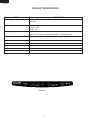
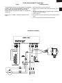
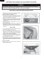
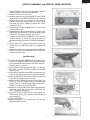
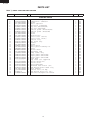
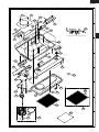
KB-0333KS
KB-0333KK
KB-0333KW
SERVICE MANUAL
S65H253KB033K
INSIGHT RANGE HOOD
MODELS
KB-0333KS
KB-0333KK
KB-0333KW
TABLE OF CONTENTS
Page
PRECAUTIONS TO BE OBSERVED BEFORE BEFORE SERVICING ......................... INSIDE FRONT COVER
WARNING TO SERVICE PERSONNEL .............................................................................................................. 1
FOREWORD AND WARNING ............................................................................................................................. 1
PRODUCT SPECIFICATIONS ............................................................................................................................ 2
WIRE HARNESS DRAWING ............................................................................................................................... 3
COMPONENT REPLACEMENT .......................................................................................................................... 4
PARTS LIST ........................................................................................................................................................ 6
This document has been published to be used for after
sales service only.
The contents are subject to change without notice.
SHARP CORPORATION
1
KB-0333KS
KB-0333KK
KB-0333KW
PRECAUTIONS TO BE OBSERVED BEFORE AND DURING SERVICING TO REDUCE THE RISK OF FIRE,
ELECTRIC SHOCK OR INJURY.
1. Use this unit only in the manner intended by the manufacturer. If you have questions, contact Sharp at
the address or telephone number listed on page 2 of this manual.
2. Before servicing or cleaning unit, switch power off at service panel and lock the service disconnecting means
to prevent power from being switched on accidentally. When the service disconnecting means cannot be locked,
securely fasten a prominent warning device, such as a tag, to the service panel.
3. Installation work and electrical wiring must be done by a qualified person(s) in accordance with all applicable
codes and standards, including fire-rated construction codes and standards.
4. Sufficient air is needed for proper combustion and exhausting of gases through the flue (chimney) of fuel
burning equipment to prevent backdrafting. Follow the heating equipment manufacturer's guideline and safety
standards such as those published by the National Fire Protection Association (NFPA), and the American
Society of Heating, Refrigeration and Air Conditioning Engineers (ASHRAE), and the local code authorities.
5. When cutting or drilling into wall or ceiling, do not damage electrical wiring and other hidden utilities.
6. To reduce the risk of fire or electric shock, do not use this range hood with an additional speed control
device.
7. Ducted fans must always be vented to the outdoors.
8. To reduce the risk of fire, use only metal ductwork.
9. Use with approved cord-connection kit only.
10. This unit must be grounded.
BEFORE SERVICING
Before servicing or cleaning unit, switch power OFF at service panel and lock the service disconnect
to prevent power from being switched on accidentally. When the service disconnecting means cannot
be locked, securely fasten a prominent warning device, such as a tag, to the service panel.
If the Range Hood fails to perform, contact SHARP ELECTRONICS CORPORATION immediately at
1-800-237-4277.
IMPORTANT SAFETY INSTRUCTIONS
TO REDUCE THE RISK OF A RANGE TOP GREASE
FIRE:
1. Never leave surface units unattended at high settings.
Boilovers cause smoking and greasy spillovers that may
ignite. Heat oils slowly on low or medium settings.
2. Always turn hood ON when cooking at high heat or
when cooking flaming foods.
3. Clean ventilating fans frequently. Grease should not
be allowed to accumulate on fan or filter.
4. Use proper pan size. Always use cookware
appropriate for the size of the surface element.
2
1. SMOTHER FLAMES with a close-fitting lid, cookie
sheet or metal tray, then turn off the burner. BE
CAREFUL TO PREVENT BURNS. If the flames do
not go out immediately, EVACUATE AND CALL THE
FIRE DEPARTMENT.
2. NEVER PICK UP A FLAMING PAN — You may be
burned.
3. DO NOT USE WATER, including wet dishcloths or
towels - violent steam explosion will result.
4. Use an extinguisher ONLY if:
A. You know you have a Class ABC extinguisher and
you already know how to operate it.
B. The fire is small and contained in the area where it
started.
C. The fire department is being called.
D. You can fight the fire with your back to an exit.
* Based on “Kitchen Fire Safety Tips” published by
NFPA.
KB-0333KS
KB-0333KK
KB-0333KW
SERVICE MANUAL
PRODUCT DESCRIPTION
INSIGHT RANGE HOOD
KB-0333KS
KB-0333KK
KB-0333KW
COMPONENT REPLACEMENT
FOREWORD
PARTS LIST
This Manual has been prepared to provide Sharp Electronics Corp.
Service Personnel with Operation and Service Information for the
SHARP INSIGHT RANGE HOODS, KB-0333KS, KB-0333KK, KB0333KW.
It is recommended that service personnel carefully study the entire
text of this manual so that they will be qualified to render satisfactory
customer service.
Special attention should be given to avoid electrical shock.
WARNING
1. For general ventilating use only. Do not use to exhaust
hazardous or explosive materials and vapors.
2. To avoid motor bearing damage and noisy and/or unbalanced
impellers, keep drywall spray, construction
dust, etc. off power unit.
3. For best capture of cooking impurities, your range hood should
be mounted so that the top of the hood is 24-30” above the
cooking surface.
4. Please read specification label on product for further
information and requirements.
DANGER
Halogen or incandescent bulbs may be hot! Refer to bulb
packaging for further information.
SHARP ELECTRONICS CORPORATION
SHARP PLAZA, MAHWAH,
NEW JERSEY 07430-2135
1
KB-0333KS
KB-0333KK
KB-0333KW
PRODUCT SPECIFICATION
ITEM
DESCRIPTION
Power Requirements
120 Volts, 60 Amps
60 Hertz
Case Dimensions
Width 30"
Height 7 1/4"
Depth 20"
Hood lamps (3 Levels)
2 bulbs (not included)
40W x 2 (Incandescent light bulbs) or 50W x 2 (Halogen bulbs)
Hood fan (4 Speeds)
Approx. 100 to 430 C.F.M.
Heat Sensor
Advaned Sentry
Delay-off
10 Min delay
Control Complement
DELAY OFF, Fan number pads, ON/OFF, LIGHT Pads, CLEAN FILTER Pad
Safety Standard
UL Listed
Weight
Approx. 29 lbs.
DELAY OFF
1
2
3
4
CLEAN FILTER
ON/OFF
FAN
LIGHT
KB-0333KS
2
FUSE AND SCHEMATIC DIAGRAM
FUSE
KB-0333KS
KB-0333KK
KB-0333KW
To replace the fuse:
The hood control contains a fuse to protect it from power 1. Disconnect power at service entrance.
surges. If the fuse has opened (blown), the green fan2. Remove filters, bottom panel, light wire harness and air
level indicators will operate properly when the fan
chute.
buttons/switches are pressed, but the fan and lights will 3 Remove and inspect fuse. If it is not open (blown), additional
not turn on.
diagnostics need to be done.
4. Install new fuse.
The fuse is a 5 x 20mm, 10 Amp, Fast-Acting, 125V
5. Re-assemble air chute, light wire harness, bottom panel and
(min.).
filters.
6. Turn on power and check hood/control operation.
SCHEMATIC DIAGRAM
3
KB-0333KS
KB-0333KK
KB-0333KW
COMPONENT REPLACEMENT AND ADJUSTMENT PROCEDURE
WARNING :
Before servicing or cleaning unit, switch power OFF at service panel and lock the service disconnect to
prevent power from being switched on accidentally. When the service disconnecting means cannot be locked,
securely fasten a prominent warning device, such as a tag, to the service panel.
LIGHT PANEL and AIR CHUTE REMOVAL/INSTALLATION
1. Switch OFF power at service panel, to prevent accidental
electrical shock, or damage to components.
2. Remove FILTERS and set aside.
3. For models with an inner BOTTOM COVER, remove two
#8 screws (A) attaching BOTTOM COVER (B) to HOOD,
tip BOTTOM COVER down and remove.
4. Remove the two #6 (C) and three #8 (D) pan head
screws attaching the LIGHT PANEL (E) to the HOOD
and lower the LIGHT PANEL to expose the LIGHT
CONNECTOR (F).
5. Disconnect the LIGHT CONNECTOR (F) and set the
LIGHT PANEL aside.
6. Remove the four #8 pan head screws (G) attaching the
AIR CHUTE (H) to the HOOD. Pull forward slightly on the
AIR CHUTE and slide to the right and remove if
neccessary.
INSTALLATION
7. Place the AIR CHUTE (H) into the HOOD and secure in
place with four #8 pan head screws (G).
8. Place the LIGHT PANEL (C) into the HOOD frame. The
front lip of the LIGHT PANEL must be slid behind the
HOOD frame lip. The remaining edges of the LIGHT
PANEL lay over top of the HOOD edges.
9. Secure the LIGHT PANEL to the HOOD using two #6 (C)
and three #8 (D) pan head screws. Reconnect the
LIGHT CONNECTOR plug (F).
10.For models with an inner BOTTOM COVER, set the
BOTTOM COVER (B) in the back edge of the HOOD and
tip up into place and secure with two #8 pan head screws
(A).
11.Install the FILTERS.
12.Switch ON power at the service panel and test the
RANGE HOOD functions.
4
CONTROL ASSEMBLY and CONTROL PANEL SERVICING
1. Switch OFF power at service panel, to prevent accidental
electrical shock, or damage to components.
2. Remove FILTERS and set aside.
3. Remove two #8 screws (A) attaching BOTTOM COVER
(B) to HOOD, tip BOTTOM COVER down and remove.
4. Remove the two #6 (C) and three #8 (D) pan head
screws attaching the LIGHT PANEL (E) to the HOOD
and lower thE LIGHT PANEL to expose the LIGHT
CONNECTOR (F).
5. Disconnect the LIGHT CONNECTOR (F) and set the
LIGHT PANEL aside.
6. Remove the four #8 pan head screws (G) attaching the
AIR CHUTE (H) to the HOOD. Pull forward slightly on the
AIR CHUTE and slide to the right and remove.
7. If replacing the CONTROL ASSEMBLY, use a small flat
blade screwdriver to unlock the connector locks and
disconnect the plugs (I) from the CONTROL ASSEMBLY
(J).
8. Using a utility knife, carefully lift the KEY UNIT (K) and
remove from the CONTROL PANEL (L) to expose the
screws.
9. Remove the three screws (M) attaching the CONTROL
PANEL and CONTROL ASSEMBLY to the HOOD and
remove both from hood.
.
INSTALLATION
10.Position the CONTROL ASSEMBLY (J) into the HOOD,
place the CONTROL PANEL (L) over the assembly and
install the three #6 flat head screws (M). Secure in place.
Do Not overturn the screws.
11.Peel the backing from the new KEY UNIT (K), align the
KEY UNIT with the CONTROL PANEL and carefully
press in place.
12.Align the two CONTROL ASSEMBLY connectors (I) and
plug each into the new connectors until they lock in place.
13.Place the AIR CHUTE (H) into the HOOD and secure in
place with four #8 pan head screws (G).
14.Place the LIGHT PANEL (E) into the HOOD frame. The
front lip of the LIGHT PANEL must be slid behind the
HOOD frame lip. The remaining edges of the LIGHT
PANEL lay over top of the HOOD edges.
15.Secure the LIGHT PANEL to the HOOD using two #6 (C)
and three #8 (D) pan head screws. Reconnect the
LIGHT CONNECTOR plug (F).
16.Set the BOTTOM COVER (B) in the back edge of the
HOOD and tip up into place and secure with two #8 pan
head screws (A).
17.Install the FILTERS.
18.Switch ON power at the service panel and test the
RANGE HOOD functions.
5
KB-0333KS
KB-0333KK
KB-0333KW
KB-0333KS
KB-0333KK
KB-0333KW
PARTS LIST
Note: "§" MARK: PARTS DELIVERY SECTION
REF. NO.
PART NO.
§
DESCRIPTION
Q'TY CODE
ELECTRIC PARTS
1
2
3
4
5
6
6
7
7
8
9
10
11
12
13
14
15
16
17
18
19
20
21
22
23
23
23
24
25
26
27
28
29
30
31
32
33
34
PDUC-B153MRP0
FFTA-B006MRK0
LX-BZB021MRE0
RC-QZB025MRE0
RTRN-B089MRE0
PSHEPB197MRR0
PSHEPB198MRR0
HPNLCB215MRF0
HPNLCB216MRF0
LX-BZB022MRE0
LX-BZB023MRE0
LX-CZB036MRE0
PCOVPB151MRP0
PCOVPB152MRP0
CPNLCB598MRK0
PDUC-B154MRK0
LANG-B034MRP0
LX-BZB024MRE0
LANGTB132MRP0
LX-BZB025MRK0
RMOTEB037MRE0
NFANPB008MRE0
LX-RZB002MRE0
QSOCLB013MRE0
LANG-B037MRP0
LANG-B035MRP0
LANG-B036MRP0
PCOV-B001MRE0
---------PCIL-B001MRE0
FCOVPB049MRK0
RTRN-B090MRE0
PFIL-B015MRE0
FFAN-B018MRK0
FW-VZB293MRE0
QFS-BB007MRE0
A3KBK330
TINSEB430MRK0
M
M
M
M
M
M
M
M
M
M
M
M
M
M
M
M
M
M
M
M
M
M
M
M
M
M
M
M
M
M
M
M
M
M
M
M
M
M
7" Round duct plate
Damper/Duct connector
Screw
Motor capacitor
Isolation transfomer
Key unit (KB-0333KS/KK)
Key unit (KB-0333KW)
Control panel (KB-0333KS/KK)
Control panel (KB-0333KW)
Screw
Screw
Ground screw
Scroll cover (Outlet)
Scroll cover (Front)
Control assy.
Air chute assy.
Baffle
Screw
Motor plate
Motor plate mounting kit
Motor
Blower wheel
Retaining ring
Lamp socket assy
Light panel (KB-0333KS)
Light panel (KB-0333KK)
Light panel (KB-0333KW)
Hole plug
Pop rivet (not supplied)
Filter spring kit
Bottom cover
Autotransformer
Aluminum mesh filter (30")
Non-ducted blower wheel assy
Wire harness
Control fuse (10 amp)
Non-ducted filter kit (30")
Installation/Operation manual
6
1
1
5
1
1
1
1
1
1
1
5
1
1
1
1
1
1
1
1
1
1
1
1
2
1
1
1
1
1
1
1
1
2
1
1
1
1
1
BB
BC
AP
BE
BB
AX
AZ
AZ
BB
AP
AP
AP
BA
BA
BS
BE
AS
AT
BE
AW
BR
BG
AP
BD
BP
BK
BK
AP
AT
BS
BC
BR
BG
BP
AX
BH
AL
KB-0333KS
KB-0333KK
KB-0333KW
2
1
4
3
6
5
HOOD PARTS
1
3
A
A
3
3
4
2
12
3
5
6
B
31
9
B
8
24
Actual wire harness may be different from illustration.
7
10
C
C
28
22
11
D
D
13
22
15
9
E
E
32
14
9
16
23
25
F
17
18
9
F
26
27
19
G
G
29
33
34
20
30
21
H
1
2
H
4
3
7
5
6
KB-0333KS
KB-0333KK
KB-0333KW
NOTES:
8
KB-0333KS
KB-0333KK
KB-0333KW
NOTES:
9
KB-0333KS
KB-0333KK
KB-0333KW
COPYRIGHT © 2005 BY SHARP CORPORATION
ALL RIGHTS RESERVED.
No part of this publication may be reproduced,
stored in retrieval systems, or transmitted in any
form or by any means, electronic, mechanical,
photocopying, recording, or otherwise, without
prior written permission of the publisher.
10