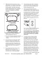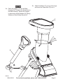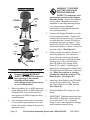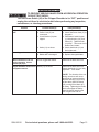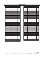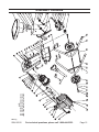
1
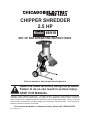
CHIPPER SHREDDER
2.5 HP
Model 66910
Set up and Operating Instructions
Visit our website at: http://www.harborfreight.com
Read this material before using this product.
Failure to do so can result in serious injury.
Save this manual.
Copyright© 2009 by Harbor Freight Tools®. All rights reserved. No portion of this manual or any artwork
contained herein may be reproduced in any shape or form without the express written consent of
Harbor Freight Tools. Diagrams within this manual may not be drawn proportionally. Due to continuing
improvements, actual product may differ slightly from the product described herein. Tools required for
assembly and service may not be included.
For technical questions or replacement parts, please call 1-800-444-3353.
Revised Manual 10h
CAUTION, without the
safety alert symbol, is
used to address practices not
related to personal injury.
Save This Manual
Keep this manual for the safety warnings
and precautions, assembly, operating,
inspection, maintenance and cleaning
procedures. Write the product’s serial number
in the back of the manual (or month and year
of purchase if product has no number). Keep
this manual and the receipt in a safe and dry
place for future reference.
Important Safety
Instructions
In this manual, on the labeling, and
all other information provided with
this product:
When using electric
gardening equipment,
basic safety precautions should
always be followed to reduce the
risk of fire, electric shock, and
personal injury, including the
following:
Read All Instructions
Power Cord Safety
1.
Warning! - To reduce the
risk of electric shock, use
only with an extension cord
intended for outdoor use,
such as an extension cord of cord
type SW-A, SOW-A, STW-A, STOW-A,
SJW-A, SJOW-A, SJTW-A. or
SJTOW-A.
2.
Extension Cord - Make sure your
extension cord is in good condition.
When using an extension cord, be sure
to use one heavy enough to carry the
current your Chipper Shredder will draw.
An undersized extension cord will cause
a drop in line voltage resulting in loss of
power and overheating.
This is the safety alert
symbol. It is used to alert
you to potential personal
injury hazards. Obey all
safety messages that follow
this symbol to avoid possible
injury or death.
DANGER indicates a
hazardous situation
which, if not avoided, will result
in death or serious injury.
WARNING indicates a
hazardous situation
which, if not avoided, could
result in death or serious injury.
CAUTION, used with
the safety alert
symbol, indicates a hazardous
situation which, if not avoided,
could result in minor or moderate
injury.
NOTICE is used to
address practices not
related to personal injury.
Page 2
TABLE A – MINIMUM WIRE GAUGE
FOR EXTENSION CORDS (120 VOLT)
EXTENSION CORD
Ampere
LENGTH
Rating
(at full load) 25’
50’
100’
150’
0–6
18
16
16
14
6 – 10
18
16
14
12
10 – 12
16
16
14
12
12 – 16
14
12
For technical questions, please call 1-800-444-3353.
Not recommended
SKU 66910
3.
Table A shows the correct size to use
depending on cord length and nameplate
ampere rating. If in doubt, use the next
heavier gauge. The smaller the gauge
number, the heavier the cord. To reduce
the risk of disconnection of appliance
cord from the extension cord during
operating:
6.
Use only three-wire outdoor extension
cords that have three-prong grounding
plugs and grounding receptacles that
accept the appliance’s plug.
7.
This Chipper Shredder should be
grounded while in use to reduce the risk
of electric shock to the operator. The unit
is equipped with a 3-conductor cord and
3-prong grounding plug to fit the proper
grounding receptacle. The green or
green and yellow conductor in the cord is
the grounding wire. Do not connect the
green or green and yellow wire to a live
terminal.
Your unit has a plug as illustrated above.
The outlet used should look like the
outlet illustrated above. Do not remove
the grounding prong from the plug. If
the plug will not fit the outlet, have a
proper outlet installed by a qualified
electrician.
a.Make a knot as shown in Method of
Securing Extension Cord; or
b.Use one of the plug-receptacle retaining
straps or connectors described in this
manual.
4.
Ground Fault Circuit Interrupter (GFCI)
protection should be provided on the
circuit(s) or outlet(s) to be used for the
gardening equipment. Receptacles are
available having built-in GFCI protection
and may be used for this measure of
safety.
5.
Do not abuse the Cord - Do not carry
appliance by cord or pull on it to
disconnect from receptacle. Keep the
cord from heat, oil, and sharp edges.
SKU 66910
8.
To reduce the risk of electric shock,
this appliance has a polarized plug
(one blade is wider than the other)
and will require the use of a polarized
extension cord. The power plug will fit
into a polarized extension cord only one
way. If the plug does not fit fully into the
extension cord, reverse the plug. If the
plug still does not fit, obtain a correct
polarized extension cord. A polarized
extension cord will require the use of a
polarized wall outlet. This plug will fit into
the polarized wall outlet only one way.
If the plug does not fit fully into the wall
outlet, reverse the plug. If the plug still
does not fit, contact a qualified electrician
For technical questions, please call 1-800-444-3353.
Page 3
to install the proper wall outlet. Do not
change the equipment plug, extension
cord receptacle, or extension cord plug
in any way. This design is referred to as
double-insulated, indicated by .
9.
WARNING: Handling the cord on this
product will expose you to lead, a
chemical known to the State of California
to cause cancer, and birth defects or
other reproductive harm. Wash hands
after handling. (California Health &
Safety Code § 25249.5, et seq.)
Personal Safety
1.
2.
3.
4.
5.
Dress Properly - Do not wear loose
clothing or jewelry. They can be caught
in moving parts. Use of heavy duty
work gloves and substantial footwear is
recommended when working outdoors.
Wear protective hair covering to contain
long hair.
Wear ANSI-approved safety
goggles and heavy-duty work
gloves. Use face or dust mask
if the operation is dusty.
Avoid unintentional starting - Do not
move plugged-in equipment with your
finger on the power switch. Be sure the
switch is off when plugging in.
Do not overreach - Keep proper footing
and balance at all times.
8.
9.
Wear thick jeans and steeltoed work boots to help
prevent injury caused by
flying debris.
Equipment Use and Care
1.
Avoid a dangerous environment - Do not
use equipment in damp or wet locations.
2.
Do not use in rain.
3.
Keep children away - All visitors should
be kept at a distance from the work area.
4.
When servicing use only identical
replacement parts.
5.
Use the right equipment - Do not use
the equipment for any job except that for
which it is intended.
6.
Do not force the equipment - It will do
the job better and with less likelihood
of injury at the rate for which it was
designed.
7.
Store idle equipment indoors - When
not in use, equipment should be stored
indoors in a clean, dry, safe location out
of reach of children.
8.
Maintain the equipment with care Follow instructions for lubricating and
changing accessories. Inspect the power
cord periodically and, if damaged, have it
repaired by an authorized service facility.
Inspect extension cords periodically and
replace if damaged. Keep handles dry,
clean, and free from oil and grease.
9.
Check for damaged parts - Before using
the equipment, checked to determine
that all guards will operate properly and
perform their intended function. Check
Stay alert - Watch what you are doing.
Use common sense. Do not operate the
equipment when you are tired.
6.
Do not grasp the exposed
cutting blades or cutting
edges when picking up or
holding the equipment.
7.
Keep hands and feet away
from the cutting area.
Page 4
Keephandsawayfromtheblades.
For technical questions, please call 1-800-444-3353.
SKU 66910
for misalignment of moving parts, binding
of moving parts, breakage of parts,
mounting, and any other condition that
may affect its operation. Any part that is
damaged should be properly repaired or
replaced by a qualified technician.
10. Disconnect the equipment - Disconnect
the equipment from the power supply
when not in use, before servicing, when
changing blades and other accessories.
11. Keep all guards in place and in working
order. A guard that is damaged should
be properly repaired or replaced by a
qualified technician.
12. Keep the blades sharp. Using dull
blades will cause excessive wear on the
motor and will cause jamming.
General Safety
1.
Never place your hands or any other
part of your body or clothing inside the
Hopper when the Chipper Shredder is
plugged into an electrical outlet.
2.
Never attempt to cut limbs over 1-1/4”
in diameter. Doing so can cause
equipment damage and/or serious
personal injury.
3.
This Chipper Shredder should only be
operated on a solid, level surface.
4.
Never feed pieces of metal, rocks,
bottles, cans, or other foreign objects
into the Chipper Shredder.
5.
If the cutting mechanism strikes a
foreign object or if the Chipper Shredder
makes an unusual noise or vibration,
immediately turn off the unit. Wait
until the Chipper Shredder comes to a
complete stop. Disconnect the Power
Cord, and take the following steps:
a.Remove any foreign or clogged
material.
SKU 66910
b.Check for any loose parts and tighten.
c. Replace or repair damaged parts.
6.
Periodically stop the Chipper Shredder
and check the discharge area to ensure
the processed material does not build up
and clog the Chute.
7.
Do not move the Chipper Shredder when
the Motor is running or with your finger
on the Power Switch.
8.
Avoid unintentional starting. Prepare to
begin work before turning on the Chipper
Shredder.
9.
Do not leave the Chipper Shredder
unattended when it is plugged into an
electrical outlet. Turn off the unit, and
unplug it from its outlet before leaving.
10. This product is not a toy. Keep it out of
reach of children.
11. People with pacemakers should
consult their physician(s) before use.
Electromagnetic fields in close proximity
to heart pacemaker could cause
pacemaker interference or pacemaker
failure. In addition, people with
pacemakers should:
• Avoid operating alone.
• Do not use with the Power Switch
locked on.
• Properly maintain and inspect to avoid
electrical shock.
12. Maintain labels and nameplates on
the Chipper Shredder. These carry
important safety information. If
unreadable or missing, contact Harbor
Freight Tools for a replacement.
13. The warnings, precautions, and
instructions discussed in this instruction
manual cannot cover all possible
conditions and situations that may occur.
It must be understood by the operator
that common sense and caution are
For technical questions, please call 1-800-444-3353.
Page 5
factors which cannot be built into this
product, but must be supplied by the
operator.
Save these
instructions.
Specifications
Electrical
Requirements
120V~ / 60Hz / 15A
Motor Speed: 3460 RPM
Cutting Capacity 1-1/4” Diameter Maximum
Safety Features
Internal Safety Cut-Off Switch.
(When Knobs (11) are loose or Main
Housing (14) is open Motor will
cease to run.)
Accessories
Feed Stick
5mm Allen Wrench
6mm Allen Wrench
14mm-17mm Wrench
Unpacking
When unpacking, make sure the item
is intact and undamaged. If any parts are
missing or broken, please call Harbor Freight
Tools at 1-800-444-3353 as soon as possible.
Page 6
For technical questions, please call 1-800-444-3353.
SKU 66910
Assembly
Read the entire Important
Safety Instructions section at
the beginning of this manual
including all text under
subheadings therein before set up
or use of this product.
To prevent
serious injury
from accidental
operation:
Turn the Power Switch off and
unplug the power cord before
assembling or making any
adjustments.
Note: For additional information regarding the
parts listed in the following pages, refer
to the Assembly Diagram near the end of
this manual.
Phase 1
Note: Leave Bolts (28, 32) only finger tight
until the end of Phase 2.
Place cupped side of Curved Washers
(27) against Legs (24, 26) during
assembly.
1c. Remove Washers (31, 27) and Bushing
(30) from Bolt (32). Insert Bolt (32)
through Split Washer (83), Washer (31),
Bushing (30), Wheel (29), and Curved
Washer (27), in that order. Thread bolt
into end of rear Axle (25). Snap a Wheel
Cover (33) into place over each hub.
1a. Place Axles (25) into Legs (24, 26).
Note the position of Left and Right
Legs in diagram.
1b. Secure front Axle in place using Curved
Washers (27) and Bolts (28).
33 32
83 31 30 29
C
A
C
A
B
28
B
27
26
25
24
REV 10h
SKU 66910
For technical questions, please call 1-800-444-3353.
Page 7
2c. Insert all four Bolts (64) through the
sides of the motor assembly and the
Leg assembly. Secure with one Curved
Washer (27) and Lock Nut (75) each.
Phase 2
2a. Carefully place motor assembly on floor
with Main Housing (14) facing down.
Main Housing may bend if dropped.
2b. Flip Leg assembly over, and squeeze
legs together to allow them to be inserted
into motor assembly. Line up the holes
at the top of the Legs with the holes on
the motor assembly.
2d. With assistance, turn the assembly back
over. Tighten all Bolts (28, 32, 64) and
Lock Nuts (75), including the ones left
loose from Phase 1.
B
B
75
B
C
27
A
C
B
64
C
14
REV 10h
Page 8
For technical questions, please call 1-800-444-3353.
SKU 66910
Phase 3
3b. Attach the Brace (77) to one of the Legs
and insert the Feed Stick (78) into it.
3a. Place the Hopper (1) onto the Main
Housing (14), lining up the three holes in
the Main Housing. Secure the Hopper
in place using three Washers (8), Spring
Washers (6) and Safety Screws (7).
1
8
6
7
A
78
B
77
REV 10h
SKU 66910
For technical questions, please call 1-800-444-3353.
Page 9
WARNING! To prevent
electric shock and
serious personal
injury: The extension cord
must remain secured to the Chipper
Shredder’s plug. Secure the extension
cord by either using the knot method
explained in the safety warning section,
or by using a device designed
specifically for retaining the extension
cord (sold separately).
Product Features
FIGURE D
CIRCUIT
BREAKER
(39)
POWER
SWITCH
(42)
FEED
STICK
(76)
3.
Position the Chipper Shredder on a flat,
level, dry ground surface. Position the
machine so that the Chute (67) is pointed
in a safe direction, at least 25 feet from
any people, animals, or objects. Then,
chock both Wheels (29) of the machine
with scrap branches or rocks to keep the
unit from rolling. (See Figure E.)
4.
Check to make sure the two Knobs (11)
are firmly tightened. The vibration of
the unit during normal use will cause
the Knobs to loosen and allow the Main
Housing (14) to lift up off the Safety
Shut-Off Switch (55), turning off the
Motor (47) for safety. Tightening the
Knobs firmly will engage the Safety ShutOff Switch and allow the unit to start and
run. While the machine is running,
periodically check the tension of TieDown Knobs. (See Figure E.)
5.
Insert the yellow Safety Lock-Off Switch
into the Power Switch (42). Then turn
the Power Switch to its “ON” position.
(See Figure D.)
6.
Allow the Blades (20) to spin up to full
speed.
7.
IMPORTANT: Branches cannot be more
than 1-1/4” in diameter. Never attempt
to cut limbs over 1-1/4” in diameter.
Doing so can cause equipment damage
and/or serious personal injury.
HOPPER
(1)
MAIN
HOUSING
(14)
TIE-DOWN
KNOBS
(11)
POWER
CORD
(37)
CHUTE
(67)
FIGURE E
Operating Instructions
Read the entire Important
Safety Information section at
the beginning of this manual
including all text under
subheadings therein before set up
or use of this product.
1.
2.
Before operating, put on ANSI-approved
safety glasses under an ANSI-approved
full face shield. Also wear heavy duty
work gloves and NIOSH-approved dust
mask/respirator.
If an extension cord is used, ensure that
it is an outdoor type extension cord and
that it is the correct design to accept this
appliance’s plug.
Page 10
For technical questions, please call 1-800-444-3353.
SKU 66910
8.
9.
Do not force the Chipper Shredder. Let
the natural suction process take in the
material to be cut. Always stand clear
and to the side of the Chute (67).
(See Figure E.)
Without putting your hands into the
Hopper (1), slowly drop the material in
(one branch at a time). The machine will
pull it in automatically. (See Figure E.)
10. WARNING! Never put your hands
into the Hopper (1). Always use the
Feed Stick (76). (See Figure D.)
11. Should the Chipper Shredder jam while
in use, immediately turn the Power
Switch (42) to its “OFF” position.
Unplug the Power Cord (37) from its
extension cord. Unscrew and remove
the two Knobs (11). Open the Main
Housing (14) to expose the two Blades
(20). Clear the jam. Close the Housing,
and retighten the two Tie-Down Knobs.
Then plug the Power Cord into its
extension cord, and turn the Power
Switch to its “ON” position to resume
cutting. (See Figures D and E.)
its extension cord.
(See Figures D and E.)
14. Wait until all moving parts of the Chipper
Shredder have stopped moving. Then
open the machine and clean out the
Hopper (1), Main Housing (14), and
Chute (67). (See Figure E.)
15. Clean, then store the Chipper Shredder
indoors out of reach of children and other
unauthorized persons.
NOTE: Performance will decrease as
the blades wear.
The blades can be reversed to
expose a fresh cutting edge,
see Blade Reversal/Removal on
page 12.
12. NOTE: In extreme working conditions
sensors in the Chipper Shredder will
automatically switch off the Motor (47)
to prevent overheating. In this event,
turn the Power Switch (42) to its “OFF”
position and unplug the machine from
its extension cord. Wait five minutes
or until the Motor has cooled. Clear
the machine of all debris. Depress the
Circuit Breaker (39). Then plug the
machine into its extension cord and turn
the Power Switch to its “ON” position to
resume cutting. (See Figure D.)
13. When finished using the Chipper
Shredder, turn the Power Switch (42) to
its “OFF” position. Remove the Safety
Lock-Off Switch from the Power Switch.
Then unplug the Power Cord (37) from
REV 10h
SKU 66910
For technical questions, please call 1-800-444-3353.
Page 11
Maintenance And
Servicing
Procedures not specifically
explained in this manual must
be performed only by a qualified
technician.
To prevent
serious injury
from accidental operation
or electric shock:
Turn the Power Switch (42) of the
Chipper Shredder to its “OFF”
position and unplug the unit from
its electrical outlet before
performing any inspection,
maintenance, or cleaning
procedures.
4.
WHEN STORING, keep the unit in a
clean, dry, safe location out of reach of
children and other unauthorized persons.
5.
WARNING! If the Power Cord (37)
of this Chipper Shredder is damaged,
the Cord must be replaced only by a
qualified service technician.
To prevent serious injury
from tool failure:
Do not use damaged equipment.
If abnormal noise or vibration
occurs, have the problem
corrected before further use.
1.
2.
3.
BEFORE EACH USE, inspect the
general condition of the Chipper
Shredder. Check for loose screws,
misalignment or binding of moving parts,
cracked or broken parts, damaged
electrical wiring, and any other condition
that may affect its safe operation.
BEFORE AND After EACH Use,
clean out debris inside the Hopper (1),
Main Housing (14), and Chute (67).
Then make sure to tighten the Knobs
(11) firmly.
TO CLEAN THE EXTERIOR PARTS,
use only a clean cloth and mild
detergent. Do not use solvents. Do not
immerse any electrical part of the unit in
liquid.
Blade Reversal/Removal
1.
PERIODICALLY, inspect the two
Blades (20). Using dull Blades will
cause excessive wear on the Motor
(47), and will cause jamming. Reverse
or sharpen the Blades when needed.
Wear heavy-duty work gloves to avoid
accidental cuts to hands and fingers.
To reverse the Blades:
SCREWS
(19)
BLADE
(20)
DISC
(21)
BLADE
(20)
SCREWS
(19)
a.Remove the four Screws (19) that
secure the Blades to the Disc (21).
b.Turn the Blades over to expose the
sharp edges.
c. Then retighten the Screws to secure the
Blades to the Disc.
Call 1-800-444-3353 for replacement
blades.
REV 10h
Page 12
For technical questions, please call 1-800-444-3353.
SKU 66910
TROUBLESHOOTING
To prevent serious injury from accidental operation
or electric shock:
Turn the Power Switch (42) of the Chipper Shredder to its “OFF” position and
unplug the unit from its electrical outlet before performing any inspection,
maintenance, or cleaning procedures.
Problem
Chipper Shredder will not
start.
Possible Cause(s)
1. No power at outlet.
2. Power Cord (37) not
connected.
3. Circuit Breaker (39) has
tripped.
4. Knobs (11) are loose.
Likely Solution(s)
1. Check power at outlet.
2. Check that Power Cord (37) is
plugged in.
3. Clean debris inside Hopper
(1), Main Housing (14), and
Chute (67). Tighten Knobs
(11) firmly*. Then reset circuit
breakers and restart.
4. Check that Knobs (11) are
firmly tightened*.
No cutting action.
1. Unit is clogged with debris.
2. Blades dull or damaged.
1. Clean out all debris from unit.
2. Replace damaged blades.
Motor sounds as if it is not
running properly. Circuit
Breaker (39) trips.
Unit is clogged with debris.
Clean out all debris from unit.
Chipper Shredder shuts off for
no apparent reason.
Knobs (11) are loose.
Clean out all debris from unit.
Check that Knobs (11) are firmly
tightened*. Then restart.
*NOTE: The vibration of the unit
during normal use will cause
the Knobs to loosen and allow
the Main Housing (14) to lift up
off the Safety Shut-Off Switch
(55), turning off the Motor (47)
for safety. Tightening the Knobs
firmly will engage the Safety
Shut-Off Switch and allow the
unit to again start and run.
SKU 66910
For technical questions, please call 1-800-444-3353.
Page 13
PARTS LIST
Part
1
2
3
4
5
6
7
8
9
10
11
13
14
15
16
17
18
19
20
21
22
23
24
25
26
27
28
29
30
31
32
33
34
35
36
37
38
39
40
41
Description
Hopper
Hopper Flap
Press Board
Screw
Lock Nut
Flat Washer
Safety Screw
Washer
Cover
Nut
Tie-Down Knob
Bolt
Main Housing
Bolt
Spring Washer
Fix Board
Washer
Screw
Blade
Disc
Disc Base
End Cap
Right Support Leg
Axle
Left Support Leg
Washer
Screw
Wheel
Bushing
Washer
Screw
Wheel Cover
Washer
Spring Washer
Screw
Power Cord & Plug
Protection Tube
Circuit Breaker
Nut
Wire (A)
Qty.
Part
1
1
1
3
3
3
3
3
2
2
2
2
1
1
1
1
1
4
2
1
1
2
1
2
1
4
2
2
2
2
2
2
3
3
3
1
1
1
1
1
42
43
44
45
46
47
48
49
50
51
52
53
54
55
57
58
59
60
61
62
63
64
65
66
67
68
69
70
71
73
74
75
76
77
78
79
80
82
83
Description
Qty.
Power Switch
Motor Housing
Cable Fix
Capacitor
Covering
Motor Assembly
Washer
Screw
Spring Washer
Washer
Switch Shelf
Wire (B)
Wire (C)
Safety Shut-Off Switch
Cover
Motor Support
Washer
Washer
Screw
Screw
Spring
Screw
Steel Pad
Small Rivet
Chute
Lock Nut
Washer
Safety Screw
Screw
Cupped Washer
Nut
Lock Nut
Feed Stick
Brace
Screw
5mm Allen Wrench
6mm Allen Wrench
14mm-17mm Wrench
Spring Washer
1
1
1
1
1
1
1
2
2
2
1
1
1
1
1
1
1
4
4
4
1
1
4
1
1
4
4
4
4
4
1
4
1
1
1
1
1
1
2
REV 10g
Page 14
For technical questions, please call 1-800-444-3353.
SKU 66910
NOTE:
5mm Allen Wrench (79) not shown.
6mm Allen Wrench (80) not shown.
14mm-17mm Wrench (82) not shown.
ASSEMBLY DIAGRAM
REV 10g
SKU 66910
For technical questions, please call 1-800-444-3353.
Page 15
LIMITED 90 DAY WARRANTY
Harbor Freight Tools Co. makes every effort
to assure that its products meet high quality and
durability standards, and warrants to the original
purchaser that this product is free from defects
in materials and workmanship for the period
of 90 days from the date of purchase. This
warranty does not apply to damage due directly
or indirectly, to misuse, abuse, negligence or
accidents, repairs or alterations outside our
facilities, criminal activity, improper installation,
normal wear and tear, or to lack of maintenance.
We shall in no event be liable for death,
injuries to persons or property, or for incidental,
contingent, special or consequential damages
arising from the use of our product. Some
states do not allow the exclusion or limitation
of incidental or consequential damages, so the
above limitation of exclusion may not apply to
you. This warranty is expressly in lieu
of all other warranties, express or
implied, including the warranties of
merchantability and fitness.
PLEASE READ THE
FOLLOWING CAREFULLY
The manufacturer and/or distributor
has provided the parts list and assembly
diagram in this manual as a reference
tool only. Neither the manufacturer or
distributor makes any representation or
warranty of any kind to the buyer that he
or she is qualified to make any repairs to
the product, or that he or she is qualified
to replace any parts of the product. In
fact, the manufacturer and/or distributor
expressly states that all repairs and
parts replacements should be undertaken
by certified and licensed technicians,
and not by the buyer. The buyer assumes
all risk and liability arising out of his or
her repairs to the original product or
replacement parts thereto, or arising out
of his or her installation of replacement
parts thereto.
Record Product’s Serial Number Here:
Note: If product has no serial number, record
month and year of purchase instead.
To take advantage of this warranty, Note: Some parts are listed and shown for
the product or part must be returned to us
illustration purposes only, and are not
with transportation charges prepaid. Proof
available individually as replacement
of purchase date and an explanation of the
parts.
complaint must accompany the merchandise. If
our inspection verifies the defect, we will either
repair or replace the product at our election or
we may elect to refund the purchase price if we
cannot readily and quickly provide you with a
replacement. We will return repaired products
at our expense, but if we determine there is no
defect, or that the defect resulted from causes
not within the scope of our warranty, then you
must bear the cost of returning the product.
This warranty gives you specific legal rights
and you may also have other rights which vary
from state to state.
3491 Mission Oaks Blvd. • PO Box 6009
Camarillo, CA 93011 • (800) 444-3353
Page 16
For technical questions, please call 1-800-444-3353.
SKU 66910