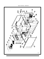
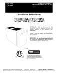
1
OIL FIRED FURNACE
LOW-BOY
Models:
AMT100B34-SM1
AMT100B34-IM2 (AMiT)
AMT200B34-SM3
AMT200B34-IM2 (AMiT)
AMT
AMT-S
DNS-0537 Rev B
C
US
AMiT
AMT-I
INSTALLER / SERVICE TECHNICIAN:
USE THE INFORMATION IN THIS MANUAL FOR THE INSTALLATION AND
SERVICING OF THE FURNACE. KEEP THE DOCUMENT NEAR THE UNIT FOR
FUTURE REFERENCE.
Manufactured by:
Dettson Industries inc.
HOMEOWNER:
PLEASE KEEP THIS MANUAL NEAR THE FURNACE FOR FUTURE
REFERENCE.
Printed in Canada
Printed on 100% recycled paper
Caution : Do not tamper with the
unit or its controls.
Call a qualified service technician.
2011-09-21
3400 Industrial Boulevard
Sherbrooke, Quebec – Canada - J1L 1V8
www.dettson.ca
X40004 Rev. AC
TABLE OF CONTENTS
FIGURES
Figure 1: Fan-limit adjustment and blower regulator ..................8
PART 1 INSTALLATION .................................................3
Figure 2: Model AMT1-1M2 ...........................................................13
1.1) DANGER, WARNING AND CAUTION............................. 3
Figure 3: Model AMT1-SM1...........................................................13
1.2) SAFETY INSTALLATION REQUIREMENTS .................. 3
Figure 4: Model AMT2-IM2 ............................................................14
1.3) GENERAL ........................................................................ 4
Figure 5: Model AMT2-SM3...........................................................14
1.4) POSITIONING THE FURNACE........................................ 4
1.4.1) AIR FOR COMBUSTION AND VENTILATION....... 4
Figure 6: Wiring diagram AMT1-IM2 and AMT2-IM2...................15
Figure 7: Wiring diagram AMT1-SM1 and AMT2-SM3, heating only
........................................................................................16
1.4.2) DUCT RECOMMENDATIONS ................................ 5
Figure 8: Wiring diagram MT1-SM1 and AMT2-SM3, heating and
1.4.3) VENTING INSTRUCTIONS (CHIMNEY
INSTALLATION) .............................................................. 5
1.4.4) VENTING INSTRUCTIONS..................................... 5
optional cooling.............................................................17
Figure 9: Parts list - AMT1-IM2 .....................................................18
Figure 10: Parts list - AMT1-SM1 .................................................20
1.4.5) OIL BURNER .......................................................... 5
Figure 11: Parts list - AMT2-SM3 .................................................22
1.4.6) ELECTRICAL .......................................................... 6
Figure 12: Parts list - AMT2-IM2 ...................................................24
1.4.7) AIR FILTER ............................................................. 6
1.5) BLOCKED VENT SHUT-OFF (BVSO) FOR CHIMNEY
VENTING .......................................................................... 6
TABLES
PART 2 OPERATION ......................................................7
Table 1: Minimum ventilation openings dimensions required in a
2.1) OPERATIONAL CHECKLIST .......................................... 7
closet or enclosure .........................................................4
2.2) COMBUSTION CHECK.................................................... 7
2.3) FAN ADJUSTMENT CHECK ........................................... 7
2.4) LIMIT CONTROL CHECK ................................................ 8
2.4.1) ................FAN-LIMIT ADJUSTMENT AND BLOWER
REGULATOR ................................................................... 8
Table 2: Air filter dimensions for return air duct..........................6
Table 3: Technical specifications for models AMT1/AMT2 (with
3/4 motor) .......................................................................11
Table 4: Technical specifications for model AMT2 (with 1/3 HP
motor) .............................................................................11
PART 3 MAINTENANCE.................................................9
Table 5: Air delivery - CFM with air filter .....................................12
3.1) HEAT EXCHANGER CLEANING .................................... 9
Table 6: Minimum clearances - combustible materials .............12
3.2) BLOWER REMOVAL ....................................................... 9
Table 7: Parts list - AMT1-1M2 .....................................................19
3.3) BLOCKED VENT SHUT OFF (BVSO) CLEANING ......... 9
PART 4 INFORMATION ................................................ 10
Table 8: parts list - AMT1-SM1 .....................................................21
Table 9: Parts list - AMT2-SM3 .....................................................23
Table 10: Parts list - AMT2-IM2 ....................................................25
PART 1 INSTALLATION
FOR YOUR SAFETY
DO NOT STORE OR USE GASOLINE OR OTHER
FLAMMABLE VAPORS AND LIQUIDS IN THE
VICINITY OF THIS OR ANY OTHER APPLIANCE.
DO NOT ATTEMPT TO START THE BURNER WHEN
EXCESS OIL HAS ACCUMULATED, WHEN THE
FURNACE IS FULL OF VAPOUR OR WHEN THE
COMBUSTION CHAMBER IS VERY HOT.
1.1)
DANGER, WARNING AND CAUTION
The words DANGER, WARNING and CAUTION are used to identify the
levels of seriousness of certain hazards. It is important that you
understand their meaning. You will notice these words in the manual as
follows:
DANGER
Immediate hazards which WILL result in death or
serious bodily and/or material damage.
WARNING
Hazards or unsafe practices which CAN result
in death or serious bodily and/or material
damage.
CAUTION
Hazards or unsafe practices which CAN result in
minor bodily and/or material damage.
1.2)
SAFETY INSTALLATION REQUIREMENTS
WARNING
For use with grade 2 fuel oil maximum. Do NOT
use gasoline, crankcase oil or any oil containing
gasoline.
WARNING
Never burn garbage or paper in the heating system
and never leave rags or paper around the unit.
CAUTION
ENVIRONMENTAL HAZARD – Failure to follow
this caution may result in environmental pollution.
Remove and recycle all components or materials
(i.e. oil, electrical and electronic components,
insulation, etc.) before unit final disposal.
CAUTION
These instructions are intended for the sole use of
qualified personnel trained in installing this type of
furnace. Installation of this furnace by an
unqualified person can lead to hazardous
conditions, resulting in bodily harm and/or
equipment damage.
IMPORTANT: For the installation of the sidewall vent of
the Sealed Combustion System, refer to the VTK
Instruction Manual (X40142).
IMPORTANT: All local and national code requirements
governing the installation of oil burning equipment, wiring
and flue connections MUST be followed. Some of the
codes that may be applicable are:
CSA B139
Installation code for oil burning
equipment
NFPA 31
Installation of oil burning equipment
ANSI/NFPA 90B Warm air heating and air conditioning
systems
ANSI/NFPA 211 Chimneys, fireplaces, vents and solid
fuel burning appliances
ANSI/NFPA 70 National electrical code
CSA C22.1
Canadian electrical code
Only the latest issues of the above codes should be
used, and are available from either:
The National Fire Protection Agency
Batterymarch Park
Quincy, MA 02269
or
The Canadian Standards Association
178 Rexdale Blvd.
Rexdale, Ontario
M9W 1R3
3
1.3)
GENERAL
Table 1: Minimum ventilation openings dimensions
required in a closet or enclosure
This furnace is a Low-Boy unit and may be operated in an upflow
configuration only.
It is shipped as a packaged unit, complete with burner and controls. It
requires a line voltage (115 VAC) connection to the control box, a
thermostat hook-up as shown on the wiring diagram, oil line
connection(s), suitable ductwork, and connection to a properly sized
vent.
The air handling capacity of this furnace is also designed for cooling.
Refer to Table 5 for the expected airflow at various external duct static
pressures, based on the model selected.
1.4)
POSITIONING THE FURNACE
The unit must be installed in a location where the ambient and return
air temperatures are above 15°C (60°F).
CAUTION
Input
(BTU/h)
Width
Height
75,000 – 105,000
120,000 – 155,000
0.4 mm (16")
0.5 mm (20")
0.20 mm (8")
0.25 mm (10")
CAUTION
Do not block the combustion air openings in the
furnace. Any blockage will result in improper combustion and may result in a fire hazard and/or
cause bodily harm.
Chimney installation only
This furnace is not watertight and is not designed
for outdoor installation. This furnace shall be
installed in such a manner as to protect the
electrical components from water. Outdoor
installation will lead to hazardous electrical
conditions and to premature furnace failure.
The barometric draft regulator shall be installed in the same room or
enclosure as the furnace, in such a manner as to prevent any
difference in pressure between the regulator and the combustion air
supply.
This furnace is approved for reduced clearances to combustible
construction; therefore, it may be installed in a closet or similar
enclosure. This unit may be located in a basement or on the same
level as the area to be heated. Whichever the case, the unit must
always be installed level.
In unconfined spaces, in buildings of conventional frame, brick or stone
construction, infiltration may be adequate to provide air for combustion,
ventilation and dilution of flue gases. This determination must be made
on an individual installation basis and must take into consideration the
overall volume of the unconfined space, the number of windows and
ventilation openings, the number of doors to the outside, internal doors
which can close off the unconfined space and the overall tightness of
the building construction.
In a basement, or when installed on the floor, as in a crawlspace, it is
recommended that the unit be installed on a concrete pad that is 2.54
to 5.08 cm (1 to 2") thick.
The required minimum clearances for this furnace are specified in
Table 6
The furnace should be positioned as closely as possible to the
chimney or vent in order to keep vent connections short and direct. It
should also be as close as possible to the centre of the air distribution
system.
1.4.1)
Air for combustion and ventilation
Refer to the CAN/CSA-B139 installation code for complete regulations,
and for guidance on retrofit applications.
This furnace must be installed in a location that provides sufficient air
for proper combustion, appropriate venting and the maintenance of an
ambient temperature at safe limits under normal conditions of use. The
location should not interfere with proper circulation of air within the
confined space.
When this furnace is installed in a closet or enclosure, 2 ventilation
openings are required for combustion air. The openings should be
located about 15.24 cm (6") from the top and the bottom of the
enclosure at the front of the furnace. Table 1 indicates the minimum
ventilation opening dimensions required.
4
Air requirements for the operation of exhaust fans, kitchen ventilation
systems, clothes dryers, and fireplaces shall be considered in
determining the adequacy of the space to provide the required
combustion air.
Many new buildings and homes (even older ones that have been
weatherized) must be considered as being of tight construction and,
therefore, infiltration will not be sufficient to supply the necessary air for
combustion and ventilation.
A building can be considered as being of tight construction when:
a.
Walls and ceilings exposed to the outside have a continuous
water vapour retarder with a rating of one perm or less, with
openings hermetically sealed and/or;
b.
Weather-stripping has been added on operable windows and
doors, and/or;
c.
Caulking or sealant have been applied to areas such as joints
around window and door frames, between sole plates and floors,
between wall-ceiling joints, between wall panels, at penetrations
for plumbing, electrical and fuel lines and at other openings.
If combustion and ventilation air must be supplied to an unconfined
space from the outside, an opening with a free area of not less than
2
2
6.45 cm (one inch ) per 1,000 BTU per hour of total input of all
2
appliances within the unconfined space, but not less than 645.16 cm
2
(100 inches ) must be provided. This opening must be located such a
way that it cannot be blocked in any way, at any time.
1.4.2)
Duct recommendations
The proper sizing of warm air ducts is necessary to ensure
satisfactory furnace operation. Ductwork should be in accordance
with the latest editions of ANSI / NFPA-90A (Installation of Air
Conditioning and Ventilating Systems) and NFPA-90B (Warm Air
Heating and Air Conditioning Systems) or Canadian equivalent.
The supply air ductwork should be attached to the flanged front
opening provided at the discharge end of the furnace and the return
air ductwork should be attached to the flanged rear opening of the
furnace. See Figures 2, 3, 4 and 5, for the dimensions of these
openings, based on the model selected.
The following recommendations should be followed when installing
ductwork:
a.
Install locking type dampers in all branches of the individual
ducts to balance out the system. Dampers should be adjusted
to achieve the desired static pressure at the outlet of the
furnace;
b.
A flexible duct connector of non-combustible material should be
installed on both the supply and return air sections of the unit.
On applications where an extremely quiet operation is
necessary, the first 3 m (10') of supply and return ducts should
be internally lined with acoustical material, if possible;
c.
In cases where the return air grille is located close to the fan
o
inlet, there should be at least one 90 air turn between the fan
inlet and grille. Further reduction in noise levels can be
achieved by installing acoustical air turning vanes or by lining
the duct as described in b. above;
d.
When a single air grille is used, the duct between the grille and
the furnace must be the same size as the return opening in the
furnace.
WARNING
Return air grilles and warm air registers must not
be obstructed.
This inspection should include the following:
a.
Inspection for any deterioration in the chimney or vent. If
deterioration is discovered, the chimney must be repaired or
the vent must be replaced;
b.
Inspection to ascertain that the vent system is clear and free of
obstructions. Any blockages must be removed before installing
this furnace;
c.
Cleaning the chimney or vent if previously used for venting a
solid fuel burning appliance or fireplace;
d.
Confirming that all unused chimney or vent connections are
properly sealed;
e.
Verification that the chimney is properly lined and sized per the
applicable codes (refer to list of codes in section 1.2).
Masonry Chimney
This furnace can be vented into an existing masonry chimney.
However, it must not be vented into a chimney servicing a solid fuel
burning appliance. Before venting this furnace into a chimney, the
chimney must be checked for deterioration and repaired if
necessary. The chimney must be properly lined and sized per local
or national codes.
If the furnace is vented into a common chimney, the chimney must
be of sufficient area to accommodate the total flue products of all
appliances vented into the chimney.
Following are the preconditions for a safe venting system:
a.
Ensure that the chimney flue is clear of any dirt or debris;
b.
Ensure that the chimney is not servicing an open fireplace;
c.
Never reduce the pipe size below the outlet size of the furnace;
d.
All pipes should be supported using the proper clamps and/or
straps. These supports should be at least every 1.2 m (4');
e.
All horizontal runs of pipe should have an upward slope of at
least 2 cm per 1 m (1/4" per 1');
f.
All runs of pipe should be as short as possible with as few turns
as possible;
CAUTION
g.
Seams should be tightly joined and checked for leaks;
When ducting supplies air to a space other than
where the furnace is located, the return air ducts
must be sealed and also be directed to the space
other than where the furnace is located. Incorrect
ductwork termination and sealing will create a
hazardous condition that can lead to bodily harm.
h.
The flue pipe must not extend into the chimney but be flush
with the inside wall;
i.
The chimney must extend 0.9 m (3') above the highest point
where it passes through a roof of a building and at least 0.6 m
(2') higher than any portion of a building within a horizontal
distance of 3 m (10'). It shall also be extended at lest 1.5 m (5')
above the highest connected equipment flue collar;
j.
Check local codes for any variances.
1.4.3)
Factory Built Chimneys
Venting instructions (chimney installation)
The furnace must be vented to the outside, in accordance with local
codes and other authorities having jurisdiction.
CAUTION
Oil fired appliances must be connected to flues
having sufficient draft at all times to ensure safe
and proper combustion.
For additional venting information refer to ANSI / NFPA 211
Chimneys, Fireplaces, Vents and Solid Fuel Burning Appliances
and/or CSA B139 Installation Code.
This furnace is certified for use with a Type “L” vent.
Pre-installation inspection of vent system
The furnace may be used with an approved factory built chimney.
Refer to chimney manufacturer’s instructions for proper installation.
1.4.4)
Venting instructions
(Sealed Combustion System)
Refer to the sealed combustion system (VTK) Instruction Manual
(X40142).
1.4.5)
Oil burner
This furnace is supplied with a high pressure atomizing retention
head type burner (for use with not heavier than grade 2 fuel oil). If
the burner model is a Beckett AFG, the mounting flange is fixed to
the burner air tube and no adjustment is required for insertion
length. If a Riello burner is used, refer to the Technical
Specifications, Table 3 for the insertion length.
Before installing this furnace, it is highly recommended that any
existing vent system be completely inspected.
5
CAUTION
NEVER use the “interrupted ignition” function if a
Honeywell R7184 series combustion relay is
installed on the burner.
Oil Connections
Complete instructions for the installation of the fuel oil piping can be
found in the oil burner installation instructions included with the
furnace.
When installing optional accessories on this appliance, follow the
manufacturer’s installation instructions included with the accessory.
Other than wiring for the thermostat, wire with a minimum of type “T”
o
o
insulation (17 C rise (63 F)) must be used for accessories.
1.4.7)
Air filter
An internal filter rack, located in the blower compartment, is provided
as standard equipment with this furnace. A sufficient clearance
should be provided for air filter access. Refer to Table 2 for filter rack
flange dimensions for the return air duct.
On models with a vestibule, 2 oil line entry holes are provided in the
side panels, so that a two-pipe system may be used, if desired.
DANGER
A 10 (or finer) micron oil filter should be used with all oil burners and
installed as closely as possible to the burner.
Do not use this furnace as a construction heater.
Use of this furnace as a construction heater
exposes it to abnormal conditions, contaminated
combustion air and the lack of air filters. Failure to
follow this warning can lead to premature furnace
failure and/or vent failure that could result in a fire
hazard and/or bodily harm.
Barometric Draft Control
A barometric draft control must be used with the furnace in chimney
venting to ensure proper operation. Installation instructions are
enclosed with the control.
1.4.6)
Electrical
The appliance must be installed in accordance with the current
ANSI / NFPA 70 National Electrical Code / CSA C22.1 Canadian
Electrical Code Part 1 and/or local codes.
The control system depends on the correct polarity of the power
supply. Connect “HOT” wire (H) and “NEUTRAL” wire (N) as shown
in Figures 6, 7 and 8, based on the model selected.
A separate line voltage supply should be used with fused disconnect
switch or circuit breaker between the main power panel and the unit.
CAUTION
1.5)
Blocked vent shut-off (BVSO)
For chimney venting
WARNING
It is imperative that this device be installed by a
qualified agency.
This device is designed to detect the insufficient evacuation of
combustion gases in the event of a vent blockage. In such a case
the thermal switch will shut down the oil burner. The device will then
need to be re-armed MANUALLY.
The furnace cabinet must have an uninterrupted
or unbroken electrical ground to minimize
personal injury if an electrical fault should occur.
A green ground screw is provided in the control
box for this connection.
Refer to the wiring diagrams and the detailed instructions supplied
with the BVSO for the installation and wiring procedures. The length
of wires supplied with the unit is such that the safety device must be
installed between the flue outlet of the appliance and the draft
regulator, as indicated in the instructions.
Use only copper wire for 115V power supply to the unit.
It is also essential that the BVSO be maintained annually. For more
details refer to the instructions supplied with the device itself, as well
as Section 3 of this Manual.
Metallic conduit (where required/used) may terminate at the side
panel of the unit. It is not necessary to extend the conduit inside the
unit from the side panel to the control box.
o
When replacing any original furnace wiring, use only 105 C,
16 AWG copper wire.
Instructions for wiring the thermostat are enclosed in the thermostat
carton (field supplied). Make the thermostat connections as shown
in Figures 6, 7 and 8, based on the selected model at the 24 Volt
terminal board on the primary relay.
CAUTION
A positive pressure venting system (Sealed
Combustion System or Direct Vent) MUST NOT
use the BVSO. Follow the instructions supplied
with the venting system.
Table 2: Air filter dimensions for return air duct
6
Furnace
Model
Air Filter
Quantity and Size
Supply Opening Size
Return Opening Size
AMT1-IM2, AMT1-SM1
(2) 12" x 20"
0.5 m x 0.5 m (20" x 20")
0.5 m x 0.5 m (20" x 20")
AMT2-IM2, AMT2-SM3
(2) 16" x 20"
0.6 m x 0.5 m (24" x 20")
0.55 m x 0.5 m (22" x 20")
PART 2 OPERATION
2.1)
OPERATIONAL CHECKLIST
5.
1=> Is the electrical wiring completed according to
Figures 6, 7 and 8?
2=> Is the blower access door secured in place?
The CO2 and flue temperature instruments will enable you to
obtain the data that are required to determine the terminal
efficiency of the furnace. Although this information is good to
have, it is not essential in the basic set up of the furnace. The
proper procedure for performing this operation is as follows:
a.
3=> Is the valve on the oil line open?
4=> Is the “RESET BUTTON’’ on the primary control
pushed down?
5=> Are the flame observation door and the two cleanout
access doors located at the front of the unit closed?
6=> Is the room thermostat in the heating mode and set
above room temperature?
7=> If yes, put the main electrical switch to the “ON’’
position and the burner should start.
2.2)
2.
The overfire draft, which is taken through the observation door
(located in the center line above the burner in the front panel of
the furnace), is a measurement that is necessary to determine
if there is a blockage in the heat exchanger or the flue pipe.
Refer to the Technical Specifications in this manual for overfire
pressure values. A high pressure condition may be caused by
excessive combustion air due to the air band being too wide
open or a lack of flue draft (chimney effect) or some other
blockage, such as soot, in the secondary section of the heat
exchanger or the use of an oversize nozzle input or high
pressure pump;
The new reading should now be ZERO smoke;
The proper procedure for performing this operation is as
follows:
For chimney installation only: in order to ensure the proper
draft through the furnace, a barometric draft regulator must be
installed as closely to the breach of the furnace as possible. In
order for this device to function properly, the barometric
damper must be mounted with the hinge pin horizontal and the
face of the damper vertical (see instructions included with
damper). The draft regulator should be adjusted after the
furnace has been firing for at least five minutes and set
between -.025" W.C. and -.035" W.C.;
4.
d.
On a new installation, the air entrapped in the oil line leading
from the tank to the nozzle must be thoroughly purged in order
to prevent excessive after drip. The oil pump is provided with a
special fitting that will enable you to purge any air between the
tank and oil pump;
Using a test kit, measure the smoke level and adjust it to a
“trace” level (between 0 and 1). It is recommended to use a
Bacharach true spot smoke test set or equivalent;
For flue pipe pressure on sidewall installations (VTK), refer to
the technical specifications, Table 3, in this manual;
Open the burner air shutter to get 1.5% CO2 less than the
previous reading and take a smoke test in this condition;
7.
COMBUSTION CHECK
3.
Take a CO2 reading and write it down;
c.
A 10 micron (or finer) oil filter should be installed as closely to
the burner as possible, on all oil burners, but it is particularly
essential on lower firing rate burners. We recommend the use
of a low pressure drop oil filter with a greater capacity than the
fuel pump;
In order to obtain optimum performance from the oil burner, the
following set-up procedures must be followed (refer to the technical
specifications, Table 3, in this manual):
1.
b.
6.
CAUTION
Do not tamper with the unit or its controls. Call a
qualified service technician.
Start the appliance and from the test port near the
BREACH PLATE (VTK) location or on the flue pipe just
before the draft regulator (chimney), proceed with smoke
test and adjust the burner to get between a trace to a #1
smoke rating after a minimum of 5 minutes of operation;
a.
Place a piece of 6 mm (1/4”) diameter clear plastic tubing
over the purge fitting on the oil pump;
b.
Start the oil burner, then open the purge fitting and allow
the burner to run until the purge tube is completely free of
air bubbles;
c.
At this point tighten the purge fitting, which will allow the
oil to run to the nozzle and fire the burner. If the purging
takes longer than 15 seconds and no flame has been
established the burner will stop. Push the reset button on
top of the Primary Control to restart burner.
For detailed information on the operation of the Primary Control
refer to the instructions included with the furnace or burner.
8.
2.3)
After all the set-up procedures mentioned above are
completed, the burner should be fired and an inspection mirror
should be used to observe the flame pattern at the tip of the
nozzle. Any irregularities such as burning to one side or
pulsating flame patterns should be corrected by changing the
nozzle.
FAN ADJUSTMENT CHECK
This furnace is equipped with a 4 speed direct drive motor to deliver
a temperature rise within the range specified on the rating plate.
Adjust the fan speed ACCORDING TO THE OIL INPUT
SELECTED, so that the temperature rise is within the range
specified on the rating plate (see Table 3). Consult the wiring
diagram for speed changes on the direct drive motor.
The blower start / stop is controlled by a helical bi-metal Fan-Limit
Control, which is adjusted to start at 43°C (110°F) and stop at 32°C
(90°F). These are factory set limits which must not be changed or
tampered with.
7
2.4)
LIMIT CONTROL CHECK
The Limit Control is factory adjusted according to Figure 1.. After the
furnace has been in operation for at least 15 minutes, restrict the
return air supply by blocking the filters or closing the return registers
and allow the furnace to shut down on high limit. The burner will shut
OFF and the main blower should continue to run.
Figure 1: Fan-limit adjustment and blower regulator
Remove the restriction and the burner should come back on in a few
minutes.
For Year Round Air Conditioning
The furnace is designed for use in conjunction with cooling
equipment to provide year round air conditioning. The blower has
been sized for both heating and cooling; however, the fan motor
speed may need to be changed to obtain the necessary cooling
airflow.
Heating
The blower speed is factory set to deliver the required airflow at
normal duct static pressure.
Cooling
The blower speed may be adjusted in the field to deliver the required
airflow for cooling, as outlined in Table 5, according to the selected
model.
Constant Blower Switch
This furnace is equipped with a constant low speed blower option.
Whenever the room thermostat is not calling for heating or cooling,
the blower will run on low speed in order to provide air circulation. If
this constant blower option is not desired, the rocker switch on the
side of the control box can be used to “turn off” this feature.
2.4.1)
Fan-Limit adjustment and blower regulator
Modification of the “FAN ON” and “HI” limit settings on the Fan-Limit
can cause malfunctioning of the furnace and result in premature
wear of the heat exchanger.
CAUTION
Modification of the factory set limits will void the
warranty.
8
DNS-0355 Rev A
1 Limit “FAN OFF”
2 Limit “FAN ON”
3 Limit “HI”
Model: AMT1-SM1 & AMT1-IM2
Model: AMT2-IM2
Model: AMT2-SM3
90°F
110°F
170°F
190°F
180°F
PART 3 MAINTENANCE
This furnace should never be operated without an air filter.
Disposable filters should be replaced at least once a year. If
equipped to provide cooling, filters should be replaced a minimum of
twice a year.
3.2)
To avoid personal injury, make sure the power is “OFF” before
servicing.
2.
Remove blower access door;
3.
Remove the 4 blower retaining wing-nuts;
ALWAYS KEEP THE OIL VALVE CLOSED IF THE BURNER IS
SHUT DOWN FOR AN EXTENDED PERIOD OF TIME.
To remove the blower from the furnace:
1.
For optimum performance, the oil burner nozzle should be replaced
at least once a year.
The procedure for the installation and/or replacement of a nozzle is
outlined in the oil burner instruction manual which is supplied with
the furnace.
After replacing the nozzle, the burner should be adjusted in
accordance with the “COMBUSTION CHECK” section of this
manual.
3.1)
HEAT EXCHANGER CLEANING
Normally, it is not necessary to clean the heat exchanger or flue pipe
every year, but it is advisable to have a qualified service technician
check the unit before each heating season to determine whether
cleaning or replacement of parts is required.
If cleaning is necessary, the following steps should be followed:
1.
Turn “OFF” all power upstream from the furnace;
2.
Disconnect the flue pipe and breach plate. On sealed
combustion systems do not disconnect the flue pipe, remove
the breach plate only;
3.
Remove the radiator baffle;
4.
Disconnect the oil line and remove the oil burner from the
furnace;
5.
Clean the secondary tubes and the primary cylinder with a stiff
brush and remove debris with a vacuum cleaner;
6.
Before reassembling the furnace, the heat exchanger and
combustion chamber should be inspected to determine if
replacement is required;
7.
After cleaning, replace the radiator baffle, flue collar plate and
oil burner;
8.
Readjust burner for proper operation.
Turn “OFF” all power upstream from the furnace;
4.
Slide the blower on the rails toward the rear of the unit;
5.
Reverse the above steps to reinstall the blower. (Refer to wiring
diagram Figures 6, 7 and 8 of this instruction manual or the
diagram located on the inside of the blower door to properly
rewire the unit.
WARNING
Be sure to turn all power “OFF” upstream from
the unit when servicing the furnace, unless power
is required for specific operations. Failure to
comply with this CAUTION can result in bodily
harm and/or cause a fire hazard.
BLOWER REMOVAL
3.3)
BLOCKED VENT SHUT OFF (BVSO)
CLEANING
For continued safe operation, the Blocked Vent Shut-Off System
(BVSO) needs to be inspected and maintained annually by a
qualified service technician.
1.
Disconnect the power to the appliance;
2.
Remove the two screws holding down the BVSO assembly
cover;
3.
Remove the cover;
4.
Remove the two screws holding the control box to the heat
transfer tube assembly. Sliding the control box in the appropriate
direction will unlock it form the heat transfer tube assembly;
5.
Carefully remove any build-up from the thermal switch surface;
CAUTION
Do not dent or scratch the surface of the thermal
switch. If the thermal switch is damaged, it must
be replaced.
6.
Clear and remove any build-up or obstruction inside the heat
transfer tube;
7.
Re-mount, lock and fasten the control box with the 2 screws
removed in step 4;
8.
Re-attach the assembly cover with the screws removed in step 2;
9.
Re-establish power to the appliance.
9
PART 4 INFORMATION
Model:
Serial number:
Furnace installation date:
Service telephone # - Day:
Night:
Dealer name and address:
START-UP TEST RESULTS
Nozzle:
Pressure:
Burner adjustments:
lb/psi
Primary air
Fine air
Drawer Assembly
CO2 :
%
Smoke scale:
(Bacharach)
Gross flue temperature:
°F
Ambient temperature:
°F
Chimney draft:
" W.C."
Overfire draft:
" W.C."
Test performed by:
10
Table 3: Technical specifications for models AMT1/AMT2 (with 3/4 motor)
Models: AMT1 and AMT2
75
90
105
120
140
155
RATING AND PERFORMANCE
Firing rate (USGPH)
Input (BTU/h)
Heating capacity (BTU/h)
Heating temperature rise
Flue draft minimum (W.C.) (chimney)
Overfire pressure (W.C.) (chimney)
Flue draft minimum (W.C.) (direct vent)
Overfire pressure (W.C.) (direct vent)
BECKETT BURNER; MODEL AFG (3450 rpm )
0.50
70 000
57 000
0.65
0.75
91 000
105 000
74 000
85 000
13 - 29°C (55 - 85°F)
(-0.06" to -0.025")
(+0.010" to 0.025")
AFG-F3 (tube insertion 2 7/8")
0.85
119 000
97 000
1.00
1,10
140 000
154 000
115 000
126 000
13 - 29°C (55 - 85°F)
(-0.06" to -0.025")
(max +0.025")
(+0.10" to +0.25")
(+0.12" to +0.27")
AFG-F3 (ins. 2 7/8")
AFG-F6(2 7/8")
Low firing rate baffle
APPLICABLE
3 3/8" # 31646
Static disc, model
Nozzle (Delavan)
0.50 - 70W
0.55 - 70B
0.65 - 70B
Pump pressure (PSIG)
100
140
130
Combustion air adjustment (band/shutter)
0/5
0/7
0/8
82,4%
80,9%
81,1%
AFUE % (From CSA B212 standard and Canadian r
APPLICABLE
2 3/4" # 3383
0.75 - 70B
0.85 - 70B
130
140
1/8
4/4
81.4%
80.3%
APPLICABLE
2 3/4" # 3383
0.85 - 70B
170
2/8
80.1%
RIELLO BURNER 40-F (Chim ney vent)
F5 (tube insertion 3 9/16")
0.75 - 70B 0.85 - 70W
1.00 - 70W
130
140
125
0/3
0 / 3.5
0/4
84.7%
83.9%
83.1%
F3 (tube insertion 3 9/16")
Nozzle (Delavan)
0.40 - 70A 0.50 - 70W 0.65 - 70W
Pump pressure (PSIG)
155
170
135
Combustion air adjustment (turbulator/damper)
0/3
0 / 3.5
0/4
AFUE % (From CSA B212 standard and Canadian r
84,4%
82,9%
83,1%
RIELLO BURNER 40-BF (Direct vent)
Nozzle (Delavan)
Pump pressure (PSIG)
0.75 - 70B
Combustion air adjustment (turbulator/damper)
AFUE % (From CSA B212 standard and Canadian regulation)
BF5 (tube insertion 2 3/4")
0.85 - 70W
1.00 - 70W
130
140
125
0 / 3.75
84.7%
1/4
83.9%
1.5/5
83.1%
ELECTRICAL SYSTEM
Volts - Hertz - Phase
115 - 60 - 1
115 - 60 - 1
104 - 132
104 - 132
Rated current (Amps)
12.2
15.7
Minimum ampacity for w iring sizing
13.7
18.1
Max. w ire lenght
26'
26'
Max. fuse size (Amps)
15
20
40 VA
40 VA
Heating
40 VA
40 VA
Cooling
30 VA
30 VA
Operating voltage range
Control transformer
External control pow er available
BLOWER DATA
Blow er speed at 0.50" W.C. static pressure
Blow er speed at 0.25" W.C. static pressure
Motor HP / Speeds
Blow er w heel size
MED-LOW
MED-LOW
MED-HIGH
MED-HIGH
1/3 - 4
HIGH
HIGH
MED-LOW
LOW
MED-HIGH
MED-LOW
3/4 - 4
HIGH
MED-HIGH
10" x 8"
12" x 10"
21¼" x 55" x 32"
20" x 20"
20" x 20"
(2) 12" x 20"
86 kg (190 lbs)
3 tons
21¼" x 61½" x 35¼"
24" x 20"
20" x 22"
(2) 16" x 20"
97 kg (215 lbs)
5 tons
GENERAL INFORMATION
Overall dimensions (w idth x depth x height)
Supply air opening
Return air opening
Filter quantity and size
Shipping w eight
Air conditioning, maximum output
Table 4: Technical specifications for model AMT2 (with 1/3 HP motor)
Models: AMT1 and AMT2
RATING AND PERFORMANCE
ELECTRICAL SYSTEM
120
140
155
MED-LOW
LOW
MED-HIGH
MED-LOW
1/3 - 4
HIGH
MED-HIGH
(SEE TABLE 3)
(SEE TABLE 4 WITH 1/3 HP MOTOR)
BLOWER DATA
Blow er speed at 0.50" W.C. static pressure
Blow er speed at 0.25" W.C. static pressure
Motor HP / Speeds
Blow er w heel size
10" x 10"
11
Table 5: Air delivery - CFM with air filter
AMT75 to AMT105 (1/3 HP MOTOR)
SPEED
EXTERNAL STATIC PRESSURE WITH AIR FILTER
0.2" (W.C.)
1425
1130
840
725
HIGH
MED-HIGH
MED-LOW
LOW
0.3" (W.C.)
1350
1045
810
730
0.4" (W.C.)
1305
1000
770
740
0.5" (W.C.)
1250
950
740
745
AMT120 to AMT155 (3/4 HP MOTOR)
SPEED
EXTERNAL STATIC PRESSURE WITH AIR FILTER
0.2" (W.C.)
0.3" (W.C.)
2080
1892
1556
1221
HIGH
MED-HIGH
MED-LOW
LOW
0.4" (W.C.)
2041
1965
1859
1770
1475
1394
1164
1081
AMT120 to AMT155 (1/3 HP MOTOR)
SPEED
0.5" (W.C.)
1864
1675
1318
998
EXTERNAL STATIC PRESSURE WITH AIR FILTER
0.2" (W.C.)
1650
1450
1215
850
HIGH
MED-HIGH
MED-LOW
LOW
0.3" (W.C.)
1600
1360
1180
845
0.4" (W.C.)
1560
1305
1130
840
0.5" (W.C.)
1510
1250
1100
840
Table 6: Minimum clearances - combustible materials
CLEARANCES
(combustible
materials)
RECOMMENDED
ACCESS FOR SERVICE
FURNACE
2.54 cm (1")
0.6 m (24")
SUPPLY PLENUM WITHIN 1.8 M (6') OF FURNACE
2.54 cm (1")
ACCESS PANEL TO BLOWER
10.16 cm (4")
FURNACE OR PLENUM
50.8 mm (2")
HORIZONTAL WARM AIR DUCT WITHIN 1.8 m (6') OF FURNACE
50.8 mm (2")
LOCATION
SIDES
BACK
TOP
BOTTOM
FLUE PIPE
FRONT
12
APPLICATION
FURNACE (COMBUSTIBLE FLOOR)
0.6 m (24")
0"
HORIZONTALLY OR BELOW FLUE PIPE
10.16 cm (4")
VERTICALLY ABOVE FLUE PIPE
22.86 cm (9")
FURNACE
20.32 cm (8")
0.6 m (24")
Figure 2: Model AMT1-IM2
Figure 3: Model AMT1-SM1
13
Figure 4: Model AMT2-IM2
Figure 5: Model AMT2-SM3
14
Figure 6: Wiring diagram AMT1-IM2 and AMT2-IM2
15
Figure 7: Wiring diagram AMT1-SM1 and AMT2-SM3, heating only
16
Figure 8: Wiring diagram MT1-SM1 and AMT2-SM3, heating and optional cooling
17
Figure 9: Parts list - AMT1-IM2
B50054B
18
Table 7: Parts list - AMT1-IM2
ITEM
1
2
3
4
5
6
7
8
9A
9B
10
11
12
13
14
15
16
17
18
19
20
21
22
23
24
25A
25B
25C
25D
26
27
28
29
30
31
32
33
34
35
36
37
38
39
40
41
42
43
44
45
46
47
48
49
50
51A
51B
52
DESCCRIPTION
HEAT EXCHANGER ASSEMBLY
FLOOR BAFFLE
BOTTOM DIVIDER ASSEMBLY
DD BLOWER SUPPORT
BAFFLE
PANEL ASSEMBLY, LEFT SIDE
INSULATION, LEFT SIDE PANEL
FILTER SUPPORT
SMOKE BOX
COVER ASSEMBLY, SMOKE OUTLET
FLOOR ASSEMBLY
INSULATION
BAFFLE ASSEMBLY
PANEL ASSEMBLY, TOP REAR
DOOR ASSEMBLY, REAR
DIVIDER, TOP
FILTER SUPPORT
PANEL ASSEMBLY, RIGHT SIDE
INSULATION, RIGHT SIDE PANEL
FRONT PANEL ASSEMBLY
INSULATION, FRONT PANEL ASSEMBLY
TOP PANEL, ELECTRICAL COMPARTMENT
BURNER COMPARTMENT, RIGHT SIDE
ELECTRICAL PANEL
ELECTRICAL PANEL, INTERIOR
ACCESS DOOR ASSEMBLY
INSULATION, ACCESS DOOR
INSULATION, ACCESS DOOR SIDE
INSULATION, ACCESS DOOR SIDE
CORNER CONDUIT
BURNER COMPARTMENT, LEFT SIDE
FAN LIMIT, 11-1/2"
MOTOR ASSEMBLY 1/3 HP
BLOWER ASSEMBLY, REPLACEMENT
BLOWER, 100-8R DD
OBSERVATION DOOR ASSEMBLY
CAPACITOR, 5 MF
PAPER FILTER, 12" x 20" x 1"
FLANGE NUT, HEXAGONAL 3/8-16NC BRASS
GASKET, SMOKE PIPE COVER
THERMODISC PLATE
ROCKER SWITCH, SPST
THUMBSCREW KIT ASSEMBLY
SINGLE TERMINAL STRIP, 6 BUSS
TRANSFORMER, 120-24VAC
RELAY, SPDT 24 VAC
SCREW TERMINAL STRIP, 6-POSITION
CAPACITOR SUPPORT
GASKET, PEEP HOLE
HANDLE, RECESSED, BLACK
BUSS RETAINING CLIP
SEAL STRIP, 1/4" x 1/8" x 25'
ELECTRICAL KIT, BVSO EXT.
BLOCKED VENT SHUT-OFF BVSO-225
BURNER ASSEMBLY, BECKETT AFG-F3
BURNER, RIELLO 40-F3
INTERIOR BVSO ELECTRIC KIT
COMMENTS
Heat exchanger only
Panel and 3 gaskets included
Panel, insulation, baffle and filter rack included
Floor, baffle and insulation included
Panel and insulation included
Door, handle and insulation included
Panel, insulation, baffle and filter rack included
Panel and insulation included
Motor and motor support assembly
Blower, motor and capacitor
PART #
B01701
B01708
B01725
B01724
B01707
B03197-03
B03216-02
B03371-01
B01697
B02200
B01812
B01526-23
B01826-01
B03374-02
B03202
B01710
B01709-01
B03197-01
B03216-01
B01827-01
B01722
B01208
B01716-01
B01133
B01209
B01384
B01258-01
B01259-02
B01259-01
B01220
B01716-02
R02I002
B01890-01
B01403-01
B03720-02
B02111
L01I001
Z04F008
F07O001
B01214
B01721-02
L07F003
K03009
L05F001
L01F009
L01H009
A00294
B01024
B01014
Z99F050
L05F007
J06L002
B03118-01
Z06G001
B00569
N01F011
B03377-01
B50054B
19
Figure 10: Parts list - AMT1-SM1
B50055B
20
Table 8: parts list - AMT1-SM1
ITEM
1
2
3
4
5
6
7
8
9
10A
10B
11
12
13
14
15
16
17
18
19
20
21
22
23
24
25
26
27
28
29
30
31
32
33
34
35
36
37
38
39
40A
40B
40C
41
DESCRIPTION
HEATEXCHANGER ASSEMBLY
FLOOR BAFFLE
BOTTOMDIVIDER ASSEMBLY
DD BLOWER SUPPORT
BAFFLE
PANEL ASSEMBLY, LEFTSIDE
INSULATION, SIDE PANEL
FILTER SUPPORT
CAPACITOR SUPPORT
SMOKE BOX
COVER ASSEMBLY, SMOKE OUTLET
FLOOR ASSEMBLY
BAFFLE ASSEMBLY
PANEL, TOP REAR
REAR DOOR ASSEMBLY
DIVIDER, TOP
FILTER SUPPORT
PANEL ASSEMBLY, RIGHTSIDE
INSULATION, SIDE PANEL
FRONTPANEL ASSEMBLY
INSULATION, FRONTPANEL
THERMODISC PLATE
OBSERVATION DOOR ASSEMBLY
CORNER CONDUIT
COMPARTMENTCOVER
ELECTRICAL COMPARTMENT
MOTOR SUPPORTASSEMBLY1/3 HP
BLOWER ASSEMBLY, REPLACEMENT
BLOWER, 100-8R DD
CAPACITOR, 5 MF
HANDLE, RECESSED, BLACK
PAPER FILTER, 12" x20" x1"
FLANGE NUT, HEXAGONAL 3/8-16NC BRASS
GASKET, SMOKE PIPE COVER
FAN LIMIT, 11-1/2", HON L6064A
GASKET, PEEP HOLE
ROCKER SWITCH, SPST
SEAL STRIP, 1/4" x1/8" x25'
ELECTRICAL KIT, BVSOEXT.
BLOCKED VENTSHUT-OFFBVSO-225
BURNER ASSEMBLY, BECKETTAFG-F3
BURNER, RIELLO40-F3
BURNER ASSEMBLY, BECKETT (SEALED COMBUSTION)
INTERIOR BVSOELECTRIC KIT
COMMENTS
Heat exchanger only
Panel and 3 gaskets included
Panel, insulation, baffle et filter rack included
Door, handle and labels included
Panel, insulation, baffle et filter rack included
Motor and motor support assembly
Blower, motor and capacitor included
PART #
B01701-01
B01708
B01725
B01724
B01707
B03196-03
B01723-02
B03371-01
B01024
B01697
B02200
B01733-01
B01826-01
B03370-01
B03203-01
B01710
B01709-01
B03196-01
B01723-01
B01827-01
B01722
B01843
B02111
B01818
L02F004
L02F003
B01890-01
B01403-01
B03720-02
L01I001
Z99F050
Z04F008
F07O001
B01214
R02I002
B01014
L07F003
J06L002
B03118-01
Z06G001
B00569
N01F042
B02240-01
B03333-01
B50055C
21
Figure 11: Parts list - AMT2-SM3
B50056B
22
Table 9: Parts list - AMT2-SM3
ITEM
1
2
3
4
5
6
7
8
9A
9B
10
11
12
13
14
15
16
17
18
19
20
21
22A
22B
23
24
25
26
27
28
29
30
31
32
33
34
35
36
37
38
39
40A
40B
40C
40D
41
DESCRIPTION
HEAT EXCHANGER ASSEMBLY
FLOOR BAFFLE
BOTTOM DIVIDER ASSEMBLY
DD BLOWER SUPPORT
LATERAL BAFFLE
PANEL ASSEMBLY, LEFT SIDE
INSULATION, LEFT SIDE PANEL
FILTER SUPPORT
SMOKE BOX
COVER ASSEMBLY, SMOKE OUTLET
RADIATOR BAFFLE
PANEL ASSEMBLY, TOP REAR
DOOR ASSEMBLY, REAR
DIVIDER, TOP
FILTER SUPPORT
PANEL ASSEMBLY, RIGHT SIDE
INSULATION, RIGHT SIDE PANEL
FRONT PANEL ASSEMBLY
INSULATION, FRONT PANEL
ELECTRICAL WIRING RACEWAY
WIRE CHANNEL
FLOOR ASSEMBLY
MOTOR ASSEMBLY 1/3 HP
BELLY BAND ASSEMBLY
BLOWER ASSEMBLY, REPLACEMENT (CV 0,50 PP)
BLOWER, 100-10R DD
CAPACITOR, 5 MF
PAPER FILTER, 16" x 20" x 1"
FLANGE NUT, HEXAGONAL 3/8-16NC BRASS
GASKET, SMOKE PIPE COVER
FAN LIMIT, 11-1/2", HON L6064A
ROCKER SWITCH, SPST
OBSERVATION DOOR ASSEMBLY
CAPACITOR SUPPORT
GASKET, PEEP HOLE
HANDLE, RECESSED, BLACK
ELECTRICAL COMPARTMENT
COMPARTMENT COVER
SEAL STRIP, 1/4" x 1/8" x 25'
ELECTRICAL KIT, BVSO EXT.
BLOCKED VENT SHUT-OFF BVSO-225
BURNER ASSEMBLY, BECKETT AFG-F3
BURNER ASSEMBLY, BECKETT AFG-F6
BURNER ASSEMBLY, RIELLO 40-F5
BURNER ASSEMBLY, RIELLO 40-BF5
INTERIOR BVSO ELECTRICAL KIT
COMMENTS
Heat exchanger only
Panel and 3 gaskets included
Panel, insulation, baffle and filter rack included
Door, handle and label included
Panel, insulation, baffle and filter rack included
Panel and insulation included
Motor and motor support assembly
Blower, motor and capacitor included
PART #
B01741
B01708
B01831
B01756
B01750
B03205-02
B01766-02
B01761-02
B01747
B02225
B01751
B03381-01
B03201-05
B01754
B03352-01
B03205-08
B01766-01
B01768-01
B01767
B01830
B01763
B01769
B01890-01
B01888
B01404-01
B03720-01
L01I001
Z04F010
F07O001
B00205
R02I002
L07F003
B02111
B01024
B01014
Z99F050
L02F003
L02F004
J06L002
B03118-01
Z06G001
B00570
B00571
N01F043
N01F010
B03333-02
B50056C
23
Figure 12: Parts list - AMT2-IM2
B50057C
24
Table 10: Parts list - AMT2-IM2
ITEM
DESCRIPTION
1
2
3
4
5
6
7
8
9A
9B
10
11
12
13
14
15
16
17
18
19
20
21
22
23A
23B
23C
23D
24
25
26
27
28
29
30
31
32
33
34
35
36
37
38
39
40
41
42
43
44
45
46
47
48
49
50
51A
51B
51C
52
53
HEAT EXCHANGER ASSEMBLY
FLOOR BAFFLE
BOTTOM DIVIDER ASSEMBLY
DD BLOWER SUPPORT
LATERAL BAFFLE
PANEL ASSEMBLY, LEFT SIDE
INSULATION, LEFT SIDE PANEL
FILTER SUPPORT
BREECH PLATE
COVER ASSEMBLY, SMOKE OUTLET
SOUND TRAP ASSEMBLY
PANEL ASSEMBLY, TOP REAR
DOOR ASSEMBLY, REAR
DIVIDER, TOP
FILTER SUPPORT
PANEL ASSEMBLY, RIGHT SIDE
INUSLATION, RIGHT SIDE PANEL
PANEL ASSEMBLY, FRONT
INSULATION, FRONT PANEL
TOP PANEL, ELECTRICAL COMPARTMENT
BURNER COMPARTMENT, RIGHT SIDE
ELECTRICAL PANEL
ELECTRICAL PANEL, INTERIOR
ACCESS DOOR ASSEMBLY
INSULATION, ACCESS DOOR
INSULATION, ACCESS DOOR SIDE
INSULATION, ACCESS DOOR SIDE
CORNER CONDUIT
BURNER COMPARTMENT, LEFT SIDE
WIRE CHANNEL
FLOOR ASSEMBLY
INSULATION
MOTOR 3/4 DD 4V
BLOWER ASSEMBLY REPLACEMENT
BLOWER, 120 - 10T DD
CAPACITOR 15 MF
FILTER, PAPER, 16x20x1
FLANGE NUT, HEXAGONAL, 3/8-16NC BRASS
GASKET, SMOKE PIPE COVER
FAN LIMIT 11 1/2" HON L6064A
ROCKER SWITCH, SPST
THUMBSCREW KIT ASSEMBLY
OBSERVATION DOOR ASSEMBLY
BUSS RETAINING CLIP
SINGLE TERMINAL STRIP 6 BUSS
TRANSFORMER 120-24Volts
RELAY, SPDT 24 VAC
SCREW-TERMINAL STRIP, 6 POSITIONS
CAPACITOR SUPPORT
GASKET, PEEP HOLE
SEAL STRIP 1/4" X 1/8" X 25'
RECESSED HANDLE, BLACK
ELECTRICAL KIT, BVSO EXT.
BLOCKED VENT SHUT-OFF, BVSO-225
BURNER ASSEMBLY, BECKETT AFG-F3
BURNER ASSEMBLY, BECKETT AFG-F6
BURNER, RIELLO 40 F5 VSBT
BELLY BAND ASSEMBLY
INTERIOR BVSO ELECTRICAL KIT
COMMENTS
Heat exchanger only
Panel and 3 gaskets included
Panel, insulation, baffle and filter rack included
Panel, insulation, baffle and filter rack included
Panel and insulation included
Door and insulation included
Blower, motor and capacitor included
No DESSIN
B01741
B01708
B01764
B01756
B01750
B03204-02
B03217-02
B01761-02
B01747
B02225
B01751
B03384-02
B03200
B01754
B03352-01
B03204-03
B03217-01
B01768-02
B01767
B01208
B01716-01
B01133
B01209
B01384
B01258-01
B01259-02
B01259-01
B01220
B01716-02
B01763
B01867
B01526-22
L06I004
B01406-02
B03720-05
L01I005
Z04F010
F07O001
B00205
R02I002
L07F003
K03009
B02111
L05F007
L05F001
L01F009
L01H009
A00294
B01024
B01014
J06L002
Z99F050
B03118-01
Z06G001
B00570
B00571
N01F012
B01889
B01889
B50057D
25