1
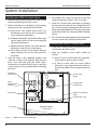
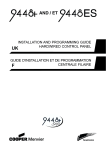
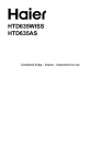
TS400 & TS410
Intruder Alarm Control Panels
1
2
UNSET
3
4
TAMPER FINAL EXIT
5
1
2
3
4
5
6
7
8
9
HOME
0
AWAY
Installation & Programming
Instructions
TS400/TS410 Installation Instructions
Contents
Overview
Introduction . . . . . . . . . . . . . . . . . . . . . . . . . 3
TS400 Features . . . . . . . . . . . . . . . . . . . . . . . 3
TS410 Features . . . . . . . . . . . . . . . . . . . . . . . 3
Specifications . . . . . . . . . . . . . . . . . . . . . . . . 3
TS400 Control Panel . . . . . . . . . . . . . . . . . 3
TS410 Control Panel . . . . . . . . . . . . . . . . . 3
Remote Keypad . . . . . . . . . . . . . . . . . . . . 3
Planning The Installation
General . . . . . . . . . . . . . . . . . . . . . . . . . . . . 4
Cable Routing . . . . . . . . . . . . . . . . . . . . . . . 4
TS400 Control Panel . . . . . . . . . . . . . . . . . . . 4
TS410 Control Panel . . . . . . . . . . . . . . . . . . . 4
External Sounder. . . . . . . . . . . . . . . . . . . . . . 4
Remote Keypad. . . . . . . . . . . . . . . . . . . . . . 4
Detection Devices . . . . . . . . . . . . . . . . . . . . 5
Passive Infra-Red (PIR) . . . . . . . . . . . . . . . . 5
Magnetic Contacts . . . . . . . . . . . . . . . . . 5
Personal Attack (PA) Button . . . . . . . . . . . . 5
Vibration Detectors . . . . . . . . . . . . . . . . . . 5
Smoke/Heat Detectors . . . . . . . . . . . . . . . 5
Final Exit . . . . . . . . . . . . . . . . . . . . . . . . . . . . 5
Auxiliary Tamper . . . . . . . . . . . . . . . . . . . . . . 5
Keyswitch . . . . . . . . . . . . . . . . . . . . . . . . . . . 5
System Installation
Installing the TS400 Control Panel . . . . . . . . . 6
Installing the TS410 Control Panel . . . . . . . . . 6
Mains Connection . . . . . . . . . . . . . . . . . . . . 7
Battery Connection . . . . . . . . . . . . . . . . . . . 7
PCB Layout . . . . . . . . . . . . . . . . . . . . . . . . . . 8
Multiple Detectors on the same Zone . . . . . 9
Door Contacts . . . . . . . . . . . . . . . . . . . . . 9
Passive Infra-Red. . . . . . . . . . . . . . . . . . . . 9
Auxiliary Tamper . . . . . . . . . . . . . . . . . . . . . . 9
Wiring Example. . . . . . . . . . . . . . . . . . . . . . . 10
Installing a Remote Keypad . . . . . . . . . . . . . 11
External Sounder Connections . . . . . . . . . . . 11
Extension Loudspeakers . . . . . . . . . . . . . . . . 12
ALM- Terminal . . . . . . . . . . . . . . . . . . . . . . . . 12
RST- Terminal. . . . . . . . . . . . . . . . . . . . . . . . . 12
Detector Reset (DTR RST) . . . . . . . . . . . . . . 12
Switched 12V (SW12V). . . . . . . . . . . . . . . . 12
2
Aux 12V Power . . . . . . . . . . . . . . . . . . . . . . . 12
SD1(Optional) . . . . . . . . . . . . . . . . . . . . . . . . 12
Initial Power-Up . . . . . . . . . . . . . . . . . . . . . . . 13
Programming
Programming Menus . . . . . . . . . . . . . . . . . . 14
Program Zones . . . . . . . . . . . . . . . . . . . . . . . 15
Alarm . . . . . . . . . . . . . . . . . . . . . . . . . . . . 15
Access . . . . . . . . . . . . . . . . . . . . . . . . . . . 15
Keyswitch . . . . . . . . . . . . . . . . . . . . . . . . . 15
Fire . . . . . . . . . . . . . . . . . . . . . . . . . . . . . . 15
P.A. . . . . . . . . . . . . . . . . . . . . . . . . . . . . . . 15
View Event Log . . . . . . . . . . . . . . . . . . . . . . . 15
Walk Test. . . . . . . . . . . . . . . . . . . . . . . . . . . . 15
Exit Time . . . . . . . . . . . . . . . . . . . . . . . . . . . . 16
Entry Time . . . . . . . . . . . . . . . . . . . . . . . . . . . 16
Bell Duration Time . . . . . . . . . . . . . . . . . . . . . 16
Change Engineer’s Passcode . . . . . . . . . . . 16
Remote Reset Number. . . . . . . . . . . . . . . . . 17
System Options. . . . . . . . . . . . . . . . . . . . . . . 17
Bell Output . . . . . . . . . . . . . . . . . . . . . . . . 17
Setting Mode . . . . . . . . . . . . . . . . . . . . . . 17
Reset Authority . . . . . . . . . . . . . . . . . . . . . 17
System Re-arms . . . . . . . . . . . . . . . . . . . . 17
Keyswitch Operation. . . . . . . . . . . . . . . . . 18
RST- Output . . . . . . . . . . . . . . . . . . . . . . . . 18
Returning to the Unset Mode . . . . . . . . . . . . 18
Full Setting the System (AWAY) . . . . . . . . . . . 18
Part-Setting the System (HOME) . . . . . . . . . . 18
Unsetting the System . . . . . . . . . . . . . . . . . . 18
Testing & Fault Finding
Testing the System . . . . . . . . . . . . . . . . . . . . 19
Fault Finding . . . . . . . . . . . . . . . . . . . . . . . . . 19
Chart 1 - Zone Faults . . . . . . . . . . . . . . . . . . 20
Chart 2 - System Will Not Set. . . . . . . . . . . . . 21
Chart 3 - External Sounder Faults . . . . . . . . . 22
Installation Records
System Programming Record. . . . . . . . . . . . 23
TS400/TS410 Installation Instructions
Overview
Overview
Introduction
The TS400 and TS410 are 6 zone microprocessor
based intruder alarm control panels with 5
programmable zones and a dedicated Final Exit
zone. The ease of operation for setting and
unsetting lends itself ideally to domestic and
smaller commercial installations.
TS400 Features
l
5 Programmable zones Night, Access, Fire, PA
& Keyswitch (plus common tamper)
l
Dedicated Final Exit zone
l
On board keypad and LED indicators
l
Up to 4 remote keypads
l
Facilities to connect to an SD1 Speech Dialler
l
4 event log
l
Programmable output for vibration detectors
or latching PIRs
l
Dual user codes
l
Remote Reset facility
l
2.1 Ah battery capacity
l
All data stored in Non-Volatile Memory (NVM)
TS410 Features
l
5 Programmable zones Night, Access, Fire, PA
& Keyswitch (plus common tamper)
l
Dedicated Final Exit zone
l
Blind control panel supplied with 1 remote
keypad with the option to support up to 4.
l
Facilities to connect to an SD1 Speech Dialler
l
4 event log
l
Programmable output for vibration detectors
or latching PIRs
l
Dual user codes
l
Remote Reset facility
l
7.0 Ah battery capacity
l
All data stored in Non-Volatile Memory (NVM)
Specifications
TS400 Control Panel
Input Voltage:
Current:
Power Supply:
Standby Battery:
Dimensions:
Material:
Weight:
Environment:
240V ±10% 50Hz
40mA (normal) 85mA (alarm)
750mA
2.1Ah
205 (W) x 205 (H) x 64 (D) mm
3mm polycarbonate
1.2 Kg
0 - 55°C
TS410 Control Panel
Input Voltage:
Current:
Power Supply:
Standby Battery:
Dimensions:
Material:
Weight:
Environment:
240V ±10% 50Hz
40mA (normal) 85mA (alarm)
750mA
7.0Ah
242 (W) x 237 (H) x 86 (D) mm
1.2mm mild steel
2.6 Kg
0 - 55°C
Remote Keypad
Current:
Dimensions:
Material:
Weight:
Environment:
35mA (normal) 50mA (alarm)
130 (W) x 130 (H) x 30 (D) mm
3mm Polycarbonate
415g
0 - 55°C
3
Planning The Installation
TS400/TS410 Installation Instructions
Planning The Installation
General
The TS400 and TS410 are flexible systems, but care
must be taken in planning the installation to
provide maximum protection with minimum
effort.
Survey the household and determine where each
security device is to be fitted. Wherever possible,
try to conceal wiring (e.g., in the loft, under carpets
or floorboards and inside cupboards). Commit the
system design to paper for future reference.
Cable Routing
When installing cables, the following should be
noted:
l
Ensure that all cables are kept clear of mains
supply cables, telephone cables, cables
supplying bells or sounders and any cables
likely to induce electrical noise (R.F.) into the
system.
l
Screened cable may prove necessary if
cables are run adjacent to cables which carry
R.F. (electrical noise) or are switching high
current loads.
l
The mains power supply cable to the system
must be connected to an un-switched fused
spur that cannot be accidentally switched off.
The mains cable must enter the control panel
housing via its own cable entry point.
TS400 Control Panel
The TS400 control panel should be located in a
position where it has easy access for the users to
set and unset the system. It should by mounted at
a level where it is easy to operate the keypad and
read the indicator LEDs. The provision for
connecting to a permanent mains supply must
also be considered.
When operating the system it should be possible to
hear the exit and entry tones throughout the entry
& exit route and outside the final exit door. If the
control panel is positioned a long way from the
final exit door, it may be necessary to fit an
extension loudspeaker.
4
TS410 Control Panel
The TS410 control panel is blind panel and as such
it can positioned out of view, normally in a
cupboard under the stairs. The provision for
connecting to a permanent mains supply must
also be considered.
When operating the system it should be possible to
hear the exit and entry tones throughout the entry
& exit route and outside the final exit door. If the
remote keypad is located a long way from the
final exit door, it may be necessary to fit an
extension loudspeaker.
External Sounder
The external sounder should be mounted as high
as possible so that it is visible and out of reach to
potential intruders. A six-core cable is required for
connection to the sounder which should enter
directly through the wall and into the sounder via
the cable entries in the back plate. However, if the
cable is run over the surface to the sounder then it
should be protected (e.g., the cable may be run
in aluminium conduit).
Remote Keypad
If required, up to four remote keypads may be
connected to the system to allow remote
operation of the system. The remote keypad has 8
LED indicators and an internal sounder to indicate
all system tones. Remote keypads require a
six-core cable for connection.
TS400/TS410 Installation Instructions
Detection Devices
There are several types of detection devices
available which are suitable for domestic
installations as follows:
Passive Infra-Red (PIR)
A detector which detects movement of an
intruder by the change in infra-red body heat.
When fitting PIRs, refer to the installation instructions
supplied with the unit. In general there are two
types of PIR "Standard" and "Latching". Normally
the standard type is used where one detector per
zone is fitted and a six-core cable is required for
connection. The latching type is used when more
than one detector is fitted to a zone, the latch
facility allows the user to identify the triggered
detector by means of the indicator LED on the
detector "latching" on. If latching detectors are
used an eight-core cable is required for
connection.
Magnetic Contacts
Magnetic contacts consist of an electrical switch
which is operated by a magnet. They come in two
versions, the "Flush" type is designed to be fitted
into the top or side of the door/window. The
"S u r face" type i s de si g ned to fi tted to
doors/windows where it is not possible to use flush
contacts e.g. garage doors, UPVC windows etc.
Both types of contacts require a four-core cable
for connections.
Personal Attack (PA) Button
Normally PA buttons are located by the front door
or adjacent to the bed, and preferably out of
reach to small children. Pressing the button at any
time will generate a full alarm. Some PA buttons
auto reset and some require a key to reset them. In
both cases the control panel must be reset. PA
buttons require a four-core cable for connections.
Planning The Installation
Smoke/Heat Detectors
12V Smoke or heat detectors may be connected
to the system to provide additional protection
against fire. When activated a distinctive internal
sounder tone is generated and the external
sounder is pulsed. Smoke detectors require a
four-core cable for connections.
Final Exit
This is the point at which the user leaves and enters
the premises (normally the front door). When
setting the system the user must leave the
protected area via the exit route and through the
Final Exit zone. When re-entering the premises the
user must activate the Final Exit zone to start the
entry timer which allows the user time to gain
access to the control panel to unset the system. If
the user enters the premises through any other
point and triggers a detection device a full alarm
will be generated. The sy stem may be
programmed to set after the exit timer has expired
or by the operation of the Final Exit detection
device.
Auxiliary Tamper
The tamper protection for all zones and any
auxiliary devices such as the speech dialler must
be wired in a continuous loop and then be
connected to the auxiliary tamper terminals.
Keyswitch
An optional keyswitch may be fitted to the system
to allow the user to set and unset (or part-set and
unset) the system using a physical key rather than
a four digit passcode.
Vibration Detectors
Vibration detectors are normally fitted to windows
or door frames. They are triggered when the
device senses a shock attack. Vibration detectors
require a six-core cable for connections.
5
System Installation
TS400/TS410 Installation Instructions
System Installation
Installing the TS400 Control Panel
1. Remove the screw from the top of the control
panel and lift away the front cover.
2. Ensure that there is no battery in the housing,
then remove the circuit board as follows:
(a) Disconnect the yellow leads from the
transformer and remove the connections
to the internal loudspeaker.
(b) Pull down the plastic clip at the bottom right
hand corner of the circuit board and gently
lift the board forward.
(c) Repeat with the plastic clip at the bottom
left hand corner of the circuit board.
(d) The bottom of the circuit board will then
swing forward and can be removed from
the base.
3. Hold the base in the required position and
mark the centre of the keyhole. Remove the
base, then drill and plug the holes. Note:
Remember to allow enough room to get the
cover screw in to top of panel when mounting
the base.
4. Re-position the base and secure to the wall
using not less than 30mm x No 10 screws.
5. Re-fit the circuit board assembly by aligning
the top of the board into the 2 supports in the
top of the housing ensuring that the edges of
the board sit between the 2 flanges, then push
the bottom of the circuit board until it clicks into
place.
6. Re-connect the yellow leads to the transformer
and re-connect the internal loudspeaker.
Installing the TS410 Control Panel
1. Open the control panel by removing the two
screws from the front cover.
2. Note the position of the cable entries as
follows:
(a) Seven 20mm cable entries for detection,
alarm and remote keypad cables.
(b) A 20mm cable entry for mains (240V)
below the mains input terminal block on
the left hand side of the control panel back
box.
Holders for
spare fuses
PCB location
flange
Fused
terminal block
(200mA)
Loudspeaker
(under PCB)
Transformer
Printed Circuit Board
(PCB)
PCB retention clips
-
+
Cover clips
Figure 1
6
TS400 Control Panel Assembly
Standby battery
2.1 Ah max.
+
TS400/TS410 Installation Instructions
System Installation
The mains cable must enter the control
panel through its own cable entry and
must not be mixed with other cables.
3. Hold the control panel back box in the required
position (keyhole to the top) and mark the
centre of the keyhole position. Remove the
back box, drill and plug the hole.
4. Screw a No 10 screw into the plugged hole.
Re-position the back box and mark the
remaining securing holes. Remove the back
box, drill and plug the holes.
5. Re-position the back box and pass all cables
into the base via cable entries, grommeting as
appropriate.
6. Secure the back box using not less than 30mm
x No 10 screws.
+
When replacing the cover, always
ensure that the earth bonding lead is
connected to the spade connection
inside the control panel.
Mains Connection
The mains supply is connected to a 3 way "Euro
Type" fused terminal block, which is fitted with a
200mA fuse. All electrical connections should be
carried out by a qualified electrician and must
comply with the current IEE regulations.
+
+
To comply with european regulations the
supply should be fed from a readily
accessible disconnect device, e.g.
un-switched fused spur fitted.
When making mains connections it should
be ensured that if the cable slips in such a
way as to place a strain on the conductors,
the protective earthing conductor will be
the last to take the strain.
Battery Connection
A suitable standby battery must be fitted to the
system to allow it to function during a mains fail
condition. The TS400 and TS410 are equipped with
a "Battery Protection" circuit so that if a battery is
accidentally reverse connected or its voltage is
below 4V, a tamper alarm is generated. To clear
the fault simply reconnect or replace the battery
as appropriate.
Fused
terminal block
(200mA)
Spade connection
for earth lead to front
cover
Transformer
Standby battery
7.0 Ah
Printed Circuit Board
(PCB)
Standby battery
2.1 Ah
Figure 2
TS410 Control Panel Assembly
7
System Installation
TS400/TS410 Installation Instructions
PCB Layout
Tamper switch
ALM
-
VOLUME
Home alarm
inhibit link
1
2
3
4
UNSET
TAMP
F/E
5
Factory Restart Pins
FACTORY
RESTART
Remote Keypad
Interface Connector
(1AMP)
AUX 12V
Leads to
transformer
HOME ALM
INHIBIT
Bell (1AMP)
Zone
connections
RSTTRG STB + H/O - TMP AUX L/S AUX 12V
FIRE K'SW ACCESS ACCESS
P.A.
- ZONE 5 ZONE 4 ZONE 3 ZONE 2 ZONE 1 F/EXIT
- TAMPER - +
EXTERNAL BELL
External
sounder
connections
Indicator LEDs
R37
Cut R37 to reduce
volume
1
2
3
4
5
6
7
8
9
HOME
0
AWAY
Keypad
(Not fitted on TS410)
A.C.
Figure 3
TS400 & TS410 Connection Diagram
Bell Fuse
This 1 Amp fuse protects the supply to the external
sounder/bell.
Aux Fuse
This 1 Amp fuse protects the supply to devices
power from the auxiliary 12V terminals.
Speaker Volume R37
Cut R37 to reduce the volume of the extension
loudspeakers.
Factory Restart Pins
If these pins are shorted during power-up all
system programming data is restored to the
factory default values, see page 13 for defaults.
Home Inhibit Link
When the link is open the [ALM-] terminal activates
when an alarm occurs during a full or part set
condition. When the link is closed the [ALM-]
terminal activates only if an alarm occurs during a
full set condition.
8
1 - 5 Indicator LEDs
These red indicator LEDs indicate the alarm status
of zone 1 - 5. Note these are not fitted on the
TS410.
Unset Indicator LED
This green indicator LED is used to indicate the
status of the system set or unset. It also flashes
when the mains power is removed or when the
user selects the user program mode
Tamp Indicator LED
This red LED is used to indicate a system tamper
alarm, it also flashes when the engineer program
mode is selected. Note this is not fitted on the
TS410.
F/E Indicator LED
This red LED is used to indicate the status of the final
exit zone. Note this is not fitted on the TS410.
TS400/TS410 Installation Instructions
System Installation
To tamper loop
for other zones
AUX
TAMPER
ZONE
Connecting several
flush contacts per zone
Flush Contact
Flush Contact
To tamper loop
for other zones
AUX
TAMPER
ZONE
Surface Contact
Surface Contact
LATCH
0V
+12V
TAMPER
ALARM
LATCH
+12V
0V
Program [RST-] as
SW 12V
PIR
RST -
TAMPER
PIR
ALARM
Connecting several
suface contacts per zone
To tamper loop
for other zones
AUX
TAMPER
AUX
12V
+ -
Connecting several
PIRs per zone
ZONE
Figure 4
Connecting Multiple Detectors per Zone
Multiple Detectors on the same Zone
Door Contacts
When connecting more than one door contact to
a zone, the alarm contacts must be connected in
series. The switch inside the contact is connected
between the two plated screws (shown in white in
the above figure).
Passive Infra-Red
When connecting more than one PIR to a zone it is
recommended that you use "Latching" type PIRs.
The latch terminal on the PIR is connected to the
[RST-] output which must then be programmed as
SW 12V.
Auxiliary Tamper
The tamper wires for each detector must be
connected in series using a terminal strip or similar
and then connect to the AUX TAMPER terminals.
Tamper Loop
Tamper Loop
Tamper Loop
AUX
TAMPER
Tamper Loop
Terminal Strip (Not Supplied)
Figure 5
Auxiliary Tamper Connection
9
System Installation
TS400/TS410 Installation Instructions
Wiring Example
External Sounder
TS400 / TS410
TRIGGER STROBE HOLD OFF +
HOLD OFF TAMPER RETURN -
ALARM
PIR
To ZONE 1
R37
ALM RST TRG STB+
- H/O
TMP AUX
TAMPER
L/S + AUX 12V
-
Terminal strip
(not supplied)
TAMPER
0V
+12V
To AUX -12V
To AUX +12V
ZONE 5 (P A)
ZONE 4 (Fire)
ALARM
PIR
To ZONE 2
ZONE 3 (K/Sw)
TAMPER
ZONE 2 (Access)
0V
+12V
To AUX -12V
To AUX +12V
ZONE 1 (Access)
FINAL EXIT
To ZONE 3
Surface Contact
To FINAL EXIT
Flush Contact
To ZONE 5 (P.A.)
P.A. Button
Note
Any unused zones must be
linked out.
PIRs and surface contacts can
be connected to any zone. This
diagram is only used to
represent a typical installation
example.
If a keyswitch is fitted, it must
be connected to ZONE 3 and
then programmed as
KEYSWITCH.
If a smoke/heat detector is
fitted, it must be connected to
ZONE 4 and then programmed
as FIRE.
If a P.A. button is fitted, it must
be connected to ZONE 5 and
then programmed as P.A.
Smoke Detector
Supply +
Supply ALARM
Figure 6
10
Example Wiring Diagram
To AUX +12V
To AUX -12V
To ZONE 4 (Fire)
16 Ohm Extension loudspeaker
(cut R37 to reduce volume)
TS400/TS410 Installation Instructions
Installing a Remote Keypad
Ensure that the mains and battery power has been
disconnected and proceed as follows:
1. Connect each core of the 6-core cable to the
interface terminals "L E D C B A" (make a note of
the colours used for each connection).
2. Pass the yellow flying-lead behind the PCB and
connect it to the [L/S-] terminal.
3. Plug the Interface board into the interface
socket as shown below.
System Installation
the last or furthest remote keypad does not
exceed 50 metres).
7. Carefully reattach the front cover assembly to
the remote keypad base ensuring that all
cables are clear of the tamper switch spring
and the cover is securely clipped to the base.
External Sounder Connections
The following terminals have been provided to
allow connections to an external sounder:
H/O -
Flying-lead
This is used to provide a permanent -ve
hold off to external sounders, strobes etc.
H/O + This is used to provide a permanent +ve
hold off to external sounders, strobes etc.
It is protected by a 1 Amp fuse (Bell 12V).
This is the negative tamper return
connection from the external sounder. If
an external sounder is not fitted this input
must be linked to [H/O -].
STB -
This is the strobe output which switches to
0V on alarm. The output is rated at 500mA
and should be connected to -ve strobe
trigger input on the external sounder.
TRG -
This is the external sounder trigger output
which is rated at 500mA. This output can
be programmed for SAB o r SC B
operation, as follows:
SAB: TRG - will switch to 0V on alarm and
will provide a maximum of 500mA.
SCB: TRG - will provide a negative hold
off (500mA), which is removed on alarm.
L/S
TMP -
Flying-lead
connected to L/S Figure 7
Interface PCB
Remote Interface Connections
4. Separate the remote keypad cover and base
by using a screwdriver to push two of the clips
(top or bottom) inwards from the cover
retaining slots. Then lift the cover assembly,
noting that the circuit board is connected to
the under side of the cover.
5. Hold the remote keypad base in position
(keyhole to the top) and mark the three
securing holes, drill and plug the wall as
required. Pass the 6-core cable into the base
via the cable entry points as appropriate and
secure the base to the wall.
6. Connect each core of the 6-core cable to the
remote keypad terminals "L A B C D E", ensuring
that the connections through to the control
panel are A to A, B to B, etc. If more remote
keypads are to be fitted, they may be
connected i n a star o r dai sy chain
configuration (providing the cable length to
Typical
External Sounder
12V +
0V
Tamper In
Tamper Out
Strobe +ve
Strobe -ve
Trigger -ve
Figure 8
Control
Panel
H/O +
H/O TMP STB TRG -
External Sounder Connections
11
System Installation
TS400/TS410 Installation Instructions
Extension Loudspeakers
Aux 12V Power
A 16Ohm extension loudspeaker can be
connected between the [L/S-] and [AUX 12V+]
terminals. R37 (located in the top left hand corner
of the PCB) can be cut to reduce the volume of
the internal sounders (alarm is always full volume).
16 Ohm Loudspeaker
Figure 9
L/S AUX +12V
Speaker Connections
ALM- Terminal
This terminal is switched negative (100mA) on
alarm and is removed when the system is reset. If
the Link marked "HOME ALARM INHIBIT" on the main
PCB is closed, the [ALM-] output is disabled when
the system is part-set (Home). Normally this output
is used to trigger a speech dialler or similar.
RST- Terminal
The auxiliary 12V terminals provide a permanent
12V supply for detectors which require a low
voltage supply e.g., PIRs, vibration detectors,
smoke detectors etc. The output is protected by a
1 Amp fuse (Aux 12V).
The maximum available current from the control
panel power supply is 750mA. The following is a
typical example showing how to calculate the
available auxiliary current.
Control Panel
= 85mA
External Sounder
= 250mA
External Strobe
= 115mA
Total
= 450mA
Auxiliary Available = 300mA (750 - 450)
SD1(Optional)
The SD1 is a customer programmable speech
dialler which dials pre-programmed numbers to
inform neighbours etc. of the alarm. It is capable
of transmitting up to 3 messages linked to inputs A,
B and C.
This terminal may be programmed as:
Detector Reset (DTR RST)
SD1
When programmed as Detector Reset the output
may be used for detectors which latch their alarm
condition, and must be de-powered to reset (e.g.,
smoke detectors, vibration detectors etc.). Power
for such detectors must be connected between
[AUX 12V] and [RST-].
TRIG C
Switched 12V (SW12V)
When programmed as Switched 12V the output
may be connected to the latch input terminal on
latching detectors (e.g., PIRs etc.). This feature is
normally used when more than one detector is
connected to a single zone. It allows the user to
identify the alarm source by latching the indicator
LED on the detector that caused the alarm
activation. The latched LED will clear when the
system is reset.
12
TS400/TS410
Set TRIG POLARITY to -ve
BOX
TAMPER
+12V
0V
TRIG B
TRIG A
ALM RST TRG STB+
- H/O
TMP AUX
TAMPER
L/S + AUX 12V
ZONE 5 (P A)
ZONE 4 (Fire)
Note: Only connect TRIG A (FIRE)
and TRIG B (PA) if zones 4 and 5
are programmed as Fire and PA.
Figure 10
SD1 Connections Details
TS400/TS410 Installation Instructions
Initial Power-Up
1. Place a small screwdriver blade between the
pins on the control panel PCB, marked
FACTORY RESTART (located just below the LEDs).
This will ensure the factory defaults are loaded
as shown below:
Engineer Code
1234
User Code 1
5678
Zone 1
Alarm
Zone 2
Access
Zone 3
Alarm
Zone 4
Alarm
Zone 5
Alarm
Exit Time
30 Seconds
Entry Time
30 Seconds
Bell Duration
20 Minutes
Bell Output
SAB (-ve applied)
Remote Reset Number
004
Setting Mode
Timed Set
Reset Authority
User Reset
Number Of Rearms
3
Operation Of Keyswitch
Away Set (Full)
RST- Output
Detector Reset
HOME Set Configuration
Zone 1 Omitted
+
System Installation
On the TS410 you MUST connect the earth
bonding cable from the front cover to the
spade connection point, see figure 2.
6. Fit the battery link in the external sounder and
replace cover.
7. The system is now ready for programming.
Factory Default Settings
2. Switch on the 240V mains supply, when the
green UNSET LED is lit remove the screwdriver
blade. The internal alarm will sound and the
TAMPER LED will light.
3. Enter the engineer’s passcode (default 1 2 3 4),
the alarm will silence. Enter the engineers
passcode again and the TAMPER LED will flash
(engineer programming menu selected).
4. Connect the standby battery. If the TAMPER
LED lights permanently and the internal alarm
sounds when the battery is connected, then it
may be incorrectly connected or it may be
totally discharged. Disconnect the battery
immediately and reconnect or replace as
appropriate.
5. Push the battery into place at the bottom of the
housing and re-fit the front cover.
13
Programming
TS400/TS410 Installation Instructions
Programming
Programming Menus
There are two programming menus within the system. The engineer’s programming menu and the user
programming menu. The figure below shows the structure of both programming menus, however the
engineers programming menu is only covered in full detail within this manual. For full details on the user
options see "User Operating Instructions".
Engineer's Menu
1
2
UNSET
3
TAMPER
4
FINAL EXIT
User Menu
5
1
14
2
UNSET
3
TAMPER
4
FINAL EXIT
5
3
TAMPER
4
FINAL EXIT
5
Enter first 3 digits of passcode then
(e.g., 5 6 7 HOME )
Enter the engineer's passcode
(default = 1 2 3 4 )
1
2
UNSET
Tamper
LED
Flashes
1
2
UNSET
3
TAMPER
4
FINAL EXIT
5
Unset
LED
Flashes
1
= Program Zones
1
= Bell Test
2
= View Event Log
2
= Walk Test
3
= Walk Test
4
= Change Passcode 1
4
= Exit Time
6
= Change Passcode 2
5
= Entry Time
7
= Home Set Configuration
6
= Bell Duration
0
= Return to unset mode
7
= Engineer's Passcode
8
= Remote Reset No.
9
= System Options
0
= Return to unset mode
AWAY
= Full set the system
HOME
= Part set the system
HOME
Press HOME twice when the system
is in the unset mode to select
"Chime" zones.
TS400/TS410 Installation Instructions
Program Zones
The TS400 zones may be programmed so that
they perform different functions. The zones types
are as follows:
Alarm
Zones 1- 5 can be programmed as alarm zones,
this type of zone will only generate a full alarm
when activated during a set condition.
Programming
➤ To program zones proceed as follows:
1. Ensure that the engineer’s menu is selected,
then press [1] to select program zones.
2. Press keys [1] to [5] to toggle between the two
options for each zone as shown below.
Zone LED
LED On
LED Off
Zone 1
Access
Alarm
Zone 2
Access
Alarm
Access
Zone 3
Keyswitch
Alarm
Zones 1 and 2 can be programmed as access
zones, this type of zone is automatically isolated
during the entry/exit procedure to allow a walk
through route for the user. Once the system is full
set the access zones respond as alarm zones. If an
access zone is armed during the part set (Home)
condition it will start the entry timer if activated.
Zone 4
Fire
Alarm
Zone 5
PA
Alarm
Keyswitch
Zone 3 can be programmed as a keyswitch zone,
this type of zone will set the system when active
(zone open) and unset the system when healthy
(zone closed). The keyswitch zone functionality
can be further programmed to either full set
(Away) or part set (Home) the system, see "System
Options" on page 17.
Fire
Zone 4 can be programmed as a fire zone, this
type of zone is monitored at all times, when
activated a distinctive internal sounder tone is
generated and the external sounder is pulsed on
and off. The internal and external sounders will
operate for 20 minutes, irrespective of the bell
duration setting.
P.A.
Zone 5 can be programmed as a Panic Alarm
(P.A.) zone, this type of zone is monitored at all
times, when activated a full alarm is generated.
The internal and external sounders will operate for
20 minutes, irrespective of the bell duration
setting.
3. When completed, press [0] to accept, a high
pitched acceptance tone will be heard and
the system returns to the engineer’s menu.
View Event Log
The TS400 will store up to 4 alarm activation events
within the memory log. This option allows the
events to be viewed.
➤ To view the event log proceed as follows:
1. Ensure that the engineer’s menu is selected,
then press [2] to select view event log.
2. Press [1] to view the newest event, [4] to view
the oldest event etc.
3. When completed, press [0] to accept, a high
pitched acceptance tone will be heard and
the system returns to the engineer’s menu.
Walk Test
The Walk Test option allows the engineer to test the
function of all detection zones without causing an
alarm. As each zone is activated its zone indicator
LED will light and the internal sounder generates a
two-tone sound. When the zone is deactivated the
sounder stops and the zone LED goes out.
➤ To perform a walk test proceed as follows:
1. Ensure that the engineer’s menu is selected,
then press [3] to select walk test.
2. Activate each zone in turn by opening doors
fitted with alarm contacts and walking in front
of movement detectors.
3. When completed, press [0] to accept, a high
pitched acceptance tone will be heard and
the system returns to the engineer’s menu.
15
Programming
TS400/TS410 Installation Instructions
Exit Time
Bell Duration Time
This timer sets the delay between the user initiating
the setting procedure and the system actually
setting. This only applies when the system is
programmed to set by "Timed Exit", see "System
Options" on page 17.
This timer controls the duration of the external
sounder when the system is triggered into a full
alarm condition.
➤ To program the exit time proceed as follows:
1. Ensure that the engineer’s menu is selected,
then press [6] to select the bell duration time.
1. Ensure that the engineer’s menu is selected,
then press [4] to select Exit Time.
2. Select the required exit time by using keys [1] to
[4] to light the appropriate zone LED. When the
LED is lit the exit time will be as shown below:
➤ To program the bell duration time proceed as
follows:
2. Select the required bell duration time by using
keys [1] to [4] to light the appropriate zone
LED. When the LED is lit the bell duration time will
be as shown below:
Zone LED
LED On
Zone LED
LED On
Zone 1
10 Seconds
Zone 1
90 Seconds
Zone 2
30 Seconds
Zone 2
3 Minutes
Zone 3
1 Minute
Zone 3
10 Minute
Zone 4
2 Minutes
Zone 4
20 Minutes
Zone 5
Continuous
3. When completed, press [0] to accept, a high
pitched acceptance tone will be heard and
the system returns to the engineer’s menu.
3. When completed, press [0] to accept, a high
pitched acceptance tone will be heard and
the system returns to the engineer’s menu.
Entry Time
When the entry procedure is initiated, the Entry
Timer is started. If a valid user passcode is not
entered when the timer reaches zero, a full alarm
tone is generated from the internal sounders only
and the timer is restarted. If a valid user passcode
is not entered when the timer reaches zero for the
second time the external sounder is activated.
➤ To program the entry time proceed as follows:
1. Ensure that the engineer’s menu is selected,
then press [5] to select entry time.
2. Select the required exit time by using keys [1] to
[4] to light the appropriate zone LED. When the
LED is lit the entry time will be as shown below:
Zone LED
LED On
Zone 1
10 Seconds
Zone 2
30 Seconds
Zone 3
1 Minute
Zone 4
2 Minutes
3. When completed, press [0] to accept, a high
pitched acceptance tone will be heard and
the system returns to the engineer’s menu.
16
Change Engineer’s Passcode
The factory default engineer’s passcode is set to
[1] [2] [3] [4], but the installation engineer should
change this to their own personal 4 digit passcode
as follows:
➤ To change the engineer's passcode proceed
as follows:
1. Ensure that the engineer’s menu is selected,
then press [7] to select change engineer’s
passcode.
2. Zone LEDs 1 to 4 will now light.
3. As the new passcode is entered each LED will
go out one by one. When all 4 digits have
been entered, LEDs 1 to 4 will light again and
the new passcode must be re-entered for
confirmation.
4. A high pitched tone indicates the new
passcode was accepted, a low pitched tone
indicates the passcode was not accepted. If
the passcode was not accepted repeat the
procedure again, using a different passcode.
TS400/TS410 Installation Instructions
Remote Reset Number
The "Engineer Reset" option can be overridden by
the user, operating the "Remote Reset" facility. If
an alarm is generated the system will respond with
a four digit "seed" code which the user quotes to
the alarm company. The "seed" code is then
entered into a decoder and a unique "Remote
Reset" code is generated. This is passed back to
the user and, on entering the "Remote Reset"
code, the system will reset.
The "Remote Reset" code is generated using an
algorithm identified by a 3 digit number.
Alternative algorithms may be selected but these
must correspond to that used by the alarm
company otherwise the "Remote Reset" code will
be incorrect. The "Remote Reset" feature may be
disabled altogether by setting the number to
"000".
➤ To program the remote reset number
proceed as follows:
1. Ensure that the engineer’s menu is selected,
then press [8] to select remote reset number.
2. Zone LEDs 1 to 3 will now light.
3. As the new remote reset number is entered
each LED will go out one by one. When all 3
digits have been entered, LEDs 1 to 3 will light
again and the new number must be
re-entered for confirmation.
4. A high pitched tone indicates the new number
was excepted, a low pitched tone indicates
the number was incorrectly entered and the
procedure must be repeated.
System Options
There are six system options which change the
functionality of the alarm system. The options are
as follows:
Bell Output
Programming
Setting Mode
The system can be programmed to set using
ether:
Timed Exit: The system will set when the exit timer
has expired.
Final Exit: The system will set when the last
detector or door contact is activated during the
exit procedure. Note: When the system is part set
(HOME) the system will always set by timed exit and
is silent.
Reset Authority
The person responsible for resetting full alarms can
be programmed as either:
User: Following a full alarm the system can be
reset by the user.
Engineer: Following a full alarm the system can
only be reset by the engineer or Remote Reset (If
enabled).
System Re-arms
The system can be programmed to re-arm after
an alarm. The re-arm options are:
1 re-arm: When an alarm occurs, the internal
and external sounders are operated for the length
of the bell duration. At the end of this time the
alarm is silenced and the all zones are re-armed.
Any zones that are active will be automatically
isolated until they return to their healthy state. If an
alarm occurs from the same zone it will cause the
internal and external sounders to operate again,
at the end of the alarm the zone is "Locked-out"
and prevented from generating another alarm. All
other healthy zones will re-arm and will only be
‘Locked-out’ when they have caused another
alarm.
3 Re-arms: Operates as above, but zones are
only "Locked-out" after the system has re-armed 3
times.
The bell trigger output [TRG-] can be programmed
as either:
SAB: When programmed as SAB the output will
switch to 0V on alarm.
SCB: When programmed as SCB the output
provides a 0V hold off, which is removed on alarm.
17
Programming
TS400/TS410 Installation Instructions
Keyswitch Operation
Returning to the Unset Mode
The operation of the keyswitch (zone 3) can be
programmed as either:
AWAY: When keyswitch zone is opened the exit
procedure for AWAY set will start and the system will
attempt to full set. When the zone is closed the
system will unset.
HOME: When the key switch zone is opened the
exit timer will start and when the timer has expired
the system will be part set. When the zone is closed
the system will unset.
RST- Output
The operation of the [RST-] output can be
programmed as either:
SW 12V: This can be connected to the "Latch"
input on latching detection devices.
Detector Reset: This can be used as the 0V
connection to detectors that require the power to
be removed to reset them (such as smoke
detectors and vibration sensors).
➤ To program the system options proceed as
follows:
1. Ensure that the engineer’s menu is selected,
then press [9] to select system options.
2. Press keys [1] to [6] to toggle the zone LEDs on
or off. The system options will be set according
to the status of the relevant zone LED as shown
below:
Zone LED
LED On
LED Off
Zone 1
Bell output is an
SAB
Bell output is an
SCB
Zone 2
System is set by
Final Exit
System is set by
Timed exit
Zone 3
System is reset
by the Engineer
System is reset
by the User
Zone 4
System re-arms
three times
System re-arms
once
Zone 5
Keyswitch =
Home set
Keyswitch =
Away set
Final Exit
RST output is
SW12V
RST output is
Detector Reset
3. When completed, press [0] to accept, a high
pitched acceptance tone will be heard.
18
Once all the engineer programming is completed
the system can be returned to the unset mode by
pressing the [0] key. The user passcodes and
"HOME" set configuration must also be
programmed, see the "User Guide" for full details.
Full Setting the System (AWAY)
The engineer can use his passcode to full set the
system as follows:
1. Ensure that the engineer’s menu is selected,
then press [AWAY] to full set the system.
2. The exit tone will start and the Final Exit LED will
flash.
3. When the exit tone stops, the system is full set.
Part-Setting the System (HOME)
The engineer can use his passcode to part set the
system as follows:
1. Ensure that the engineer’s menu is selected,
then press [HOME] to part set the system.
2. The Final Exit LED will flash (HOME set is always
silent and timed).
3. When the high pitched tone is heard the
system is part set.
Unsetting the System
The engineer can only use his passcode to unset
the system when the system is set or part set using
the engineer passcode (i.e., if the system is set by
the user the engineer passcode will NOT unset the
system).
1. Enter via the prescribed entry route.
2. The entry tone will start and the Final Exit LED will
flash.
3. Enter the engineer’s passcode (e.g., 1 2 3 4 ).
4. The entry tone will stop and the unset LED will
light.
TS400/TS410 Installation Instructions
Testing & Fault Finding
Testing & Fault Finding
Testing the System
Fault Finding
Once the system has been installed and fully
programmed it can be tested. Before performing
any tests it is advisable to warn your neighbours of
any tests that involve using the external sounder.
If you have carefully followed the installation and
wiring instructions and carried out the various
checks correctly, your security system will now be
fully operational.
1. Perform a WALK TEST to ensure that all zones are
operating correctly.
However if the system is not operating correctly
when you have completed the installation, or it
has developed a fault after a period of trouble
free operation, the Fault Finding Charts will help
you identify and clear the fault.
2. Perform a BELL TEST to ensure that the external
sounder and strobe is operating correctly (See
"User Operating Instructions" for details on BELL
TEST).
3. Set the alarm system. Open a door or activate
a detector to create an alarm.
Before using the fault finding charts refer to the
following notes:
l
When removing covers from the control
panel, external sounder or detectors you must
remember to first enter the four digit engineer
code into the control panel.
l
When all tests are complete, remember to
replace all covers etc.
l
A battery operated circuit tester available
from most hardware and DIY stores, or a
simple battery bulb and length of wire, will
assist in checking the continuity of circuit
wiring, if necessary.
4. Unset the system to silence the internal and
external sounder.
5. Ensure the correct zone LED is lit, then enter the
passcode again to clear the indications.
Installation and checks are now complete, if there
are any problems in your installation refer to the
section on Fault Finding.
19
Testing & Fault Finding
TS400/TS410 Installation Instructions
Chart 1 - Zone Faults
Enter 4 digit
engineer code and
then press 3 to select
walk test mode
Permanent Zone
Fault
Remove control
panel front cover
and disable the case
tamper switch
Relevant zone LED
on and pulsed
sounder
No zone LED's on
and sounder is off.
Remove wiring from
faulty zone and link
with a piece of wire.
Activate the
relevant detector
Relevant zone LED
still on and pulsed
sounder.
No zone LED's on
and sounder is off.
Control Panel Faulty.
Remove zone wiring
from detector and
twist together
If the control panel
sounder remains
silent, the fault is in
the detector
Relevant zone LED
light's and sounder
changes to a pulsed
tone.
No change in
control panel
indecations.
Remove the wiring
from the faulty zone.
Remove link from
faulty zone and re-fit
zone wiring.
20
Detectors Fail To
Operate
If the control panel
sounder is puled,
there is an open
circuit in the wiring.
No zone LEDs on
and sounder is off.
Control panel and
detector are OK.
Enable case tamper
and re-fit cover.
Relevant zone led
light and sounder
changes to a pulsed
tone
Control Panel Faulty
If the control panel
sounder remains
silent, there is a
short in the wiring.
Re-fit zone wiring at
control panel.
remove zone wiring
from detector
If the control panel
sounder is pulsed,
the fault is in the
detector
TS400/TS410 Installation Instructions
Testing & Fault Finding
Chart 2 - System Will Not Set
Enter 4 digit
engineer code and
then press 3 to select
walk test mode
Deactivate all
detectors & contacts
(e.g. close doors
etc.)
No zone LED's on
and sounder is off.
Press [0] to exit
Walk Test.
Zone LED on and
Pulse Sounder.
See Chart 1 on Zone
Faults
Press [HOME] or
[AWAY] to part set
or full set the system.
Tamper LED on.
Remove control
panel cover and
disable the case
tamper.
Remove wiring from
AUX TAMPER
terminals and link
with a piece of wire
If the Tamper LED
remains lit, fit link
between TMP- and
H/O -
If Tamper LED goes
out there is an open
circuit within the
AUX TAMPER wiring.
If the Tamper LED
remains lit ,
disconnect the
battery.
If tamper LED goes
out the tamper on
the external siren is
open.
If the Tamper LED
remains lit, the
control panel is
faulty.
If the Tamper LED
goes out the
battery is faulty
21
Testing & Fault Finding
TS400/TS410 Installation Instructions
Chart 3 - External Sounder Faults
Check PA buttons
are not depressed.
Ensure that the
system is in the
unset mode.
External siren will
not trigger when
performing a Bell
Test.
External Siren
sounds continuously.
Enter 4 digit
engineer code and
remove the control
panel cover.
If zone 5 LED is
on, the fault is
within the PA circuit.
(see chart 1)
Remove the wire
from the TRGterminal..
Remove the wire
from the TRGterminal.
Place the removed
wire on the H/Oterminal. The siren
should sound.
external siren sounds
continiously.
External siren stops.
Using a voltmeter
check this is
13 - 14V between
H/O+ & H/O-.
Check TRG- is
programmed for
correct type (SAB or
SCB).
If the siren did not
sound check
connections at the
siren
If there is no reading
check the Bell Fuse
hasn't blown.
Activate the
relevant detector
If the connections
are OK the fault is
likely to be within the
siren.
If voltage reads OK,
the fault is likely to
be within the siren
22
Enter 4 digit
engineer code and
remove the control
panel cover.
If the siren triggered
OK the fault is likely
to be within the
control panel.
TS400/TS410 Installation Instructions
Installation Records
Installation Records
Zone Programming
Zone
Type
Location
Chime
Home Config.
1
Alarm / Access
On / Off
Armed / Omitted
2
Alarm / Access
On / Off
Armed / Omitted
3
Alarm / Keyswitch
On / Off
Armed / Omitted
4
Alarm / Fire
On / Off
Armed / Omitted
5
Alarm / PA
On / Off
Armed / Omitted
On / Off
Always Armed
Final Exit
Timers
Exit Time
10 seconds
30 seconds
1 minute
2 minutes
Entry Time
10 seconds
30 seconds
1 minute
2 minutes
Bell Duration
90 seconds
3 minutes
10 minutes
20 minutes
Continuous
System Options
Bell Output
Setting Mode
Reset By
Re-arms
Keyswitch
RST Output
SCB
Timed
User
1 re-arm
Away set
Detector Reset
SAB
Final Exit
Engineer
3 re-arms
Home set
SW12V
Installer Information
Remote Reset No.
For Remote Reset Telephone:
Company Name:
Address:
Telephone No.:
Date Installed:
23
Key
Function
Action
LEDs
1
Zone Types
Press [1] - [5] to toggle
LEDs on/off.
Press [0] to end
1
2
3
4
5
2
View Log
Press [1] for newest event
Press [4] for oldest event
Zone LEDs that light have caused an alarm
3
Walk Test
Activate detectors.
Press [0] to end
When the zone is in alarm the panel will sound
and the relevant zone LED will light.
4
5
On
Z1 = Access
Z2 = Access
Z3 = Keyswitch
Z4 = Fire
Z5 = PA
10 seconds
30 seconds
1 minute
2 minutes
Exit Time
Press [1] to [4].
Press [0] to end
1
2
3
4
Entry Time
Press [1] to [4].
Press [0] to end
1
2
3
4
10 seconds
30 seconds
1 minute
2 minutes
1
2
3
4
5
90 seconds
3 minutes
10 minutes
20 minutes
Continuous
Off
Z1 = Alarm
Z2 = Alarm
Z3 = Alarm
Z4 = Alarm
Z5 = Alarm
6
Bell Duration
Press [1] - [5].
Press [0] to end
7
Change Engineer's
Passcode
Enter new passcode
twice
Zone LEDs 1 - 4 will light, as code is entered
each LED will go out one by one.
8
Remote Reset No.
Enter reset number twice
Zone LEDs 1 - 3 will light, as code is entered
each LED will go out one by one.
Press [1] - [6] to toggle
LEDs on/off
Press [0] to end
9
System Options
HOME
Part set the system
Leave via exit route
AWAY
Full set the system
Leave via exit route
0
Return to unset
1
2
3
4
5
F.Exit
Bell output = SAB
Set by Final Exit
Reset by Engineer
3 re-arms
Key = Home set
RST = SW12V
Bell output = SCB
Set by Timed Exit
Reset by User
1 re-arm
Key = Away set
RST = Det. Reset
Engineer's Quick Reference Programming Chart
Cooper Security Ltd, Security House,
Vantage Point Business Village,
Mitcheldean, Gloucestershire,
GL17 0SZ. England
Product Support Tel: +44 (0)1594 545556
Available between;
08:15 and 17:00, Monday to Thursday.
08:15 and 12:45 Friday. Emergency service only
between 12:45 and 17:00 Friday.
Product Support Fax: +44 (0)1594 545401.
www.coopersecurity.co.uk
18014
Drg. No. 33:1939:00 Issue 01 Doc 01 April 97