1
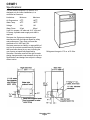
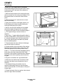
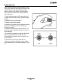
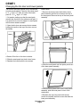
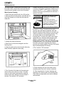
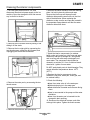
CSWE1
Introduction
This product manual is intended for users and
servicers of the CSWE1 Automatic Ice Machine.
Table of Contents
Specifications: . . . . . . . . . . . . . . . . . . . . . . . . . . . . . . . .
2
Installation: . . . . . . . . . . . . . . . . . . . . . . . . . . . . . . . . .
3
Plumbing: . . . . . . . . . . . . . . . . . . . . . . . . . . . . . . . . . .
4
Initial Start Up . . . . . . . . . . . . . . . . . . . . . . . . . . . . . . . .
5
Changing the bin door and lower panels.
. . . . . . . . . . . . . . . . . . . . .
6
. . . . . . . . . . . . . . . . . . . . . . . . . . . . . . .
7
. . . . . . . . . . . . . . . . . . . . . . . . . . . . . . . .
8
Cleaning the interior components. . . . . . . . . . . . . . . . . . . . . . . . .
9
Condenser
10
What to expect:
Maintenance:
. . . . . . . . . . . . . . . . . . . . . . . . . . . . . . . . .
Service Diagnosis
. . . . . . . . . . . . . . . . . . . . . . . . . . . . . .
11
Service Diagnosis
. . . . . . . . . . . . . . . . . . . . . . . . . . . . . .
12
Service Diagnosis
. . . . . . . . . . . . . . . . . . . . . . . . . . . . . .
13
Operational Characteristics . . . . . . . . . . . . . . . . . . . . . . . . . . .
14
Keep this manual for future reference.
A parts list is located in the center of this manual, printed on yellow paper.
This manual is printed on recycled paper.
December 1995
Page 1
CSWE1
Specifications:
This ice machine requires 115 volts AC. It is
designed only for indoor installations, in a
controlled environment.
Limitations:
Minimum
Maximum
Air Temperature
o
55 F.
100oF.
Water Temp.
40oF.
100oF.
Voltage
104
126
Water Press.
20 psi
80 psi
It will fit in a space 18" wide and 34.5 " high and
24" deep. A potable water supply and drain is
required.
Scotsman Ice Systems are designed and
manufactured with the highest regard for safety
and performance. They meet or exceed the
standards of UL, NSF and CSA.
Scotsman assumes no liability or responsibility of
any kind for products manufactured by Scotsman
that have been altered in any way, including the
use of parts not specifically approved by
Scotsman. Scotsman reserves the right to make
design changes and/or improvements at any time.
Specifications and designs are subject to change
without notice.
Refrigerant charge is 6.75 oz. of R-134a.
December 1995
Page 2
CSWE1
Installation:
Proper installation is a necessity, because an
improper installation will cause operational
problems that are NOT covered by any warranty. It
is the customer’s responsibility to contact a
qualified installer.
Proper electrical supply, water supply and floor
drain must be available. An electrical ground is
required.
Do NOT close in the front of the ice maker. The ice
machine requires space at the front base to
discharge warm air.
Electrical:
Follow all local, state and national codes. If
needed, obtain the services of a licensed
electrician.
1. A separate 115 volt, 15 amp circuit is
recommended. A ground is required.
2. Do not use an extension cord. Have a grounded
outlet installed close enough to the planned
installed position of the ice machine so that the ice
machine’s plug can be plugged in directly.
If required by sanitation codes, seal the cabinet to
the floor with an approved sealant. Legs are not
available for this machine.
Location:
The ice machine must be installed indoors, in a
controlled environment. There must be room to
open the ice machine door and room to move the
ice machine out for service, if needed.
The unit may be built in at the top, sides and back.
Cool Air In
Warm Air Out
December 1995
Page 3
CSWE1
Plumbing:
Connect a 1⁄4" OD copper tube to a threaded
compression fitting on the inlet water valve. There
is an access hole in the back of the cabinet for
routing the tube.
1. Remove the two screws in the lower grille area
and one screw from the center panel support. Pull
forward and down to remove the lower access
panel.
2. While the panel is off, rotate the fan to check
that it moves freely.
3. Open the ice bin door, and slightly loosen, but
Do Not Remove the thumb screws holding the
cutter grid and water pan in place.
4. Have a shut off valve installed on the potable
cold water supply tubing near the ice machine.
5. Connect to the shut off valve sufficient length of
1⁄ " OD copper tubing to connect to the ice
4
machine.
6. Route the 1⁄4" copper tubing through the hole in
the back of the cabinet. If the machine is to be built
in, route the tubing so that it will extend past the
front of the cabinet when the cabinet is pushed
into its installed position.
7. Flush the water line into a bucket to discharge
any dirt that may be in the line.
8. Locate the drain tube at the back of the cabinet.
Determine the required location of the drain tube
when the cabinet is in its correct position, and
install a 1 1⁄4" minimum diameter standpipe directly
below where the drain tube outlet will be. Add
insulation to the outside of the drain tube if desired.
Follow all local codes regarding requirements for
air gaps.
9. Plug the ice machine into a grounded outlet.
10. Slide the ice machine back and observe that
the water inlet tube moves forward thru the ice
machine.
11. An adapter fitting is furnished in the ice
machine’s parts bag. Place it on the inlet water
valve and connect the 1/4" OD tube to it. Be sure it
is water tight.
12. Check the level of the ice machine front to back
and left to right. Shim as needed.
December 1995
Page 4
CSWE1
Initial Start Up
Note: If the ice machine is installed above 2,000 ft.
the bin and evaporator thermostats well need to be
adjusted. Remove the thermostats and adjust
them as shown on the labels of the thermostats.
Return the thermostats to their original positions
after adjustment.
1. Open the hand water shut off valve and check
for leaks at the inlet water valve. Tighten tubing as
needed.
2. Replace the lower access panel.
3. Switch on the electrical power.
4. Switch the ice machine on by rotating the control
knob to the CLEAN position. The water pump
should be operating.
5. Rotate the control knob to the ON position. The
fan in the cabinet should be blowing air in and out
of the front grill.
The ice machine will begin to make ice, but do not
expect much production for the first 3 hours.
Do not adjust ice thickness until the machine has
run for 24 hours.
6. After 24 hours of run time, check the ice
thickness. If needed, adjust thickness by rotating
the ice thickness knob. The best thickness of ice is
1⁄ ".
2
December 1995
Page 5
CSWE1
Changing the bin door and lower panels.
The bin door and lower panels can be customized
to match wood cabinets. The size of the door panel
is: 11 1⁄4" high x 17" wide. The size of the lower
panel is: 11 15⁄16" high x 17" wide.
1. Cut panels, making sure that the wood grain
matches the direction of the cabinet wood grain. It
is a good idea to cover the edges of a wood panel
with moisture resistant sealant.
Lower Panel:
1. Remove the three screws that hold the lower
panel assembly and the two screws at the top of
the lower panel. Remove the top of the lower panel
assembly.
2. Open the bin door and remove the two screws
holding the handle to the top of the door, remove
the handle.
3. Slide the metal panel out of the door.
4. Break off the ribs on the door insulation.
5. Slide the wood panel into the bin door frame.
6. Reattach the handle with the two screws.
2. Slide the metal panel and the spacer panels out
of the lower panel assembly.
3. Slide the metal panel back into the lower panel
assembly, slide the wood panel in front of the
metal panel.
4. Reattach the top of the panel with the two
screws and replace the three screws that hold the
lower panel assembly.
December 1995
Page 6
CSWE1
What to expect:
When the machine is on, and making ice the
compressor, fan motor and water pump will be on.
Periodically, the water pump and fan will stop and
ice will be "harvested".
The ice machine must have good ventilation in
order to work properly. Do NOT block the air flow
in front of the machine.
Water flows over an inclined freezing surface, and
gradually freezes into a slab. The ice size
thermostat measures the temperature of the
freezing surface and the setting of that thermostat
determines the thickness of the slab.
During the ice release cycle, the ice slab slides
down onto a hot wire cutter grid and, after the grid
melts thru the ice, the individual cubes fall into the
ice storage bin portion of the machine.
The ice machine will continue to produce ice until
the bin is full. Then the ice machine will shut down
until the level of ice in the bin falls below the bin
thermostat well.
The ice storage bin is not refrigerated, so there will
be some melting. This will vary with the
temperature of the room where the ice machine is
located.
December 1995
Page 7
CSWE1
Maintenance:
The water system, including the filter screen in the
inlet water valve, needs to be cleaned periodically.
Instructions are located on the inner door panel.
Water System Cleaning:
1. Place the cycle control knob in the Off position.
Prepare the cleaning solution by thoroughly mixing
2 ounces of Scotsman Ice Machine Cleaner into 2
quarts of hot (95oF - 115oF.) water. An alternative
solution is 6 ounces of powdered citric acid and 2
quarts of hot water.
Scotsman ice machine cleaner
contains acids. Acids may
cause burns.
If swallowed do not induce
vomiting. Give large amounts of
water or milk. Call Physician
immediately. In case of external
contact, flush with water.
Keep out of the reach of children.
2. Remove the two thumb screws, and slide the ice
cutter grid forward, out of the two slots near the
water pan.
3. Unplug the electrical harness.
4. Remove all ice from the storage bin and the
freezing place.
5. Drain the water pan by removing the drain plug.
When finished, replace the drain plug.
7. Pour cleaning solution into water pan and turn
the switch to "Clean". If solution foams while
pouring, stop until foaming subsides, then add
balance of solution. Allow solution to circulate until
scale has dissolved. The circulating solution may
not contact scale on the side flanges of the
freezing plate. To remove this scale, wear rubber
gloves and use a stainless steel sponge or pad
dipped in cleaning solution to scrub the side
flanges until the scale is removed. Generally scale
will be dissolved in 15 to 30 minutes. Severe scale
formation may require repeating the cleaning
process with a fresh quantity of solution if the scale
has not dissolved after 30 minutes.
8. Turn switch to "Off" and drain.
9. Follow cleaning with two fresh water rinses,
circulating each rinse for 5 minutes, and drain.
6. Pour 2 quarts of hot water into the water pan
and turn the cycle control to "clean". This step
warms up the system and allows the cleaning
solution to be more effective. All the circulate 5
minutes. Turn switch to ’Off" and drain.
10. This completes the "in place" cleaning and
sanitizing of the water system and freezing plate.
Other interior components must also be cleaned
and sanitized.
December 1995
Page 8
CSWE1
Cleaning the interior components.
1. Turn the cycle control knob to "Off" and
disconnect the electrical power supply to the ice
machine. Open the storage bin door and remove
any ice that is in the bin.
6. Remove the water distributor from the freezing
plate. It is held in place by rubber end caps.
Remove the inlet hose and clean all water
distributor holes and the small orifice in the inlet
side of the distributor. When replacing the
distributor, make sure the end caps are located in
the evaporator flange detents and that the water
distributor holes face down.
2. Remove the ice retainer baffle by flexing it and
sliding it off the studs.
3. Remove the ice cutter grid by unscrewing the
two thumb screws, sliding the grid forward, and
unplugging the electrical wire harness.
7. Wash the interior components (ice retainer
baffle, cutter grid, water pan, inlet hose and water
distributor) and the ice storage bin, door gasket
and ice scoop with mild soap or detergent and
warm water. The components should also be
cleaned in a solution of 1/4 oz. of chlorine bleach
mixed with 1 gallon of warm water.
Do NOT wash plastic parts in the dishwasher. They
cannot withstand temperatures above 145oF.
(63oC.)
8. Replace the interior components (water
distributor, inlet hose, water pan, cutter grid, and
ice retainer baffle).
4. Remove the water pan by unscrewing the two
thumb screws.
9. Check the following:
• Hose from water valve is in the water pan.
• Rubber drain plug is in the water pan.
• Water distributor is seated and holes are facing
down.
• Hose is reconnected to the pump and the water
distributor.
• Hose from the water pan is inserted into the
storage bin drain opening.
10. Reconnect the electrical harness, and slide
cutter grid into place. Tighten the thumb screws.
5. Remove the hose from the water pump.
December 1995
Page 9
CSWE1
Condenser
The air cooled condenser will also need to be
cleaned periodically.
4. Remove dirt and lint from the condenser fins
and the unit compartment with a brush attachment
connected to a vacuum cleaner.
1. Turn the control knob to OFF.
2. Remove the two screws in the lower grill area
and the one screw from the center of the front
panel support.
5. Return the lower access panel to its original
position and attach with the original screws.
6. Turn the Control Knob to ON.
3. Pull forward and down to remove the lower
access panel.
December 1995
Page 10
CSWE1
Service Diagnosis
Problem
Probable Cause
Compressor will not run, no ice in Located in cold area
bin
Power disconnected
Defective compressor start relay
Service switch in OFF position
Bin thermostat contacts open
Defective compressor motor
Control knob in Clean position
Compressor runs, but no ice in bin Water supply off
Inlet water valve does not work
Evaporator thermostat out of
calibration
Hot gas solenoid stuck "open"
Inoperative refrigeration system
Excessive use of cubes
Cutter grid circuit open
Incorrect wiring
Water inlet tube from valve not
inserted into water pan
Compressor runs continuously,
Bin thermostat out of calibration
bin full of ice
Bin thermostat contacts stuck shut
Incorrect wiring
Low ice yield
Located in cold area
Water falling on cubes
Bin thermostat out of calibration
Evaporator thermostat set to
produce cubes too thin or too thick
Hot gas solenoid stuck partially
open
Insufficient refrigeration
Not enough water being
circulated over the evaporator
December 1995
Page 11
Possible Solution
Move to warmer area (above
55oF.)
Connect power
Replace relay
Move switch to ON
Replace bin thermostat
Replace compressor
Move to ON
Restore water supply
Check valve, replace if needed
Re calibrate or replace
Repair or replace
Repair sealed system
Advise customer
Check circuit
Check against wiring diagram
Insert tube into water pan
Re calibrate or replace
Replace thermostat
Check against wiring diagram
Move to warmer area (above
55oF.)
Check water system components
and see that they are in the
proper place
Re calibrate or replace
Adjust to 1/2" thick
Replace solenoid valve
Check and repair sealed system
Check for restriction in water
lines. Check water pump and
motor.
CSWE1
Service Diagnosis
Problem
Excessive water dripping on ice
Mineral build up on evaporator
Ice cubes too thin
Ice cubes too thick
Condenser fan does not run
Probable Cause
Water pan overflowing
Water pan out of position
Water inlet tube from water valve
not inserted in water pan.
Ice jam on cutter grid causing
water to flow into bin
High mineral content in water
Evaporator thermostat set for thin
cube
Non enough water being
circulated over the evaporator
Evaporator thermostat out of
calibration
Evaporator thermostat set at or
beyond maximum thickness
Evaporator thermostat out of
calibration
Overcharge of refrigerant
Fan blade stuck against
something
Motor windings open or bearings
seized.
Open circuit in wiring
Defective evaporator thermostat
December 1995
Page 12
Possible Solution
Check overflow tube for
restrictions. Overflow hose not
inserted in liner drain. Incorrect or
worn flow washer in the inlet
water valve.
Install correctly
Locate tube properly.
Check cutter grid, check for
mineral build up.
Clean the water system
Adjust thickness
Check for restriction in water lines
Check water pump and distributor
tube
Re calibrate or replace
Adjust thickness
Re calibrate or replace
Recover, evacuate, recharge with
the nameplate charge of R-134a.
Check fan blade
Replace fan motor
Check wiring
Replace thermostat
CSWE1
Service Diagnosis
Problem
Water pump will not run
Water tank empty
White ice cubes
Taste in ice
Too much noise
Probable Cause
Pump binding in housing
Open circuit in pump motor
Open circuit to pump
Defective evaporator thermostat
On initial start up, water will not
be in the tank until the evaporator
thermostat stops the freeze cycle.
Open circuit to water solenoid
Complete water line restriction
Defective evaporator thermostat
Water valve stuck closed
Open coil on inlet water valve
Water inlet tube from water valve
not directing water to tank
Water inlet screen or filter plugged
Water too hard (in excess of 400
ppm)
Insufficient water supply in tank
Foods stored in bin
Packaging material not all
removed
Check tubing rattle from contact
with tubes, cabinet, etc.
December 1995
Page 13
Possible Solution
Locate and remove cause of
binding
Replace pump
Check wiring
Replace thermostat
Normal
Locate and repair wiring
Check for closed shut off valve
Replace
Replace valve
Replace valve
Position outlet end of tube into
water pan
Clean screen, replace filter
Water needs treatment
Check for why not enough water
Machine harvests ice too fast less than one minute
Do not put foods in the bin
Remove all packaging
Reposition tubing
CSWE1
Operational Characteristics
Water Solenoid Valve
.25 GPM flow rate
Evaporator
Stainless steel
Refrigerant Charge
6.75 oz. of R-134a
Running amps
3.5
Cutter grid
8.5 volts
1.9 amps
Evaporator thermostat
Cut in: 38oF.
Cut out: 10 to -4oF.
Bin thermostat
Cut in: 41oF.
Cut out: 35oF.
System Pressures
Temperature
Air 70oF., water 60oF.
Air 90oF., water 60oF.
Air 100oF., water 60oF.
Air 70oF., water 80oF.
Air 90oF., water 80oF.
Air 100oF., water 80oF.
Suction Pressure at the
end of the freeze cycle
(PSIG)
1-4
2-5
2-8
1-4
2-5
2-6
Discharge pressure at
the end of the freeze
cycle (PSIG)
65 - 80
85 - 100
85 - 105
65 - 80
85 - 100
85 - 105
December 1995
Page 14
Cycle time in minutes
18 - 22
21 - 27
28 - 35
20 - 25
23 - 30
30 - 38
CSWE1
Index
A
Adjustment . . . . . . . . . . . . . . .
Page 5, Page 11, Page12
C
Cleaning . . . . . . . . . . . . . . . .
Page 8 - Page10, Page 13
D
Door Panels . . . . . . . . . . . . . . .
Page 6
I
Installation
. . . . . . . . . . . . . . .
Page 3 - Page4
. . . . . . . . . . . . . . .
Page 2
. . . . . . . . . . . . . . .
Page 2, Page 14
L
Limitations
R
Refrigerant
December 1995
Page 15