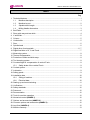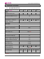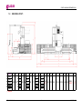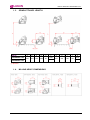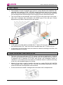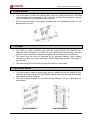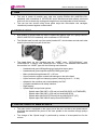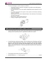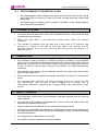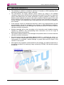
1
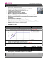
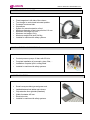
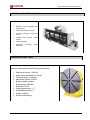
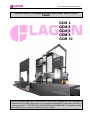
GORATU MAQUINAS HERRAMIENTA,S.A.
TRAVELLING COLUMN MILLING MACHINE WITH FIXED
TABLE
GCM 4
GCM 5
GCM 6
GCM 8
GCM 10
GORATU'S great experience in the machine tool sector, together with the remarkable
competence of the R&D department of its Integral Technological Centre have resulted in
a new generation of TRAVELLING COLUMN MILLING MACHINE of excellent quality,
great performance, accuracy, flexibility and high output.
GORATU MAQUINAS HERRAMIENTA,S.A.
INDEX
Pag.
1. Technical features ..................................................................................................................... 1
1.1.
Machine description ...................................................................................................... 1
1.2.
Machine lay-out ............................................................................................................. 2
1.3.
Spindle travel Length .................................................................................................... 3
1.4.
Milling Head’s dimensions ............................................................................................ 3
2. Bed-Table .................................................................................................................................. 4
3. Rear guide way and rear slide .................................................................................................. 4
4. X axis slide ................................................................................................................................ 5
5. Column...................................................................................................................................... 5
6. Vertical slide .............................................................................................................................. 5
7. Ram ........................................................................................................................................... 6
8. Spindle head ............................................................................................................................. 6
9. Digital drive of main spindle .................................................................................................. 6, 7
10. Digital feed drive of X, Y and Z axis.......................................................................................... 7
11. Measuring system ..................................................................................................................... 8
12. Thermal compensation.............................................................................................................. 8
13. Protection of slides and slide ways ........................................................................................... 8
14. Tool clamping system ............................................................................................................... 8
15. Counterweight for compensation of vertical Z axis................................................................... 8
15.1.
Safety brake of the vertical Z axis................................................................................. 9
16. Coolant system.......................................................................................................................... 9
17. Lubrication ................................................................................................................................. 9
18. Safety guards ............................................................................................................................ 9
19. Installation data ....................................................................................................................... 10
19.1.
Sitting of machine........................................................................................................ 10
19.2.
Electrical data.............................................................................................................. 10
20. Starting up and commissioning............................................................................................... 11
21. Verifications ............................................................................................................................. 11
22. Safety standards ..................................................................................................................... 12
23. Paintwork................................................................................................................................. 12
24. Documentation ........................................................................................................................ 12
25. Tools for machine operation ................................................................................................... 12
26. Numerical control (ANNEX 1)................................................................................................. 12
27. Options and accessories (ANNEX 2) ..................................................................................... 12
28. Common options and accessories (ANNEX 3) ...................................................................... 12
29. Lay-Outs (ANNEX 4)............................................................................................................... 12
30. Machine warranty .................................................................................................................... 13
GCM 4 / 5 / 6 / 8 / 10
JANUARY - 2011
GORATU MAQUINAS HERRAMIENTA,S.A.
1. TECHNICAL FEATURES
1.1.
MACHINE DESCRIPTION:
TRAVELLING COLUMN MILLING
MACHINE LAGUN
GCM 4
GCM 5
GCM 6
GCM 8
GCM 10
5500x1100
6500x1100
7500x1100
9500x1100
11500x1100
8000
10000
TABLE
WORKING SURFACE (mm)
T SLOTS, NUMBER AND WIDTH (mm)
7x22
DISTANCE BETWEEN SLOTS (mm)
160
2
MAXIMUM WEIGHT ON TABLE (Kgs/m )
6000
TRAVERSE
LONGITUDINAL – X AXIS (mm)
4000
5000
6000
CROSS – Y AXIS (mm)
1200
VERTICAL – Z AXIS (mm)
1500/2000*
RAPID FEEDS
LONGITUDINAL – X AXIS (mm/min)
20000
CROSS – Y AXIS (mm/min)
20000
VERTICAL – Z AXIS (mm/min)
20000
SPINDLE (MAIN SPINDLE)
SPINDLE TAPER
ISO 50 DIN 69871/A
-1
SPEED RANGE (min )
3000/4000*
MAIN MOTOR
MAIN MOTOR POWER (kW)
28/34,5
SERVOMOTOR POWER (kW)
5,37
COOLING MOTOR PUMP (kW)
1,1
CENTRAL LUBRICATION PUMP (kW)
0.15
CENTRAL HYDRAULIC UNIT (kW)
0.75
MACHINE ACCURACY
POSITIONING (mm)
A: 0,015
REPEATABILITY (mm)
R: 0,008
MEASUREMENTS
PLANT LAY-OUT (mm)
9565x6616
10565x6616 11565x6616 13565x6616 15565x6616
MACHINE HEIGHT (mm)
3905,5/4815*
WEIGHTS
NET WEIGHT (Kgs)
28000
31000
34000
40000
46000
GROSS WEIGHT WITH SEA PACKING (Kgs)
31000
34000
39000
45000
52000
TOTAL INSTALLED POWER (kW)
54
(*) Optional
GCM 4 / 5 / 6 / 8 / 10
1
JANUARY - 2011
GORATU MAQUINAS HERRAMIENTA,S.A.
1.2.
MACHINE LAYOUT:
LAGUN
A
B
C
D
E
F
G
H
I
J
K
L
M
N
O
P
Q
R
S
T
U
GCM 4
4000
5500
7400
9565
5000
6500
8400
10565
GCM 5
2550
3905,5 -----2000
1175
325
950
950
1175
990
950 1100 692,5 5412,5 1203,5 6616 1400
GCM 6
6000
7500
9400
11565
3050*
4405,5* 4815*
8000
9500
11400
13565
GCM 8
GCM 10
10000
11500
13400
15565
(*) Optional
GCM 4 / 5 / 6 / 8 / 10
2
JANUARY - 2011
GORATU MAQUINAS HERRAMIENTA,S.A.
1.3.
SPINDLE TRAVEL LENGTH
LAGUN
TRAVERSE Z 1500
A
B
C
D
E
533
290
184
1200
62
F
1562
2062*
TRAVERSE Z 2000
G
H
I
J
591
232
126
120
K
1620
2120*
(*) Optional
1.4.
MILLING HEAD´S DIMENSIONS
GCM 4 / 5 / 6 / 8 / 10
3
JANUARY - 2011
GORATU MAQUINAS HERRAMIENTA,S.A.
2. BED-TABLE
§
The bed-table is made of pearlitic grey cast iron, quality EN-GJL-300 (UNE-EN 1561
standard) with hardness of 190 ÷ 220 HB, robustly reinforced with ribs at the bottom
every 500 mm and studied by finite elements. Stabilisation is performed after machining
thus avoiding that the stress during the first roughing process causes deformations.
§
The column slides on the bed-table, with 2 size 55 linear roller guide ways in front and 1
slide with 6 carriages with recirculation rolls (RUSV type) in the rear part. Column
displacement by means of double pinion rack system.
§
In the upper part of the table is provided with 7 T-slots of 22 mm; the central one serves
as a reference with 22 H7. Also in the front of the table there are 2 T-slots of 22 mm
§
In the bottom part of the base holes are located for machine anchoring to the floor, with
threaded supports for leveling.
3. REAR GUIDEWAY AND REAR SLIDE
§
The base of the rear guide way is ST-52 material, with thermal stabilization, reinforced
with ribs, and studied with finite elements. On this base ties a bolted steel way, which it
is hardened with a hardness of 60 HRC and ground, with rectangular section of
140x50mm. In the bottom part of the base are located the holes for machine anchoring
to the floor, with threaded supports for leveling.
§
Material of rear slide is made of pearlitic grey cast iron, quality EN-GJL-300 (UNE-EN
1561 standard), with a hardness of 190 ÷ 220 HB, with thermal stabilization, robustly
reinforced with ribs and subjected to finite elements.
§
On the rear slide are located 6 carriages with recirculation rolls for displacement.
GCM 4 / 5 / 6 / 8 / 10
4
JANUARY - 2011
GORATU MAQUINAS HERRAMIENTA,S.A.
4. X AXIS SLIDE
§
The X-axis slide is made from pearlitic grey cast iron, quality EN-GJL-300 (UNE-EN
1561 standard), with a hardness of 190 ÷ 220 HB, with thermal stabilization, robustly
reinforced with ribs and subjected to finite elements.
§
On the slide are located 6 long guide carriages and two independent motors for the
displacement of X-axis.
5. COLUMN
§
The column is made of pearlitic grey cast iron, quality EN-GJL-300 (UNE-EN 1561
standard), with a hardness of 190-220 HB, and is dimensioned and robustly reinforced
with inner ribs to absorb the cutting and weight forces and studied by finite elements.
§
The column and the bed are separated by an adequate distance, which enables
machining of large voluminous parts with a width greater than the table, and milling of
their rear side.
§
The column has two size-45 rolling linear guide ways for vertical slide.
6. VERTICAL SLIDE
§
The vertical slide is made of pearlitic grey cast iron, quality EN-GJL-300 (UNE-EN 1561
standard), and has a hardness of 190-220HB, robustly reinforced with ribs at the bottom
and subjected to finite elements.
§
There are 8 guide carriages for Z movement and another 6 for the Y movement, as
shown below.
Y AXIS MOVEMENT
GCM 4 / 5 / 6 / 8 / 10
Z AXIS MOVEMENT
5
JANUARY - 2011
GORATU MAQUINAS HERRAMIENTA,S.A.
7. RAM
§
The ram is made of pearlitic grey cast iron, quality EN-GJL-300 (UNE-EN 1561
standard), with a hardness of 190-220 HB, and is dimensioned and robustly reinforced
with inner ribs to absorb the cutting and weight forces and subjected to finite elements.
§
The ram has two size-45 rolling linear guide ways with recirculation rolls carriages,
closed and protected against contamination.
8. SPINDLE HEAD
§
Both bodies of spindle head are made of spheroidal graphite cast iron, quality EN-GJSHB155 (UNE-EN 1563 standard), with a hardness of 130-180 HB.
§
The Spindle head is made up of two parts joined at 45º, which rotates around each other
and are joined to the front part of the ram.
§
The head fitted on the machine can be “HURE” type, “ORTHOGONAL” type,
“HORIZONTAL L 290mm” and “HORIZONTAL L 650mm”. The standard head fitted on
the machine is a “HURE” type with the following main features:
o
o
o
o
o
o
o
o
o
Hardened and ground Klingerlberg-type epicyclical taper gears
Hardened and ground spindle shaft DIN 5480 (gear type).
Main spindle bearing diameter 85 x 130 mm.
Super-precision angular-contact ball bearings on the entire head.
Hydro-mechanic type tool clamping system (clamping force 13 / 16 kN).
Adapted to the machine and commanded by the CNC.
Complete installation with safety interface.
Rigid tapping.
Spindle taper and pull stud options:
- Spindle taper DIN 69871 A/50 and pull stud DIN 69872 A (STANDARD)
- Spindle taper DIN 69871 A/50 and pull stud ANSI B5.50
- Spindle taper MAS 403 BT/50 and pull stud MAS 403 BT (45º)
- Spindle taper DIN 2080/50 and pull stud DIN 69872 A
9. DIGITAL DRIVE OF MAIN SPINDLE
§
The main motor is equipped on the upper part of the ram, and has a two-speed reducer
box fitted that transmits the power to the main spindle to the machine through pulleys
and belts.
§
The change of the “Speed range” is performed by means of a two-speed box for the
motors.
GCM 4 / 5 / 6 / 8 / 10
6
JANUARY - 2011
GORATU MAQUINAS HERRAMIENTA,S.A.
§
The main advantages of use this element is as follows:
o
o
o
o
o
o
o
Separated lubrication systems for the gearbox (oil) and the main shaft (grease).
Avoids noise emission.
No heat transmission from main spindle (insignificant thermal expansion for this
reason).
No vibration transmission from gears of main spindle, and therefore machining
quality is not affected.
High tangential forces can be withstood thanks to the robustness of the bearings
of the box output shaft.
High efficiency degree (greater than 95%).
Change of range through an electroiman.
10. DIGITAL FEED DRIVE OF THE X, Y AND Z AXIS
§
X axis is with double rack pinion system and electrical preload, two independent motors
and high precision planetary reducer, regulated with master-slave system.
§
Y and Z-axis have a ball screw system. The Y-axis ball screw is 50x16mm, and Z-axis
50x12mm, hardened and ground, quality ISO in accordance with DIN 69051 standard,
guided on one end with combined axial-radial bearings (drive side) and preloaded
angular contact bearings on the other end. Transmission for the movement of the Y-Z
motors to the relevant spindles is made through pulleys and belts and a transmission
relation of i=1,5.
§
The brushless servomotors are driven by regulators.
§
RAPID FEEDS IN X – Y – Z AXIS (mm/min) ............................................................ 20.000
GCM 4 / 5 / 6 / 8 / 10
7
JANUARY - 2011
GORATU MAQUINAS HERRAMIENTA,S.A.
11. MEASURING SYSTEM
§
The measuring system uses direct reading linear encoder with an incremental system
with a resolution of 0,001mm.
§
These encoders are provided with a codification system with several reference sources,
which allows a rapid start of the jobs without the need for long displacements of the
axes for reference searches.
12. THERMAL COMPENSATION
§
Thermal expansion compensation on the X / Y / Z -axis, governed by the CNC with two
temperature probes, one on the headstock and the other one on the rear part of the
machine to check environmental temperature.
13. PROTECTION OF SLIDES AND SLIDEWAYS
§
The rear part of the bed-table is protected with bellows manufactured with NOMEX
cloths, which can resist high temperatures. This bellows protect the guide ways, linear
scales, and the rack of X-axis.
§
The front part of cross slide is protected by a metal shutter with a thickness of 5.5mm.
These shutters protect guide ways and ball screw…of the Z-axis.
§
The ball screw of the Y-axis traverse is protected by a metallic telescopic guard.
14. TOOL CLAMPING SYSTEM
§
The tool releasing system operates by means of a hydraulic piston integrated in the
head itself, and driven by a hydraulic unit, which releases and clamps the tool by means
of track tension spring washers.
§
Tool clamping/releasing can be performed by means of an electric pedal so as to be
able to handle the tool more comfortably.
§
These operations can either be performed manually or automatically provided that the
machine is equipped with a tool magazine.
15. COUNTERWEIGHT FOR COMPENSATION OF VERTICAL Z AXIS
§
The Z-axis (vertical slide and ram) is balanced by means of a counterweight
system, made up of a hydraulic cylinder and its rod attached to the vertical
slide, and connected to a nitrogen accumulator, which together form a closed
circuit, so that there is no need for an additional hydraulic unit during
operation.
§
If for any reason, a discharge of the circuit takes place and the pressure drops below the
established limits for a correct operation of the system, a device manually charges the
system again. The instructions to charge manually are detailed in machine maintenance
manual.
§
Nevertheless, the machine is equipped with a safety system, which blocks the operation
of the entire system in case of an emergency.
GCM 4 / 5 / 6 / 8 / 10
8
JANUARY - 2011
GORATU MAQUINAS HERRAMIENTA,S.A.
15.1. SAFETY BRAKE OF THE VERTICAL Z AXIS
o
An electromagnetic brake is fitted on the upper end of the ball screw of the vertical
axis, which acts as a security in case of a power cut and avoids the vertical slide
falling down.
o
This safety system is fitted in case of a failure in operation of the counterweight for
the vertical slide compensation.
16. COOLANT SYSTEM
§
A reservoir has been fitted on the outer end of the bed with a tank, which holds 880 litres
of coolant and a motor pump.
§
Within the tank there is an electrical coolant level switch for coolant
vigilante.
§
The coolant is pumped from the tank with a flow rate of 30 liter/min and
pressure of 4 bars to the end of the main shaft. The nozzles can be
adjusted towards the tool point, and the flow can be set by means of a
shut-off valve.
17. LUBRICATION
§
The lubrication system consists of a central unit which by means of a time delayed
signal given by the CNC automatically distributes the oil to several points such as
ball screws, to the MR type roller shoes in three axis and RUSV type roller shoes of
X axis. In order to have smooth running of the machine, all rolling elements are
lubricated.
§
The lubrication may also be set into operation manually by means of an electric push
button on the control panel.
§
Pinion and racks are lubricated from grease lubrication unit and by a felt greaser
pinion.
§
This unit has been provided with safety systems and circuit control so that
any abnormality, low oil level in tank, clogging up of piping, etc. is
immediately detected, triggering the corresponding alarm displayed on the
screen.
18. SAFETY GUARDS
§
One sliding door, which moves in either direction, has been equipped onto the front part
of the machine.
§
The rear part of the machine is protected with a fence, which has fitted a door with
protected access and safety system.
§
Operator cabinet moves with the column, protected with safety system.
§
All the doors are equipped with windows to visualize the work area. Those windows are
for safety requests of the machine and they are designed to resist an impact according
with machine features.
§
Low-voltage lamp for illumination of work area.
§
For machine control is located an illumination indicator.
GCM 4 / 5 / 6 / 8 / 10
9
JANUARY - 2011
GORATU MAQUINAS HERRAMIENTA,S.A.
19. INSTALLATION DATA
19.1. SITTING OF MACHINE
o
In order to get the most out of your machine, we recommend the following sitting:
- A place with a firm floor.
- Environmental temperature of 22º ± 3
- Maximum relative humidity of air 75%
o
Avoid the following locations:
- Where machine is exposed to direct sunlight and/or any other heat source.
- Places with nearby vibration sources. If he above location can not be
avoided, provide the machine base with an anti-vibrating system.
- Upper floors. If there is no other alternative, make sure it is placed near a
pillar or reinforce the floor with an extra layer of concrete.
o
Provide sufficient free space around the machine to fit accessories, machine
supplements, to carry out repairs, to ensure operator mobility, etc.
19.2. ELECTRICAL DATA
o
In order to connect our regulation equipment for energy return to the net, bear in
mind the following requirements:
- This equipment may be connected directly in case the factory network is of
the TN type. This concerns a symmetric three-phase AC network with 4 or 5
wires with the star connection connected to ground (see fig. A).
- With another type of network, use a separator transformer with the star
connection of the secondary connected to ground (see fig. B).
VOLTAGE...................................................................................... 400 V ± 10 %; 50 Hz ± 1 %
SERVICE VOLTAGE .................................................................... 110 V AC / 24 V DC
LAMP ............................................................................................. Protection IP 67; 220 V
ELECTRIC CABINET .................................................................... Protection IP 55
COOLANT OF ELECTRIC CABINET………………………………Protection int. IP 34/ext. IP 54
GCM 4 / 5 / 6 / 8 / 10
10
JANUARY - 2011
GORATU MAQUINAS HERRAMIENTA,S.A.
20. STARTING UP AND COMMISSIONING
§
Customer request:
o
o
o
Machine sitting following GORATU`s foundation instructions.
Electrical connection following GORATU`s instructions.
Air connection following GORATU`s instructions.
§
Machine visual inspection, in order to check any damage that may occur during
transport.
§
Check properly power supply and air connections (phase order and pressure).
§
Check properly good performance of machine:
o
o
o
o
Movement of all axis.
Spindle rotation / Orientation.
Accessories / Auxiliary equipments.
Gears / Refrigeration
§
Geometrical verification as per UNE standard specified for each type of machine.
§
Operation training:
o
1 Day (8 hours) for basic numerical control operation for standard machine
without options. Training course with following contents:
1.
2.
3.
4.
5.
6.
o
Control panel / CNC.
Axis movement / Reference setting.
Offsets calculation / work piece reference.
Edition / program selection.
Tool offset
Program transmission (PC – CNC).
Options:
1.
2.
3.
4.
5.
Tool measuring probe. (2 hours).
Work piece measuring probe. (3 hours).
Digitalising probe. (6 hours).
Electronic dividing table. (1 hour).
Tool magazine. (1,5 hours).
21. VERIFICATIONS
§
The machine is geometrically verified in accordance with Geometrical verification
standard of GORATU, adaptation of Spanish standard UNE 15-302/90, from ISO 19841982, and compendium of DIN 8615, part 3 and 4 relative to “verification conditions of
fixed bed height milling machine and mandrino in horizontal position and/or mandrino in
vertical”
§
Axis positioning verification is made by laser according to ISO 230-2 standard.
§
POSITIONING ACCURACY (mm)................................................................... A: 0,015 mm
§
REPEATABILITY (mm).................................................................................... R: 0,008 mm
(*) For X>3000 mm traverse, increase 0,005 mm. For each additional 1000 mm.
GCM 4 / 5 / 6 / 8 / 10
11
JANUARY - 2011
GORATU MAQUINAS HERRAMIENTA,S.A.
22. SAFETY STANDARDS
§
The machine has been designed and constructed in accordance with:
o
o
o
o
Machinery directive 2006/42/CE
Electromagnetic Compatibility Directive 2004/108/CE
Low tension Electrical Facilities Directive 2006/95/CE
Safety standards on machining centres EN 12417+A2
23. PAINTWORK
§
§
§
Machine and splashguard light dark texturized RAL 7466 and light grey.
Doors, headstock, CNC desk, dark grey texturized RAL 7466.
Accessories in dark grey texturized RAL 7466.
24. DOCUMENTATION
§
§
§
§
1 Complete machine manual, with assembly drawings and part lists.
1 set of CNC manuals.
Machine parameters.
Verification record.
25. TOOLS FOR MACHINE OPERATION
§
§
§
§
§
Sling pack.
Draw bars for tools according to machine taper.
Double-end spanner 30-32 to perform manual headstock.
Fix key size 46 for machine levelling.
Samoa lubrication pump to lubricate headstock gears.
26. NUMERICAL CONTROL
v SEE ANNEX 1
27. OPTIONS AND ACCESSORIES
v SEE ANNEX 2
28. LAY – OUTS
v SEE ANNEX 3
GCM 4 / 5 / 6 / 8 / 10
12
JANUARY - 2011
GORATU MAQUINAS HERRAMIENTA,S.A.
29.
MACHINE WARRANTY
§
This warranty is valid for a maximum period of 12 months or 2000 operating hours
(whichever first) based upon an 8 hour a day shift.
§
The manufacturer will supply defective pieces without any charge in EX WORKS
conditions; repair carried out during the warranty period and will not serve to extent this
period. Renovated pieces will remain warranted in original conditions of machine. Any
defective parts replaced will remain at the seller’s disposal. Defective parts will be send
by the customer to the manufacturer, once the customer have received his spare parts.
On the contrary, if the customers don’t send spare parts, the invoice will be charged to
the customer.
§
If the customer require of manufacture technician, labour cost, displacements cost and
accommodation cost will be charged to the customer, in AFM established conditions.
Machine warranty doesn’t cover damages and operation failures of incorrect machine
utilization and their accessories.
§
Machine assembly will be done according to the instructions and foundation drawing
supplied by GORATU. Not accomplishing these instructions can be the origin of
geometrical tolerances deviations.
§
The machine warranty doesn’t cover damages and operation failure of incorrect machine
utilization and their accessories.
§
We recommend read the instructions Manual carefully, in particular the section on
SAFETY. GORATU MAQUINAS HERRAMIENTA S.A. is under no obligation to pay any
compensation for accidents, material damage to goods other than the object of the
contract or loss of profit.
§
With regard to the regulation of that specified in this warranty, the parties should refer to
the general conditions for machinery supply outlined by CECIMO, with which the parties
are familiar.
www.goratu.com
GORATU MAQUINAS HERRAMIENTA, S.A.
Lerun,1 Apdo/P.O. Box 39 - E-20870 Elgoibar - Guipúzcoa - SPAIN
Tel.: +34 943 748 262 - Fax: +34 943 744 323 / 093
e-mail: [email protected]
GCM 4 / 5 / 6 / 8 / 10
13
JANUARY - 2011
GORATU MAQUINAS HERRAMIENTA,S.A.
(STANDARD ACCESSORIES)
NUMERICAL CONTROL
GCM 4 / 5 / 6 / 8 / 10
14
JANUARY - 2011
GORATU MAQUINAS HERRAMIENTA,S.A.
- CNC SIEMENS 840 D
l
§
§
§
§
§
§
§
§
§
§
§
§
§
§
§
l
STANDARD USER FUNCTIONS
Conversational programming language Shop Turn and DIN/ISO.
NCU 571.5: Permits up to 6 axes and 6 heads.
Operator panel OP32S with Colour screen LCD 10,4”.
Complete alphanumeric keyboard.
Speed of communication device 1,5 Mbauds.
Memory of 6 Mbytes for work piece programmes.
Ethernet connections and serial RS 232-C.
Software MCIS DNC Machine for transmission programmes through Ethernet.
PCU 50 hard disk 40GB /15 GB for user (LOCAL BACKUPS AND SOFTWARE TO BE INSTALLED).
Machining cycle’s characteristic of milling machines through dialogue-based
programming.
Possibility of screen customisation.
Teleservice through MODEM (phone line) or Ethernet.
Diagnosis: Interconnection signals, NC alarms, PLC alarms…
Backlash compensation, error of quadrant change, tool correction and RTCP tool
orientation.
Machine-operators interface in Russian language
SIEMENS MOTORS
SIEMENS MAIN MOTOR
MODEL
TORQUE (Nm)
POWER (kW)
1PH7 167-2ND23-0BC2
267
28
POWER AND TORQUE DIAGRAM FOR 3000 RPM / 4000 RPM
Two operation modes may be deduced from the power diagram:
• Constant torque [1068/1316 Nm] at speed of 0÷250 min-¹
• Constant power [28/34,5 kW] at speed of 251÷3000 min-¹ / 4000 min-¹
The horizontal line shows the working zone at constant power, i.e. the total power of the main motor may be
used [28/34,5 kW]. The slanted lines show the constant torque zone in which the power is proportionally
reduced as the speed decreases. Hence, using speeds lower than 250 min-1, motor progressively decreases.
MODEL
X AXIS SIEMENS SERVOMOTOR 1FK7 103-5AF71-1AH0(with brake)
Y AXIS SIEMENS SERVOMOTOR
1FK7 103-5AF71-1AG0
Z AXIS SIEMENS SERVOMOTOR
1FK7 103-5AF71-1AG0
l
TORQUE (Nm)
POWER (kW)
36
36
36
5,37
5,37
5,37
AXIAL FORCE OR PUSHING FORCE OF X, Y, Z AXES
X Axis – Pinion-Rack (N).................................................................................................... 31140,43
Y Axis – Ball screw (N)....................................................................................................... 13901,58
Z Axis – Ball screw (N)....................................................................................................... 18535,44
GCM 4 / 5 / 6 / 8 / 10
15
JANUARY - 2011
GORATU MAQUINAS HERRAMIENTA,S.A.
l
§
§
§
OPERATOR PANEL IN FRONT OF BED-TABLE
Possibility to install all CNC-s.
Installed on guide ways, it can be moved in all bed table
traverses.
Installed in machine with safety systems.
GCM 4 / 5 / 6 / 8 / 10
16
JANUARY - 2011
GORATU MAQUINAS HERRAMIENTA,S.A.
OPTIONAL ACCESSORIES
GCM 4 / 5 / 6 / 8 / 10
17
JANUARY - 2011
GORATU MAQUINAS HERRAMIENTA,S.A.
1. AUTOMATIC TOOL CHANGER
§
§
§
§
§
§
§
§
§
§
Fixed magazine in left side of the column.
Tool change in vertical and horizontal position.
Protected in external side.
24 positions
System for manual extraction of tool.
Maximum diameter of tool using all slots 110 mm.
Maximum tool length 350 mm.
Maximum tool weight 15 Kg.
Maximum weight of all tools 240 Kg.
Installed in machine with safety systems
2. COOLANT THROUGH THE SPINDLE
§
Coolant pressure pumps 10 bars with 35 l/min.
§
Complete installation of pneumatic, pipes, filter, ...
§
Installation of special joint in milling head.
Installed in machine with safety systems.
§
3. SWARF CONVEYOR
§
Swarf conveyors chain type and goose neck
§
§
§
Installed between bed-tables and columns.
Chip extraction from right side (Standard).
Width of extractor 400 mm.
Electrical motor.
Installed in machine with safety systems.
§
§
GCM 4 / 5 / 6 / 8 / 10
18
JANUARY - 2011
GORATU MAQUINAS HERRAMIENTA,S.A.
4. FRONTAL AND LATERAL GUARING
•
Machine frontal guarding with
sliding doors.
•
Lateral and frontal windows
•
6 metres opening of the frontal
doors
•
Installed with security safety
system
•
Lateral guarding
•
Enclosure
standards
according
safety
5. INDEXING ROTARY TABLE
Electronic rotary table with the following main features:
§
§
§
§
§
§
§
§
§
§
§
Diameter of the disc: 1.000 mm
Allowed load with tailstock: 3.500 Kg
Tangential torque: 15000 Nm
Max rotation Speed: 15 RPM
Braking system: hydraulic
Braking torque: 8000 Nm
Resolution: 0,001º
Positioning accuracy: +- 5”
Repeatibility accuracy: 3”
Weight: 2.000 Kg
Dc servomotor driving
GCM 4 / 5 / 6 / 8 / 10
19
JANUARY - 2011
GORATU MAQUINAS HERRAMIENTA,S.A.
6.GHT 6 QUILL & TAILSTOCK
§
§
§
§
§
§
Tailstock with preparation of the quill for chuck
Adaption of the base for the milling machine table
Adapter taper
Manual clamping of the table
Guided on grinded “T” slots of the table
Manual blocking
7. HYDRAULIC CLAMPING CHUCK
§
§
§
§
§
§
§
§
Hydraulic work piece clamping system
Hydraulic chuck SMW IND 1.000 mm with blind hole
Clamping diameter: 1.000 mm
Hydraulic cylinder
Connection draw bar
Pedal driven
1 set of soft jaws
Complete installation with safety interface
8. OPENED FIXED STADY REST 580 – 1.000 MM CAPACITY
Opened fixed steady rest with the following main
features:
§
§
§
§
§
Capacity: 580 – 1.000 mm
Manual diameter adjustment
2 points nylon rollers
Load capacity: 4.000 Kg
Cast iron body
GCM 4 / 5 / 6 / 8 / 10
20
JANUARY - 2011
GORATU MAQUINAS HERRAMIENTA,S.A.
9. MANUAL 3 JAWS UNIVERSAL STEEL BODY CHUCK
3 Jaws self-centring chuck with the following main features:
§
§
§
§
§
§
§
Clamping diameter 800 mm
Min clamping diameter: 125mm
Gripping force: 12.300 DaN
Solid reversible jaws
Steel body
Max Speed: 764rpm
10. “JUMA” FILTERING UNIT WITH TANK
§
§
§
§
§
GAIN model of magnetic roller is mounted on the JUMA
model of paper filter, the great advantage of this model is
that the coolant liquid first of all goes through magnetic
divider which eliminate the greater percentage of
particles, next it is going through the paper filter. Used
and contaminated paper filter is collected in an
independent drawer of deposit.
Filtration capacity of 150 l/min.
Coolant deposit of 480 l.
Complete installation of pipes ...
Installed in machine with safety systems.
11. RENISHAW RMP 60 PART TOUCH PROBE
§
§
§
Compatible with all CNC-s.
Signal transmission from RADIO through antenna and
interface.
Software + cable + connector.
GCM 4 / 5 / 6 / 8 / 10
21
JANUARY - 2011
GORATU MAQUINAS HERRAMIENTA,S.A.
12. RENISHAW TS 27 TOOL TOUCH PROBE
§
§
§
Tool measuring probe transmit a commutation signal to the CNC once
the tool measuring probe is bended from the rest position of tool.
Compatible with all CNC-s.
Software + cable + connector.
GCM 4 / 5 / 6 / 8 / 10
22
JANUARY - 2011