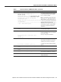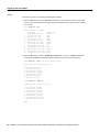
1
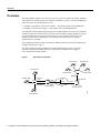
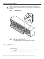
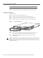
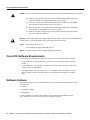
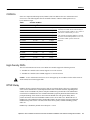
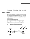
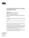
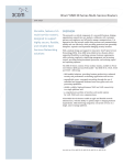
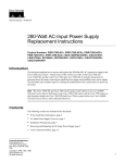
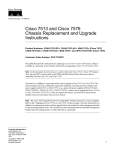
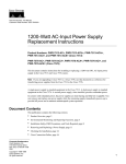
Text Part Number: 78-6271-01
Updates to Cisco AS5300 Universal
Access Server Module Installation and
Software Configuration Guides
Product Number: DOC-785891=, DOC-AS5300SWG=
This document includes updated information for DSP modules on the Voice-over-IP (VoIP) card for
the Cisco AS5300 Universal Access Server Module Installation Guide and the Cisco AS5300
Universal Access Server Software Configuration Guide. This document includes the following
sections:
•
•
•
•
•
•
•
•
•
•
•
Overview, page 2
Hardware Features, page 3
Safety Recommendations, page 4
Required Tools and Equipment, page 8
Removing and Installing Cards and Modules, page 8
Cisco IOS Software Requirements, page 14
Software Features, page 14
Preparing to Configure the Software, page 17
Upgrading VoIP Card VCWare, page 18
Cisco Connection Online, page 25
Documentation CD-ROM, page 26
Corporate Headquarters
Cisco Systems, Inc.
170 West Tasman Drive
San Jose, CA 95134-1706
USA
Copyright © 1999
Cisco Systems, Inc.
All rights reserved.
1
Overview
Overview
The VoIP capability enables a Cisco access server to carry live voice traffic (for example, telephone
calls and faxes) over an IP network. The VoIP card is available as a spare or a factory-installed card
within the chassis. Use this document if you are:
•
•
Installing or upgrading 6 session voice modules — Part Number AS53-6VOX (DSPM 542)
Installing 12 session voice modules — Part Number AS53-VOXD (DSPM 549)
The VoIP card contains multiple digital signal processor (DSP) modules. It uses the Cisco AS5300’s
interface and local-area network (LAN) or wide-area network (WAN) routing capabilities to provide
up to 48/60 channels per Cisco AS5300 universal access server using the AS53-6VOX voice
modules, and up to 96/120 channels per Cisco AS5300 universal access server using the
AS53-VOXD voice modules.
If you purchased a chassis with this card already installed, go directly to the section “Preparing to
Configure the Software,” page 17.
The VoIP card has two primary applications. The first application (see Figure 1) provides a
central-site telephony termination facility for VoIP traffic from multiple voice-equipped
Cisco AS5300 remote office facilities.
Figure 1
VoIP Card as Central Site
729 555-1001
729 555-1002
408 555-1001
729 555-1000
729 555-1003
T1
ISDN PRI
Voice port
0:D
1:D
T1 ISDN PRI
WAN
10.1.1.1
Cisco AS5300
Access Server 1
IP
cloud
Voice port 0:D
WAN
10.1.1.2
Cisco AS5300
Access Server 2
408 555-1003
2 Updates to Cisco AS5300 Universal Access Server Module Installation and Software Configuration Guides
18198
408 555-1002
Hardware Features
The second application (see Figure 2) uses the VoIP card as a PSTN gateway for Internet telephone
traffic. This leverages the standardized use of H.323-based Internet telephone client applications.
Figure 2
VoIP Card as Internet Telephone to PSTN Gateway
408 526-4000
408 526-4001
408 526-4002
PSTN
408 526-4003
310 520-1001
310 520-1002
Central
office
310 520-1000
310 520-1003
Voice port
1/0/0
Cisco AS5300
10.1.1.1
10.1.1.2
Cisco 3640
10352
IP
cloud
Note In certain countries, use of these products or provision of voice telephony over the Internet
may be prohibited and/or subject to laws, regulations or licenses, including requirements applicable
to the use of the products under telecommunications and other laws and regulations; customer must
comply with all such applicable laws in the country(ies) where customer intends to use the product.
Hardware Features
This section describes the basic hardware features of the VoIP card and the DSP modules, which are
listed below:
•
•
VoIP Card
DSP Modules
Note You need 16 MB of system Flash memory to store two Cisco IOS images on your
Cisco AS5300 access server.
Updates to Cisco AS5300 Universal Access Server Module Installation and Software Configuration Guides
3
Safety Recommendations
VoIP Card
The VoIP card resides in one of the slots in the Cisco AS5300 universal access server. Up to five DSP
modules can be installed onto the voice card to perform voice processing for up to 30 B channels for
single-density DSPs and 60 B channels for double-density DSPs.
•
•
•
•
•
CPU: MIPS 4700 100 MHz
Support chipset: GT-64010 system controller
DRAM: Standard 72 pin SIMM (4, 8, 16 MB)
Flash memory: Cisco proprietary Flash 80 pin SIMM
Five DSP module sockets
DSP Modules
The DSP module provides voice compression and packetization services to the voice card so that
you can both configure and expand it.
•
Six DSPs per DSP module, use four DSP modules for T1 applications and five DSP modules for
E1 applications
•
•
Uses TI TMS320C542 50 MHz or TI TMS320C549 100 MHz
DSP SRAM: 128 Kwords (16 bit)
Do not mix DSP modules on the same voice card. You cannot install a DSP 549 double-density
module and a DSP 542 module on the same voice card, nor can you mix a voice card carrying only DSP 549
modules and a voice card carrying only DSP 542 modules in the same chassis.
Caution
Safety Recommendations
This section describes the safety warnings and recommendations you must take into consideration
when working on voice card DSP modules for the Cisco AS5300 universal access server. This
section includes the following topics:
•
•
•
•
Safety Warnings
Safety with Electricity
Preventing Electrostatic Discharge Damage
General Safety Recommendations
Safety Warnings
Safety warnings appear throughout this document in procedures that, if performed incorrectly, may
harm you. A warning symbol precedes each safety warning.
Warning This warning symbol means danger. You are in a situation that could cause bodily injury.
Before you work on any equipment, be aware of the hazards involved with electrical circuitry and
be familiar with standard practices for preventing accidents. To see translations of the warnings that
appear in this publication, refer to the Regulatory Compliance and Safety Information document that
accompanied this device.
4 Updates to Cisco AS5300 Universal Access Server Module Installation and Software Configuration Guides
Safety Warnings
Waarschuwing Dit waarschuwingssymbool betekent gevaar. U verkeert in een situatie die
lichamelijk letsel kan veroorzaken. Voordat u aan enige apparatuur gaat werken, dient u zich bewust
te zijn van de bij elektrische schakelingen betrokken risico's en dient u op de hoogte te zijn van
standaard maatregelen om ongelukken te voorkomen. Voor vertalingen van de waarschuwingen die
in deze publicatie verschijnen, kunt u het document Regulatory Compliance and Safety Information
(Informatie over naleving van veiligheids- en andere voorschriften) raadplegen dat bij dit toestel is
ingesloten.
Varoitus Tämä varoitusmerkki merkitsee vaaraa. Olet tilanteessa, joka voi johtaa ruumiinvammaan.
Ennen kuin työskentelet minkään laitteiston parissa, ota selvää sähkökytkentöihin liittyvistä
vaaroista ja tavanomaisista onnettomuuksien ehkäisykeinoista. Tässä julkaisussa esiintyvien
varoitusten käännökset löydät laitteen mukana olevasta Regulatory Compliance and Safety
Information -kirjasesta (määräysten noudattaminen ja tietoa turvallisuudesta).
Attention Ce symbole d'avertissement indique un danger. Vous vous trouvez dans une situation
pouvant causer des blessures ou des dommages corporels. Avant de travailler sur un équipement,
soyez conscient des dangers posés par les circuits électriques et familiarisez-vous avec les
procédures couramment utilisées pour éviter les accidents. Pour prendre connaissance des
traductions d’avertissements figurant dans cette publication, consultez le document Regulatory
Compliance and Safety Information (Conformité aux règlements et consignes de sécurité) qui
accompagne cet appareil.
Warnung Dieses Warnsymbol bedeutet Gefahr. Sie befinden sich in einer Situation, die zu einer
Körperverletzung führen könnte. Bevor Sie mit der Arbeit an irgendeinem Gerät beginnen, seien Sie
sich der mit elektrischen Stromkreisen verbundenen Gefahren und der Standardpraktiken zur
Vermeidung von Unfällen bewußt. Übersetzungen der in dieser Veröffentlichung enthaltenen
Warnhinweise finden Sie im Dokument Regulatory Compliance and Safety Information
(Informationen zu behördlichen Vorschriften und Sicherheit), das zusammen mit diesem Gerät
geliefert wurde.
Avvertenza Questo simbolo di avvertenza indica un pericolo. La situazione potrebbe causare
infortuni alle persone. Prima di lavorare su qualsiasi apparecchiatura, occorre conoscere i pericoli
relativi ai circuiti elettrici ed essere al corrente delle pratiche standard per la prevenzione di incidenti.
La traduzione delle avvertenze riportate in questa pubblicazione si trova nel documento Regulatory
Compliance and Safety Information (Conformità alle norme e informazioni sulla sicurezza) che
accompagna questo dispositivo.
Advarsel Dette varselsymbolet betyr fare. Du befinner deg i en situasjon som kan føre til
personskade. Før du utfører arbeid på utstyr, må du vare oppmerksom på de faremomentene som
elektriske kretser innebærer, samt gjøre deg kjent med vanlig praksis når det gjelder å unngå ulykker.
Hvis du vil se oversettelser av de advarslene som finnes i denne publikasjonen, kan du se i
dokumentet Regulatory Compliance and Safety Information (Overholdelse av forskrifter og
sikkerhetsinformasjon) som ble levert med denne enheten.
Aviso Este símbolo de aviso indica perigo. Encontra-se numa situação que lhe poderá causar danos
físicos. Antes de começar a trabalhar com qualquer equipamento, familiarize-se com os perigos
relacionados com circuitos eléctricos, e com quaisquer práticas comuns que possam prevenir
possíveis acidentes. Para ver as traduções dos avisos que constam desta publicação, consulte o
documento Regulatory Compliance and Safety Information (Informação de Segurança e
Disposições Reguladoras) que acompanha este dispositivo.
¡Advertencia! Este símbolo de aviso significa peligro. Existe riesgo para su integridad física. Antes
de manipular cualquier equipo, considerar los riesgos que entraña la corriente eléctrica y
familiarizarse con los procedimientos estándar de prevención de accidentes. Para ver una traducción
de las advertencias que aparecen en esta publicación, consultar el documento titulado Regulatory
Compliance and Safety Information (Información sobre seguridad y conformidad con las
disposiciones reglamentarias) que se acompaña con este dispositivo.
Updates to Cisco AS5300 Universal Access Server Module Installation and Software Configuration Guides
5
Safety Recommendations
Varning! Denna varningssymbol signalerar fara. Du befinner dig i en situation som kan leda till
personskada. Innan du utför arbete på någon utrustning måste du vara medveten om farorna med
elkretsar och känna till vanligt förfarande för att förebygga skador. Se förklaringar av de varningar
som förkommer i denna publikation i dokumentet Regulatory Compliance and Safety Information
(Efterrättelse av föreskrifter och säkerhetsinformation), vilket medföljer denna anordning.
Safety with Electricity
Warning Read the installation instructions before you connect the system to its power source.
Warning Ultimate disposal of this product should be handled according to all national laws and regulations.
Warning Before working on a chassis or working near power supplies, unplug the power cord on
AC units; disconnect the power at the circuit breaker on DC units.
Warning To ensure your safety and the safety of others, be sure the power is OFF and the power cord is
unplugged before working on the router.
Warning Before working on equipment that is connected to power lines, remove jewelry (including rings,
necklaces, and watches). Metal objects will heat up when connected to power and ground and can cause
serious burns or weld the metal object to the terminals.
Warning Before opening the chassis, disconnect the telephone-network cables to avoid contact with
telephone-network voltages.
Warning
Do not work on the system or connect or disconnect cables during periods of lightning activity.
Warning Do not touch the power supply when the power cord is connected. For systems with a power
switch, line voltages are present within the power supply even when the power switch is off and the power
cord is connected. For systems without a power switch, line voltages are present within the power supply
when the power cord is connected.
Warning Before performing any procedures involving installing or removing chassis elements, ensure that
power is removed from the DC circuit. To ensure that all power is OFF, locate the circuit breaker on the panel
board that services the DC circuit, switch the circuit breaker to the OFF position, and tape the switch handle
of the circuit breaker in the OFF position.
Warning Before working on a chassis or working near power supplies, unplug the power cord on AC units;
disconnect the power at the circuit breaker on DC units.
Warning Before working on equipment that is connected to power lines, remove jewelry (including rings,
necklaces, and watches). Metal objects will heat up when connected to power and ground and can cause
serious burns or weld the metal object to the terminals.
Warning Only trained and qualified service personnel should be allowed to install or replace this equipment.
6 Updates to Cisco AS5300 Universal Access Server Module Installation and Software Configuration Guides
Preventing Electrostatic Discharge Damage
Caution Before opening the chassis, ensure that you have discharged all static electricity from your body
and be sure that the power is OFF.
Follow these guidelines when working on equipment powered by electricity:
•
Locate the emergency power-OFF switch in the room in which you are working. Then, if an
electrical accident occurs, you can quickly shut the power OFF.
•
Disconnect all power before doing the following:
— Installing or removing a chassis
— Working near power supplies
•
•
•
Do not work alone if potentially hazardous conditions exist.
•
If an electrical accident occurs, proceed as follows:
Never assume that power is disconnected from a circuit. Always check.
Look carefully for possible hazards in your work area, such as moist floors, ungrounded power
extension cables, and missing safety grounds.
— Use caution; do not become a victim yourself.
— Turn OFF power to the system.
— If possible, send another person to get medical aid. Otherwise, determine the condition of the
victim and then call for help.
— Determine if the person needs rescue breathing or external cardiac compressions; then take
appropriate action.
Preventing Electrostatic Discharge Damage
Electrostatic discharge (ESD) can damage equipment and impair electrical circuitry. It occurs when
electronic printed circuit cards are improperly handled and can result in complete or intermittent
failures. Always follow ESD prevention procedures when removing and replacing cards. Ensure that
the chassis is electrically connected to earth ground. Wear an ESD-preventive wrist strap, ensuring
that it makes good skin contact. Connect the clip to an unpainted surface of the chassis frame to
safely channel unwanted ESD voltages to ground. To properly guard against ESD damage and
shocks, the wrist strap and cord must operate effectively. If no wrist strap is available, ground
yourself by touching the metal part of the chassis.
For safety, periodically check the resistance value of the antistatic strap, which should be between
1 and 10 megohm (Mohm).
Caution
General Safety Recommendations
Follow these guidelines to ensure general safety:
•
•
•
•
Keep the chassis area clear and dust-free during and after installation.
Put the removed chassis cover in a safe place.
Keep tools away from walk areas where you or others could fall over them.
Do not wear loose clothing that could get caught in the chassis. Fasten your tie or scarf and roll
up your sleeves.
Updates to Cisco AS5300 Universal Access Server Module Installation and Software Configuration Guides
7
Required Tools and Equipment
•
•
Wear safety glasses when working under any conditions that might be hazardous to your eyes.
Do not perform any action that creates a potential hazard to people or makes the equipment
unsafe.
Required Tools and Equipment
To install or remove voice cards with DSP modules or perform other maintenance procedures, you
will need the following tools and equipment, which are not included:
•
•
•
•
•
•
•
Cisco AS5300 universal access server
Card removal tool
Medium-size Phillips screwdriver
ESD-preventive wrist strap
ESD-preventive mat
Antistatic bag (optional)
Blank slot covers for open slots
Removing and Installing Cards and Modules
This section describes how to remove and install VoIP cards and modules. This section describes
how to:
•
•
•
•
Removing VoIP Cards
Removing DSP Modules
Installing DSP Modules
Installing VoIP Cards
Removing VoIP Cards
If you are installing (rather than replacing) a card, skip this topic.
To remove the VoIP card, perform the following steps:
Step 1
Attach an ESD-preventive wrist strap.
Warning Do not work on the system or connect or disconnect cables during periods of lightning activity.
The cards are not hot-swappable (that is, you cannot remove or install them when the power to the
access server is ON). Be sure to turn OFF the power to the access server before installing or removing cards.
Failure to do so can damage the access server.
Caution
Step 2
Power OFF the access server. Turn the power switch on the access server OFF and
disconnect site power. If using a DC-powered unit, read the warning that follows, then
refer to Figure 3 and complete steps a to d.
8 Updates to Cisco AS5300 Universal Access Server Module Installation and Software Configuration Guides
Removing VoIP Cards
Warning Before performing any of the following procedures, ensure that power is removed from the DC
circuit. To ensure that all power is OFF, locate the circuit breaker on the panel board that services the DC
circuit, switch the circuit breaker to the OFF position, and tape the switch handle of the circuit breaker in the
OFF position.
Figure 3
DC Power Supply Connections
Mounting screw
Mounting screw
Terminal
block
H10720
On/off
switch
Mounting screw
Strain-relief
clamp
(a)
Loosen the three locking screws for the negative, positive, and ground connectors
on the DC power supply terminal block.
(b)
Remove the -48 VDC wire from the terminal block negative connector (-) .
(c)
Remove the +48 VDC wire from the terminal block positive connector (+) .
(d)
Remove the safety ground (green wire) from the terminal block ground connector.
Step 3
On the rear panel of the access server, locate the VoIP card seen in Figure 4.
Step 4
Loosen the two captive screws that secure the VoIP card to the chassis until each screw is
free of the chassis. (See Figure 4.)
VoIP Card Removal
H11139
Figure 4
Captive screws
Step 5
Insert the card removal tool so that the slots in each arm of the tool are behind the shoulder
of each captive screw, as shown in Figure 5, and carefully pull the removal tool toward
you until the VoIP card slides free of the chassis.
Updates to Cisco AS5300 Universal Access Server Module Installation and Software Configuration Guides
9
Removing and Installing Cards and Modules
Caution The EMI protective devices on the VoIP card are designed to make the card fit tightly. When
removing the card, they can release suddenly. Exercise caution when removing the VoIP card with the card
removal tool.
Figure 5
Removing VoIP Card
PO
RT
SE
LE
CT
LB
RA
LA
A
0
SA
1
S
A
2
SA
3
S
A
4
SA
5
SA
6
S
A
7
S
T1
T0
T3
T2
AC
T
OK
RX
14834
TX
Step 6
Set the removed VoIP card aside on an ESD-preventive mat.
Step 7
Continue with one of the following sections:
•
•
“Removing DSP Modules” to remove DSP modules from the VoIP card.
“Installing VoIP Cards” to install a new VoIP card.
Removing DSP Modules
If you are installing a new card with modules already mounted on it, go directly to the topic,
“Installing VoIP Cards.”
To remove DSP modules:
Step 1
Make sure that you have attached an ESD-preventive wrist strap and that the system is
powered OFF.
Step 2
On the VoIP card, locate the DSP module you will replace (see Figure 6).
10 Updates to Cisco AS5300 Universal Access Server Module Installation and Software Configuration Guides
Installing DSP Modules
Removing DSP Modules
H11140
Figure 6
Step 3
Orient the VoIP card so that the DSP module socket is facing toward you.
Step 4
Gently pry the front edge of the DSP module away from the standoffs and the socket,
as indicated by the arrow labeled 1 in Figure 6.
Step 5
When the DSP module is free of the socket, gently pry the back edge of the DSP module
away from the other set of standoffs, as indicated by the arrow labeled 2 in Figure 6.
Installing DSP Modules
If you are installing a new card with modules already mounted on it, go directly to the topic,
“Installing VoIP Cards.”
Do not mix DSP modules on the same voice card. You cannot install a DSP 549 double-density
module and a DSP 542 module on the same voice card, nor can you mix a voice card carrying only DSP 549
modules and a voice card carrying only DSP 542 modules in the same chassis.
Caution
To install a DSP module:
Step 1
Seat the DSP module in the socket.
Step 2
Press all four corners onto their respective standoffs, as shown in Figure 7.
Installing DSP Modules
H11141
Figure 7
Updates to Cisco AS5300 Universal Access Server Module Installation and Software Configuration Guides
11
Removing and Installing Cards and Modules
Note Mate the socket on the DSP module with the socket on the VoIP card.
Step 3
Continue with the following section, “Installing VoIP Cards” to install the VoIP card.
Installing VoIP Cards
To install a VoIP card:
Step 1
Remove the VoIP card from the ESD-preventive mat.
Step 2
Slide the VoIP card into the slot until it touches the backplane connector.
Step 3
Align the captive screws with their holes, and then seat the VoIP card completely.
Step 4
Tighten the two captive screws (see Figure 8) to secure the VoIP card to the chassis.
Installing the VoIP Card
H11139
Figure 8
Captive screws
Step 5
If the access server is configured with fewer than three cards, make sure that a blank slot
cover is installed over each open slot to ensure proper airflow inside the chassis.
Step 6
Reconnect the AC power cord. Or, if using DC power, refer to Figure 9, and then
complete steps a to d.
Caution The illustration shows the DC power supply terminal block. Wire the DC power supply using the
appropriate wire terminations at the wiring end, as illustrated. The proper wiring sequence is ground to
ground, positive to positive, and negative to negative. Note that the ground wire should always be connected
first and disconnected last.
12 Updates to Cisco AS5300 Universal Access Server Module Installation and Software Configuration Guides
Installing VoIP Cards
Figure 9
DC Power Supply Connections
Terminal
block
H10720
On/off
switch
Mounting screw
Strain-relief
clamp
Updates to Cisco AS5300 Universal Access Server Module Installation and Software Configuration Guides
13
Cisco IOS Software Requirements
Caution Do not overtorque the terminal block contact screws. The recommended torque is 8.2 ± 0.4 inch-lb.
(a)
Insert the safety ground (green wire) into the terminal block ground connector and
tighten the locking screw. Ensure that no bare wire is exposed.
(b)
Insert the +48 VDC wire into the terminal block positive connector (+) and tighten
the locking screw. Ensure that no bare wire is exposed.
(c)
Insert the -48 VDC wire into the terminal block negative connector (-) and tighten
the locking screw. Ensure that no bare wire is exposed.
(d)
Make sure the power supply cord is secured to the cable strain-relief clamps on the
DC power supply with cable ties.
Warning After wiring the DC power supply, remove the tape from the circuit breaker switch handle and
reinstate power by moving the handle of the circuit breaker to the ON position.
Step 7
Power ON the access server.
The internal power supply fan should power on.
Step 8
Continue with the section, “Upgrading VoIP Card VCWare.”
Cisco IOS Software Requirements
The following Cisco IOS Release images are required for the 542 DSP and 549 DSP modules:
•
Cisco IOS Release 12.0(3)XH and 12.0(5)T or later for VoIP-only features on the 542 DSP
module.
•
Cisco IOS Release 12.0(2)XH and 12.0(3)XH, and 12.0(5)T or later for double-density VoIP
features on the 549 DSP modules.
•
VFC ROM monitor software version 1.2 or 1.3 is compatible with your installed Cisco IOS
image. VCWare version 4.0 (or later) requires Cisco IOS Release 12.0(2)XH, 12.0(5)TPI, or
later.
Software Features
This section describes the newest software features of the VoIP card and the DSP modules, which
are listed below:
•
•
•
CODECs
High-Density DSPs
DTMF-Relay
For full descriptions of existing software features of the VoIP card and the DSP refer to the
Cisco AS5300 Universal Access Server Software Configuration Guide.
14 Updates to Cisco AS5300 Universal Access Server Module Installation and Software Configuration Guides
CODECs
CODECs
Some new compression/decompression (CODECs) has been added to the Cisco AS5300 universal
access server. The following table lists the available CODECs with their default packet size (in
bytes) and their ranges.
Table 1
Available CODECs
CODECs
Range1
Default
Bit Rate
G.711ulaw
40 - 240
160
64 Kbps
G.711alaw
40 - 240
160
64 Kbps
G.723r63
24 - 240
24
6.3 Kbps
G.723r53
20 - 240
20
5.3 Kbps
G.723ar63
24 - 240
24
6.3 Kbps
G.723ar53
20 - 240
20
5.3 Kbps
G.726r32
20 - 240
40
32 Kbps
G.726r24
15 - 240
30
24 Kbps
G.726r16
10 - 240
20
16 Kbps
G.728
10 - 240
10
16 Kbps
G.729br8
10 - 240
20
8 Kbps
G.729r8 pre-ietf
10 - 240
20
8 Kbps
G.729r8
10 - 240
20
8 Kbps
1
Comments
A separate CODEC for G.729 Annex B is
included, which adds Annex B functionality to
G.729 and a separate CODEC G.723.1 Annex A
adds Annex A functionality to G.723.1.
The Annex B functionality added to G.729 and
the Annex A functionality added to G.723.1 are
the in-built CODEC specific VAD/CNG
functions.
The Range and Default figures refer to packet sizes in bytes.
High-Density DSPs
The Cisco AS5300 universal access server DSP/voice modules support the following sessions:
•
•
542 DSP/voice module (AS53-6VOX) supports 6 voice/fax sessions.
549 DSP/voice module (AS53-VOXD) supports 12 voice/fax sessions.
Caution A Cisco AS5300 universal access server can support up to 10 modules of either AS53-6VOX or
AS53-VOXD, but it cannot support both.
DTMF-Relay
DTMF is the tone generated when pressing a digit on a touch-tone phone. This tone is compressed
at one end of a call and when it is decompressed at the other can become distorted, depending on the
CODEC used. The DTMF-relay feature transports DTMF tones generated after call establishment
out-of-band via a standard H.323 out-of-band method and a proprietary, RTP-based mechanism. The
principal advantage of this feature is that it transmits DTMF tones with greater fidelity than is
possible in-band for most low-bandwidth CODECs such as G.729 and G.723. Without the use of
DTMF-relay, calls established with low-bandwidth CODECs may have trouble accessing automated
DTMF-based systems such as voicemail, menu-based ACD systems, automated banking systems,
and so on.
DTMF-relay is disabled by default when a dial-peer is created.
Updates to Cisco AS5300 Universal Access Server Module Installation and Software Configuration Guides
15
Software Features
The dtmf-relay command specifies how an H.323 gateway relays DTMF tones between telephony
interfaces and an IP network. Options allow the gateway to forward tones as part of the signal or as
part of an H.245 control channel. The no form of this command removes all signaling options and
transmits the DTMF tones as part of the audio stream.
dtmf-relay [cisco-rtp] [h245-signal] [h245-alphanumeric]
no dtmf-relay
Syntax Description
cisco-rtp
(Optional) Forwards DTMF tones using RTP protocol with a Cisco proprietary
payload type.
h245-signal
(Optional) Forwards DTMF tones using the H.245 “signal” User Input Indication
method. Supports tones 0-9, *, #, and A-D.
h245-alphanumeric
(Optional) Forwards DTMF tones using the H.245 “alphanumeric” User Input
Indication method. Supports tones 0-9, *, #, and A-D.
The DTMF-relay syntax is as follows:
•
Configuring with DTMF-relay cisco-rtp or h245-signal when sending to dial-peer 103. Enter the
configuration commands, one per line.
5300# conf t
5300(config)# dial-peer voice 103 voip
5300(config-dial-peer)# dtmf-relay cisco-rtp h245-signal
5300(config-dial-peer)# end
5300#
•
Configuring the gateway to send DTMF inband (the default) when sending to dial-peer 103.
Enter the configuration commands, one per line.
5300# conf t
5300(config)# dial-peer voice 103 voip
5300(config-dial-peer)# no dtmf-relay
5300(config-dial-peer)# end
The dtmf-relay command determines the outgoing format of relayed DTMF tones. The gateway
automatically accepts all formats.
The gateway only sends DTMF tones in the format you specify if the remote device supports it. If
the remote device supports multiple formats, the gateway chooses the format based on the following
priority:
1 cisco-rtp (highest priority)
2 h245-signal
3 h245-alphanumeric
4 None – DTMF sent inband
Note The cisco-rtp version of DTMF-relay is a proprietary Cisco implementation and as such only
interoperates between two Cisco AS5300 universal access servers running Cisco IOS
Release 12.0(2)XH or between Cisco AS5300 universal access servers or Cisco 2600 or 3600
modular access routers running Cisco IOS Release 12.0(5)TPI, or later. Otherwise, the DTMF relay
feature will not function and the gateway will send DTMF tones inband.
16 Updates to Cisco AS5300 Universal Access Server Module Installation and Software Configuration Guides
Preparing to Configure the Software
Preparing to Configure the Software
Before you can configure your Cisco AS5300 to use VoIP, you must first complete the tasks listed
below. If your Cisco AS5300 is already configured to use VoIP, you can skip this section.
To configure your Cisco AS5300 to use VoIP:
•
Establish a working IP network. For more information about configuring IP, refer to the
“IP Overview,” “Configuring IP Addressing,” and “Configuring IP Services” chapters in the
Network Protocols Configuration Guide, Part 1.
•
Complete basic configuration for the Cisco AS5300. This includes, as a minimum, the following
tasks:
— Configure a host name and password for the Cisco AS5300.
— Configure Ethernet 10BaseT/100BaseT interface of your Cisco AS5300 so that it is
recognized as a device on the Ethernet LAN.
— Configure Cisco AS5300 interfaces for ISDN PRI lines.
— Configure ISDN D channels for each ISDN PRI line.
For more information about these configuration tasks, refer to the Cisco AS5300 Universal
Access Server Software Configuration Guide.
•
Install the VoIP card (VFC) into the appropriate slot of your Cisco AS5300 access server. Each
VFC can hold up to five digital signal processor modules, enabling processing for up to 30 B
channels with single-density DSPs or 60 B channels with double-density DSPs.
•
•
•
Complete your company’s dial plan.
Establish a working telephony network based on your company’s dial plan.
Integrate your dial plan and telephony network into your existing IP network topology. Merging
your IP and telephony networks depends on your particular IP and telephony network topology.
In general, we recommend the following:
— Use canonical numbers wherever possible. It is important to avoid situations where
numbering systems are significantly different on different routers or access servers in your
network.
— Make routing and/or dialing transparent to the user by, for example, avoiding secondary dial
tones from secondary switches, where possible.
— Contact your PBX vendor for instructions on how to reconfigure the appropriate PBX
interfaces.
Updates to Cisco AS5300 Universal Access Server Module Installation and Software Configuration Guides
17
Upgrading VoIP Card VCWare
For detailed procedures, see the Cisco AS5300 Universal Access Server Software Configuration
Guide. You can find the most up-to-date version of this manual online from either CCO or the
CD-ROM.
•
For access to the CCO version of this manual, go to:
Services & Support: Technical Documents: Cisco Product Documentation: Access Servers
and Access Routers: Access Servers: Cisco AS5300: Cisco AS5300 Universal Access Server
Software Configuration Guide.
•
For access to the CD-ROM version of this manual, go to:
Cisco Product Documentation: Access Servers and Access Routers: Access Servers:
Cisco AS5300: Cisco AS5300 Universal Access Server Software Configuration Guide.
For detailed examples of command output, see the Voice Over IP for the Cisco AS5300
Configuration Guide. You can find the most up-to-date version of this manual online from either
CCO or the CD-ROM.
•
For access to the CCO version of this manual, go to:
Services & Support: Technical Documents: Cisco Product Documentation: Access Servers
and Access Routers: Cisco Voice Over IP Documentation: Voice Over IP for the Cisco
AS5300: Voice Over IP for the Cisco AS5300 Configuration Examples.
•
For access to the CD-ROM version of this manual, go to:
Cisco Product Documentation: Access Servers and Access Routers: Access Servers:
Cisco Voice Over IP Documentation: Voice Over IP for the Cisco AS5300: Voice Over IP for
the Cisco AS5300 Configuration Examples.
Upgrading VoIP Card VCWare
To download VCWare to your voice card, you need to:
1 Identify voice cards in the system and determine whether the VFC is in VCWare mode or ROM
monitor mode. This determines how you download software to the VFC. (See “Identify Voice
Cards,” page 19.)
2 Check to see that the version of VFC ROM monitor software version 1.2 or 1.3 is compatible
with your installed Cisco IOS image. VCWare version 4.0 (or later) requires Cisco IOS
Release 12.0(2)XH, 12.0(5)TPI, or later.
3 Download the software using the appropriate procedure.
Note In certain countries, use of these products or provision of voice telephony over the Internet
may be prohibited and/or subject to laws, regulations or licenses, including requirements applicable
to the use of the products under telecommunications and other laws and regulations; customer must
comply with all such applicable laws in the country(ies) where customer intends to use the product.
18 Updates to Cisco AS5300 Universal Access Server Module Installation and Software Configuration Guides
Identify Voice Cards
Identify Voice Cards
Use the following steps to identify the voice cards in the system and determine whether the VFC is
in VCWare mode or ROM monitor mode. This determines how you download software to the VFC.
If there is not VCWare loaded on the VFC, you can use the ROM monitor mode to download the
VCWare. Otherwise the VCWare mode is active.
Table 2
Identifying Voice Cards
Step
Command
Purpose
1
5300> enable
Password: <password>
5300#
Enter enable mode (also called Privileged
EXEC mode).
Enter the password.
You have entered enable mode when the
prompt changes to 5300#.
2
5300# show vfc <0-2> board
Determine the number of voice cards in the
system, the slot number for each card, and the
VFC mode (VCWare or ROM monitor) in
which you are running.
The VFC mode is indicated as follows:
• VCWARE running for VCWare mode
or
• ROMMON for ROM monitor mode
Note the location and the mode type for each
voice card. You will need this information
when you upgrade the VCWare.
Go to one of the following sections to continue the procedure to upgrade the VCWare:
•
“Replace Firmware with VCWare in VCWare Mode,” if your voice card is running in VCWare
mode
or
•
“Replace Firmware with VCWare in ROM Monitor Mode,” if your voice card is running in ROM
monitor mode.
Replace Firmware with VCWare in VCWare Mode
Configure
Use the steps that follow to download new voice software if your voice card is running in VCWare
mode. When downloading from a diskette, first copy the software from the diskette to a TFTP server.
After the software is on the TFTP server, begin the following steps.
Updates to Cisco AS5300 Universal Access Server Module Installation and Software Configuration Guides
19
Upgrading VoIP Card VCWare
Caution Erasing the VFC files can result in system outage or the corruption of your VFC board. Check to
ensure that the correct version of software resides on your TFTP server before continuing.
Table 3
Step
Replace Firmware in VCWare Mode
Command
1
(optional)
Purpose
Note See the Caution before this table
before continuing.
5300# erase vfc slot_number
This will erase the contents of VFC Flash.
Continue ?[y/n]:yes
This will take some time. Please, wait...vfc
Erase the contents of the VFC Flash
memory in the selected voice card.
2
(optional)
5300# show vfc slot_number directory
Verify the VFC Flash memory is empty.
3
5300# copy tftp: vfc:
Address or name of remote host []?
223.255.212.244
Source file name []? /path/vcw-vfc-mz.4.0.bin
Destination file name []? vcw-vfc-mz.4.0.bin
Accessing tftp://223.255.212.244/path/
vcw-vfc-mz.4.0.bin...
Loading vcw-vfc-mz.4.0.bin from 223.255.212.244
(via Ethernet0):
!!!!!!!!!!!!!!!!!!!!!!!!!!!!!!!!!!!!!!!!!!!!!!!
!![OK - 491256/982016 bytes]
Use TFTP to download the new VCWare
to VFC Flash memory. In this example,
slot 1 is chosen by default.
If this command fails, use the section
“Replace Firmware with VCWare in ROM
Monitor Mode.”
Note The destination image name must
begin with “vcw-” (all lowercase) and no
other character can be in front of vcw-, so
no directory path should be included at the
beginning of the image name. Be
absolutely certain to get the name right. If
one character or space is wrong, the file
will not be recognized and will not be
copied over.
4
5300# show vfc slot_number directory
5300#
Verify that VCWare is in the VFC Flash
memory by providing a list of files.
5
5300# clear vfc slot_number
5300#
Reloads the VFC code from Flash memory
for the specified slot before you unbundle
the new VFC image.
6
5300# unbundle vfc slot_number
Unbundle the DSPWare from the VCWare
and configure the default file and
capability lists with default values. This
rewrites the default-file and capabilities
lists. (See Step 8 and Step 9.)
Do you want to continue ? [y/n]: y
Continue by pressing y when the prompt
appears.
7
5300# show vfc slot_number directory
5300#
Verify that the DSPWare is unbundled by
providing a list of files.
8
5300# show vfc slot_number default-file
5300#
Verify that the default file list is initialized
by providing a list of files.
9
5300# show vfc slot_number cap-list
5300#
Verify that the capability list is populated
by providing a list of files.
10
5300# reload
Reboot the Cisco AS5300 so these
changes take effect.
20 Updates to Cisco AS5300 Universal Access Server Module Installation and Software Configuration Guides
Replace Firmware with VCWare in VCWare Mode
Verify
To check that you have successfully downloaded the software:
•
Enter the show vfc slot_number directory command to verify that the VCWare is in the Flash
memory. Only one filename should appear. If this command times out, start over with “Identify
Voice Cards.”
5300# show vfc 1 dir
Files in slot 1 VFC flash:
File Name
1 . vcw-vfc-mz.4.0.bin
2 . btl-vfc-l.4.0.bin
3 . btj-vfc-l.4.0.bin
4 . jbc-vfc-l.4.0.bin
5 . cor-vfc-hc-l.4.0.bin
6 . bas-vfc-hc-l.4.0.bin
7 . fax-vfc-hc-l.4.0.bin
8 . cdc-g711-hc-l.4.0.bin
9 . cdc-g726-hc-l.4.0.bin
10. cdc-g729-hc-l.4.0.bin
11. cdc-g728-hc-l.4.0.bin
12. cdc-g723.1-hc-l.4.0.bin
•
Size (Bytes)
466168
4174
3868
12756
47754
38634
80794
218
218
31516
24334
47234
Enter the show vfc slot_number default-file and show vfc slot_number cap-list commands to
verify that the DSPWare is unbundled and the default file list and cap-list are initialized.
5300# show vfc 1 def (full word is default-file)
Default File List for VFC in slot 1:
1.
2.
3.
4.
5.
6.
7.
btl-vfc-l.4.0.bin
cor-vfc-hc-l.4.0.bin
bas-vfc-hc-l.4.0.bin
cdc-g729-hc-l.4.0.bin
fax-vfc-hc-l.4.0.bin
jbc-vfc-l.4.0.bin
btj-vfc-1.4.0.bin
5300# show vfc 1 cap-list
Capability List for VFC in slot 1:
1.
2.
3.
4.
5.
6.
7.
8.
cor-vfc-hc-l.4.0.bin
bas-vfc-hc-l.4.0.bin
fax-vfc-hc-l.4.0.bin
cdc-g711-hc-1.4.0.bin
cdc-g726-hc-1.4.0.bin
cdc-g729-hc.1.4.0.bin
cdc-g728-hc-1.4.0.bin
cdc-g723.1-hc-1.4.0.bin
5300#
Updates to Cisco AS5300 Universal Access Server Module Installation and Software Configuration Guides
21
Upgrading VoIP Card VCWare
Tips
If you are having trouble downloading the voice card software in VCWare mode, try the following:
•
Enter the show vfc slot_number board command to verify that the voice card is back up in
VCWare mode.
5300# show vfc 1 board
VFC board state is UP, vfc status VCWARE running(0x4)
VFC board in slot 1 with 24 dsps
5300#
•
Determine if the VFC ROM version you are running is 1.1 or version 1.2.
5300# sh vfc 1 ver vcw
Voice Feature Card in Slot 1:
VCware Version
: 4.0
ROM Monitor Version : 1.2
DSPware Version
: 4.0
Technology
: C549
•
Type the reload command to reboot the Cisco AS5300 so these changes take effect.
Replace Firmware with VCWare in ROM Monitor Mode
Configure
Use the steps that follow to download new voice software if your voice card is running in ROM
monitor mode. When downloading from a diskette, first copy the software from the diskette to a
TFTP server. After the software is on the TFTP server, begin the following steps.
Caution Erasing the VFC files can result in system outage or the corruption of your VFC board. Check to
ensure that the correct version of software resides on your TFTP server before continuing.
Table 4
Step
Replace Firmware in ROM Monitor Mode
Command
1
(optional)
Purpose
Note See the Caution before this table
before continuing.
5300# clear vfc slot_number purge
debug vfc <slot#> start
debug vfc <slot#> cons flash erase
This will erase the contents of VFC Flash.
Continue ?[y/n]: y
Erase the contents of the VFC Flash
memory in the selected voice card. This
may take awhile.
Press y to continue.
This will take some time. Please, wait...vfc
22 Updates to Cisco AS5300 Universal Access Server Module Installation and Software Configuration Guides
Replace Firmware with VCWare in ROM Monitor Mode
Table 4
Replace Firmware in ROM Monitor Mode (continued)
Step
Command
Purpose
2
5300# copy tftp: vfc:
Address or name of remote host []?
223.255.212.244
Source file name []? /path/vcw-vfc-mz.4.0.bin
Destination file name []? vcw-vfc-mz.4.0.bin
Accessing tftp://223.255.212.244/path/
vcw-vfc-mz.4.0.bin...
Loading vcw-vfc-mz.4.0.bin from 223.255.212.244
(via Ethernet0):
!!!!!!!!!!!!!!!!!!!!!!!!!!!!!!!!!!!!!!!!!!!!!!!
!![OK - 491256/982016 bytes]
Use TFTP to download the new VCWare
to VFC Flash memory. In this example,
slot 1 is chosen by default.
Note The destination image name must
begin with “vcw-” (all lowercase) and no
other character can be in front of vcw-, so
no directory path should be included at the
beginning of the image name. Be
absolutely certain to get the name right. If
one character or space is wrong, the file
will not be recognized and will not be
copied over.
3
5300# show vfc slot_number technology
5300#
Reports the type of DSPs supported (C542
or C549) by the VCWare.
4
5300> clear vfc slot_number
Reloads the VFC code from Flash memory
for the specified slot before you unbundle
the new VFC image.
Do you really want to reset this card ?
[y/n] y
Please, wait...
Press y to verify the reset function.
5300# unbundle vfc slot_number
Unbundle the DSPWare from the VCWare
and configure the default file list and the
capability list. (See Step 7 and Step 8.)
5
Do you want to continue ? [y/n]: y
Continue by pressing y when the prompt
appears.
6
5300# show vfc slot_number directory
5300#
Verify that the DSPWare is unbundled.
7
5300# show vfc slot_number default-file
5300#
Verify that the default file list is initiated.
8
5300# show vfc slot_number cap-list
5300#
Verify that the capability list is initiated.
9
5300# reload
Reboot the Cisco AS5300 so these
changes take effect.
Updates to Cisco AS5300 Universal Access Server Module Installation and Software Configuration Guides
23
Upgrading VoIP Card VCWare
Verify
To check that you have successfully downloaded the software:
•
Enter the show vfc slot_number directory command to verify that the VCWare is in the Flash
memory. Only one filename should appear. If this command times out, start over with “Identify
Voice Cards.”
5300# show vfc 1 dir
Files in slot 1 VFC flash:
File Name
1 . vcw-vfc-mz.4.0.bin
2 . btl-vfc-l.4.0.bin
3 . btj-vfc-l.4.0.bin
4 . jbc-vfc-l.4.0.bin
5 . cor-vfc-hc-l.4.0.bin
6 . bas-vfc-hc-l.4.0.bin
7 . fax-vfc-hc-l.4.0.bin
8 . cdc-g711-hc-l.4.0.bin
9 . cdc-g726-hc-l.4.0.bin
10. cdc-g729-hc-l.4.0.bin
11. cdc-g728-hc-l.4.0.bin
12. cdc-g723.1-hc-l.4.0.bin
•
Size (Bytes)
466168
4174
3868
12756
47754
38634
80794
218
218
31516
24334
47234
Enter the show vfc slot_number default-file and show vfc slot_number cap-list commands to
verify that the DSPWare is unbundled and the default file list and cap-list are initialized.
5300# show vfc 1 def (full word is default-file)
Default File List for VFC in slot 1:
1.
2.
3.
4.
5.
6.
7.
btl-vfc-l.4.0.bin
cor-vfc-hc-l.4.0.bin
bas-vfc-hc-l.4.0.bin
cdc-g729-hc-l.4.0.bin
fax-vfc-hc-l.4.0.bin
jbc-vfc-l.4.0.bin
btj-vfc-1.4.0.bin
5300# show vfc 1 cap-list
Capability List for VFC in slot 1:
1.
2.
3.
4.
5.
6.
7.
8.
cor-vfc-hc-l.4.0.bin
bas-vfc-hc-l.4.0.bin
fax-vfc-hc-l.4.0.bin
cdc-g711-hc-1.4.0.bin
cdc-g726-hc-1.4.0.bin
cdc-g729-hc.1.4.0.bin
cdc-g728-hc-1.4.0.bin
cdc-g723.1-hc-1.4.0.bin
5300#
24 Updates to Cisco AS5300 Universal Access Server Module Installation and Software Configuration Guides
Cisco Connection Online
Tips
If you are having trouble downloading the voice card software in ROM monitor mode, try the
following:
•
Enter the show vfc slot_number board command to verify that the voice card is back up in
VCWare mode.
5300# show vfc 1 board
VFC board state is UP, vfc status VCWARE running(0x4)
VFC board in slot 1 with 24 dsps
5300#
•
Determine if the VFC ROM version you are running is version 1.1 or version 1.2.
5300# sh vfc 1 ver vcw
Voice Feature Card in Slot 1:
VCware Version
: 4.0
ROM Monitor Version : 1.2
DSPware Version
: 4.0
Technology
: C549
•
Enter the reload command to reboot the Cisco AS5300 so these changes take effect.
Cisco Connection Online
Cisco Connection Online (CCO) is Cisco Systems’ primary, real-time support channel. Maintenance
customers and partners can self-register on CCO to obtain additional information and services.
Available 24 hours a day, 7 days a week, CCO provides a wealth of standard and value-added
services to Cisco’s customers and business partners. CCO services include product information,
product documentation, software updates, release notes, technical tips, the Bug Navigator,
configuration notes, brochures, descriptions of service offerings, and download access to public and
authorized files.
CCO serves a wide variety of users through two interfaces that are updated and enhanced
simultaneously: a character-based version and a multimedia version that resides on the World Wide
Web (WWW). The character-based CCO supports Zmodem, Kermit, Xmodem, FTP, and Internet
e-mail, and it is excellent for quick access to information over lower bandwidths. The WWW version
of CCO provides richly formatted documents with photographs, figures, graphics, and video, as well
as hyperlinks to related information.
You can access CCO in the following ways:
•
•
•
•
•
WWW: http://www.cisco.com
WWW: http://www-europe.cisco.com
WWW: http://www-china.cisco.com
Telnet: cco.cisco.com
Modem: From North America, 408 526-8070; from Europe, 33 1 64 46 40 82. Use the
following terminal settings: VT100 emulation; databits: 8; parity: none; stop bits: 1; and
connection rates up to 28.8 kbps.
For a copy of CCO’s Frequently Asked Questions (FAQ), contact [email protected]. For
additional information, contact [email protected].
Updates to Cisco AS5300 Universal Access Server Module Installation and Software Configuration Guides
25
Documentation CD-ROM
Note If you are a network administrator and need personal technical assistance with a Cisco
product that is under warranty or covered by a maintenance contract, contact Cisco’s Technical
Assistance Center (TAC) at 800 553-2447, 408 526-7209, or [email protected]. To obtain general
information about Cisco Systems, Cisco products, or upgrades, contact 800 553-6387,
408 526-7208, or [email protected].
Documentation CD-ROM
Cisco documentation and additional literature are available in a CD-ROM package, which ships with
your product. The Documentation CD-ROM, a member of the Cisco Connection Family, is updated
monthly. Therefore, it might be more current than printed documentation. To order additional copies
of the Documentation CD-ROM, contact your local sales representative or call customer service.
The CD-ROM package is available as a single package or as an annual subscription. You can also
access Cisco documentation on the World Wide Web at http://www.cisco.com,
http://www-china.cisco.com, or http://www-europe.cisco.com.
If you are reading Cisco product documentation on the World Wide Web, you can submit comments
electronically. Click Feedback in the toolbar and select Documentation. After you complete the
form, click Submit to send it to Cisco. We appreciate your comments.
This document is to be used in conjunction with the Cisco AS5300 Universal Access Server Module Installation Guide and the Cisco AS5300 Universal Access Server Software Configuration
Guide.
Access Registrar, AccessPath, Any to Any, AtmDirector, CCDA, CCDE, CCDP, CCIE, CCNA, CCNP, CCSI, CD-PAC, Centri, Cisco Certified Internetwork Expert logo, CiscoLink, the
Cisco Management Connection logo, the Cisco NetWorks logo, the Cisco Powered Network logo, Cisco Systems Capital, the Cisco Systems Capital logo, the Cisco Technologies logo,
ControlStream, Fast Step, FireRunner, GigaStack, IGX, JumpStart, Kernel Proxy, LoopRunner, MGX, Natural Network Viewer, NetSonar, Network Registrar, Packet, PIX, Point and Click
Internetworking, Policy Builder, Precept, RouteStream, Secure Script, SMARTnet, SpeedRunner, Stratm, StreamView, The Cell, TrafficDirector, TransPath, ViewRunner, VirtualStream,
VlanDirector, Workgroup Director, and Workgroup Stack are trademarks; Changing the Way We Work, Live, Play, and Learn, Empowering the Internet Generation, The Internet Economy,
and The New Internet Economy are service marks; and BPX, Catalyst, Cisco, Cisco IOS, the Cisco IOS logo, Cisco Systems, the Cisco Systems logo, the Cisco Systems Cisco Press logo,
Enterprise/Solver, EtherChannel, FastHub, ForeSight, FragmentFree, IOS, IP/TV, IPX, LightStream, LightSwitch, MICA, NetRanger, Phase/IP, Registrar, StrataSphere, and StrataView
Plus are registered trademarks of Cisco Systems, Inc. in the U.S. and certain other countries. All other trademarks mentioned in this document are the property of their respective owners.
(9902b R)
Copyright © 1999, Cisco Systems, Inc.
All rights reserved.
26 Updates to Cisco AS5300 Universal Access Server Module Installation and Software Configuration Guides